CN1137503C - Cutting device - Google Patents
Cutting device Download PDFInfo
- Publication number
- CN1137503C CN1137503C CNB991267206A CN99126720A CN1137503C CN 1137503 C CN1137503 C CN 1137503C CN B991267206 A CNB991267206 A CN B991267206A CN 99126720 A CN99126720 A CN 99126720A CN 1137503 C CN1137503 C CN 1137503C
- Authority
- CN
- China
- Prior art keywords
- workpiece
- cutting
- processing table
- cutter sweep
- actuator
- Prior art date
- Legal status (The legal status is an assumption and is not a legal conclusion. Google has not performed a legal analysis and makes no representation as to the accuracy of the status listed.)
- Expired - Fee Related
Links
Images


Classifications
-
- B—PERFORMING OPERATIONS; TRANSPORTING
- B28—WORKING CEMENT, CLAY, OR STONE
- B28D—WORKING STONE OR STONE-LIKE MATERIALS
- B28D5/00—Fine working of gems, jewels, crystals, e.g. of semiconductor material; apparatus or devices therefor
- B28D5/0058—Accessories specially adapted for use with machines for fine working of gems, jewels, crystals, e.g. of semiconductor material
- B28D5/0076—Accessories specially adapted for use with machines for fine working of gems, jewels, crystals, e.g. of semiconductor material for removing dust, e.g. by spraying liquids; for lubricating, cooling or cleaning tool or work
-
- H10P54/00—
-
- B—PERFORMING OPERATIONS; TRANSPORTING
- B23—MACHINE TOOLS; METAL-WORKING NOT OTHERWISE PROVIDED FOR
- B23D—PLANING; SLOTTING; SHEARING; BROACHING; SAWING; FILING; SCRAPING; LIKE OPERATIONS FOR WORKING METAL BY REMOVING MATERIAL, NOT OTHERWISE PROVIDED FOR
- B23D59/00—Accessories specially designed for sawing machines or sawing devices
- B23D59/001—Measuring or control devices, e.g. for automatic control of work feed pressure on band saw blade
-
- B—PERFORMING OPERATIONS; TRANSPORTING
- B28—WORKING CEMENT, CLAY, OR STONE
- B28D—WORKING STONE OR STONE-LIKE MATERIALS
- B28D5/00—Fine working of gems, jewels, crystals, e.g. of semiconductor material; apparatus or devices therefor
- B28D5/0058—Accessories specially adapted for use with machines for fine working of gems, jewels, crystals, e.g. of semiconductor material
- B28D5/0082—Accessories specially adapted for use with machines for fine working of gems, jewels, crystals, e.g. of semiconductor material for supporting, holding, feeding, conveying or discharging work
- B28D5/0094—Accessories specially adapted for use with machines for fine working of gems, jewels, crystals, e.g. of semiconductor material for supporting, holding, feeding, conveying or discharging work the supporting or holding device being of the vacuum type
-
- B—PERFORMING OPERATIONS; TRANSPORTING
- B28—WORKING CEMENT, CLAY, OR STONE
- B28D—WORKING STONE OR STONE-LIKE MATERIALS
- B28D5/00—Fine working of gems, jewels, crystals, e.g. of semiconductor material; apparatus or devices therefor
- B28D5/02—Fine working of gems, jewels, crystals, e.g. of semiconductor material; apparatus or devices therefor by rotary tools, e.g. drills
- B28D5/022—Fine working of gems, jewels, crystals, e.g. of semiconductor material; apparatus or devices therefor by rotary tools, e.g. drills by cutting with discs or wheels
- B28D5/023—Fine working of gems, jewels, crystals, e.g. of semiconductor material; apparatus or devices therefor by rotary tools, e.g. drills by cutting with discs or wheels with a cutting blade mounted on a carriage
-
- B—PERFORMING OPERATIONS; TRANSPORTING
- B28—WORKING CEMENT, CLAY, OR STONE
- B28D—WORKING STONE OR STONE-LIKE MATERIALS
- B28D5/00—Fine working of gems, jewels, crystals, e.g. of semiconductor material; apparatus or devices therefor
- B28D5/02—Fine working of gems, jewels, crystals, e.g. of semiconductor material; apparatus or devices therefor by rotary tools, e.g. drills
- B28D5/022—Fine working of gems, jewels, crystals, e.g. of semiconductor material; apparatus or devices therefor by rotary tools, e.g. drills by cutting with discs or wheels
- B28D5/024—Fine working of gems, jewels, crystals, e.g. of semiconductor material; apparatus or devices therefor by rotary tools, e.g. drills by cutting with discs or wheels with the stock carried by a movable support for feeding stock into engagement with the cutting blade, e.g. stock carried by a pivoted arm or a carriage
Landscapes
- Engineering & Computer Science (AREA)
- Mechanical Engineering (AREA)
- Dicing (AREA)
- Container, Conveyance, Adherence, Positioning, Of Wafer (AREA)
- Finish Polishing, Edge Sharpening, And Grinding By Specific Grinding Devices (AREA)
Abstract
Description
技术领域technical field
本发明涉及陶瓷层压板或半导体晶圆等工件的切割装置。The present invention relates to a cutting device for workpieces such as ceramic laminates or semiconductor wafers.
背景技术Background technique
日本专利特开昭60-214911号公报中揭示了一种将半导体晶圆或集成电路晶圆切割为各个芯片的切割装置。Japanese Patent Application Laid-Open No. 60-214911 discloses a cutting device for cutting a semiconductor wafer or an integrated circuit wafer into individual chips.
此切割装置具有;将所供应的晶圆预先对准位置的第1位置,在加工台上载放晶圆的第2位置,洗净切割后的晶圆的第3位置,保管洗净后的晶圆的第4位置,在从第2位置离开的切割区域中将加工台上的晶圆切割为各个芯片的切割机构。上述第1位置~第4位置配置于正方形的顶点上。又,相邻位置间的晶圆运送系由在上述正方形中心具有旋转轴的十字状旋转臂所进行。因在十字状的旋转臂的4个先端部分别装设有固持晶圆用的吸引夹具。This dicing device has a first position for aligning the supplied wafers in advance, a second position for placing the wafers on the processing table, a third position for cleaning the diced wafers, and storage of the cleaned wafers. The 4th position of the circle is a dicing mechanism that dices the wafer on the processing table into individual chips in the dicing area away from the 2nd position. The above-mentioned first to fourth positions are arranged on vertices of a square. In addition, wafer transport between adjacent positions is performed by a cross-shaped rotary arm having a rotary axis at the center of the square. Because suction jigs for holding wafers are respectively installed at the four ends of the cross-shaped rotating arm.
但是,在此切割装置中,其机能上只能进行从第1位置到第2位置的晶圆运送、从第2位置到第3位置的晶圆运送、以及从第3位置到第4位置的晶圆运送,所以,换言之,由于不进行从第4位置到第1位置的晶圆运送,同时运送最多晶圆状态下仅使用3个吸引夹具,不会同时使用所有4个吸引夹具。也就是说,由于4个吸引夹具的1个并不需要,并无使用十字状旋转臂的必要,因采用不需要的吸引夹具在成本上不仅增加负担,而且由于结构复杂化,并会增加维修的负担。However, this dicing device can only perform wafer transfer from the first position to the second position, wafer transfer from the second position to the third position, and transfer from the third position to the fourth position functionally. Wafer transport, therefore, in other words, since the wafer transport from the 4th position to the 1st position is not performed, only 3 suction jigs are used in the state where the most wafers are transported at the same time, and all 4 suction jigs are not used at the same time. That is to say, since one of the four suction jigs is not needed, there is no need to use the cross-shaped rotating arm, because the use of unnecessary suction jigs will not only increase the cost, but also increase the maintenance due to the complicated structure. burden.
发明内容Contents of the invention
本发明的目的是提供一种不降低晶圆等工件等的运送效率而可简化结构并减轻成本及维修上的负担的新颖切割装置。An object of the present invention is to provide a novel dicing device which can simplify the structure and reduce the cost and maintenance burden without reducing the transport efficiency of workpieces such as wafers.
为了实现此目的,本发明的切割装置具有;供应切割前的工件所需的第1位置,能固持工件的可移动加工台,在加工台上载放切割前的工件所需的第2位置,洗净切割后的工件所需的第3位置,保管洗净后的所需的第4位置,将从第2位置离开的切割区域将加工台上的工件切割所需的切割机构,可将从第1位置将工件运送至第2位置、将从第2位置将工件运送至第3位置、以及从第3位置将工件运送至第4位置的工件运送机构,其特点是,上述第1位置~第4位置的位置是在同一圆周上以90度间隔配置,上述工件运送机构是在上述圆周的中心具有旋转轴,并具有将3个吸附头沿着上述圆周以90度间隔的旋转臂。In order to achieve this purpose, the cutting device of the present invention has: the first position required for supplying the workpiece before cutting, the movable processing table capable of holding the workpiece, the second position required for placing the workpiece before cutting on the processing table, and the washing machine. The 3rd position required for cleanly cut workpieces, the 4th position required for storage of cleaned workpieces, the cutting mechanism required to cut workpieces on the processing table in the cutting area separated from the 2nd position, can be moved from the 2nd position The workpiece transport mechanism that transports the workpiece from the first position to the second position, transports the workpiece from the second position to the third position, and transports the workpiece from the third position to the fourth position is characterized in that the above-mentioned first position to the second position The four positions are arranged at intervals of 90 degrees on the same circumference, and the workpiece conveying mechanism has a rotating shaft at the center of the circumference, and has a rotation arm that positions three suction heads at intervals of 90 degrees along the circumference.
该切割装置是由上述的工件运送机构从第1位置运送工件至第2位置,从第2位置运送工件至第3位置,从第3位置运送工件至第4位置,能以个别2个同时或3个同时进行。也就是说,在该装置中,因未将工件从第4位置运送至第1位置,故利用3个工件吸附头实现最有效的工件运送。又,因省略不需要的吸附头就可确保最适当的臂结构。故可简化结构成以减轻成本上的负担或维修的负担。The cutting device transports the workpiece from the first position to the second position by the above-mentioned workpiece transport mechanism, transports the workpiece from the second position to the third position, and transports the workpiece from the third position to the fourth position. 3 at the same time. That is to say, in this device, since the workpiece is not conveyed from the fourth position to the first position, the most effective workpiece conveyance is realized by using three workpiece suction heads. In addition, an optimum arm structure can be ensured by omitting unnecessary suction heads. Therefore, the structure can be simplified to reduce the burden on cost or the burden of maintenance.
由下面的说明与附图可更加清楚地理解本发明的上述目的特征与优点。The above objects, features and advantages of the present invention can be more clearly understood from the following description and accompanying drawings.
附图说明Description of drawings
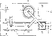
图1是表示本发明的一实施形态的切割装置概况的俯视图。Fig. 1 is a plan view showing an outline of a cutting device according to an embodiment of the present invention.
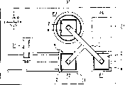
图2(A)是表示使旋转臂往复回转所用机构的图。Fig. 2(A) is a diagram showing a mechanism for reciprocating the rotating arm.
图2(B)是图2(A)所示穖构的动作说明图。FIG. 2(B) is an explanatory diagram of the operation of the structure shown in FIG. 2(A).
图3(A)是表示使吸附头升降及回转所用机构的图。Fig. 3(A) is a diagram showing a mechanism for raising and lowering and rotating the suction head.
图3(B)是表示图3(A)所示机构变形例的图。Fig. 3(B) is a diagram showing a modified example of the mechanism shown in Fig. 3(A).
图4(A)是工件供应器的说明图。FIG. 4(A) is an explanatory diagram of a workpiece feeder.
图4(B)是工件保管器的说明图。Fig. 4(B) is an explanatory diagram of the workpiece storage.
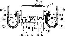
图5是表示将加工台向X方向移动所用的机构以及将切割头向Y、Z方向移动的机构的图。Fig. 5 is a diagram showing a mechanism for moving the processing table in the X direction and a mechanism for moving the cutting head in the Y and Z directions.
图6是图5的部分侧面图。FIG. 6 is a partial side view of FIG. 5 .
图7是工件洗净器的详细图。Fig. 7 is a detailed view of a workpiece washer.
图8是图1所示切割装置的动作说明图。Fig. 8 is an explanatory view showing the operation of the cutting device shown in Fig. 1 .
图9是图1所示切割装置的动作说明图。Fig. 9 is an explanatory view showing the operation of the cutting device shown in Fig. 1 .
图10是图1所示切割装置的动作说明图。Fig. 10 is an explanatory diagram of the operation of the cutting device shown in Fig. 1 .
图11是图1所示切割装置的动作说明图。Fig. 11 is an explanatory view showing the operation of the cutting device shown in Fig. 1 .
图12是图1所示切割装置的动作说明图。Fig. 12 is an explanatory view showing the operation of the cutting device shown in Fig. 1 .
图13是图1所示切割装置的动作说明图。Fig. 13 is an explanatory view showing the operation of the cutting device shown in Fig. 1 .
图14是图1所示切割装置的动作说明图。Fig. 14 is an explanatory view showing the operation of the cutting device shown in Fig. 1 .
图15是图1所示切割装置的动作说明图。Fig. 15 is an explanatory view showing the operation of the cutting device shown in Fig. 1 .
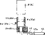
图16是表示防止冷却液溅入于加工台移动机构所用结结构的图。Fig. 16 is a diagram showing a junction structure for preventing coolant from splashing into the moving mechanism of the processing table.
图17是图16的A-A线剖面图。Fig. 17 is a sectional view taken along line A-A of Fig. 16 .
图18是表示图16所示结构的变形例的图。FIG. 18 is a diagram showing a modified example of the structure shown in FIG. 16 .
图19是表示图16所示结构的其它变形例的图。Fig. 19 is a diagram showing another modified example of the structure shown in Fig. 16 .
图20是表示图16所示结构的其它变形例的图。FIG. 20 is a diagram showing another modified example of the structure shown in FIG. 16 .
图21是表示图16所示结构的其它变形例的图。FIG. 21 is a diagram showing another modified example of the structure shown in FIG. 16 .
图22是表示图16所示结构的其它变形例的图。FIG. 22 is a diagram showing another modified example of the structure shown in FIG. 16 .
图23是表示图16所示结构的其它变形例的图。FIG. 23 is a diagram showing another modified example of the structure shown in FIG. 16 .
图24是表示用来防止冷却液的飞溅物溅入照相机所用结构的图。Fig. 24 is a diagram showing a structure for preventing splashes of cooling liquid from splashing into the camera.
图25是表示图24所示结构的变形例的图。Fig. 25 is a diagram showing a modified example of the structure shown in Fig. 24 .
图26是表示图24所示结构的其它变形例的图。Fig. 26 is a diagram showing another modified example of the structure shown in Fig. 24 .
图27是表示图24所示结构的其它变形例的图。Fig. 27 is a diagram showing another modified example of the structure shown in Fig. 24 .
图28是表示图24所示结构的其它变形例的图。Fig. 28 is a diagram showing another modified example of the structure shown in Fig. 24 .
图29是表示图24所示结构的其它变形例的图。Fig. 29 is a diagram showing another modified example of the structure shown in Fig. 24 .
图30是表示图24所示结构的其它变形例的图。Fig. 30 is a diagram showing another modified example of the structure shown in Fig. 24 .
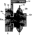
图31是表示用来防止由包含在冷却液的飞溅物的加工渣产生轴咬住所用结构的图。Fig. 31 is a diagram showing a structure for preventing shaft seizure by machining slag contained in coolant splash.
图32是表示图31所示结构的变形例的图。FIG. 32 is a diagram showing a modified example of the structure shown in FIG. 31 .
图33是表示用来防止由吸附头取出2片以上的工件所作结构的图。Fig. 33 is a view showing a structure for preventing two or more workpieces from being picked up by the suction head.
图34是表示图33所示结构的变形例的图。FIG. 34 is a diagram showing a modified example of the structure shown in FIG. 33 .
图35是表示由吸附头取出2片以上工件进行检测所用结构的图。Fig. 35 is a diagram showing a structure for taking out two or more workpieces by the suction head for inspection.
具体实施方式Detailed ways
现参照图1~图14就本发明的一实施形态说明如下。An embodiment of the present invention will be described below with reference to FIGS. 1 to 14 .
图1是表示切割装置概况的俯视图。图1中符号P1是供应切割前的工件W所用的第1位置,符号P2是在加工台上载放切割前的工件W所用的第2位置,符号P3是洗争切割后的工件W所用的第3位置,符号P4是保管洗净后的工件W所用的第4位置。又,图1中的符号1是运送工件的旋转臂,符号11是工件供应器,符号21是工件保管器,符号31是加工台,符号51是切割头,符号91是工件洗净器。Fig. 1 is a plan view showing an outline of a cutting device. In Fig. 1, the symbol P1 is the first position for supplying the workpiece W before cutting, the symbol P2 is the second position for placing the workpiece W before cutting on the processing table, and the symbol P3 is the first position for cleaning the workpiece W after cutting 3 positions, symbol P4 is the fourth position for storing the workpiece W after washing. Also, the symbol 1 in FIG. 1 is a rotating arm for transporting workpieces, the
即,在图中所示装置中,作为上述工作W的矩形陶瓷层压板为层压电容器或层压电感器或层压复合零件等的层压型电子零件的陶瓷层压板。该陶瓷层压板是在具有粘着层的树脂薄膜上层压多个陶瓷薄膜加以压紧,通过切割分开为各个芯片后,将所分开的芯片从树脂薄膜取出加以烘烤,并通过在烘烤后的芯片上形成外部电极就可变成所需的层压型电子零件。That is, in the device shown in the figure, the rectangular ceramic laminate as the above-mentioned work W is a ceramic laminate of laminated electronic components such as laminated capacitors, laminated inductors, or laminated composite parts. The ceramic laminate is laminated with a plurality of ceramic films on a resin film with an adhesive layer to be pressed, and after being cut and separated into individual chips, the separated chips are taken out from the resin film and baked, and passed through after baking. By forming external electrodes on the chip, it becomes desired laminated electronic parts.
第1位置P1~P4的位置P4是在同一圆周上向顺时针方向以90度间隔加以配置,在此圆周的中心装设有旋转臂1的轴1b。旋转臂1是将长度相等的3个臂部1a以轴1b作为中心沿上述圆周成为具有90度间隔的T字状。在各臂部1a前端部分别设有工件固持用的吸附头2。The position P4 of the first positions P1 to P4 is arranged at intervals of 90 degrees in the clockwise direction on the same circumference, and the
如图2(A)所示,在旋转臂1的轴1b上连接有连杆1c的一端,在连杆1c另一端连接有旋转臂驱动用的压缸3的杆3a。旋转臂1由压缸3的杆伸缩可回转90度,并由于该回转而往复回转于如图2(A)所示与图2(B)所示位置之间。在图2(A)所示位置有3个吸附头2分别对峙于第1位置P1~第3位置P3,在图2(B)所示位置有3个吸附头2分别对峙于第2位置P2~第4位置P4。当然,也可以在旋转臂1的轴1b连接马达,藉此马达的动作而使旋转臂1往复回转。As shown in FIG. 2(A), one end of a
吸附头2的下面形状呈矩形状,其下面具有由软质树脂或合成橡胶等所构成的弹性垫2a。虽然省略了图标,但在此弹性垫2a中形成有十字形沟或平行沟,在沟内面设有吸引孔。又,此吸引孔连接于具有真空泵及阀等的空气回路。也就是说,对于吸引孔作用负压以接触子弹性垫2a的状态加以吸附保持,并通过解除负压来解除其保持。另外,3个吸附头2也可以为具有上述以外的结构。另外,也可采用分别将切割前的工件W从工件供应器11在运送至加工台31所用的吸附头2、将切割后的工件W从加工台31运送至工件洗净器91所用的吸附头2、将洗净后的工件W从工件洗净器91运送至工件保管器21所用的吸附头2配合被运送的工件W表面形状的结构。The lower surface of the
又,如图3(A)所示,各吸附头2是在上面中央具有升降轴2b,设于各臂部1a前端部的衬套1d将升降轴2b插通成可上下移动。在各臂部1a前端部,使用托架4将马达5配置成向下,上述升降轴2b的上端部插入于形成为中空的马达轴5a内。又,在托架4向下配置有压缸6,此压缸6的杆6a在设于上述升降轴2b的轴承2c中经构件7连接。由二吸附头2的升降轴2b对于马达轴5a只能上下移动,所以吸附头2是通过马达5的动作而回转,并通过压缸6的动作而升降。Also, as shown in FIG. 3(A), each
使吸附头2产生回转与升降动作的机构可采用图3(A)所示以外的机构,图3B表示其一例,吸附头2的升降轴2b上连接有马达5的轴5a,竖设于臂部1a的压缸6的杆6a经由构件7连接于马达5。The mechanism that makes
如图4(A)所示,在上述第1位置P1处配置有工件供应器11。该工件供应器11具有;切割前的工件W多个重叠的升降板12,连接于升降板12的导板13,支承2个支导杆14与球螺旋15的支承板16,在滚珠丝杆15的一端具有连接其轴17a的马达17。在导板13上设有插通导杆14的2个衬套13a,与螺合于滚珠丝杆15的螺母13b。该工件供应器11是由马达17转动滚珠丝杆15并通过将升降板12间歇性地上升而将最高位的工件W的供应高度调整为一定,可从取出口18取出工件。虽然省略了图标,但在升降板12周围配置有使重叠于升降板12上的工件W上升时或待机状态下防止产生崩落或位置偏移的多个导杆。As shown in FIG. 4(A), the
在上述第4位置P4处配置有如图4(B)的工件保管器21。此工件保管器21具有与上述工件供应器11相同的结构,具有;重叠洗净后的工件W的升降板22,连接于升降板22的导板23,支承2支导杆24的滚珠丝杆25的支承板26,与在滚珠丝杆25一端连接其轴27a的马达27。在导板23上设有插通有导杆24的2个衬套23a,与螺合于滚珠丝杆25的螺母23b。该工件保管器21是将洗净后的工件W通过保管口28并由升降板22承接,第2个以后的工件W可在其上依次重叠加以保管。又,使升降板22藉由马达27转动滚珠丝杆25而间歇性地下降,可将升降板22的承接高度调整为一定。虽然省略了图标,但在升降板22周围配置有防止重叠于升降板22上的工件W在下降时或待机状态下发生崩落或偏移所需的多个导杆。The
在上述第2位置P2处配置有加工台31。如图5及图6所示,具有;可向θ方向回转的矩形工件支承板32,对工件支承板32回转自如地加以支承的滑动加工台33,将工件支承板32向θ方向回转驱动的马达(省略图标)。虽然省略了图标,但在工件支承板32设有多个吸引孔,这些吸引孔连接于具有真空泵及阀等的空气回路。亦即,工件W是藉对于吸引孔作用负压成为接触于工件支承板32状态而吸附固持,并通过解除负压作用来解除其固持。The processing table 31 is arrange|positioned at the said 2nd position P2. As shown in Fig. 5 and Fig. 6, there are: a rectangular
该加工台31可为从第2位置P2向离开X方向(参照图1)的切割区域移动,以及从此切割区域向第2位置P2移动。将加工台31向X方向(参照图1)移动的机构如图5及图6所示,具有;加工台板41,支承于加工台板41上的X方向的一对导板42,在加工台板41上回转自如地支承的X方向的滚珠丝杆43,在滚珠丝杆43一端连接其轴44a的马达44,卡合于可移动于一对导板42地设于上述加工台31下面的二对滑动导件45,设于上述加工台31下面而螺合滚珠丝杆43的螺母46。亦即,上述加工台31是通过由马达44转动滚珠丝杆43而沿着导板42向X方向移动。The processing table 31 can move from the second position P2 to the cutting area away from the X direction (see FIG. 1 ), and from the cutting area to the second position P2. The mechanism that processing table 31 is moved to X direction (referring to Fig. 1) has as shown in Figure 5 and Figure 6; A
在上述切割区域中配置有切割头51。此切割头51如图5及图6所示,具有;圆筒形的主轴马达52,与装卸自如地固定于主轴马达52的轴52a的金刚石刀片等的刀片53,使刀片53下部露出覆盖其外侧的刀片盖板54,从刀片盖板54内面向刀片53供应水等冷却液的冷却液喷射口(省略图标)。主轴马达52的方向与上述加工台31的工件支承板32表面平行,并与加工台3 1的移动方向成直交,刀片53的方向与加工台31的移动方向平行。A cutting
此切割头51可在X方向直交的Y方向(参照图1)和上下方向的Z方向(参照图1)移动。使切割头51向Y方向与Z方向移动的机构如图5及图6所示,具有;支柱61,与,支承于支柱61侧面的Y方向的一对导轨62,在支承61侧面支承成回转自如的滚珠丝杆63,在滚珠丝杆63一端连接其轴的马达64,对于一对导轨62卡合成可移动的二对滑动导件65,螺合于滚珠丝杆63的螺母66,连接有滑动导件65及螺母66的第1滑动板67,支承于第1滑动板67侧面的Z方向的一对导轨68,回转自如地支承于第1滑动板67侧面的滚珠丝杆69,在滚珠丝杆69一端连接其轴的马达70,卡合成可移动于一对导轨68的二对滑动导件72,螺合于滚珠丝杆69的螺母72,连接滑动导件71及螺母72的第二滑动板73,在第二滑动板73下部连接上述切割头51的主轴马达52前部及后部所用的2个连接构件74。亦即,上述切割头51是由马达64回转滚珠丝杆63将第一滑动板67沿着导轨62移动而向Y方向移动。又,由马达70回转滚珠丝杆69将第二滑动板73沿着导轨68移动而向Z方向移动。The cutting
又,在上述第一滑动板67的加工台侧沿Y方向配置有内藏CCD等2维摄像组件的2个照相机81、82。此2个照相机81、82是用于对摄像加工台31上的工件W进行摄像并对工件W进行位置检测,在图示例子中,作为靠近第一滑动板67的照相机81采用高倍率,作为另一方的照相机82采用低倍率。In addition, two
如图7所示,在上述第3位置P3中,配置有工件洗净器91。此工件洗净器91具有;上端开口的固定筒92,配置于固定筒92内的转盘93,回转转盘93所用的马达94,向马达94供应水等洗净液所用的洗净喷射口95,向转盘93供应空气等干燥用气体所用的气体喷射口96,防止洗净液浸入于马达94侧所用的防水盖97。虽然省略了图标,但是在转盘93设有多个吸引孔,这些吸引孔连接于备有真空泵及阀等的空气回路。亦即,工件W是藉对于吸引孔作用负压成为接触于工件支承板32的状态而被吸附保持,并通过解除负压作用解除其保持。As shown in FIG. 7 , a
现就上述的切割装置的动作说明如下。The action of the above-mentioned cutting device is now described as follows.
开始动作前,旋转臂1位于第1图所示位置,此旋转臂1的3个吸附头2分别对峙于第1位置P1~第3位置P3。Before starting the operation, the rotary arm 1 is located at the position shown in FIG. 1 , and the three
动作开始后,首先,以第1状态下降旋转臂1的图中右下的吸附头2,藉此吸附头2吸附保持工件供应器11中的第1片工件W,在工件保持后将此吸附头2上升复原。After the operation starts, firstly, the
接着,如图8所示,使旋转臂1向图中顺时针方向回转90度,在此,使保持第1片的工件W吸附头2下降并将此工件W载放于加工台31上。载放后解除工件保持并将此吸附头2上升复原。载放于加工台31上的工件W被吸附保持于工件支承板32上。Next, as shown in FIG. 8 , the rotating arm 1 is rotated 90 degrees clockwise in the drawing, and the
接着,如图9所示,将旋转臂1向图中向逆时针方向回转90度。大致与此同时,将载放工件W的加工台31从第2位置P3移动至切割区域。Next, as shown in FIG. 9 , the rotating arm 1 is turned 90 degrees counterclockwise in the figure. At substantially the same time, the processing table 31 on which the workpiece W is placed is moved from the second position P3 to the cutting area.
当加工台31移动到切割区域时,藉低倍率的照相机82(参照图6)对加工台31上的工件W进行摄像,依据此摄像数据缩小检测区域。并且,藉由高倍率的照相机81(参照图6)对工件W的检测区域进行摄像,依据此摄像就可检出工件W的正确位置。检出此位置后,就依据检测信息对加工台31上的工件W实施切割。When the processing table 31 moves to the cutting area, the workpiece W on the processing table 31 is photographed by the low-magnification camera 82 (refer to FIG. 6 ), and the detection area is narrowed according to the imaging data. In addition, the detection area of the workpiece W is imaged by a high-magnification camera 81 (see FIG. 6 ), and the correct position of the workpiece W can be detected based on the imaging. After the position is detected, the workpiece W on the processing table 31 is cut according to the detected information.
具体地说,首先,使可沿X方向移动的加工台31与可自Y、Z方向移动的切割头51作适当移动,并决定对于工件W的刀片53的起始位置。并一边转动切割头51的刀片53一边将加工台31沿X方向以一定速度移动,对于工件W实施第一线的切断。结束第一线的切断之后,使切割头51沿Z方向上侧移动一定距离,并将刀片53从工件W离开,并使加工台31与上述相反方向移动,同时使切割头51沿Y方向移动一定距离并进行换行。并使切割头51沿Z方向移动一定距离以对准高度位置,与上述同样地使加工台31沿X方向以一定速度移动,对于工件W实施第二线的切断。此后反复与上述同样的动作,并反复相同方向的切断所需线数。接着,使加工台31沿θ方向转动90度以改变工件W的方向之后,与上述同样反复与先前所形成的线成直交方向的切断所需线数的切断。当然,也可在结束一条线的切断之后,在使加工台31沿相反方向移动时进行下一条线的切断。藉此,加工台31上的工件W就被切断成格子状而切断成各个芯片。如上所述,在工件W下面经由粘着层张贴树脂薄膜,故被切断的芯片将维持张贴于树脂薄膜的状态。另外,在上述切割时,从设于刀片盖板54的冷却液喷射口向刀片53供应冷却液,藉此去除由刀片53的冷却与切断所产生的加工渣(陶瓷微细粉等)。Specifically, first, the processing table 31 movable in the X direction and the cutting
切割结束后,如图10所示,将加工台31返回第2位置P2。而后,降下旋转臂1的图中左下方的吸附头2,吸附保持由此吸附头2切割完毕时加工台31上的工件W,并在固持工件后将此吸附头2复原为上升位置。并且,下降旋转臂1的图中右下方的吸附头2,藉此吸附头2吸附固持于工件供应器11的第2片工件W,固持工件W后使该吸附头2上升复原。After the cutting is completed, as shown in FIG. 10 , the processing table 31 is returned to the second position P2. Then, lower the
接着,如图11所示,将旋转臂1沿图中顺时针方向回转90度,在此,使保持已切割完的工件W的吸附头2下降并将此工件W载放于工件洗净器91的转盘92上。载放后解除工件固持并使此吸附头2上升复原,将载放工件W吸附固持于转盘92上。并且,降低将保持第二片的工件W的吸附头2并将此工件W载放于加工台51上。载放后解除工件品持之后使此吸附头2上升复原,将载放工件W吸附固持于工件支承板32上。Next, as shown in FIG. 11 , the rotating arm 1 is rotated 90 degrees clockwise in the drawing, and here, the
接着,如图12所示,不仅将旋转臂1沿图中逆时针方向回转90度,并且,将载放工件W的加工台31从第2位置P2移动至切割区域。当加工台31移动至切割区域后,实施与上述同样的位置检测与切割,同时利用切割的时间,在工件洗净器91中对于转盘92上的已切割的工件W实施洗净。Next, as shown in FIG. 12 , not only the rotary arm 1 is rotated 90 degrees counterclockwise in the drawing, but also the processing table 31 on which the workpiece W is placed is moved from the second position P2 to the cutting area. After the processing table 31 moves to the cutting area, the same position detection and cutting as above are performed, and at the same time, the cut workpiece W on the turntable 92 is cleaned in the
具体地说,为从洗净喷射口95一边向转盘92上的工件W供应洗净液一边使转盘92转动一定数的洗净步骤,朝向转盘92上的工件W从气体喷射口96一边供应干燥用气体一边使转盘92转动一定转数的干燥步骤,且每隔一定时间反复一次以上,并对已切割的工件W实施洗净。洗净后的洗净液从设于固定筒92或防水盖97的排水口(省略图标)排出到外部。Specifically, for the cleaning step of rotating the turntable 92 by a certain number of times while supplying cleaning liquid from the cleaning injection port 95 to the workpiece W on the turntable 92, the dry air is supplied from the gas injection port 96 toward the workpiece W on the turntable 92. The drying step of rotating the turntable 92 by a certain number of revolutions with gas is repeated once or more at regular intervals, and the cut workpiece W is washed. The washing liquid after washing is discharged to the outside from a drain port (not shown) provided in the fixed cylinder 92 or the waterproof cover 97 .
切割与洗净结束之后,如图13所示,将加工台31返回第2位置P2。并使旋转臂1的图中左上方的吸附头2下降,藉此吸附头2将工件洗净器91的转盘92上的已洗净完的工件W吸附固持,固持工件后使此吸附头2上升复原。另外,使旋转臂1的中左下方的吸附头2下降,藉此吸附头2吸附固持加工台31上的已切割工件W,固持工件后使此吸附头2上升复原。并使旋转臂1的图中右下方吸附头2下降,藉此吸附头2吸附固持于工件供应器11的第三片工件W,固持工件后将此吸附头2上升复原。After cutting and cleaning are completed, as shown in FIG. 13 , the processing table 31 is returned to the second position P2. And the
接着,如图14所示,将旋转臂1沿图中顺时针方向回转90度,于此,使已洗净的工件W的吸附头2下降固持并将此工件W载放在工件保管器21的升降板22上。载放后解除工件固持后使此吸附头2上升复原。另外,使已切割的工件W的吸附头2下降固持,将此工件W载放于工件洗净器91的转盘92。载放后解除固持工件后使此吸附头2上升复原,将载放工件W吸附固持于转盘92。并使第三片工件W下降固持并将此工件W载放于加工台31。载放后解除固持工件后使此吸附头2上升复原,使载放工件W吸附固持工件支承板32。Next, as shown in FIG. 14 , the rotating arm 1 is rotated 90 degrees clockwise in the figure, and here, the
此后反复图12~图14所说明步骤,连续进行对于工件W的切割与洗净保管。Thereafter, the steps described in FIGS. 12 to 14 are repeated, and the workpiece W is cut, cleaned and stored continuously.
这样,若依据上述切割装置,将供应切割前的工件W的第1位置P1、在加工台31上载放切割前次工件W的第2位置,洗净切割后的工件W的第3位置、以及保管洗净后的工件的第4位置P4在同一圆周上以90度间隔沿顺时针方向配置,并且,在上述圆周中心具有旋转臂1b的旋转臂1沿着上述圆周以90度间隔配置有3个吸附头2,所以,通过使旋转臂1以90度角度往复回转,就可正确地进行从第1位置P1向第2位置P2的工件运送、从第2位置P2向第3位置P3的工件运送、以及从第3位置P3向第4位置P4的工件运送。In this way, according to the above-mentioned cutting device, the first position P1 for supplying the workpiece W before cutting, the second position for placing the workpiece W before cutting on the processing table 31, the third position for cleaning the workpiece W after cutting, and The fourth position P4 for storing the cleaned workpieces is arranged clockwise at intervals of 90 degrees on the same circumference, and the rotation arm 1 having the
也就是说,旋转臂1因只在第1位置P1~第3位置P3分别对峙3个吸附头2的位置,与在第2位置P2~第4位置P4分别对峙3个吸附头2的位置之间反复回转,所以,不需要将旋转臂1在大于90度角度范围回转,通过尽量小的角度范围的反复回转即可高效稳定地进行所需工件的运送。That is to say, because the rotating arm 1 only faces the positions of the three
又,上述的切割装置在其机能方面因不进行从第4位置到第1位置的工件运送,所以,在旋转臂1向沿着上述圆周以90度间隔装设3个吸附头2时,为可同时运送最多的工件W的状态,亦即,即使从第1位置P1到第2位置P2的工件运送、从第2位置P2到第3位置P3的工件运送、以及从第3位置P3到第4位置P4的工件运送同时进行的状态,也可良好地进行此时的工件运送。换言之,不需要装设旋转臂1不需要的吸附头2。并且,作为旋转臂1可采用T字形,故可简化旋转臂本身结构,减轻成本或维修方面的负担。Also, the above-mentioned cutting device does not carry out workpiece transportation from the 4th position to the 1st position in terms of its function, so when the rotating arm 1 is installed with 90 degree intervals along the above-mentioned circumference, the three
并且,在上述的切割装置中,在旋转臂1上装设有将三个吸附头2个别升降及回转所需的致动器,所以,第1位置P1与第2位置P2间、第2位置P2与第3位置P3间,或从第3位置到第4位置间即使具有高低差或障碍物时通过适当升降吸附头2即可毫无障碍地、良好地进行所需的工件运送。又,被运送的工件W方向即使包含运送途中发生变化时,通过适当转动吸附头2即可简单地矫正运送工件W的方向。In addition, in the cutting device described above, the rotating arm 1 is provided with the actuators required to individually lift and rotate the three
因此,如图15所示,在第2位置P3与第3位置P4间,运送途中的工件W及吸附头2可能冲突的障碍物OB例如存在有将切割头51与Y、Z方向移动所用的致动器一部分时,通过由吸附头2吸附固持加工台31上的已切割的工件W后,将此吸附头2沿顺时针方向或逆时针方向回转45度后,将旋转臂1沿图中顺时针方向回转90度即可。若这样做时,当工件W及吸附头2从第2位置P3移动至第4位置P4时就可防范工件W及吸附头2与障碍物OB冲突。但是,若在第2位置P2沿顺时针方向或逆时针方向回转45度时,沿第3位置P3的工件W及吸附头2的方向由于仍保持回转45度的回转位置,所以将已切割的工件W载放于工件洗净器91的转盘92的前阶段将吸附头2沿顺时针方向或逆时针方向回转45度,或,洗净后将转盘92回转±45度时,就可将工件W及吸附头2方向恢复为原本状态。Therefore, as shown in Figure 15, between the 2nd position P3 and the 3rd position P4, the obstacle OB that the workpiece W and the
另外,在上述的切割装置中,作为工件W表示了陶瓷层压板,但是对于陶瓷层压板以外的工件W,例如,半导体晶圆或集成电路晶圆切割为各个芯片时也可使用上述的装置,可获得与上述同样的作用效果。In addition, in the above-mentioned dicing device, a ceramic laminate was shown as the workpiece W, but the above-mentioned device can also be used for a workpiece W other than a ceramic laminate, for example, when a semiconductor wafer or an integrated circuit wafer is diced into individual chips. The same effect as above can be obtained.
又,在上述切割装置中,作为旋转臂1表示了T字形,但是,只要是将3个吸附头在同一圆周上具有90度间隔时,旋转臂并不一定要成为T字形。In addition, in the above-mentioned cutting device, the T-shape was shown as the rotating arm 1 , but the rotating arm does not have to be T-shaped as long as the three suction heads are spaced at 90 degrees on the same circumference.
并且,在上述切割装置中,是在成T字形的旋转臂1的各臂部1a前端部装设了吸附头2,但如将各臂部1a作为至少二段可伸缩的结构、或将各臂部1a在铰链部作为可折弯的结构时,通过使臂部1a适当伸缩或折弯使吸附头2回避,即可更简单地进行各位置P1~P4的维修。And, in above-mentioned cutting device, be to install
图16及图17表示防止在切割时向刀片53供应后的冷却液进入使加工台31沿X方向移动所用机构的有用结构。16 and 17 show useful structures for preventing the coolant supplied to the
图中的符号101是在加工台31的滑动加工台33周围安装成水密的横剖面呈コ字形的防水盖,符号102是在防水盖101的X方向两端将其一端水密地连接的横剖面呈コ字形的一对伸缩盖。此伸缩盖102是在氯丁橡胶或硅等的合成橡胶或芯布上施加树脂涂层作为其材料形成为伸缩囊状,当加工台31沿X方向移动时与其配合会适当伸缩。又,符号103是与一对伸缩盖102另一端水密地连接的一对支承板,符号104是将两端水密地连接于支承板103的横剖面U字形的排水构件,一对支承板103安装于加工台板41。又,一对排水构件104在加工台31两端配置成互相平行,横剖面コ字形的防水盖101的垂直部分进入于防水盖101的内侧。The
符号105是分别配置于一对排水构件104内侧的螺旋状刷子。各刷子105的中心轴由一对支承板103回转自如地支持,将其下侧部分接触于排水构件104的内底。在二支螺旋状刷子105的轴一端分别安装有带轮106,在此带轮106上卷绕有皮带107。又,在另一方的螺旋状刷子105的轴一端安装有上述另外的带轮106,此带轮106与安装于马达108轴的带轮106上卷绕有皮带107。即,二支螺旋状刷子105由马达108的动作将其轴作为中心沿同一方向回转。因此,一对排水构件104为装设带轮侧较另一方侧更高,或相反地倾斜,在低位侧的底或端处设有省略图标的排水口。又,二支螺旋状刷子105并不妨碍倾斜的排水构件104的自然排水,并向可促进排水的方向回转。
如上所述,对于加工台31上的工件W实施切割时,从设于刀片盖板54的冷却液喷射口向刀片53供应冷却液,藉以去除由刀片53的冷却与切断所发生的加工渣。包含有加工渣的冷却液如图17以箭头所示流动并从防水盖101及伸缩盖102流入排水构件104内。此冷却液沿排水构件104的倾斜流动而从排水口排水。又,此时是由马达108带动二个螺旋状刷子105回转,使留在排水构件104内底的加工渣向排水口方向移动。As described above, when the workpiece W on the machining table 31 is cut, the coolant is supplied to the
也就是说,若没有如上述螺旋状刷子105时,包含在冷却液的加工渣将成为停留于排水构件104内底的状态,但是若使用如上述的螺旋状刷子105使其回转时,就使停留于排水构件104内底的加工渣可向排水口方向移动加以排出,藉此由停留于内底的加工渣可防范从排水构件104的冷却液溢流。That is, if there is no
又,防水盖101与伸缩盖102均为横剖面呈コ字形,并且,防水盖101的垂直部分进入于防水盖101内侧,所以从加工台31流入防水盖101内的冷却液不至于进入于包含导板42或滚珠丝杆43等的加工台移动机构。Again, both the
需进行更可靠的防水时,如图18所示,将与上述防水盖101具有同样形状的第2防水盖110在滑动加工台33周围安装成水密,并且,在此第2防水盖110的X方向两端将与上述伸缩盖102具有同样形状的一对第2伸缩盖(省略图标)一端水密地连接并将另一端水密地连接于支承板103即可。这样,就可双重防止冷却液进入加工台移动机构。When more reliable waterproofing is required, as shown in FIG. 18 , a second
另外,使停留于排水构件104内底的加工渣沿排水口方向移动即使不使用上述的螺旋状刷子105也可进行。例如,如图19所示,将其下侧部分接触于排水构件104内底,较佳为将可挠性刮取板111经由杆111a安装于防水盖101时,当加工台31沿X方向移动时同时移动刮取板111,使停留于排水构件104内底的加工渣可向排水口方向移动。此时,使由刮取板111的加工渣的移动不能限制成单向,所以配合刮取板111的移动范围将多个排水口装设于排水构件104的内底即可。当然,如图20所示,将与上述同样的刮取板112安装于压缸113的杆113a使其可升降时,藉使刮取板112向下状态移动,就可将由刮取板112的加工渣移动限制为朝单向。又,如图21所示,将与上述同样的刮取板114的上端经由杆114a回转自如地安装于防水盖101,将此刮取板114的回转方向由挡止销SP加以限制时,就可将刮取板114的加工渣移动限制成单向。In addition, it is possible to move the slag remaining on the inner bottom of the
又,如图22所示,在安装于防水盖101的支承构件115中安装具有防水机构的马达116,在此马达116中安装圆筒状刷子117并使其下侧部分接触于排水构件104内底时,当加工台31沿X方向移动时藉同时将刷子117沿既定方向回转就可使停留于排水构件104内底的加工渣沿排水口方向移动。Also, as shown in FIG. 22 , a motor 116 with a waterproof mechanism is installed in the support member 115 installed on the
并且,如图23所示,在安装于防水盖101的支承构件118上回转自如地设有杆119,此杆119上装设滚轮120并将此滚轮120接触于设在排水构件104内面或设在内面的轨道121,并且,在杆119下端安装球状刷子122并将其下侧部分接触于排水构件104内底时,当加工台31沿X方向移动时藉同时回转的滚轮120就可使刷子117回转,藉此就可使停留于排水构件104内底的加工渣向排水口方向移动。此时,如作为上述滚轮120采用小齿轮、而作为轨道121采用齿条,可使随着加工台移动的刷子117的回转更正确地进行。And, as shown in FIG. 23 , a
图24表示用来防止切割时向刀片53供应的冷却液或所供应后的冷却液由于刀片53的飞溅而沾附于照相机81、82的物镜而产生摄像不良的有用结构。FIG. 24 shows a useful structure for preventing the coolant supplied to the
图中的符号81、82为照相机,符号81a、82a是物镜,符号81b、82b是安装于照相机81、82下部的筒状,81c、82c是安装于透镜遮光罩81b、82b下部的照明器。照明器81c、82c是透过光纤等所导入的光线向图中粗线箭头方向传播而从其下面成环状照射,在摄像时照明工件W。在81b、82b周围设有吸气口81b1、82b1,在此吸气口81b1、82b1连接有具有空气压缩机及阀等的空气回路。
如上所述,对于加工台31上的工件W需加以切割时,从设在刀片益板54的冷却液喷射口向刀片53供应冷却液,藉此去除由于刀片53的冷却与切割所产生的加工渣。向刀片53所供应的冷却液或所供应后的冷却液因刀片53的回转虽然会飞溅于周围,但是此时从吸气口81b1、82b1对于透镜遮光罩81b、82b内供应空气,并将此空气从透镜遮光罩81b、82b的下面开口喷出到外部。As mentioned above, when the workpiece W on the processing table 31 needs to be cut, the cooling liquid is supplied to the
也就是说,在向刀片53供应的冷却液或供应后的冷却液因刀片53的回转即使会飞溅于周围的情形下,可由上述空气喷出可靠地防止此飞溅物进入于透镜遮光罩81b、82b内或飞溅物沾附于物镜81a、82a,故可良好地实施摄像。That is, even if the coolant supplied to the
图25是在图24所示结构中装设开闭挡门,图中的符号125是压缸,符号126是设在压缸125的杆125a的挡门。压缸125固定于支承照相机81、82的构件上。当对于加工台31上的工件W实施切割时,藉由挡门126堵住透镜遮光罩81b、82b的下面开口时就可更加可靠防止冷却液的飞溅物进入透镜遮光罩81b、82b内。Fig. 25 is to install opening and closing door in the structure shown in Fig. 24, and
另外,由于冷却液的飞溅物沾附而引起摄像不良的问题即使用上述以外的结构也能防止。如图26所示,在透镜遮光罩81b、82b的下面开口安装亲水性的透明滤光器131,在将液体的膜较佳地为均匀沾附时,与水滴分散吸附时相比可抑制对于摄像的影响。In addition, it is also possible to prevent the problem of imaging failure due to the adhesion of splashes of the cooling liquid even with structures other than the above. As shown in Figure 26, a hydrophilic transparent filter 131 is installed in the lower openings of the lens shades 81b, 82b, and when the film of the liquid is preferably evenly attached, it can suppress the water drop compared with when the water drop is dispersed and adsorbed. impact on photography.
又,如图27所示,在透镜遮光罩81b、82b的下面开口安装拨水性的透明滤光器132,并在透镜遮光罩81b、82b上设吸气口81b2、82b2与向遮光罩下面的通气路81b3、82b3,在通气路81b3、82b3下端装设向滤光器131下面的喷嘴133时,从吸气口81b2、82b2经由通气路81b3、82b3从喷嘴133向滤光器131喷出空气,将沾附于滤光器131的冷却液喷出而将此飞溅物去除,即可消除摄像不良的问题。由于作为滤光器131采用拨水性,所以由上述喷出空气去除沾附物也变成容易。Again, as shown in Figure 27, the water-repellent
并且,如图28所示,在透镜遮光罩81b、82b的下面开口内面在不妨碍摄像视野的范围设置吸水性构件134例如吸水性树脂层时,将冷却液飞溅物由此吸水性构件134积极地吸收以防止飞溅物进入透镜方向,即可消除摄像不良的问题。And, as shown in FIG. 28, when a water-absorbing member 134, such as a water-absorbing resin layer, is provided on the inner surface of the lower opening of the lens shades 81b, 82b in a range that does not hinder the imaging field of view, the water-absorbing member 134 actively prevents the coolant from splashing. Absorption to prevent splashes from entering the direction of the lens can eliminate the problem of poor imaging.
并且如图29所示,在透镜遮光罩81b、82b下面两侧配置送出透明胶卷135所用的带轮136与卷绕所用的带轮137,若卷绕带轮137由马达138加以回转时,每当覆盖透镜遮光罩81b、82b下面开口的透明胶卷135由于冷却液的飞溅物污染时,通过卷取一定长度的此透明胶卷135,即可消除摄像不良的问题。此时,若将去除被卷取的透明胶卷135的污染吸水垫等设于卷取侧时,也可再利用已用完的透明胶卷135,若在送出带轮136侧也装设马达,也可使透明胶卷135逆向移动并反复使用。And as shown in Figure 29, the
如图30所示,将多个过滤器139a在同一圆周上具有以等角度间隔的过滤板139的中心安装于马达140的轴140a时,每当覆盖透镜遮光罩81b、82b下面开口的过滤器139a由于冷却液的飞溅污染而使滤光板139回转一定角度并将此滤光器139a转换为另外滤光器139a,也可消除摄像不良的问题。As shown in FIG. 30, when a plurality of filters 139a are mounted on the shaft 140a of the motor 140 at the center of the filter plates 139 having equiangular intervals on the same circumference, each time the filters that cover the lower openings of the
并且,在切割头51与照相机81、82之间即使配置冷却液的飞溅物遮住从切割头51向照相机81、82流动所用的遮蔽物(省略图标),也可防止飞溅物沾附于照相机81、82。此遮蔽物也可以安装于第一滑动板67与第二滑动板73的至少一方而加以一起移,或也可以固定配置于装置本体。And, even if the splash of coolant is arranged between the cutting
图31表示防止切割时向刀片53所供应后的冷却液中所含有的加工渣进入分割头51的心轴马达52侧而转动接触于轴52a而产生所谓咬住的有益的结构。FIG. 31 shows an advantageous structure that prevents machining slag contained in the cooling liquid supplied to the
图中的符号51为切割头,符号52是主轴马达,符号52a是主轴马达52的轴,符号52b是刀片押压构件,符号52c是将刀片押压构件52b固定于轴52a所用的锁紧件,符号53是圆盘状的刀片,符号54是刀片盖板54。轴52a采用在主轴马达52的机壳内转动自如地配置的止推轴承与径向轴承。在主轴马达52的机壳与轴52a之间具有约1mm的间隙,又,在轴52a与刀片盖板54之间也具有同样的间隙。亦即,在主轴马达52的机壳及刀片盖板54与轴52a之间形成有如图所示的弯曲间隙G。又,主轴马达52的机壳设有吸气口(省略图标),在此吸气口连接于具有空气压缩机及阀等的空气回路。亦即,从吸气口向机壳内供应空气的状态下,上述间隙G将具有空气轴承的作用。The
切割时,当从吸气口向机壳内供应空气时,此空气流经上述间隙G从轴52a周围喷出于刀片侧。切割时向刀片53供应后的冷却液的飞溅物原为进入轴52a与刀片盖板54之间,但是由于上述的喷出空气,可排除此飞溅物,又,在防止飞溅物中所含的加工渣进入于上述间隙G的同时防止上述轴的咬住。When cutting, when air is supplied into the casing from the suction port, the air flows through the gap G and is ejected from around the
另外,由于间隙G开启端的空气压力降低引起在此开启端附近部分沾附加工渣而堆积的情形时,如图32所示,也可在该部分设间隙G的旁通通路54a,积极地防止在该部分沾附加工渣。又,将容易沾附加工渣的部分由多孔质构件构成,使其即使从该整个构件流出空气也可得到同样的效果。In addition, when the air pressure at the opening end of the gap G is reduced and the slag is attached to and accumulated near the opening end, as shown in FIG. Apply additional slag to this part. In addition, the same effect can be obtained even if the part where the slag is easily attached is made of a porous member so that air flows out from the entire member.
图33表示在从重叠于工件供应器11的升降板12上的工件W由吸附头2取出最上位的工件W时,以防止固工件互相的密贴而取出2片以上工件W的有用的结构。33 shows a useful structure for taking out two or more workpieces W by preventing the solid workpieces from sticking to each other when the uppermost workpiece W is taken out by the
图中的符号12是工件供应器11的升降板,符号18是取出口,符号W是堆积于升降板12上的工件W。符号15是安装于升降板12上的发生微振动用的振动源。由吸附头2取出最上位的工件W时,当吸附头2接触于工件W时即激活振动源并给与全部工件W微振动。即使最上位的工件W与其下侧的工件W密贴时,也由于上述微振动可分开两者,藉此可防止由吸附头2取出2片以上的工件W。In the figure,
另外,防止由吸附头2取出2片以上的工件W也可采用上述以外的方法。如图34所示,在吸附头2外周缘配置多个压缸152,使其杆152a可从吸附头2下面(垫2a的下面)突出,当吸附头2取出最上位的工件W时预先使杆152a从吸附头2下面稍为突出,在此状态下将吸附头2接触于最上位工件W进行吸附时,由吸引力使最上位的工件W挠曲成如图中虚线所示,即可与下侧的工件W分开。此后,拉入杆152a时,即可解除上述的挠曲并以适当状态由吸附头2吸附固持工件W。即使这样,也可防止由吸附头2取出2片以上的工件W。In addition, methods other than those described above may be employed to prevent two or more workpieces W from being taken out by the
图35表示用来检测被取出2片以上的工件W的结构,在此,将由发光器153与受光器154所构成的光线开关设于取出口,依据此光线开关的检测讯号来判断工件的的取出情形的良否。即,若将光线开关的检测光线设定成只与最上位的工件W碰触,当取出2片以上的工件W时,其后即使将升降板12上升工件1片分量,因光线开关不会变成关闭,故可利用此讯号判断2片以上的工件W被取出的情形。当判断2片以上的工件W被取出时若使装置的动作暂停,就可利用此停止期间对工件取出不良的情形进行修正。Fig. 35 shows a structure for detecting two or more workpieces W that have been taken out. Here, a light switch composed of a light emitter 153 and a light receiver 154 is installed at the take-out port, and the quality of the workpiece is judged based on the detection signal of the light switch. Take out whether the situation is good or not. That is, if the detection light of the optical switch is set to touch only the uppermost workpiece W, when two or more workpieces W are taken out, even if the lifting
本说明书所记载的较佳形态为示例性而非限定性。本发明的范围由所附权利要求书揭示,包含在权利要求范围意义中的所有变形例均应包括在本发明中。The preferred forms described in this specification are illustrative and not restrictive. The scope of the present invention is disclosed by the appended claims, and all modifications included within the scope of the claims should be included in the present invention.
Claims (7)
Applications Claiming Priority (2)
| Application Number | Priority Date | Filing Date | Title |
|---|---|---|---|
| JP35006998A JP3485816B2 (en) | 1998-12-09 | 1998-12-09 | Dicing equipment |
| JP350069/1998 | 1998-12-09 |
Publications (2)
| Publication Number | Publication Date |
|---|---|
| CN1256509A CN1256509A (en) | 2000-06-14 |
| CN1137503C true CN1137503C (en) | 2004-02-04 |
Family
ID=18408024
Family Applications (1)
| Application Number | Title | Priority Date | Filing Date |
|---|---|---|---|
| CNB991267206A Expired - Fee Related CN1137503C (en) | 1998-12-09 | 1999-12-08 | Cutting device |
Country Status (5)
| Country | Link |
|---|---|
| US (1) | US6358115B1 (en) |
| JP (1) | JP3485816B2 (en) |
| KR (1) | KR100626513B1 (en) |
| CN (1) | CN1137503C (en) |
| TW (1) | TW418453B (en) |
Families Citing this family (43)
| Publication number | Priority date | Publication date | Assignee | Title |
|---|---|---|---|---|
| JP3956643B2 (en) * | 2001-04-27 | 2007-08-08 | 株式会社東京精密 | Dicing machine |
| CA2401306C (en) * | 2001-09-13 | 2009-07-14 | Auto V Grooving Inc. | V grooving machine for natural or engineered stone |
| JP2003151920A (en) * | 2001-11-09 | 2003-05-23 | Disco Abrasive Syst Ltd | Workpiece positioning method for cutting machine |
| JP4631293B2 (en) * | 2004-02-27 | 2011-02-16 | 信越半導体株式会社 | Semiconductor wafer polishing apparatus and polishing method |
| JP4957078B2 (en) | 2005-06-30 | 2012-06-20 | 日立工機株式会社 | Dust collecting cover and cutter provided with the same |
| JP4664788B2 (en) * | 2005-09-26 | 2011-04-06 | 株式会社ディスコ | Cutting equipment |
| US7611401B1 (en) * | 2005-09-30 | 2009-11-03 | Column & Post, Inc. | Mount for a belt-sanding apparatus |
| JP4478732B2 (en) * | 2008-06-12 | 2010-06-09 | 株式会社東京精密 | Dicing apparatus, dicing apparatus unit, and dicing method |
| KR101567908B1 (en) * | 2009-04-24 | 2015-11-10 | 가부시키가이샤 토쿄 세이미쯔 | Dicing device, dicing device unit, and method of dicing |
| JP5404349B2 (en) * | 2009-12-02 | 2014-01-29 | 株式会社東京精密 | Dicing machine |
| DE102010010368A1 (en) * | 2010-03-05 | 2011-11-17 | Automatik Plastics Machinery Gmbh | Cutting device for a granulator for cutting granules |
| JP4761088B1 (en) * | 2010-03-29 | 2011-08-31 | 株式会社東京精密 | Dicing apparatus and dicing method |
| CN102205912B (en) * | 2011-04-19 | 2013-09-04 | 上海微松工业自动化有限公司 | Solar cell carrying device |
| US8647966B2 (en) * | 2011-06-09 | 2014-02-11 | National Semiconductor Corporation | Method and apparatus for dicing die attach film on a semiconductor wafer |
| CN102502254A (en) * | 2011-10-19 | 2012-06-20 | 四川省绵阳西南自动化研究所 | Automatic separating and feeding device for solar cells |
| US20130273717A1 (en) * | 2012-04-17 | 2013-10-17 | Taiwan Semiconductor Manufacturing Co., Ltd. | Apparatus and Method for the Singulation of a Semiconductor Wafer |
| JP6101140B2 (en) * | 2013-04-18 | 2017-03-22 | 株式会社ディスコ | Cutting equipment |
| JP6108999B2 (en) * | 2013-07-18 | 2017-04-05 | 株式会社ディスコ | Cutting equipment |
| JP2015020237A (en) | 2013-07-18 | 2015-02-02 | 株式会社ディスコ | Cutting equipment |
| JP6069122B2 (en) | 2013-07-22 | 2017-02-01 | 株式会社ディスコ | Cutting equipment |
| JP6292217B2 (en) * | 2015-12-18 | 2018-03-14 | 日本精工株式会社 | Production line and product production method |
| JP6719819B2 (en) * | 2016-07-07 | 2020-07-08 | 株式会社ディスコ | Chuck table mechanism |
| CN108943458B (en) * | 2017-05-27 | 2025-01-17 | 天通日进精密技术有限公司 | Single crystal silicon rod transferring device and single crystal silicon rod transferring method |
| CN107262398A (en) * | 2017-06-28 | 2017-10-20 | 南京律智诚专利技术开发有限公司 | A kind of screwed pipe crop sorts frock |
| CN108461585B (en) * | 2018-03-22 | 2019-02-15 | 佛山市安林电子有限公司 | A semiconductor light-emitting diode manufacturing equipment |
| JP6740275B2 (en) * | 2018-04-04 | 2020-08-12 | ファナック株式会社 | Cleaning device |
| CN108581605A (en) * | 2018-05-18 | 2018-09-28 | 江苏沃元精密机械有限公司 | A kind of metal cutting bed |
| CN109003927B (en) * | 2018-09-13 | 2024-04-30 | 无锡奥特维科技股份有限公司 | A battery cell breaking device and method and a battery cell string welding machine |
| JP7355618B2 (en) * | 2018-12-04 | 2023-10-03 | 株式会社ディスコ | Wafer splitting device |
| JP7308621B2 (en) * | 2019-02-19 | 2023-07-14 | 株式会社ディスコ | Conveyor |
| JP7334066B2 (en) * | 2019-05-28 | 2023-08-28 | 株式会社ディスコ | processing equipment |
| JP7372098B2 (en) * | 2019-09-20 | 2023-10-31 | コマツNtc株式会社 | How to load and unload wire saws and wire saw workpieces |
| JP7203712B2 (en) * | 2019-11-18 | 2023-01-13 | Towa株式会社 | CUTTING DEVICE AND METHOD FOR MANUFACTURING CUTTING GOODS |
| JP7268650B2 (en) * | 2020-07-01 | 2023-05-08 | 株式会社村田製作所 | Electronic component manufacturing method |
| JP7624819B2 (en) * | 2020-10-01 | 2025-01-31 | ニデックインスツルメンツ株式会社 | Transport System |
| CN218365782U (en) * | 2021-09-30 | 2023-01-24 | 上海日进机床有限公司 | Square silicon rod cutting and grinding integrated machine |
| CN114559564A (en) * | 2022-03-05 | 2022-05-31 | 九江金鹰科技有限公司 | Cutting table for marble processing and cutting method thereof |
| CN115284462A (en) * | 2022-07-28 | 2022-11-04 | 南京同溧晶体材料研究院有限公司 | A crystal production, processing and cutting device that is easy to fix |
| CN115781944B (en) * | 2022-12-23 | 2024-11-19 | 星为株式会社 | Semiconductor substrate automatic cutting device |
| CN116654624B (en) * | 2023-05-06 | 2023-12-05 | 大可精密齿轮(浙江)有限公司 | Wafer conveying device comprising traction driving speed reducer |
| CN118321648B (en) * | 2024-06-17 | 2024-09-24 | 山东安甲工业科技有限公司 | Metal parts processing contour cutting equipment |
| KR102907096B1 (en) * | 2024-07-29 | 2026-01-02 | (주)에스티아이 | Carrier and substrate storage robot arm |
| CN119673849B (en) * | 2025-02-20 | 2025-05-30 | 北京日扬弘创智能装备有限公司 | System, method and device for visual positioning of wafer equipment |
Family Cites Families (10)
| Publication number | Priority date | Publication date | Assignee | Title |
|---|---|---|---|---|
| JPS6030314A (en) * | 1983-07-08 | 1985-02-15 | 富士通株式会社 | Dicing device |
| JPS60214911A (en) | 1985-03-11 | 1985-10-28 | 株式会社日立製作所 | Dicing device |
| DE69205786T2 (en) * | 1991-08-21 | 1996-03-28 | Tokyo Seimitsu Co Ltd | Sheet position detection device. |
| US5445559A (en) * | 1993-06-24 | 1995-08-29 | Texas Instruments Incorporated | Wafer-like processing after sawing DMDs |
| JP3438369B2 (en) * | 1995-01-17 | 2003-08-18 | ソニー株式会社 | Manufacturing method of member |
| US5832585A (en) * | 1996-08-13 | 1998-11-10 | National Semiconductor Corporation | Method of separating micro-devices formed on a substrate |
| KR100225909B1 (en) * | 1997-05-29 | 1999-10-15 | 윤종용 | Wafer sawing apparatus |
| SG70097A1 (en) * | 1997-08-15 | 2000-01-25 | Disio Corp | Apparatus and method for machining workpieces by flushing working liquid to the tool-and-workpiece interface |
| US6173750B1 (en) * | 1998-02-18 | 2001-01-16 | Hover-Davis, Inc. | Method and apparatus for removing die from a wafer and conveying die to a pickup location |
| US6165232A (en) * | 1998-03-13 | 2000-12-26 | Towa Corporation | Method and apparatus for securely holding a substrate during dicing |
-
1998
- 1998-12-09 JP JP35006998A patent/JP3485816B2/en not_active Expired - Fee Related
-
1999
- 1999-11-02 TW TW088119073A patent/TW418453B/en not_active IP Right Cessation
- 1999-12-06 KR KR1019990055095A patent/KR100626513B1/en not_active Expired - Fee Related
- 1999-12-07 US US09/456,123 patent/US6358115B1/en not_active Expired - Fee Related
- 1999-12-08 CN CNB991267206A patent/CN1137503C/en not_active Expired - Fee Related
Also Published As
| Publication number | Publication date |
|---|---|
| US6358115B1 (en) | 2002-03-19 |
| HK1026769A1 (en) | 2000-12-22 |
| JP3485816B2 (en) | 2004-01-13 |
| KR20000047932A (en) | 2000-07-25 |
| JP2000173953A (en) | 2000-06-23 |
| KR100626513B1 (en) | 2006-09-20 |
| CN1256509A (en) | 2000-06-14 |
| TW418453B (en) | 2001-01-11 |
Similar Documents
| Publication | Publication Date | Title |
|---|---|---|
| CN1137503C (en) | Cutting device | |
| JP7009194B2 (en) | Wafer generator and transport tray | |
| KR102007574B1 (en) | Die bonding device and method of manufacturing semiconductor device | |
| JP6904793B2 (en) | Wafer generator | |
| JP6329813B2 (en) | Transfer robot | |
| CN1968876A (en) | Chip component transfer method and device, and appearance inspection method and device | |
| KR20090025154A (en) | Expansion method and expansion unit | |
| CN1125376C (en) | Development system for manufacturing semiconductor device and controlling method thereof | |
| KR950012915B1 (en) | Bonding apparatus | |
| CN116021392A (en) | Full-automatic equipment for wafer chamfering | |
| CN1733578A (en) | Workpiece conveying and storing device and cutting device having the workpiece conveying and storing device | |
| JP7057673B2 (en) | Processing equipment | |
| CN111341694A (en) | Wafer manufacturing equipment | |
| KR20120120927A (en) | Dicing apparatus and dicing method | |
| KR102859403B1 (en) | Processing device and processing method | |
| CN1204601C (en) | Electronic element wafer conveyer and method for producing electronic device using said wafer | |
| JP6504890B2 (en) | Foreign matter removing device, foreign matter removing method and stripping device | |
| CN116890267A (en) | Defect removal layer forming device and processing device | |
| CN1931551A (en) | Cutting apparatus and processing method | |
| CN1697150A (en) | Apparatus and method for mounting electronic components | |
| CN1600658A (en) | Substrate delivery in-out device, method and substrate delivery appts. and method | |
| US20210402562A1 (en) | Substrate processing apparatus and substrate processing method | |
| JP6450633B2 (en) | Foreign matter detection method, foreign matter detection device and peeling device | |
| HK1026769B (en) | Dicing apparatus | |
| JP4992881B2 (en) | Electronic component mounting equipment |
Legal Events
| Date | Code | Title | Description |
|---|---|---|---|
| C06 | Publication | ||
| PB01 | Publication | ||
| C10 | Entry into substantive examination | ||
| SE01 | Entry into force of request for substantive examination | ||
| C53 | Correction of patent of invention or patent application | ||
| CB02 | Change of applicant information |
Applicant after: Taiyo Yuden Co., Ltd. Applicant after: Industrial Technology Research Institute Applicant before: Taiyo Yuden Co., Ltd. |
|
| COR | Change of bibliographic data |
Free format text: CORRECT: APPLICANT; FROM: TAIYO YUDEN KK TO: TAIYO YUDEN KK; INDUSTRIAL TECHNOLOGY RESEARCH INSTITUTE |
|
| C14 | Grant of patent or utility model | ||
| GR01 | Patent grant | ||
| CI01 | Publication of corrected invention patent application |
Correction item: Inventor Correct: Liao Xinzhi False: Liao Xinzhi Number: 38 Volume: 18 Correction item: Inventor Correct: Liao Xinzhi False: Liao Xinzhi Number: 5 Page: 444 Volume: 20 |
|
| CI03 | Correction of invention patent |
Correction item: Inventor Correct: Liao Xinzhi False: Liao Xinzhi Number: 5 Page: The title page Volume: 18 Correction item: Inventor Correct: Liao Xinzhi False: Liao Xinzhi Number: 38 Page: The title page Volume: 18 |
|
| C17 | Cessation of patent right | ||
| CF01 | Termination of patent right due to non-payment of annual fee |
Granted publication date: 20040204 Termination date: 20101208 |