CN111761834B - Automatic change and execute blockade lock core rigging equipment - Google Patents
Automatic change and execute blockade lock core rigging equipment Download PDFInfo
- Publication number
- CN111761834B CN111761834B CN201910256651.XA CN201910256651A CN111761834B CN 111761834 B CN111761834 B CN 111761834B CN 201910256651 A CN201910256651 A CN 201910256651A CN 111761834 B CN111761834 B CN 111761834B
- Authority
- CN
- China
- Prior art keywords
- steel sheet
- jig
- frame
- seal
- factory
- Prior art date
- Legal status (The legal status is an assumption and is not a legal conclusion. Google has not performed a legal analysis and makes no representation as to the accuracy of the status listed.)
- Active
Links
Images


Classifications
-
- B—PERFORMING OPERATIONS; TRANSPORTING
- B29—WORKING OF PLASTICS; WORKING OF SUBSTANCES IN A PLASTIC STATE IN GENERAL
- B29C—SHAPING OR JOINING OF PLASTICS; SHAPING OF MATERIAL IN A PLASTIC STATE, NOT OTHERWISE PROVIDED FOR; AFTER-TREATMENT OF THE SHAPED PRODUCTS, e.g. REPAIRING
- B29C65/00—Joining or sealing of preformed parts, e.g. welding of plastics materials; Apparatus therefor
- B29C65/56—Joining or sealing of preformed parts, e.g. welding of plastics materials; Apparatus therefor using mechanical means or mechanical connections, e.g. form-fits
- B29C65/64—Joining a non-plastics element to a plastics element, e.g. by force
-
- B—PERFORMING OPERATIONS; TRANSPORTING
- B29—WORKING OF PLASTICS; WORKING OF SUBSTANCES IN A PLASTIC STATE IN GENERAL
- B29C—SHAPING OR JOINING OF PLASTICS; SHAPING OF MATERIAL IN A PLASTIC STATE, NOT OTHERWISE PROVIDED FOR; AFTER-TREATMENT OF THE SHAPED PRODUCTS, e.g. REPAIRING
- B29C65/00—Joining or sealing of preformed parts, e.g. welding of plastics materials; Apparatus therefor
- B29C65/78—Means for handling the parts to be joined, e.g. for making containers or hollow articles, e.g. means for handling sheets, plates, web-like materials, tubular articles, hollow articles or elements to be joined therewith; Means for discharging the joined articles from the joining apparatus
- B29C65/7841—Holding or clamping means for handling purposes
-
- B—PERFORMING OPERATIONS; TRANSPORTING
- B29—WORKING OF PLASTICS; WORKING OF SUBSTANCES IN A PLASTIC STATE IN GENERAL
- B29C—SHAPING OR JOINING OF PLASTICS; SHAPING OF MATERIAL IN A PLASTIC STATE, NOT OTHERWISE PROVIDED FOR; AFTER-TREATMENT OF THE SHAPED PRODUCTS, e.g. REPAIRING
- B29C65/00—Joining or sealing of preformed parts, e.g. welding of plastics materials; Apparatus therefor
- B29C65/78—Means for handling the parts to be joined, e.g. for making containers or hollow articles, e.g. means for handling sheets, plates, web-like materials, tubular articles, hollow articles or elements to be joined therewith; Means for discharging the joined articles from the joining apparatus
- B29C65/7858—Means for handling the parts to be joined, e.g. for making containers or hollow articles, e.g. means for handling sheets, plates, web-like materials, tubular articles, hollow articles or elements to be joined therewith; Means for discharging the joined articles from the joining apparatus characterised by the feeding movement of the parts to be joined
-
- B—PERFORMING OPERATIONS; TRANSPORTING
- B29—WORKING OF PLASTICS; WORKING OF SUBSTANCES IN A PLASTIC STATE IN GENERAL
- B29L—INDEXING SCHEME ASSOCIATED WITH SUBCLASS B29C, RELATING TO PARTICULAR ARTICLES
- B29L2031/00—Other particular articles
- B29L2031/727—Fastening elements
- B29L2031/728—Locks
Abstract
The invention discloses automatic sealing lock cylinder assembling equipment which comprises an installation counter, a factory-shaped installation rack, a sealing strip jig mechanism, a sealing strip pressing mechanism, a pin inserting mechanism, a steel sheet conveying mechanism and a steel sheet jig carrying mechanism, wherein the factory-shaped installation rack is installed on the installation counter, the sealing strip jig mechanism is arranged below the factory-shaped installation rack, the sealing strip pressing mechanism is installed on a top end frame of the factory-shaped installation rack and is opposite to the sealing strip jig mechanism, the pin inserting mechanism for pushing a steel sheet to move and enabling the steel sheet to be installed on a sealing strip is installed on a side frame of the factory-shaped installation rack, and a controller for controlling the assembling equipment to operate is installed above the factory-shaped installation rack. The equipment disclosed by the invention has the advantages that the traditional manual mode is replaced by the automatic mode, the production operation efficiency is effectively improved, the labor consumption is greatly reduced, the labor cost is reduced, the product assembly quality can be ensured, and the equipment is worthy of batch popularization and use in factories.
Description
Technical Field
The invention belongs to the technical field of seal lock manufacturing equipment, and particularly relates to automatic lock cylinder assembling equipment for a seal lock.
Background
The plastic seal is a plastic fitting used for fixing wires, cables and other lines and is used for various purposes such as oil tank trucks/container trucks and the like. The plastic seal strip mainly comprises a body and a plurality of accessories, one end of the body is a square plastic opening, a reverse fastener is arranged in the square plastic opening, the other end of the body is a strip body with sawteeth, the strip body can be bent to penetrate through the plastic opening in front and form a ring, and a belt similar to a belt of trousers can be used for bundling cables and the like.
The equipment of executing blockade lock core of plastics strip of paper used for sealing mainly relies on artifical manual completion among the prior art, can rely on the manual work to put the accessory on the body to artifical auxiliary assembly carries out the hot pressing to the body, and this kind of operation mode is not only inefficient, and consumes the manpower, has increased the cost of labor. The manual operation of staff for a long time, this kind of needs hand direct contact work piece, and mass production, and need the operation that expends strength, can cause the injury to the hand.
Disclosure of Invention
The invention aims to solve the problems, and provides automatic lock cylinder assembling equipment for the sealing lock, which effectively improves the production operation efficiency, greatly reduces the labor consumption and the labor cost by replacing the traditional manual mode for realizing automation, can ensure the product assembling quality, and is worthy of batch popularization and use in factories.
The invention provides automatic sealing lock cylinder assembling equipment which comprises an installation counter, a factory-shaped installation rack, a sealing strip jig mechanism, a sealing strip pressing mechanism, a pin inserting mechanism, a steel sheet conveying mechanism and a steel sheet jig carrying mechanism, wherein the steel sheet conveying mechanism, the steel sheet jig carrying mechanism and the sealing strip jig mechanism are sequentially installed on the installation counter according to the position relation of stations, the factory-shaped installation rack is installed on the installation counter, the sealing strip jig mechanism is arranged below the factory-shaped installation rack, the sealing strip pressing mechanism is installed on a top end frame of the factory-shaped installation rack and is right opposite to the sealing strip jig mechanism, the pin inserting mechanism which pushes a steel sheet to move and enables the steel sheet to be installed on a sealing strip is installed on a side frame of the factory-shaped installation rack, and a controller which is used for controlling the assembling equipment to operate is installed above the factory-shaped installation rack. The controller adopts a PLC controller.
As preferred means, strip of paper used for sealing tool mechanism includes that the strip of paper used for sealing places the platform, sets up two parallel card strips of placing the bench restriction strip of paper used for sealing position at the strip of paper used for sealing, and the card strip passes through the bolt fastening and places the bench at the strip of paper used for sealing, the strip of paper used for sealing is placed the bench and is kept away from the one side of factory style of calligraphy mounting bracket on the equidistance and be equipped with steel sheet tool socket, with the card strip that steel sheet tool socket is close to on the equidistance be equipped with steel sheet tool socket assorted opening, the strip of paper used for sealing of opening below position places the bench and is embedded to have a stable piece of paper used for sealing, the strip of paper used for sealing is placed the bench and is equipped with a plurality of plug pin grooves, the one end in plug pin groove extends to steel sheet tool socket department, and the other end extends to the strip of paper used for sealing that is close to factory style of calligraphy mounting bracket and places the one side of paper used for sealing.
As a further preferable means, the seal pressing mechanism comprises a first driving cylinder, a pressing plate, pressing blocks and stabilizing columns, the first driving cylinder is arranged above the top end frame of the factory-shaped mounting frame, a cylinder shaft of the first driving cylinder penetrates through the top end frame and extends to the lower side to be fixedly connected with the pressing plate, four stabilizing columns are fixedly arranged on the pressing plate, the stabilizing columns penetrate through the top end frame of the factory-shaped mounting frame and can move up and down in the factory-shaped mounting frame, the pressing blocks are fixed below the pressing plate at equal intervals, each pressing block corresponds to each steel sheet jig socket, the pressing blocks are in a convex shape, and the protruding parts of the pressing blocks are opposite to the notches.
As a further preferable means, the pin inserting mechanism comprises a third driving cylinder, a push rod and a pin, wherein a shaft of the third driving cylinder is installed outside a side frame of the factory-shaped mounting frame, a cylinder shaft of the third driving cylinder penetrates through the side frame of the factory-shaped mounting frame to be fixedly connected with the push rod, the pin is fixed on the push rod at equal intervals, the pin is inserted into a pin groove and moves in the groove, and a needle head of the pin can move to a socket of the steel sheet jig.
As a further preferred means, the contact pin groove comprises a shallow groove area and a deep groove area, the outer end of the shallow groove area is connected with the socket of the steel sheet jig, the outer end of the deep groove area is arranged on the side edge of the seal placing table, the contact pin comprises a thin sheet needle head and a columnar needle body, the thickness of the thin sheet needle head is matched with the depth of the shallow groove area, and the thickness of the columnar needle body is matched with the depth of the deep groove area.
As further preferred means, steel sheet tool carrying mechanism includes servo motor, steel sheet tool frame, tool mounting panel, movable block and movable block installing frame, the one end and the servo motor of movable block installing frame meet, be equipped with the lead screw in the movable block installing frame, lead screw one end is passed movable block installing frame one end and is met with servo motor's axle, and the other end of lead screw inserts the terminal surface of the other end of movable block installing frame, the horizontal axis of movable block intermediate position sets up the screw hole, both sides limit symmetry is equipped with the slip spacing groove about the movable block, the lead screw inserts in the screw hole, and the frame edge about the movable block spacing groove block on the movable block installing frame, the tool mounting panel passes through the bolt fastening on the movable block, steel sheet tool frame passes through movable mechanism and tool mounting panel swing joint.
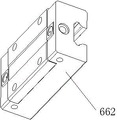
As a further preferable means, the moving mechanism comprises an i-shaped sliding column and sliding blocks which are matched with the i-shaped sliding column and provided with inner notches, the i-shaped sliding column is arranged on two sides of the jig mounting plate in a bilateral symmetry mode, the sliding blocks with the inner notches are fixed on the steel sheet jig frame through bolts, the sliding blocks with the inner notches are sleeved on the i-shaped sliding column and can move up and down, and a first blocking column which is used for blocking the sliding blocks with the inner notches from sliding out of the i-shaped sliding column is arranged below the steel sheet jig frame.
As a further preferred means, the steel sheet jig frame comprises jig columns and a cross rod used for installing the jig columns, the sliding blocks with the inner notches are fixed on the cross rod, the jig columns are vertically arranged on the cross rod at equal intervals, and when the cross rod abuts against the first blocking column, the top ends of the jig columns are higher than the horizontal height of the movable block installing frame.
As a further preferable means, a second driving cylinder and a second retaining post are arranged below the seal strip jig mechanism, when the servo motor moves the steel sheet jig frame to the position below the seal strip jig mechanism, the bottom end of the steel sheet jig frame is overlapped on the first retaining post and the second retaining post, and the second driving cylinder pushes the steel sheet jig frame to move upwards.
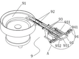
As a further preferable means, the steel sheet transportation mechanism comprises a steel sheet vibration disc, a steel sheet transportation track and a steel sheet loading jig structure, one end of the steel sheet transportation track is connected into the steel sheet vibration disc, the other end of the steel sheet transportation track is connected into the steel sheet loading jig structure, and the steel sheet loading jig structure loads the steel sheet transported by the steel sheet transportation track into the steel sheet jig carrying mechanism.
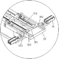
As a further preferable means, the steel sheet loading jig structure comprises a loading plate, a steel sheet moving block, a third cylinder and a fourth cylinder, wherein the loading plate is provided with a transverse sliding groove and a longitudinal sliding groove, a cylinder shaft of the third cylinder is fixedly connected with one end of the steel sheet moving block and pushes the steel sheet moving block to move in the transverse sliding groove, a steel sheet pushing plate is fixedly mounted on a cylinder shaft of the fourth cylinder, the fourth cylinder pushes the steel sheet pushing plate to move in the longitudinal sliding groove, a steel sheet transportation track is connected into the transverse sliding groove and communicated with the transverse sliding groove, and a steel sheet placing notch is formed in the steel sheet moving block.
As a further preferable means, a steel sheet anti-slip rod is fixedly installed below the seal placing table, one end of the steel sheet anti-slip rod extends outwards to the outer edge of the seal placing table, the other end of the steel sheet anti-slip rod extends beside the loading plate and is attached to the loading plate, and the side edge of the steel sheet anti-slip rod and the side edge of the loading plate are located on the same plane.
As a further preferable means, the steel sheet transportation track and the steel sheet loading jig structure can be symmetrically provided with two steel sheet loading jig structures, and one loading plate can be adopted as the two steel sheet loading jig structures.
The invention has the following beneficial effects: according to the invention, only the seal is manually placed on the seal jig mechanism, the seal pressing mechanism presses the seal, the steel sheet vibrating disc in the equipment performs spiral vibration on the steel sheet, the installation direction of the steel sheet (lock cylinder) is selected, after the steel sheet is screened, the steel sheet is conveyed to the position of the seal through the steel sheet conveying mechanism, the steel sheet jig carrying mechanism and the seal jig mechanism, and then the steel sheet is pushed into the seal through the pin inserting mechanism, so that the assembly and installation of the lock cylinder of the sealing lock are completed. The whole process automation degree is high, and the steel sheet delivery speed is fast, and the degree of accuracy is high, and the installation is executed and is sealed the efficient of lock core to realize that the automation has replaced the manual mode of accomplishing of traditional manual work, effectively improved production operating efficiency, and the manpower that significantly reduces consumes, reduce the cost of labor, can also guarantee product equipment quality simultaneously, be worth mill batch using widely.
Drawings
Fig. 1 is a schematic view of the overall structure of an automatic locking lock cylinder assembling device of the invention.
Fig. 2 is a schematic structural view of a seal jig mechanism according to the present invention.
Fig. 3 is a schematic structural view of a seal placing table according to the present invention.
Fig. 4 is a schematic structural view of the seal stabilizing block of the present invention.
Fig. 5 is a schematic structural view of the seal of the present invention.
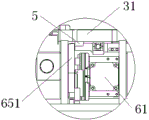
Fig. 6 is a schematic structural view of the factory-shaped mounting frame, and the seal pressing mechanism and the pin inserting mechanism mounted on the factory-shaped mounting frame according to the present invention.
Fig. 7 is a left side view of fig. 6.
Fig. 8 is a schematic structural view of the steel jig carrying mechanism of the present invention.
Fig. 9 is a schematic diagram of the movable block structure of the present invention.
Fig. 10 is a schematic structural view of a jig mounting plate according to the present invention.
Fig. 11 is a schematic structural view of an i-shaped strut of the present invention.
FIG. 12 is a schematic view of the slider with internal notches of the present invention.
FIG. 13 is a schematic structural view of a steel sheet conveying mechanism of the present invention.
Fig. 14 is an enlarged view of a portion a in fig. 13.
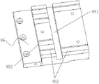
Fig. 15 is a schematic structural view of the loading plate of the present invention.
Fig. 16 is a schematic structural view of the sheet moving block of the present invention.
Fig. 17 is an enlarged schematic view of the seal placement table in the right side view of fig. 1.
FIG. 18 is an enlarged view of the loading plate of FIG. 1.
In the figure: 1. a controller; 2. a seal pressing mechanism; 21. a first driving cylinder; 22. a stabilization post; 23. a pressing plate; 24. a pressing block; 3. a seal jig mechanism; 31. a seal placing table; 311. a pin slot; 3111. a shallow groove area; 3112. a deep groove region; 312. inserting an opening of a steel sheet jig; 32. clamping the strip; 321. opening the gap; 33. a seal stabilizing block; 331. a friction portion; 4. a seal; 41. a hand-held portion; 42. a steel sheet insertion portion; 43. a seal substrate; 5. a steel sheet anti-skid rod; 6. a steel sheet jig carrying mechanism; 61. a servo motor; 62. a movable block mounting frame; 621. a screw rod; 63. a movable block; 631. a screw hole; 632. a movable limiting groove; 64. a jig mounting plate; 65. a steel sheet jig frame; 651. a jig column; 652. a cross bar; 66. a movable mechanism; 661. an I-shaped strut; 662. a slider with an internal recess; 67. a first bumping post; 68. a second driving cylinder; 69. a second bumping post; 7. installing a counter; 8. a factory-shaped mounting rack; 9. a steel sheet conveying mechanism; 91. vibrating a steel disc; 92. a steel sheet transportation rail; 93. a fourth cylinder; 931. a steel sheet push plate; 94. a third cylinder; 941. a steel sheet moving block; 9411. placing a notch on the steel sheet; 95. a loading plate; 951. a transverse chute; 952. a longitudinal chute; 953. a transition groove; a. a pin inserting mechanism; a1, pin insertion; a11, a thin sheet needle; a12, columnar needle body; a2, push rod; a3, and a third driving cylinder.
Detailed Description
The invention is described in further detail below with reference to the accompanying drawings:
referring to fig. 1, the automatic lock cylinder assembly equipment for sealing lock of the invention comprises an installation counter 7, a factory-shaped installation rack 8, a seal jig mechanism 3, a seal pressing mechanism 2, a pin inserting mechanism a, a steel sheet conveying mechanism 9 and a steel sheet jig carrying mechanism 6, the steel sheet conveying mechanism 9, the steel sheet jig carrying mechanism 6 and the seal jig mechanism 3 are sequentially arranged on the mounting counter 7 according to the position relation of stations, the H-shaped mounting rack 8 is arranged on the mounting counter 7, the seal jig mechanism 3 is arranged below the factory-shaped mounting frame 8, the seal pressing mechanism 2 is arranged on the top end frame of the factory-shaped mounting frame 8 and is opposite to the seal jig mechanism 3, a pin inserting mechanism a which pushes the steel sheet to move and enables the steel sheet to be installed on the seal 4 is installed on the side frame of the factory-shaped installation frame 8, and a controller 1 for controlling the operation of the assembling equipment is arranged above the factory-shaped mounting frame 8.
As shown in fig. 5, the seal 4 includes a handle 41, a steel sheet insert 42 and a seal substrate 43, the steel sheet insert 42 is a slot with an opening on one side, the steel sheet can be clamped in the slot, a hole is formed in the middle of the steel sheet insert 42, after the steel sheet is inserted into the slot, the hole on the steel sheet matches with the hole on the steel sheet insert 42, and the end of the seal substrate 43 is inserted into the hole to form a locked sealing lock.
As shown in fig. 2 and 3, the seal fixture mechanism 3 includes a seal placing table 31, two parallel clamping strips 32 disposed on the seal placing table 31 for limiting the position of the seal 4, the clamping strips 32 are fixed on the seal placing table 31 by bolts, steel sheet fixture insertion openings 312 are disposed on one side of the seal placing table 31 away from the factory-shaped mounting rack 8 at equal intervals, openings 321 matched with the steel sheet fixture insertion openings 312 are disposed on one clamping strip 32 close to the steel sheet fixture insertion openings 312 at equal intervals, a seal stabilizing block 33 is embedded in the seal placing table 31 at the position below the openings 321, a plurality of needle insertion grooves 311 are disposed on the seal placing table 31, one end of each needle insertion groove 311 extends to the steel sheet fixture insertion opening 312, and the other end extends to one side of the seal placing table 31 close to the factory-shaped mounting rack 8.
The seal stabilizing block 33 is provided with a friction part 331, the friction part 331 is an area with concave grains, when the seal 4 is placed on the seal jig mechanism 3, the steel sheet insertion part 42 on the seal 4 is placed on the friction part 331, and when the seal pressing mechanism 2 presses the seal 4, because the steel sheet insertion part 42 is in close contact with the friction part 331, and the friction is increased, when the steel sheet is inserted into the steel sheet insertion part 42, the seal 4 cannot shake.
As shown in fig. 6 and 7, the seal pressing mechanism 2 includes a first driving cylinder 21, a pressing plate 23, a pressing block 24, and a stabilizing post 22, the first driving cylinder 21 is disposed above the top end frame of the factory-shaped mounting frame 8, a cylinder shaft of the first driving cylinder 21 passes through the top end frame and extends to the lower side to be fixedly connected with the pressing plate 23, four stabilizing posts 22 are fixedly disposed on the pressing plate 23, the stabilizing posts 22 pass through the top end frame of the factory-shaped mounting frame 8 and can move up and down therein, the pressing blocks 24 are fixed below the pressing plate 23 at equal intervals, each pressing block 24 corresponds to each steel sheet jig insertion opening 312, the pressing block 24 is in a convex shape, and a protruding portion of the pressing block 24 faces the notch 321.
The pin inserting mechanism a comprises a third driving cylinder a3, a push rod a2 and a pin a1, wherein the shaft of the third driving cylinder a3 is installed at the outer side of the side frame of the H-shaped mounting frame 8, the cylinder shaft of the third driving cylinder a3 penetrates through the side frame of the H-shaped mounting frame 8 and is fixedly connected with the push rod a2, the pins a1 are fixed on the push rod a2 at equal intervals, the pins a1 are inserted into the pin grooves 311 and move in the grooves, and the pin heads of the pins a1 can move to the steel sheet jig insertion holes 312.
As shown in fig. 3, the pin slot 311 includes a shallow slot area 3111 and a deep slot area 3112, the outer end of the shallow slot area 3111 is connected to the steel sheet fixture socket 312, the outer end of the deep slot area 3112 is disposed at the side of the seal placing table 31, the pin a1 includes a thin-sheet pin a11 and a cylindrical pin a12, the thickness of the thin-sheet pin a11 matches the depth of the shallow slot area 3111, and the thickness of the cylindrical pin a12 matches the depth of the deep slot area 3112. The thin sheet needle a11 is put in the thickness corresponding to the thickness of the steel sheet. When the pin a1 is inserted into the pin slot 311 and the cylinder pin a12 contacts the end of the deep slot 3112, the thin sheet pin a11 just pushes the steel sheet to insert into the steel sheet insertion portion 42.
Referring to fig. 8-12, the steel jig carrying mechanism 6 includes a servo motor 61, a steel jig frame 65, a jig mounting plate 64, a movable block 63, and a movable block mounting frame 62, one end of the movable block mounting frame 62 is connected with the servo motor 61, a screw 621 is arranged in the movable block mounting frame 62, one end of the screw 621 penetrates through one end of the movable block mounting frame 62 to be connected with the shaft of the servo motor 61, the other end of the screw 621 is inserted into the end face of the other end of the movable block mounting frame 62, a screw hole 631 is arranged on the horizontal axis of the middle position of the movable block 63, sliding limit grooves are symmetrically arranged on the upper side and the lower side of the movable block 63, the screw rod 621 is inserted into the screw hole 631, and the movable limiting groove 632 on the movable block 63 is clamped on the upper and lower frame edges of the movable block mounting frame 62, the jig mounting plate 64 is fixed on the movable block 63 through bolts, and the steel sheet jig frame 65 is movably connected with the jig mounting plate 64 through a movable mechanism 66. Moving mechanism 66 includes I shape traveller 661 and the slider 662 that has an interior notch that matches with I shape traveller 661, I shape traveller 661 bilateral symmetry sets up in tool mounting panel 64 both sides, slider 662 that has an interior notch passes through the bolt fastening on steel sheet tool frame 65, slider 662 that has an interior notch overlaps on I shape traveller 661 and can reciprocate, steel sheet tool frame 65 below is equipped with the first bumping post 67 that is used for blocking slider 662 roll-off I shape traveller 661 that has an interior notch.
The steel sheet jig frame 65 comprises jig columns 651 and a cross rod 652 used for installing the jig columns 651, the sliding blocks 662 with the inner notches are fixed on the cross rod 652, the jig columns 651 are vertically arranged on the cross rod 652 at equal intervals, and when the cross rod 652 abuts against the first blocking column 67, the top ends of the jig columns 651 are higher than the horizontal height of the movable block installation frame 62.
A second driving cylinder 68 and a second blocking column 69 are arranged below the seal jig mechanism 3, when the servo motor 61 moves the steel sheet jig frame 65 to the lower side of the seal jig mechanism 3, the bottom end of the steel sheet jig frame 65 is arranged on the first blocking column 67 and the second blocking column 69 in an overlapping mode, and the second driving cylinder 68 pushes the steel sheet jig frame 65 to move upwards.
As shown in fig. 13-16, the steel sheet transportation mechanism 9 includes a steel sheet vibration disc 91, a steel sheet transportation rail 92, and a steel sheet loading jig structure, wherein one end of the steel sheet transportation rail 92 is connected into the steel sheet vibration disc 91, and the other end is connected into the steel sheet loading jig structure, and the steel sheet loading jig structure loads the steel sheet transported by the steel sheet transportation rail 92 into the steel sheet jig transportation mechanism.
The steel sheet loads into tool structure is including carrying into board 95, steel sheet movable block 941, third cylinder 94 and fourth cylinder 93, carry into and be equipped with horizontal spout 951 and longitudinal sliding groove 952 on the board 95, the cylinder shaft of third cylinder 94 and steel sheet movable block 941 one end fixed connection and promote steel sheet movable block 941 and remove in horizontal spout 951, the epaxial fixed mounting of cylinder of fourth cylinder 93 has steel sheet push pedal 931, fourth cylinder 93 promotes steel sheet push pedal 931 and removes in longitudinal sliding groove 952, steel sheet transportation track 92 inserts horizontal spout 951 and communicates with each other with it, it places notch 9411 to be equipped with the steel sheet on the steel sheet 941. The loading plate 95 is provided with a transition groove 953 for transferring the steel sheet to the transverse sliding groove 951.
When the steel sheet jig frame 65 moves to the side of the loading plate 95 and the jig column 651 just moves to the side of the longitudinal sliding groove 952, the steel sheet on the steel sheet moving block 941 is pushed by the third cylinder 94 to push the steel sheet pushing plate 931 to move into the jig of the jig column 651 in the longitudinal sliding groove 952.
As shown in fig. 17 to 18, a steel sheet anti-slip rod 5 is fixedly installed below the seal placing table 31, one end of the steel sheet anti-slip rod 5 extends outward to the outer edge of the seal placing table 31, the other end extends to and is attached to the side of the loading plate 95, and the side of the steel sheet anti-slip rod 5 and the side of the loading plate 95 are located on the same plane.
The steel sheet tool frame 65 and the shell wall tightly cling to each other, when the tool column 651 on the steel sheet tool frame 65 moves to the side of the loading plate 95 and is loaded with the steel sheet, the top end (loaded with the steel sheet) of the tool column 651 can enter a tunnel formed by the steel sheet anti-slip rod 5 and the shell wall, the tool column 65 moves in the tunnel and moves to the lower side of the seal strip tool mechanism 3, and the top end of the tool column 65 is opposite to the steel sheet tool socket 312. The jig column 65 moves in the tunnel without causing the steel sheet to slide out of the steel sheet jig.
The steel sheet transportation rail 92 and the steel sheet loading jig structure can be symmetrically provided with two steel sheet transportation rail structures, and the two steel sheet loading jig structures can adopt one loading plate 95.
The width of the left and right parts of the equipment is 900mm, the depth of the front and back parts is 550mm, and the height of the equipment is 1300 mm. The total weight is about 150 KG. The working voltage is 220V, 1KW and the air pressure is more than 0.3 MPA.
The working principle is as follows: placing a steel sheet into the steel sheet vibrating disc 91, placing a seal 4 on a seal jig mechanism 3, namely the position of a seal placing table 31, wherein a steel sheet inserting part 42 faces downwards and is clamped in a notch 321, then opening a controller 1 (a PLC controller), starting the seal pressing mechanism 2 to work, pressing a convex pressing block 24 on the seal 4, wherein the convex part of the pressing block 24 is opposite to the notch 321, starting the steel sheet vibrating disc 91 to work, spirally vibrating the steel sheet to a steel sheet conveying track 92, enabling the steel sheet to enter a steel sheet inlet of a loading plate 95 from the steel sheet conveying track 92 and enter a steel sheet placing notch 9411 on a steel sheet moving block 941 in a transverse sliding groove 951, pulling a steel sheet moving block 941 by a third air cylinder 94 to enable the steel sheet placing notch 9411 to just move to the position of the longitudinal sliding groove 952, pushing a push plate to move along the longitudinal sliding groove 952 by an air cylinder 931 by a shaft of a fourth air cylinder 93, the servo motor 61 drives the first jig column 651 on the steel sheet jig frame 65 to move to the notch position of the longitudinal sliding groove 952 (if two steel sheet transportation rails 92 are arranged and the steel sheet loading jig structure is arranged, the first and second jig columns 651 do not move to the notch positions of the two longitudinal sliding grooves 952), the jig of the steel sheet is just aligned with the notch, the steel sheet is pushed onto the steel sheet jig by the steel sheet pushing plate 931, then the servo motor 61 drives the steel sheet jig frame 65 to move forwards to carry out the work of loading other jig columns 651 into the steel sheet, when the jig columns 651 are all loaded with the steel sheet, the servo motor 61 moves the steel sheet jig frame 65 to the lower part of the seal jig mechanism 3, the top ends of the jig columns 65 move in the tunnel formed by the steel sheet antiskid rod 5 and the shell wall, when the top end of each jig column 65 just aligns with the corresponding steel sheet jig socket 312 (at this time, the cross rod 652 just puts on the first blocking column 67 and the second blocking column 69), the second driving cylinder 68 drives the cross rod 652 to move upwards, so that the jig column 65 is inserted into the steel sheet jig socket 312, the steel sheet on the jig column 65 is just flush with the shallow slot area 3111, at this time, the pin inserting mechanism a pushes the pin a1 to move from the pin inserting slot 311, the needle head moves to the steel sheet, and continues to push the steel sheet, so that the steel sheet enters the steel sheet inserting part 42, the installation of the lock cylinder of the sealing lock is completed, and then the next group of operations are completed according to the above process.
It will be evident to those skilled in the art that the invention is not limited to the details of the foregoing illustrative embodiments, and that the present invention may be embodied in other specific forms without departing from the spirit or essential attributes thereof. The present embodiments are therefore to be considered in all respects as illustrative and not restrictive, the scope of the invention being indicated by the appended claims rather than by the foregoing description, and all changes which come within the meaning and range of equivalency of the claims are therefore intended to be embraced therein.
Furthermore, it should be understood that although the present description refers to embodiments, not every embodiment may contain only a single embodiment, and such description is for clarity only, and those skilled in the art should integrate the description, and the embodiments may be combined as appropriate to form other embodiments understood by those skilled in the art.
The present invention is not limited to the above description of the embodiments, and those skilled in the art should, in light of the present disclosure, appreciate that many changes and modifications can be made without departing from the spirit and scope of the invention.
Claims (7)
1. The utility model provides an automatic change and execute blockade lock core rigging equipment which characterized in that: the sealing strip pressing mechanism (2) is installed on a top frame of the factory-shaped mounting rack (8) and is right opposite to the sealing strip fixture mechanism (3), a pin inserting mechanism (a) for pushing the steel sheet to move and enabling the steel sheet to be installed on the sealing strip (4) is installed on a side frame of the factory-shaped mounting rack (8), a controller (1) for controlling the operation of the assembly equipment is arranged above the factory-shaped mounting frame (8);
the seal jig mechanism (3) comprises a seal placing table (31), two parallel clamping strips (32) arranged on the seal placing table (31) for limiting the position of the seal (4), the clamping strips (32) are fixed on the seal placing table (31) through bolts, steel sheet fixture inserting holes (312) are arranged on one side edge of the seal placing table (31) far away from the factory-shaped mounting rack (8) at equal intervals, a clamping strip (32) close to the steel sheet jig insertion opening (312) is provided with notches (321) matched with the steel sheet jig insertion opening (312) at equal intervals, a seal strip stabilizing block (33) is embedded in the seal strip placing table (31) below the notch (321), a plurality of pin grooves (311) are formed in the seal placing table (31), one end of each pin groove (311) extends to a steel sheet jig insertion opening (312), and the other end of each pin groove extends to one side edge of the seal placing table (31) close to the factory-shaped mounting rack (8);
the steel sheet tool carrying mechanism (6) comprises a servo motor (61), a steel sheet tool frame (65), a tool mounting plate (64), a movable block (63) and a movable block mounting frame (62), one end of the movable block mounting frame (62) is connected with the servo motor (61), a lead screw (621) is arranged in the movable block mounting frame (62), one end of the lead screw (621) penetrates through one end of the movable block mounting frame (62) and is connected with a shaft of the servo motor (61), the other end of the lead screw (621) is inserted into the end face of the other end of the movable block mounting frame (62), a screw hole (631) is formed in the horizontal axis of the middle position of the movable block (63), sliding limiting grooves are symmetrically formed in the upper side edge and the lower side edge of the movable block mounting frame (62) at the upper side and the lower side edges of the movable block mounting frame (62) of the lead screw (621) are inserted into the screw hole (631), and the movable limiting grooves (632) in the movable block (63) are clamped on the movable block, the jig mounting plate (64) is fixed on the movable block (63) through bolts, and the steel sheet jig frame (65) is movably connected with the jig mounting plate (64) through a movable mechanism (66);
a second driving cylinder (68) and a second retaining column (69) are arranged below the seal jig mechanism (3), when the servo motor (61) moves the steel sheet jig frame (65) to the position below the seal jig mechanism (3), the bottom end of the steel sheet jig frame (65) is overlapped on the first retaining column (67) and the second retaining column (69), and the second driving cylinder (68) pushes the steel sheet jig frame (65) to move upwards;
the steel sheet conveying mechanism (9) comprises a steel sheet vibration disc (91), a steel sheet conveying track (92) and a steel sheet loading jig structure, one end of the steel sheet conveying track (92) is connected into the steel sheet vibration disc (91), the other end of the steel sheet conveying track is connected into the steel sheet loading jig structure, and the steel sheet loading jig structure loads the steel sheet conveyed by the steel sheet conveying track (92) into the steel sheet jig carrying mechanism;
the steel sheet loading jig structure comprises a loading plate (95), a steel sheet moving block (941), a third air cylinder (94) and a fourth air cylinder (93), wherein a transverse sliding groove (951) and a longitudinal sliding groove (952) are formed in the loading plate (95), an air cylinder shaft of the third air cylinder (94) is fixedly connected with one end of the steel sheet moving block (941) and pushes the steel sheet moving block (941) to move in the transverse sliding groove (951), an air cylinder shaft of the fourth air cylinder (93) is fixedly provided with a steel sheet push plate (931), the fourth air cylinder (93) pushes the steel sheet push plate (931) to move in the longitudinal sliding groove (952), a steel sheet conveying track (92) is connected into the transverse sliding groove (951) and communicated with the transverse sliding groove, and a steel sheet placing notch (9411) is formed in the steel sheet moving block (941);
the sealing strip placing table is characterized in that a steel sheet anti-slip rod (5) is fixedly mounted below the sealing strip placing table (31), one end of the steel sheet anti-slip rod (5) extends outwards to the outer edge of the sealing strip placing table (31), the other end of the steel sheet anti-slip rod extends to the side of the loading plate (95) and is attached to the loading plate, and the side edge of the steel sheet anti-slip rod (5) and the side edge of the loading plate (95) are located on the same plane.
2. An automated lock cylinder assembly machine according to claim 1, characterized in that: the seal pressing mechanism (2) comprises a first driving cylinder (21), a pressing plate (23), pressing blocks (24) and stabilizing columns (22), wherein the first driving cylinder (21) is arranged above a top end frame of the factory-shaped mounting frame (8), a cylinder shaft of the first driving cylinder (21) penetrates through the top end frame to extend to the lower side to be fixedly connected with the pressing plate (23), four stabilizing columns (22) are fixedly arranged on the pressing plate (23), the stabilizing columns (22) penetrate through the top end frame of the factory-shaped mounting frame (8) and can move up and down in the factory-shaped mounting frame, the pressing blocks (24) are fixed below the pressing plate (23) at equal intervals, each pressing block (24) corresponds to each steel sheet fixture insertion opening (312), the pressing blocks (24) are in a convex shape, and the convex parts of the pressing blocks (24) are opposite to the notches (321).
3. An automated lock cylinder assembly machine according to claim 1, characterized in that: the pin inserting mechanism (a) comprises a third driving cylinder (a3), a push rod (a2) and a pin (a1), wherein the shaft of the third driving cylinder (a3) is installed on the outer side of a side frame of the H-shaped mounting frame (8), the cylinder shaft of the third driving cylinder (a3) penetrates through the side frame of the H-shaped mounting frame (8) and is fixedly connected with the push rod (a2), the pin (a1) is fixed on the push rod (a2) at equal intervals, the pin (a1) is inserted into a pin inserting groove (311) and moves in the groove, and the pin head of the pin (a1) can move to the steel sheet jig inserting opening (312).
4. An automated lock cylinder assembly machine according to claim 3, characterized in that: the contact pin groove (311) includes shallow groove district (3111) and deep groove district (3112), the outer end and steel sheet tool socket (312) of shallow groove district (3111) meet, the side of platform (31) is placed at the seal to the outer end setting of deep groove district (3112), contact pin (a1) includes thin slice syringe needle (a11) and column needle body (a12), the thickness of thin slice syringe needle (a11) and the degree of depth phase-match of shallow groove district (3111), the thickness of column needle body (a12) and the degree of depth phase-match of deep groove district (3112).
5. An automated lock cylinder assembly machine according to claim 1, characterized in that: moving mechanism (66) include I shape traveller (661) and have interior notched slider (662) with I shape traveller (661) matching, I shape traveller (661) bilateral symmetry sets up in tool mounting panel (64) both sides, slider (662) that have interior notch pass through the bolt fastening on steel sheet tool frame (65), slider (662) cover that have interior notch is on I shape traveller (661) and can reciprocate, steel sheet tool frame (65) below is equipped with and is used for blocking slider (662) roll-off I shape traveller (661) that have interior notch first fender post (67).
6. An automated lock cylinder assembly machine according to claim 5, characterized in that: the steel sheet tool frame (65) comprises tool columns (651) and cross rods (652) used for installing the tool columns (651), the sliding blocks (662) with inner notches are fixed on the cross rods (652), the tool columns (651) are vertically arranged on the cross rods (652) at equal intervals, and when the cross rods (652) abut against the first blocking columns (67), the top ends of the tool columns (651) are higher than the horizontal height of the movable block installing frame (62).
7. An automated lock cylinder assembly machine according to claim 1, characterized in that: the steel sheet transportation track (92) and the steel sheet loading jig structure are symmetrically provided with two steel sheet loading jig structures, and one loading plate (95) is adopted in the two steel sheet loading jig structures.
Priority Applications (1)
| Application Number | Priority Date | Filing Date | Title |
|---|---|---|---|
| CN201910256651.XA CN111761834B (en) | 2019-04-01 | 2019-04-01 | Automatic change and execute blockade lock core rigging equipment |
Applications Claiming Priority (1)
| Application Number | Priority Date | Filing Date | Title |
|---|---|---|---|
| CN201910256651.XA CN111761834B (en) | 2019-04-01 | 2019-04-01 | Automatic change and execute blockade lock core rigging equipment |
Publications (2)
| Publication Number | Publication Date |
|---|---|
| CN111761834A CN111761834A (en) | 2020-10-13 |
| CN111761834B true CN111761834B (en) | 2022-03-29 |
Family
ID=72718699
Family Applications (1)
| Application Number | Title | Priority Date | Filing Date |
|---|---|---|---|
| CN201910256651.XA Active CN111761834B (en) | 2019-04-01 | 2019-04-01 | Automatic change and execute blockade lock core rigging equipment |
Country Status (1)
| Country | Link |
|---|---|
| CN (1) | CN111761834B (en) |
Families Citing this family (1)
| Publication number | Priority date | Publication date | Assignee | Title |
|---|---|---|---|---|
| CN114789221A (en) * | 2022-05-07 | 2022-07-26 | 黄山亿利工贸集团有限公司 | Steel wire strip of paper used for sealing lock core assembly riveting integrative equipment |
Citations (10)
| Publication number | Priority date | Publication date | Assignee | Title |
|---|---|---|---|---|
| WO1996012654A1 (en) * | 1994-10-20 | 1996-05-02 | American Casting And Manufacturing Corporation | Tamper-proof cargo seal |
| WO2010018117A1 (en) * | 2008-08-12 | 2010-02-18 | Precintia International, S. A. | Seal and process for its manufacturing |
| CN102756272A (en) * | 2012-06-27 | 2012-10-31 | 蚌埠市施封锁有限公司 | Automatic dispensable lock assembling machine |
| CN102756068A (en) * | 2012-06-27 | 2012-10-31 | 蚌埠市施封锁有限公司 | Rivet pre-pressing mechanism of automatic disposable lock assembling machine |
| CN202639825U (en) * | 2012-06-27 | 2013-01-02 | 蚌埠市施封锁有限公司 | Automatic assembling machine for disposable locks |
| CN104707915A (en) * | 2015-02-16 | 2015-06-17 | 上海新帆实业股份有限公司 | Automatic high-security-seal lock cylinder riveting and detecting machine and control method thereof |
| CN104708808A (en) * | 2015-01-26 | 2015-06-17 | 上海新帆实业股份有限公司 | Plastic seal automatic welding and code printing apparatus and control method thereof |
| CN104802395A (en) * | 2015-05-07 | 2015-07-29 | 上海新帆实业股份有限公司 | Automatic assembling and welding machine for high-security bolt seals |
| CN207388323U (en) * | 2017-09-21 | 2018-05-22 | 东莞市典航自动化设备科技有限公司 | Plastic paper strip seal assembles hot coiling machine automatically |
| CN109531133A (en) * | 2019-01-17 | 2019-03-29 | 浙江炬达机械有限公司 | Lock core circlip automatic assembling machine |
-
2019
- 2019-04-01 CN CN201910256651.XA patent/CN111761834B/en active Active
Patent Citations (11)
| Publication number | Priority date | Publication date | Assignee | Title |
|---|---|---|---|---|
| WO1996012654A1 (en) * | 1994-10-20 | 1996-05-02 | American Casting And Manufacturing Corporation | Tamper-proof cargo seal |
| WO2010018117A1 (en) * | 2008-08-12 | 2010-02-18 | Precintia International, S. A. | Seal and process for its manufacturing |
| ES2370543A1 (en) * | 2008-08-12 | 2011-12-19 | Precintia Internacional, S.A. | Seal and process for its manufacturing |
| CN102756272A (en) * | 2012-06-27 | 2012-10-31 | 蚌埠市施封锁有限公司 | Automatic dispensable lock assembling machine |
| CN102756068A (en) * | 2012-06-27 | 2012-10-31 | 蚌埠市施封锁有限公司 | Rivet pre-pressing mechanism of automatic disposable lock assembling machine |
| CN202639825U (en) * | 2012-06-27 | 2013-01-02 | 蚌埠市施封锁有限公司 | Automatic assembling machine for disposable locks |
| CN104708808A (en) * | 2015-01-26 | 2015-06-17 | 上海新帆实业股份有限公司 | Plastic seal automatic welding and code printing apparatus and control method thereof |
| CN104707915A (en) * | 2015-02-16 | 2015-06-17 | 上海新帆实业股份有限公司 | Automatic high-security-seal lock cylinder riveting and detecting machine and control method thereof |
| CN104802395A (en) * | 2015-05-07 | 2015-07-29 | 上海新帆实业股份有限公司 | Automatic assembling and welding machine for high-security bolt seals |
| CN207388323U (en) * | 2017-09-21 | 2018-05-22 | 东莞市典航自动化设备科技有限公司 | Plastic paper strip seal assembles hot coiling machine automatically |
| CN109531133A (en) * | 2019-01-17 | 2019-03-29 | 浙江炬达机械有限公司 | Lock core circlip automatic assembling machine |
Also Published As
| Publication number | Publication date |
|---|---|
| CN111761834A (en) | 2020-10-13 |
Similar Documents
| Publication | Publication Date | Title |
|---|---|---|
| CN106826168A (en) | The assembling feed mechanism of automobile door stop main part assembly machine | |
| CN111761834B (en) | Automatic change and execute blockade lock core rigging equipment | |
| CN105563819A (en) | Magnetic snap continuous production device | |
| CN205395159U (en) | Continuous production unit is detained to magnetism | |
| CN209396548U (en) | A kind of loading and unloading of fully-automatic intelligent production line and material conveying device | |
| CN209738156U (en) | Automatic equipment for shoulder injection of tubular objects | |
| CN108987093B (en) | Iron core hinged workpiece assembling equipment and assembling method thereof | |
| CN108188473B (en) | Automatic groove broacher for lock cylinder and groove broacher process of automatic groove broacher | |
| CN105252588A (en) | Full-automatic production line for LED lamp support | |
| CN206839533U (en) | Intercooler pipes inner fin automatic assembling machine | |
| CN205835606U (en) | A kind of Recombined bamboo cyclic pressing device | |
| CN205835609U (en) | A kind of mould running fix device in Recombined bamboo cyclic pressing mechanism | |
| CN205835608U (en) | A kind of mould adapting device in Recombined bamboo cyclic pressing device | |
| CA1319812C (en) | Reinforcement of moulded construction products | |
| CN205835607U (en) | A kind of Recombined bamboo auxiliary device for pressing | |
| CN212891785U (en) | Tractor rear axle assembly supporting seat | |
| CN214353938U (en) | Automatic blank head device | |
| CN110789050A (en) | Zipper puller tail injection production equipment | |
| CN216229439U (en) | Hardware accurate positioning grabbing device | |
| CN2183232Y (en) | Improved die for making cramp iron | |
| CN204999207U (en) | Special machine of transporting of plastics line type material for building | |
| CN219093329U (en) | Automatic feeding and cutting device for production of engine coil sensor | |
| CN214297770U (en) | Auxiliary structure for assembling conveying chain plate | |
| CN216775248U (en) | Diamond micropowder automatic sorting machine | |
| CN207968237U (en) | A kind of double-station motor stator part forming unit |
Legal Events
| Date | Code | Title | Description |
|---|---|---|---|
| PB01 | Publication | ||
| PB01 | Publication | ||
| SE01 | Entry into force of request for substantive examination | ||
| SE01 | Entry into force of request for substantive examination | ||
| GR01 | Patent grant | ||
| GR01 | Patent grant |