CN109501115B - Feeding and discharging system of injection molding machine - Google Patents
Feeding and discharging system of injection molding machine Download PDFInfo
- Publication number
- CN109501115B CN109501115B CN201811210233.9A CN201811210233A CN109501115B CN 109501115 B CN109501115 B CN 109501115B CN 201811210233 A CN201811210233 A CN 201811210233A CN 109501115 B CN109501115 B CN 109501115B
- Authority
- CN
- China
- Prior art keywords
- group
- clamping
- finished plastic
- plastic parts
- feeding
- Prior art date
- Legal status (The legal status is an assumption and is not a legal conclusion. Google has not performed a legal analysis and makes no representation as to the accuracy of the status listed.)
- Active
Links
Images


Classifications
-
- B—PERFORMING OPERATIONS; TRANSPORTING
- B29—WORKING OF PLASTICS; WORKING OF SUBSTANCES IN A PLASTIC STATE IN GENERAL
- B29C—SHAPING OR JOINING OF PLASTICS; SHAPING OF MATERIAL IN A PLASTIC STATE, NOT OTHERWISE PROVIDED FOR; AFTER-TREATMENT OF THE SHAPED PRODUCTS, e.g. REPAIRING
- B29C45/00—Injection moulding, i.e. forcing the required volume of moulding material through a nozzle into a closed mould; Apparatus therefor
- B29C45/14—Injection moulding, i.e. forcing the required volume of moulding material through a nozzle into a closed mould; Apparatus therefor incorporating preformed parts or layers, e.g. injection moulding around inserts or for coating articles
- B29C45/14008—Inserting articles into the mould
-
- B—PERFORMING OPERATIONS; TRANSPORTING
- B29—WORKING OF PLASTICS; WORKING OF SUBSTANCES IN A PLASTIC STATE IN GENERAL
- B29C—SHAPING OR JOINING OF PLASTICS; SHAPING OF MATERIAL IN A PLASTIC STATE, NOT OTHERWISE PROVIDED FOR; AFTER-TREATMENT OF THE SHAPED PRODUCTS, e.g. REPAIRING
- B29C45/00—Injection moulding, i.e. forcing the required volume of moulding material through a nozzle into a closed mould; Apparatus therefor
- B29C45/17—Component parts, details or accessories; Auxiliary operations
- B29C45/1769—Handling of moulded articles or runners, e.g. sorting, stacking, grinding of runners
-
- B—PERFORMING OPERATIONS; TRANSPORTING
- B29—WORKING OF PLASTICS; WORKING OF SUBSTANCES IN A PLASTIC STATE IN GENERAL
- B29C—SHAPING OR JOINING OF PLASTICS; SHAPING OF MATERIAL IN A PLASTIC STATE, NOT OTHERWISE PROVIDED FOR; AFTER-TREATMENT OF THE SHAPED PRODUCTS, e.g. REPAIRING
- B29C45/00—Injection moulding, i.e. forcing the required volume of moulding material through a nozzle into a closed mould; Apparatus therefor
- B29C45/17—Component parts, details or accessories; Auxiliary operations
- B29C45/38—Cutting-off equipment for sprues or ingates
- B29C45/382—Cutting-off equipment for sprues or ingates disposed outside the mould
-
- B—PERFORMING OPERATIONS; TRANSPORTING
- B29—WORKING OF PLASTICS; WORKING OF SUBSTANCES IN A PLASTIC STATE IN GENERAL
- B29C—SHAPING OR JOINING OF PLASTICS; SHAPING OF MATERIAL IN A PLASTIC STATE, NOT OTHERWISE PROVIDED FOR; AFTER-TREATMENT OF THE SHAPED PRODUCTS, e.g. REPAIRING
- B29C45/00—Injection moulding, i.e. forcing the required volume of moulding material through a nozzle into a closed mould; Apparatus therefor
- B29C45/17—Component parts, details or accessories; Auxiliary operations
- B29C45/40—Removing or ejecting moulded articles
- B29C45/42—Removing or ejecting moulded articles using means movable from outside the mould between mould parts, e.g. robots
-
- B—PERFORMING OPERATIONS; TRANSPORTING
- B29—WORKING OF PLASTICS; WORKING OF SUBSTANCES IN A PLASTIC STATE IN GENERAL
- B29C—SHAPING OR JOINING OF PLASTICS; SHAPING OF MATERIAL IN A PLASTIC STATE, NOT OTHERWISE PROVIDED FOR; AFTER-TREATMENT OF THE SHAPED PRODUCTS, e.g. REPAIRING
- B29C45/00—Injection moulding, i.e. forcing the required volume of moulding material through a nozzle into a closed mould; Apparatus therefor
- B29C45/17—Component parts, details or accessories; Auxiliary operations
- B29C45/1769—Handling of moulded articles or runners, e.g. sorting, stacking, grinding of runners
- B29C2045/177—Handling of moulded articles or runners, e.g. sorting, stacking, grinding of runners stacking moulded articles
Abstract
The invention discloses a feeding and discharging system of an injection molding machine, which comprises a rack, wherein a material receiving device for receiving finished plastic parts, a sheet conveying device for conveying metal connecting sheets, a conveying device for conveying semi-finished plastic parts and a manipulator are arranged on the rack, a plurality of clamping stations capable of clamping the metal connecting sheets, the semi-finished plastic parts and the finished plastic parts respectively are arranged on the manipulator, different clamping stations on the manipulator can correspondingly clamp the metal connecting sheets and the semi-finished plastic parts in sequence to feed the metal connecting sheets and the semi-finished plastic parts into the injection molding machine, the finished plastic parts after injection molding can be taken out and transferred onto the material receiving device, a transferring group capable of carrying empty trays and transferring the empty trays step by step is arranged on the material receiving device, and when the manipulator places the finished plastic parts onto the empty trays, the transferring group can adjust. This application effectively solves many work pieces and gets simultaneously and puts, reduces the last unloading system complexity of going up, improves the last unloading system of unloading efficiency.
Description
Technical Field
The invention relates to the technical field of injection molding equipment, in particular to a feeding and discharging system.
Background
At present, the automobile sensor is generally formed into a semi-finished plastic part in advance, and then is combined with a metal connecting sheet into a whole through secondary injection molding to obtain a final finished product. Because the shapes of the metal connecting sheet, the semi-finished plastic part and the finished plastic part are different, manual feeding is mostly adopted in the injection molding industry, so that the labor cost is high, the working efficiency is low, the labor intensity is high, and industrial injuries are easy to occur.
For this reason some enterprises have designed the manipulator and carried out the material loading, and current injection molding machine mostly adopts the different work pieces of multimanipulator centre gripping respectively to carry out the material loading, because the shape of metal connecting piece, these work pieces of semi-manufactured goods of plastics and finished product working of plastics is different, it is difficult to the work piece of centre gripping different grade type simultaneously to have led to the same manipulator to carry out the material loading, can only adopt many sets of manipulators to carry out the different work pieces of centre gripping and carry out the pay-off, such design often leads to occupation space big, whole cost input, because the last unloading position space of injection molding machine is limited, lead to multimanipulator must move in proper order, holistic work efficiency is still. And at the in-process of unloading behind the manipulator centre gripping completion article working of plastics, generally current pile up neatly device all is the dead position, can carry out the balance according to certain order in order to guarantee the finished product working of plastics, can only adapt to the balance requirement through the unloading position that control unloading manipulator constantly adjusted oneself, lead to the control system who needs to adjust whole unloading manipulator, make the unloading position of finished product working of plastics carry out the balance according to the order, make things convenient for the later stage to be discerned by other equipment and take, this whole control system that obviously can complicate. Therefore, there is a need for a feeding and discharging system that can effectively solve the problem of simultaneously picking and placing multiple workpieces, reduce the complexity of the feeding and discharging system, and improve the feeding and discharging efficiency.
Disclosure of Invention
In order to overcome the defects of the prior art, the invention provides the feeding and discharging system which can effectively solve the problem that multiple workpieces are taken and placed simultaneously, reduce the complexity of the feeding and discharging system and improve the feeding and discharging efficiency.
The technical scheme adopted by the invention for solving the technical problems is as follows:
the utility model provides a go up unloading system of injection molding machine, includes the frame, is equipped with the material collecting device who is used for receiving the finished product working of plastics in the frame, is used for carrying the sheet conveyor of metal connecting piece, is used for carrying the material feeding unit and the manipulator of semi-manufactured goods working of plastics, be provided with a plurality of clamping station that can centre gripping metal connecting piece, semi-manufactured goods working of plastics and finished product working of plastics respectively on the manipulator, the last clamping station that is provided with of manipulator can be in proper order corresponding centre gripping metal connecting piece and semi-manufactured goods working of plastics to the pay-off in the injection molding machine, and can take out and shift the finished product working of plastics that moulds plastics were accomplished and shift to material collecting device on, the last group of transferring that is provided with the transport empty charging tray of transport and progressively shifts empty charging.
As an improvement of the above technical solution, the material receiving device further includes a feeding group for lifting an empty tray, a discharging group for receiving a full tray of workpieces, and a transferring group for receiving finished plastic parts placed by the manipulator, the transferring group can clamp the finished plastic parts and place the finished plastic parts on the empty tray in a preset order, the transferring group is arranged between the feeding group and the discharging group, and the transferring group can clamp and gradually transfer the empty tray from one side of the feeding group to one side of the discharging group to receive the finished plastic parts placed by the transferring group.
As the improvement of above-mentioned technical scheme, the upper end of material loading group and unloading group all is equipped with the opening that makes things convenient for the charging tray business turn over, is provided with the drive slide rail between two sets of openings, but transfer group including slidable mounting on the drive slide rail the carriage with set up the holder in the carriage both sides in opposite directions, the holder of both sides can accept and the chucking material loading group passes the empty charging tray that the opening lifted, or to the unloading group transmission full charging tray, the drive slide rail can drive the carriage reciprocating motion between two sets of openings.
As an improvement of the technical scheme, a feeding box for accommodating and stacking empty trays is arranged in the feeding group, a lifting table for bearing the empty trays is arranged in the feeding box in a lifting manner, and the lifting table can lift the empty trays upwards and convey the empty trays to the transfer group; the feeding group is internally provided with a storage box for stacking full trays and a lifting driving seat which can be arranged in the storage box in a lifting manner, and the lifting driving seat can receive the full trays conveyed by the transferring group.
As the improvement of above-mentioned technical scheme, the group that shifts is including the first receiving station and the first centre gripping hand that are used for receiving the finished product working of plastics of manipulator centre gripping, first centre gripping hand is including being equipped with the first slide rail that sets up between first receiving station and the group of transferring and the first centre gripping head of slidable setting on first slide rail, first centre gripping head liftable is provided with first jack catch.
As an improvement of the technical scheme, the manipulator is provided with a rotatable clamping head, all clamping stations are arranged on the outer side surface of the clamping head along the circumferential direction, and each clamping station comprises an adsorption group for adsorbing a metal connecting sheet, a first clamping group for clamping a semi-finished plastic part and a second clamping group for clamping the finished plastic part.
As the improvement of the technical scheme, the adsorption group comprises an adsorption frame, an adsorption block arranged on the adsorption frame and a profiling adsorption sheet arranged on the adsorption block and matched with the surface of the metal connecting sheet, a cavity communicated with external vacuum equipment is arranged in the adsorption block, adsorption holes communicated with the cavity are formed in the adsorption block and the profiling adsorption sheet.
As the improvement of above-mentioned technical scheme, first centre gripping group and second centre gripping group all include mounting substrate and set up the centre gripping module on mounting substrate, centre gripping module is equipped with die clamping cylinder and sets up the grip block at the die clamping cylinder output, and die clamping cylinder can drive the grip block centre gripping semi-manufactured goods of plastics or finished product working of plastics, the one end of grip block centre gripping is equipped with the groove of dodging semi-manufactured goods working of plastics or finished product working of plastics, still be provided with the mouth of a river chuck that is used for centre gripping finished product working of plastics mouth of a river on the second centre gripping group.
As the improvement of the technical scheme, the sheet conveying device comprises a first vibrating disk, a second clamping hand and a second receiving table matched with a mechanical arm to clamp a metal connecting sheet, wherein the second receiving table is arranged on one side of the output end of the first vibrating disk, the second clamping hand comprises a second sliding rail erected between the first vibrating disk and the second receiving table, a transverse telescopic cylinder slidably arranged on the second sliding rail and a second clamping jaw vertically arranged at the output end of the longitudinal telescopic cylinder, the transverse telescopic cylinder is vertically arranged with the second sliding rail, the second clamping jaw is downwards arranged, and the metal connecting sheet capable of clamping the output end of the first vibrating disk is transferred to the second receiving table.
As the improvement of above-mentioned technical scheme, material feeding unit includes second vibration dish, third centre gripping hand and is used for cooperating the third receiving station of manipulator centre gripping semi-manufactured goods, the third receiving station sets up the one side at second vibration dish output, the third centre gripping hand is including erectting the third slide rail between second vibration dish and third receiving station, and slidable sets up the lift cylinder on the third slide rail and sets up the lift seat at lift cylinder output, the output of lift cylinder sets up downwards, sets up the downward third jack catch of at least two sets of output on the lift seat, still be provided with the regulation cylinder that is used for adjusting all third jack catches mutual interval distance on the lift seat, but the semi-manufactured goods of third jack catch centre gripping second vibration dish output to shift to the third receiving station on through the third slide rail.
The invention has the following beneficial effects:
the loading and unloading system integrates multiple clamping stations on the manipulator, so that when the injection molding machine is loaded at one time, different clamping stations can be utilized to correspondingly clamp different types of workpieces for loading and unloading; the finished plastic part and the water gap in the injection molding machine can be quickly taken out before the metal connecting sheet and the semi-finished plastic part are fed by using the clamping station for clamping the finished plastic part, and then the clamped workpiece can be quickly installed on the injection molding position of the injection molding machine by using the clamping station for clamping the metal connecting sheet and the semi-finished plastic part, so that continuous injection molding is realized, and the feeding and discharging are convenient and reliable. In addition, the conveying group on the material receiving device is utilized to cooperate with the mechanical arm to carry out blanking, and finished plastic pieces are received by conveying the vacancy on the group clamping and adjusting empty charging tray, so that the control difficulty of the whole mechanical arm is reduced, and the blanking of the mechanical arm is facilitated. The whole system integration level from top to bottom is high, the investment of the whole production cost can be effectively reduced, the occupied space is reduced, and the working efficiency is improved.
Drawings
The invention is further described with reference to the following detailed description of embodiments and drawings, in which:
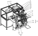
FIG. 1 is a first schematic structural diagram of an embodiment of the present invention;
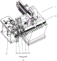
FIG. 2 is a second schematic structural diagram of an embodiment of the present invention;
FIG. 3 is a partial block diagram of an embodiment of the present invention;
FIG. 4 is a second partial schematic structural diagram of an embodiment of the present invention;
FIG. 5 is a first schematic structural diagram of a material receiving device according to an embodiment of the present disclosure;
FIG. 6 is a schematic structural diagram of a material receiving device in an embodiment of the present invention;
FIG. 7 is a schematic view of a robot according to an embodiment of the present invention;
FIG. 8 is a schematic view of the structure of the gripping head in an embodiment of the present invention;
FIG. 9 is a schematic view showing a part of the structure of a sheet conveying apparatus in the embodiment of the present invention;
fig. 10 is a partial structural schematic view of a feeding device in an embodiment of the present invention.
Detailed Description
Referring to fig. 1 to 10, the feeding and discharging system of the injection molding machine is installed on one side of the feeding and discharging of the injection molding machine and used for being matched with the injection molding machine for feeding and discharging. The feeding and discharging system is provided with a rack 1, a material receiving device 2 for receiving finished plastic pieces, a piece conveying device 3 for conveying metal connecting pieces, a feeding device 4 for conveying semi-finished plastic pieces and a manipulator 5 are arranged on the rack 1, the manipulator 5 is provided with a plurality of clamping stations which can respectively clamp the metal connecting sheet, the semi-finished plastic piece and the finished plastic piece, different clamping stations on the manipulator 5 can correspondingly clamp the metal connecting sheet and the semi-finished plastic part in sequence to feed the metal connecting sheet and the semi-finished plastic part into the injection molding machine, and can take out finished plastic pieces after injection molding and transfer the finished plastic pieces to a material receiving device 2, a transfer group 21 which can carry empty trays and transfer the empty trays step by step is arranged on the material receiving device 2, when the manipulator 5 places finished plastic parts on the empty tray, the transfer set 21 can adjust the vacant positions on the empty tray to receive the finished plastic parts. In this application, be provided with rotatable clamping head 51 on the manipulator 5, all centre gripping stations set up on the lateral surface of clamping head 51 along circumference, the centre gripping station is including the absorption group 52 that is used for adsorbing the metal connecting piece, the second centre gripping group 54 that is used for pressing from both sides the first centre gripping group 53 of getting semi-manufactured goods working of plastics and is used for centre gripping finished goods working of plastics. Each clamping station is provided with a corresponding clamping tool, and the clamping tools correspond to the adsorption group 52, the first clamping group 53 and the second clamping group 54 in the application. By using different clamping tools, the metal connecting sheet and the semi-finished plastic part can be clamped simultaneously to be placed in an injection mold of an injection molding machine and a workpiece can be assembled preliminarily during feeding, and then the finished plastic part which is subjected to injection molding is clamped by the second clamping group 54 during feeding to perform feeding. The injection molding machine that uses in cooperation in this application adopts an injection mould, consequently need utilize second centre gripping group 54 centre gripping to accomplish the finished product working of plastics that has already been moulded plastics, also will mould plastics remaining mouth of a river centre gripping together for once clear up and accomplish whole injection mould simultaneously. After the injection mold is cleaned, the adsorption unit 52 and the first clamping unit 53 respectively place the metal connecting sheet and the semi-finished plastic part into the injection mold, and the final feeding is completed. Then the whole manipulator is withdrawn from the injection molding machine, the second clamping group 54 places the clamped finished plastic parts on the material receiving device 2, and in the moving process, the second clamping group 54 loosens the clamped water gap at a specific position to complete the whole blanking process. And at this moment, all the clamping stations on the manipulator 5 are empty, the manipulator 5 moves to the positions of the sheet conveying device 3 and the feeding device 4 in sequence, and the clamping stations installed on the adsorption group 52 and the first clamping group 53 clamp the workpieces provided on the sheet conveying device 3 and the feeding device 4 in sequence, so that the primary feeding is completed.
Referring to fig. 1 to 6, the receiving device 2 further includes a loading group 22 for lifting an empty tray, a discharging group 23 for receiving a full tray of workpieces, and a transferring group 24 for receiving finished plastic parts placed by the robot 5, the transferring group 24 can clamp the finished plastic parts and place them on the empty tray in a predetermined order, the transferring group 21 is disposed between the loading group 22 and the discharging group 23, and the transferring group 21 can clamp and gradually transfer the empty tray from one side of the loading group 22 to one side of the discharging group 23 to receive the finished plastic parts placed by the transferring group 24. In order to reduce the requirement of the movement track of the robot 5, the transfer unit 24 is used to receive the finished plastic parts held by the robot 5, and the main function of the transfer unit 24 is to set the finished plastic parts.
Referring to fig. 5 and 6, the upper ends of the feeding group 22 and the discharging group 23 are provided with openings for facilitating the feeding and discharging of the material trays, a driving slide rail 25 is arranged between the two openings, the transferring group 21 includes a supporting frame 211 slidably mounted on the driving slide rail 25 and holders 212 oppositely arranged on two sides of the supporting frame 211, the holders 212 on two sides can receive and clamp the empty material trays lifted by the feeding group 22 through the openings, or transmit full material trays to the discharging group 23, and the driving slide rail 25 can drive the supporting frame 211 to reciprocate between the two openings. In this application, the supporting frame 211 is sleeved outside the material tray, and the empty material tray on the feeding group 22 or the full material tray to be received by the discharging group 23 all passes through the supporting frame 211 to complete the movement. The two groups of holders 212 are oppositely arranged on the supporting frame 211 respectively, and the two groups of holders 212 are matched with each other to hold the material tray.
In addition, a loading box 221 for accommodating and stacking empty trays is arranged in the loading group 22, a lifting table 222 for bearing the empty trays is arranged in the loading box 221 in a lifting manner, and the lifting table 222 can lift the empty trays upwards and convey the empty trays to the transfer group 21; it can be understood that when empty trays need to be provided to the transfer group 21, the lifting table 222 lifts all the empty trays stacked in the upper bin 221 together, the uppermost empty tray passes through the supporting frame 211 to reach the height capable of being held by the grippers 212, and the grippers 212 on both sides extend out to clamp both sides of the empty tray. The upper material box 221 is internally provided with a lifting slide rail, the lifting table 222 is slidably arranged on the lifting slide rail, and a lifting motor is arranged in the lifting table 222 to drive the lifting motor to move up and down. In order to increase the stability of holding empty trays, in the application, the holder 212 includes a holding cylinder 212a, a holding block 212b and a guide rail 212c, the holding cylinder 212a and the guide rail 212c are both mounted on the support frame 211, the holding block 212b is slidably mounted on the guide rail 212c, and the holding cylinder 212a is connected with the holding block 212b, so that the holding block 212b moves toward or away from the empty trays. In addition, in order to limit the position of the empty tray in the clamping process, a limit block is further arranged on the clamping block 212 b. After the two sets of clamping blocks 212b arranged in opposite directions extend out of the corresponding clamping cylinders 212a, the two sets of clamping blocks 212b respectively extend into the lower side of the empty tray, the lifting table 222 moves downwards, the weight of the empty tray is gradually borne by the two sets of clamping blocks 212b together due to the loss of the supporting force of the lifting table 222, and the clamping cylinders 212a continue to extend out until the two sides of the empty tray abut against the limiting blocks, so that the loading of the empty tray is completed.
In this application, be provided with the storage case 231 that is used for the full charging tray of stack and the lift drive seat 232 of liftable setting in storage case 231 in the lower feed group 23, the full charging tray that group 21 carried can be transferred in the receipt of lift drive seat 232. After the transfer group 24 continuously performs tray swinging and feeding on empty trays clamped by the transfer group 21, the empty trays are gradually changed into full trays, after the transfer group 24 clamps the empty trays and gradually moves to one side of the blanking group 23, the full trays are positioned right opposite to an opening above the blanking group 23, the lifting driving seat 232 is lifted, the uppermost tray in the full trays carried by the lifting driving seat can be abutted to a tray which is just filled with workpieces, after the whole lifting driving seat 232 moves to a certain height, the weight of a new tray completely falls into the uppermost ends of all full trays carried by the lifting driving seat 232, then the clamping cylinders 212a on the two sides shrink, the corresponding clamping block 212b withdraws to the position, and the lifting driving seat 232 integrally descends to avoid the transfer group 21; and after the uppermost heights of all the full material trays are lower than the lowermost height measurement of the transfer group 21, the transfer group 21 is reset, and the full material trays return to the position of the feeding group 22 to continuously clamp new empty material trays for gradual feeding.
Referring to fig. 1 to 4, the transfer group 24 includes a first receiving station 241 for receiving the finished plastic parts clamped by the manipulator 5 and a first clamping hand 242, the first clamping hand 242 includes a first sliding rail 243 disposed between the first receiving station 241 and the transfer group 21 and a first clamping head 244 slidably disposed on the first sliding rail 243, and the first clamping head 244 is provided with a first claw 245 in a lifting manner. Finished plastic parts clamped by the manipulator 5 can be directly placed on the first receiving platform 241, and then the first clamping hand 242 reciprocates on the first slide rail 243, so that in order to avoid overlapping of the finished plastic parts during placement, the movement distance of the first clamping hand 242 on the first slide rail 243 is continuously adjusted, and transverse order arrangement of empty trays is realized. After each transverse distance, the transfer group 21 moves a distance to one side of the blanking group 23, so that the transfer group 24 starts another row of finished plastic part trays.
Referring to fig. 1 to 4, 7 and 8, the adsorption group 52 includes an adsorption frame 521, an adsorption block 522 mounted on the adsorption frame 521, and a profiling adsorption sheet 523 disposed on the adsorption block 522 and engaged with the surface of the metal connection sheet, a cavity communicated with an external vacuum device is disposed in the adsorption block 522, adsorption holes 524 are disposed on both the adsorption block 522 and the profiling adsorption sheet 523, and the adsorption holes 524 are communicated with the cavity. The profiling adsorption piece 523 can clamp a metal connecting piece with a specific shape, the profiling adsorption piece 523 is made of a compressible elastic material, rubber is preferably selected in the application, and the metal connecting piece can be effectively adsorbed by the adsorption block 522 by utilizing the characteristic of the profiling adsorption piece 523.
In the present application, the basic structures of the first clamping group 53 and the second clamping group 54 are similar, and the design is convenient for replacing parts. Wherein, first centre gripping group 53 and second centre gripping group 54 all include mounting substrate 55 and set up the centre gripping module 56 on mounting substrate 55, centre gripping module 56 is equipped with centre gripping cylinder 561 and sets up the grip block 562 at the grip cylinder 561 output, and grip cylinder 561 can drive grip block 562 centre gripping semi-manufactured goods working of plastics or finished product working of plastics, the one end of grip block 562 centre gripping is equipped with the groove of dodging semi-manufactured goods working of plastics or finished product working of plastics. Because the workpieces clamped by the first clamping group 53 and the second clamping group 54 are different, the finished plastic part clamped by the second clamping group 54 is also connected with a water gap, and therefore, the second clamping group 54 is also provided with a water gap clamping head 57 for clamping the water gap of the finished plastic part. The nozzle clamp 57 and the clamping module 56 act simultaneously to clamp the workpiece in the injection mold, and the injection mold automatically cuts off the connection between the nozzle and the finished plastic part after the injection molding process is completed in order to better clamp the nozzle and the finished plastic part.
Referring to fig. 1, 2, 3, 4 and 9, the sheet conveying device 3 includes a first vibration tray 31, a second clamping hand 32 and a second receiving platform 33 for clamping a metal connecting sheet by the manipulator 5, the second receiving platform 33 is disposed at one side of an output end of the first vibration tray 31, the second clamping hand 32 includes a second slide rail 321 erected between the first vibration tray 31 and the second receiving platform 33, a transverse telescopic cylinder 322 slidably disposed on the second slide rail 321, and a second clamping claw 323 vertically disposed at an output end of the longitudinal telescopic cylinder, the transverse telescopic cylinder 322 is disposed perpendicular to the second slide rail 321, the second clamping claw 323 is disposed downward to the connecting sheet, and the metal at the output end of the first vibration tray 31 can be clamped to be transferred to the second receiving platform 33.
Referring to fig. 1, 2, 3, 4 and 10, the feeding device 4 includes a second vibration tray 41, a third clamping hand 42 and a third receiving platform 43 for clamping the semi-finished plastic part in cooperation with the manipulator 5, the third receiving platform 43 is disposed at one side of the output end of the second vibration tray 41, the third clamping hand 42 includes a third slide rail 421 erected between the second vibration tray 41 and the third receiving platform 43, a lifting cylinder 422 slidably disposed on the third slide rail 421 and a lifting seat 423 disposed at the output end of the lifting cylinder 422, the output end of the lifting cylinder 422 is disposed downward, at least two sets of third clamping jaws 424 with downward output ends are disposed on the lifting seat 423, an adjusting cylinder 425 for adjusting the mutual spacing distance between all the third clamping jaws 424 is further disposed on the lifting seat 423, and the third clamping jaws 424 can clamp the semi-finished plastic part at the output end of the second vibration tray 41, and transferred to the third receiving station 43 by the third slide rail 421.
The loading and unloading system integrates multiple clamping stations on the manipulator 5, so that when the injection molding machine is loaded at one time, different clamping stations can be utilized to correspondingly clamp different types of workpieces for loading and unloading; the finished plastic part and the water gap in the injection molding machine can be quickly taken out before the metal connecting sheet and the semi-finished plastic part are fed by using the clamping station for clamping the finished plastic part, and then the clamped workpiece can be quickly installed on the injection molding position of the injection molding machine by using the clamping station for clamping the metal connecting sheet and the semi-finished plastic part, so that continuous injection molding is realized, and the feeding and discharging are convenient and reliable. In addition, the transfer group 21 on the material receiving device 2 is utilized to cooperate with the manipulator 5 to carry out blanking, and finished plastic parts are received by transferring the vacancy on the group 21 clamping and adjusting empty charging tray, so that the control difficulty of the whole manipulator 5 is reduced, and the blanking of the manipulator 5 is facilitated. The whole system integration level from top to bottom is high, the investment of the whole production cost can be effectively reduced, the occupied space is reduced, and the working efficiency is improved.
The above description is only a preferred embodiment of the present invention, but the present invention is not limited to the above embodiments, and the present invention shall fall within the protection scope of the present invention as long as the technical effects of the present invention are achieved by any similar or identical means.
Claims (8)
1. The utility model provides a go up unloading system of injection molding machine which characterized in that: comprises a frame (1), a receiving device (2) for receiving finished plastic parts, a sheet conveying device (3) for conveying metal connecting sheets, a feeding device (4) for conveying semi-finished plastic parts and a manipulator (5) are arranged on the frame (1), a plurality of clamping stations capable of clamping the metal connecting sheets, the semi-finished plastic parts and the finished plastic parts respectively are arranged on the manipulator (5), different clamping stations on the manipulator (5) can correspondingly clamp the metal connecting sheets and the semi-finished plastic parts in sequence to feed the metal connecting sheets and the semi-finished plastic parts into an injection molding machine, the injection molded finished plastic parts can be taken out and transferred onto the receiving device (2), a transferring group (21) capable of carrying an empty tray and gradually transferring the empty tray is arranged on the receiving device (2), and when the manipulator (5) places the finished plastic parts to the empty tray, the transferring group (21) can adjust empty positions on the empty tray to receive the finished plastic parts, the material receiving device (2) further comprises a feeding group (22) used for lifting an empty tray, a discharging group (23) used for receiving a full workpiece tray and a transfer group (24) used for receiving finished plastic parts placed on a manipulator (5), the transfer group (24) can clamp the finished plastic parts and place the finished plastic parts on the empty tray according to a preset order, the transfer group (21) is arranged between the feeding group (22) and the discharging group (23), the transfer group (21) can clamp and gradually transfer the empty tray from one side of the feeding group (22) to one side of the discharging group (23) to receive the finished plastic parts placed on the transfer group (24), openings facilitating the feeding and discharging of the tray are formed in the upper ends of the feeding group (22) and the discharging group (23), a driving slide rail (25) is arranged between the two groups of openings, the transfer group (21) comprises a supporting frame (211) slidably mounted on the driving slide rail (25) and clamping devices (212) oppositely arranged on two sides of the supporting frame (211), the grippers (212) on the two sides can receive and clamp empty trays lifted by the feeding group (22) through the openings or deliver full trays to the discharging group (23), and the driving slide rails (25) can drive the supporting frame (211) to reciprocate between the two groups of openings.
2. The loading and unloading system of an injection molding machine as claimed in claim 1, wherein: a feeding box (221) used for containing and stacking empty trays is arranged in the feeding group (22), a lifting table (222) used for bearing the empty trays is arranged in the feeding box (221) in a lifting mode, and the lifting table (222) can lift the empty trays upwards and convey the empty trays to the transfer group (21); the feeding group (23) is internally provided with a storage box (231) for stacking full trays and a lifting driving seat (232) arranged in the storage box (231) in a lifting way, and the lifting driving seat (232) can receive the full trays conveyed by the transfer group (21).
3. The loading and unloading system of an injection molding machine as claimed in claim 1, wherein: the transfer group (24) comprises a first receiving table (241) and a first clamping hand (242), the first receiving table is used for receiving finished plastic parts clamped by the manipulator (5), the first clamping hand (242) comprises a first sliding rail (243) arranged between the first receiving table (241) and the transfer group (21) and a first clamping head (244) arranged on the first sliding rail (243) in a sliding mode, and the first clamping head (244) is provided with a first clamping jaw (245) in a lifting mode.
4. The loading and unloading system of an injection molding machine as claimed in claim 1, wherein: the clamping device is characterized in that a rotatable clamping head (51) is arranged on the manipulator (5), all clamping stations are arranged on the outer side surface of the clamping head (51) along the circumferential direction, and each clamping station comprises an adsorption group (52) for adsorbing a metal connecting sheet, a first clamping group (53) for clamping a semi-finished plastic part and a second clamping group (54) for clamping the finished plastic part.
5. The loading and unloading system of an injection molding machine as claimed in claim 4, wherein: the adsorption group (52) comprises an adsorption frame (521), an adsorption block (522) arranged on the adsorption frame (521) and a profiling adsorption sheet (523) arranged on the adsorption block (522) and matched with the surface of the metal connecting sheet, a cavity communicated with external vacuum equipment is arranged in the adsorption block (522), adsorption holes (524) communicated with each other are formed in the adsorption block (522) and the profiling adsorption sheet (523), and the adsorption holes (524) are communicated with the cavity.
6. The loading and unloading system of an injection molding machine as claimed in claim 4, wherein: first centre gripping group (53) and second centre gripping group (54) all include mounting substrate (55) and set up clamping module (56) on mounting substrate (55), clamping module (56) are equipped with centre gripping cylinder (561) and set up clamping block (562) at centre gripping cylinder (561) output, and clamping cylinder (561) can drive clamping block (562) centre gripping semi-manufactured goods or finished product working of plastics, the one end of clamping block (562) centre gripping is equipped with dodges the groove of dodging semi-manufactured goods working of plastics or finished product working of plastics, still be provided with mouth of a river chuck (57) that are used for centre gripping finished product working of plastics mouth of a river on second centre gripping group (54).
7. The loading and unloading system of an injection molding machine as claimed in claim 1, wherein: piece conveyor (3) include first vibration dish (31), second centre gripping hand (32) and be used for cooperating second receiving station (33) of manipulator (5) centre gripping metal connecting piece, second receiving station (33) set up in one side of first vibration dish (31) output, second centre gripping hand (32) are including erectting second slide rail (321) between first vibration dish (31) and second receiving station (33), slide horizontal telescopic cylinder (322) and vertical second jack catch (323) of setting at vertical telescopic cylinder output on second slide rail (321), horizontal telescopic cylinder (322) set up with second slide rail (321) are perpendicular, second jack catch (323) set up downwards, and the metal connecting piece that can centre gripping first vibration dish (31) output shifts to on second receiving station (33).
8. The loading and unloading system of an injection molding machine as claimed in claim 1, wherein: the feeding device (4) comprises a second vibration disc (41), a third clamping hand (42) and a third receiving table (43) used for being matched with a manipulator (5) to clamp a semi-finished plastic part, the third receiving table (43) is arranged on one side of the output end of the second vibration disc (41), the third clamping hand (42) comprises a third sliding rail (421) erected between the second vibration disc (41) and the third receiving table (43), a lifting cylinder (422) arranged on the third sliding rail (421) in a sliding manner and a lifting seat (423) arranged at the output end of the lifting cylinder (422), the output end of the lifting cylinder (422) is arranged downwards, at least two groups of third clamping jaws (424) with downward output ends are arranged on the lifting seat (423), and an adjusting cylinder (425) used for adjusting the mutual spacing distance between all the third clamping jaws (424) is further arranged on the lifting seat (423), the third clamping jaws (424) can clamp semi-finished plastic parts at the output end of the second vibrating disk (41) and transfer the semi-finished plastic parts to a third receiving table (43) through a third sliding rail (421).
Priority Applications (1)
| Application Number | Priority Date | Filing Date | Title |
|---|---|---|---|
| CN201811210233.9A CN109501115B (en) | 2018-10-17 | 2018-10-17 | Feeding and discharging system of injection molding machine |
Applications Claiming Priority (1)
| Application Number | Priority Date | Filing Date | Title |
|---|---|---|---|
| CN201811210233.9A CN109501115B (en) | 2018-10-17 | 2018-10-17 | Feeding and discharging system of injection molding machine |
Publications (2)
| Publication Number | Publication Date |
|---|---|
| CN109501115A CN109501115A (en) | 2019-03-22 |
| CN109501115B true CN109501115B (en) | 2021-01-29 |
Family
ID=65746614
Family Applications (1)
| Application Number | Title | Priority Date | Filing Date |
|---|---|---|---|
| CN201811210233.9A Active CN109501115B (en) | 2018-10-17 | 2018-10-17 | Feeding and discharging system of injection molding machine |
Country Status (1)
| Country | Link |
|---|---|
| CN (1) | CN109501115B (en) |
Families Citing this family (10)
| Publication number | Priority date | Publication date | Assignee | Title |
|---|---|---|---|---|
| CN110126187A (en) * | 2019-06-19 | 2019-08-16 | 广东三扬机器人有限公司 | Upper and lower material clamp and material transferring device and screwdriver cap quadric injection mould equipment |
| CN110271141A (en) * | 2019-06-19 | 2019-09-24 | 广东三扬机器人有限公司 | Screwdriver cap arrangement positioning device and screwdriver cap convey positioning device |
| CN110126186A (en) * | 2019-06-19 | 2019-08-16 | 广东三扬机器人有限公司 | Screwdriver cap quadric injection mould equipment |
| CN110919964B (en) * | 2019-12-16 | 2023-05-16 | 扬州京柏自动化科技有限公司 | Automatic connector assembly system and assembly method thereof |
| CN111113802A (en) * | 2019-12-27 | 2020-05-08 | 河源中光电通讯技术有限公司 | Automatic feeding and discharging injection molding machine |
| CN113459394A (en) * | 2021-06-11 | 2021-10-01 | 广东造裕力讯智能科技有限公司 | Water pipe joint external thread injection molding embedding machine |
| CN113479585A (en) * | 2021-07-21 | 2021-10-08 | 苏州时冠达智能科技有限公司 | Automatic tray conveying device |
| CN113696420A (en) * | 2021-08-31 | 2021-11-26 | 余姚市科琳日用品有限公司 | Automatic production equipment for multi-cavity efficient dental floss rod |
| CN114274453A (en) * | 2021-12-31 | 2022-04-05 | 汉门电子(江苏)有限公司 | Automatic feeding device for injection molding of clamping seat |
| DE102022124626A1 (en) * | 2022-09-26 | 2024-03-28 | Igus Gmbh | Method and device for separating molded parts from a molding issued from an injection molding machine |
Citations (5)
| Publication number | Priority date | Publication date | Assignee | Title |
|---|---|---|---|---|
| CN105600479A (en) * | 2016-02-23 | 2016-05-25 | 浙江田中精机股份有限公司 | Material tray feeding device and feeding method |
| CN205394585U (en) * | 2016-02-25 | 2016-07-27 | 东莞百舜机器人技术有限公司 | Robot automation equipment of inserts in automotive connector injection mould |
| CN206327919U (en) * | 2016-12-21 | 2017-07-14 | 江苏科瑞恩自动化科技有限公司 | A kind of automatic loading/unloading station |
| CN207329740U (en) * | 2017-10-11 | 2018-05-08 | 东莞市越创自动化设备有限公司 | A kind of manipulator tray loading structure |
| CN207374730U (en) * | 2017-09-11 | 2018-05-18 | 广东三三智能科技有限公司 | A kind of automatic material arranging machine |
-
2018
- 2018-10-17 CN CN201811210233.9A patent/CN109501115B/en active Active
Patent Citations (5)
| Publication number | Priority date | Publication date | Assignee | Title |
|---|---|---|---|---|
| CN105600479A (en) * | 2016-02-23 | 2016-05-25 | 浙江田中精机股份有限公司 | Material tray feeding device and feeding method |
| CN205394585U (en) * | 2016-02-25 | 2016-07-27 | 东莞百舜机器人技术有限公司 | Robot automation equipment of inserts in automotive connector injection mould |
| CN206327919U (en) * | 2016-12-21 | 2017-07-14 | 江苏科瑞恩自动化科技有限公司 | A kind of automatic loading/unloading station |
| CN207374730U (en) * | 2017-09-11 | 2018-05-18 | 广东三三智能科技有限公司 | A kind of automatic material arranging machine |
| CN207329740U (en) * | 2017-10-11 | 2018-05-08 | 东莞市越创自动化设备有限公司 | A kind of manipulator tray loading structure |
Also Published As
| Publication number | Publication date |
|---|---|
| CN109501115A (en) | 2019-03-22 |
Similar Documents
| Publication | Publication Date | Title |
|---|---|---|
| CN109501115B (en) | Feeding and discharging system of injection molding machine | |
| CN108750235B (en) | Automatic production method for laser processing two-dimensional code online cutting, marking, detecting and packaging | |
| CN217369345U (en) | Sorting and blanking equipment | |
| CN217229420U (en) | Automatic disk changing equipment for chips | |
| CN110605812B (en) | Automatic feeding and discharging equipment for seat nuts | |
| CN113148669A (en) | Charging tray feeding equipment | |
| CN211282664U (en) | Laser stamping part detects and pile up neatly all-in-one | |
| CN113479609B (en) | Production line for assembling practical training equipment of conveyor | |
| CN112824261A (en) | Automatic unloader that goes up of two groups of trays | |
| CN113369890A (en) | Motor stator assembling equipment | |
| CN110053815B (en) | Packaging production line for electric toothbrush heads | |
| CN217577263U (en) | Material changing and transferring equipment | |
| CN116281158A (en) | Loading machine compatible with multi-specification aluminum shells | |
| CN109079047B (en) | Automatic feeding and discharging equipment of stamping robot | |
| CN216335208U (en) | Automatic go up processing equipment of unloading | |
| CN215357172U (en) | Motor stator assembling equipment | |
| CN214114150U (en) | Feeding and discharging mechanism | |
| CN211766593U (en) | Automatic production line for automatically taking out, stacking, receiving and boxing lifting rings of drinking water bottles | |
| CN211365039U (en) | Automatic boxing equipment for adapter and network cable | |
| CN210436494U (en) | Divide material, pay-off and snatch automation equipment | |
| CN210192758U (en) | Workbin turnover device and material conveying system | |
| CN211365091U (en) | Automatic feeding and discharging equipment for power adapter | |
| CN113636140A (en) | Automatic binding, pressing and boxing all-in-one machine | |
| CN217551671U (en) | Manipulator automation equipment of automatic pressure equipment of automobile parts | |
| CN112520139B (en) | Cosmetics packing assembly line system |
Legal Events
| Date | Code | Title | Description |
|---|---|---|---|
| PB01 | Publication | ||
| PB01 | Publication | ||
| SE01 | Entry into force of request for substantive examination | ||
| SE01 | Entry into force of request for substantive examination | ||
| GR01 | Patent grant | ||
| GR01 | Patent grant |