CN109475230B - Drive device for a movable furniture part and method for opening a movable furniture part - Google Patents
Drive device for a movable furniture part and method for opening a movable furniture part Download PDFInfo
- Publication number
- CN109475230B CN109475230B CN201780043221.9A CN201780043221A CN109475230B CN 109475230 B CN109475230 B CN 109475230B CN 201780043221 A CN201780043221 A CN 201780043221A CN 109475230 B CN109475230 B CN 109475230B
- Authority
- CN
- China
- Prior art keywords
- movable furniture
- furniture part
- drive
- travel distance
- driver
- Prior art date
- Legal status (The legal status is an assumption and is not a legal conclusion. Google has not performed a legal analysis and makes no representation as to the accuracy of the status listed.)
- Active
Links
Images


Classifications
-
- A—HUMAN NECESSITIES
- A47—FURNITURE; DOMESTIC ARTICLES OR APPLIANCES; COFFEE MILLS; SPICE MILLS; SUCTION CLEANERS IN GENERAL
- A47B—TABLES; DESKS; OFFICE FURNITURE; CABINETS; DRAWERS; GENERAL DETAILS OF FURNITURE
- A47B88/00—Drawers for tables, cabinets or like furniture; Guides for drawers
- A47B88/40—Sliding drawers; Slides or guides therefor
- A47B88/453—Actuated drawers
- A47B88/46—Actuated drawers operated by mechanically-stored energy, e.g. by springs
- A47B88/463—Actuated drawers operated by mechanically-stored energy, e.g. by springs self-opening
Abstract
The invention relates to a drive device for a movable furniture part (3), in particular a drawer, comprising an ejection device (6) having a slider (30), which slider (30) is preloaded by an accumulator (22) and which can be coupled to the movable furniture part (3) by means of a drive element (12), wherein, when the ejection device (6) is unlocked, the movable furniture part (3) is accelerated in the opening direction from an overpressure or closed position by means of the slider (30) and the drive element (12) by a first travel distance, and the movable furniture part (3) can be moved a second travel distance after the first travel distance, at which the drive element (12) can be moved relative to the slider (30), wherein a braking force acts on the drive element (12) and on the movable furniture part (3) during the second travel distance, and the drive element (12) can be separated from the movable furniture part (3) at the end of the second travel distance. The invention also relates to a method for opening a movable furniture part (3).
Description
Technical Field
The invention relates to a drive device for a movable furniture part, in particular a drawer, having an ejection device which has a carriage which is pretensioned by a force accumulator and can be coupled to the movable furniture part via a drive, wherein, when the ejection device is unlocked, the movable furniture part is accelerated in the opening direction via the carriage and the drive from an overpressure or closed position by a first travel distance, and, after the first travel distance, the movable furniture part can be moved by a second travel distance at which the drive can be moved relative to the carriage.
Background
DE 202013011558U 1 discloses a device for opening a movable furniture part, wherein the movable furniture part can be moved in an opening direction by means of an energy store via a pull-out element, wherein a damping device for damping an opening movement of the movable furniture part is also provided. The movable furniture part will be decelerated via the damping device such that it is not pushed out at too high a speed and a forced stop of the movable furniture part is prevented when the movable furniture part is moved into the open position. The speed of the movable furniture part depends on the load state, and in particular in the case of drawers, the difference between the idle travel and the load can be as high as 80 kg. The spring of the accumulator must be designed for the loaded state, so that sometimes a great force is exerted during the ejection. However, in the solution shown, it is disadvantageous that the damper is already active during the ejection process and therefore draws energy out of the spring energy store. This results in the spring of the accumulator having to introduce even more energy into the system, which is disadvantageous for the user, since he has to apply this energy again when closing the drawer to tighten the accumulator.
EP 2488062B 1 discloses a sliding assembly, wherein the ejection assembly has a sliding part which can be moved between an ejection position and an ejection position by means of a spring element. In this case, the sliding part is moved in a spring-loaded manner over a first movement stroke and is moved in the free-running of the ejection assembly without spring loading in a subsequent second movement stroke. This leads to the problem that the spring causes a large acceleration during the pushing out of the sliding part in the opening direction, in particular when the pushing-out device is moved together with the drawer in the unloaded state, because the spring is designed for the loaded state. In the unloaded state, a large acceleration occurs, which may lead to a forced stop in the maximally open position.
Disclosure of Invention
It is therefore an object of the present invention to provide a drive device for a movable furniture part and a method for opening a movable furniture part, which enable an operating force to be optimized for an operator of the movable furniture part and simplify the operation.
In the drive device according to the invention, the movable furniture part is accelerated in the opening direction by the ejection device via the carriage and the driver by a first travel distance, and after the first travel distance the movable furniture part is moved by a second travel distance at which the driver is movable relative to the carriage, wherein a braking force acts on the driver and the movable furniture part during the second travel distance. The movable furniture part can thus be accelerated in the opening direction by a first travel distance via the ejection device and then decelerated after the first travel distance over a second travel distance, wherein the braking force is significantly smaller than the force in the ejection direction, since the movement of the movable furniture part in the opening direction is allowed at the end of the second travel distance. The damping or braking device therefore acts only after the first travel distance, so that the energy store for the ejection device does not have to work against the braking or damping device, but rather only the inertial force of the movable furniture part has to be overcome in the region of the first travel distance.
The braking force is preferably generated by sliding friction. In this case, the braking force can act between the actuator and the control element, if necessary assisted by a spring. Other braking elements or dampers may also be used for deceleration.
The ejection device preferably has a housing on which the carriage and the drive are guided. This results in a particularly compact construction of the ejection device. In this case, the carriage and the driver may be coupled via a control element, which is mounted so as to be movable on the carriage. In this case, the control element can have a first pin which is guided in a guide path on the housing of the ejection device; and may have a second pin that engages in a path on the drive. By a corresponding design of the path on the drive, the coupling of the drive to the carriage in the retraction direction can thus be offset relative to the coupling of the drive to the carriage in the extension direction. This results in the tensioning region for the energy store being arranged offset from the ejection region of the ejection device in the opening or closing direction during the closing movement. For example, the tensioning of the force accumulator takes place in the region between 80mm and 40mm before the closed position, while the ejection of the movable furniture part from the closed position or overpressure position takes place within 40mm or 60mm in the opening direction.
The braking force is preferably speed dependent and at higher speeds of the movable furniture part a higher braking force is generated than at lower speeds of the movable furniture part. Thus, the high speed of the furniture part is decelerated more strongly than the low speed, which avoids a forced stopping noise during the movement of the movable furniture part in the opening direction. At low speeds, it is ensured that the drive of the ejection device reaches its end position, so that a new tensioning process of the ejection device can be carried out.
The drive device preferably also has a retraction device, by means of which the movable furniture part can be moved in the retraction region into the closed position. In this case, the retraction device can be positioned spaced apart from the ejection device, for example on the pull-out guide.
A path for coupling to the control unit is preferably formed on the driver, the path having two angled end sections and an intermediate section. The intermediate section is aligned at least in some regions, preferably completely obliquely with respect to the opening direction and the closing direction, so that during a displacement of the drive with respect to the control element guided in the path, a frictional force is exerted. The inclination angle with respect to the opening and closing direction of the path may be, for example, in the range between 1 ° and 25 °, in particular 5 ° to 17 °. Due to the tilt angle, the control element generates a force component opposite to the direction of movement of the driver. In the first travel distance, the control element generates a force component in the direction of movement of the drive.
In the method according to the invention for opening a movable furniture part, first of all, after unlocking the ejection device, the movable furniture part is accelerated along a first travel distance up to a first open position. After the first travel distance, the movable furniture part is decelerated along a second travel distance between the first open position and a second open position located further away in the opening direction, and then the movable furniture part is decoupled from the drive of the ejection device and is moved in the opening direction in a free-running manner. In this case, the term "free running" refers to the forces which are due to the ejection device and not to other forces which are located in the system, for example due to friction acting through a pull-out guide on the movable furniture part.
The force for actuating the movable furniture part can be optimized for the user by the method according to the invention. In particular, the spring force of the accumulator can be kept relatively low, since it does not have to work against the damping device. If the ejection speed is too high due to the idle stroke of the movable furniture part, the movable furniture part decelerates at least slightly along the second travel distance. Therefore, the user has to apply a smaller braking force than if the movable furniture part were free to move in the opening direction after the first travel distance. Furthermore, a forced and loud stop of the movable furniture part at the end of the ejection stroke is avoided, which would occur if the movable furniture part were to move freely after the first travel distance in the opening direction.
Drawings
The invention will be explained in more detail below on the basis of exemplary embodiments with reference to the drawings. In the figure:
fig. 1 shows a perspective exploded view of a piece of furniture with a drive according to the invention.
FIG. 2 shows a perspective view of a drawer with two drives;
fig. 3 shows a perspective view of a drive device according to the invention;
fig. 4A and 4B show two exploded views of the drive arrangement of fig. 3;
FIG. 5 shows a view of the housing of the drive of FIG. 3;
FIGS. 6A and 6B show two views of the drive device of FIG. 3 in a closed position;
FIGS. 7A and 7B show two views of the drive of FIG. 3 in an overpressure position;
fig. 8A and 8B show two views of the drive device of fig. 3 at the beginning of the opening process;
fig. 9A and 9B show two views of the drive device of fig. 3 during unlocking of the positioning element;
FIGS. 10A and 10B show two views of the drive of FIG. 3 in an open position;
fig. 11A and 11B show two views of the drive device of fig. 3 during a tensioning process during movement in the closing direction;
FIGS. 12A and 12B show two views of the drive of FIG. 3 in an overpressure position;
FIGS. 13A and 13B show two views of the drive device of FIG. 3 with the switching element blocked;
FIG. 14 shows a distance versus time diagram for a normal closing movement;
FIG. 15 shows a distance-time diagram of a closing movement for applying an overpressure to a movable furniture part;
fig. 16 shows a detailed view of the drive device of fig. 3 during an opening movement;
fig. 17 shows a detailed view of the drive device of fig. 3 during an opening movement;
FIG. 18 shows a detail of the drive of FIG. 3 in an open position;
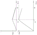
FIG. 19 shows a velocity-distance diagram for a heavy movable furniture part;
fig. 20 shows a speed-distance diagram of a lightweight movable furniture part.
Detailed Description
A piece of furniture 1 comprises a body 2, which is schematically shown in fig. 1, and on which one or more drawers can be mounted, so that the drawer can be moved as a movable furniture part 3. Each drawer 3 is guided on opposite sides via a pull-out guide 5, wherein the pull-out guide 5 is fixed on a side wall of the body 2 via a retaining angle 9 and the drawer 3 is fixed on a movable slide of the pull-out guide 5. In the closed position, the front panel 4 of the drawer is located at a slight distance from the body 2, for example between 1mm and 6mm, to be pressed from this closed position slightly deeper into the body 2 into the overpressure position in order to unlock the ejection device 6.
As shown in fig. 2, the two ejection devices 6 are coupled, at least in the closed region, to an activator 7, the activator 7 being connected to the main body 2 indirectly or directly in a fixed manner, the two ejection devices 6 being located on the bottom of the drawer on the lower side. Each ejection device 6 can therefore be supported on an activator 7 in order to eject the drawer as a movable furniture part 3. Each pull-out guide 5 is arranged in a side panel 8 of the drawer. Of course, it is also possible to arrange the ejection device 6 in a fixed manner on the main body 2 and the activator 7 on the drawer 3. Furthermore, the number and arrangement of the ejection devices 6 and the actuators 7 on the movable furniture part 3 or the main body 2 can also vary. The ejection means 6 can also be arranged on the body rail or body rail holder of the pull-out guide 5 and the activator on the drawer rail. Very different arrangement combinations of ejection devices and activators are known from the prior art, wherein the activator can also be formed directly from a movable furniture part or a non-movable part, so that the function of the activator does not require a separate component.
Each pull-out guide 5 may be coupled to a self-retractor which pulls the movable slide of the pull-out guide 5 in the closing direction in the retraction region and optionally decelerates it by means of a damper. Pull-out guide 5 with self-retractor is disclosed, for example, in the references DE 102011053840 a1 or DE 102011054441 a 1.
Fig. 3 shows the ejection device 6 arranged in the housing 10. On the longitudinal edges of the housing 10 there are provided guides 11 in the form of webs, on which the drive 12 is mounted so that it is movable. The driver 12 is connected to a coupling element 13, which coupling element 13 forms a contact surface of the activator 7. Since the coupling element 13 has magnets, both traction forces and pressure forces can be transmitted between the driver 12 and the activator 7. An adjusting mechanism 15 is provided for positioning the movable furniture part 3 in the depth direction, by means of which adjusting mechanism 15 the position of the coupling element 13 relative to the drive 12 can be set. Alternatively, the coupling element 13 can also be embodied as a controlled gripper in a guide or another mechanically detachable coupling device.
As shown in fig. 4A and 4B, a carriage 30 is located inside the housing 10, and the carriage 30 is mounted to be movable in the longitudinal direction of the housing 10 in the accommodating portion 20. The holder 21 is located on the end face on the receptacle 20 of the housing 10 for fixing the end of an energy store in the form of at least one spring, in particular a tension spring. In this case, two springs are provided, each of which is arranged in one spring receptacle 31 on the carriage 30. The opposite end of the spring is fixed to a spring holder 32 on the carriage 30, so that the carriage 30 is pretensioned on the housing 10 in the opening direction. In this case, the number of springs may be selected according to the intended use of the drive device. The housing 10 may be closed by a lid 14.
Furthermore, a receptacle 33 for guiding the control element 40 is provided on the carriage 30. A side wall 38 is arranged on the receptacle 33, the side wall 38 providing a substantially perpendicular guidance of the control element 40 to the opening direction. Furthermore, the receptacle 37 is arranged on a side wall 38 of the receptacle 33, through which a projecting web 43 of the control element 40 can be guided on the receptacle 37, in order to be able to insert the control element 40 into the receptacle 33. The control element 40 is plate-shaped and has a projecting sliding element 44, the projecting sliding element 44 being supported on the side wall 38 of the receptacle 33.
The control element 40 comprises a first pin 41, the first pin 41 being guided in a guide path 17 on the housing 10. Furthermore, a second pin 42, which is guided on the drive 12, is provided on the control element 40. For this purpose, a guide path 16 is formed on the driver 12.
Further, a curved guide 34 is provided on the carriage 30, and a gear 36 is guided by the curved guide 34. The gear 36 engages with a snap projection 35 in the curved guide 34 and is part of the backstop. A rack 19 is formed on the housing 10 as shown in the detail view of fig. 5. The gear wheel 36 is guided by a pin in an annular guide path 18 of the housing 10, wherein a part of the guide path 18 extends in the tensioning direction beyond the toothed rack 19, while a part of the guide gear wheel 36 for the opening movement is spaced apart from the toothed rack 19. If the tensioning process of the ejection device 6 is terminated, the gear wheel 36 engages in the toothed rack 19 and thus prevents the ejection of the movable furniture part. Such a non-return device is described, for example, in DE 102016107918. Such a non-return means is advantageous for the inventive push-out device, however, it can optionally also be omitted.
Furthermore, a positioning element 50 is provided on the housing 10, which positioning element 50 is held so as to be movable in a positioning element receptacle 26 (fig. 5) on the housing 10. For this purpose, the box-shaped section 55 engages in the positioning element receptacle 26, while the web 56 is received on the end section 27 of the housing 10. A bearing 52 for a rotatable switching element 60 is formed on the positioning element 50, the switching element 60 having a lever arm on which a pressure piece 62 is arranged at the end. An oval recess 61 is provided on the rotational axis of the switching element 60, in which oval recess 61 a web 66 of a rotary damper 65 engages, which rotary damper 65 is coupled to the switching element 60 in a rotationally fixed manner. The rotary damper 65 is held on the positioning element 50 via a cantilever 67, so that upon rotation of the switching element 60, the rotary damper 65 is actuated and a braking action is produced. The rotatable switch element 60 also has a protruding arm 63 which interacts with a stop on the positioning element 50 to define the rotational movement of the switch element 60.
The positioning element 50 is pretensioned in the starting position via a spring 68. In this case, the spring 68 is seated in a spring receptacle 69 on the positioning element 50 (fig. 4B), wherein the spring 68 bears on an end face on the positioning element 50 and on the opposite side on the wall of the housing 10. The spring 68 is designed as a compression spring and thus pretensions the positioning element 50 in the opening direction.
Furthermore, a yoke spring 64 is mounted on the positioning element 60, which pretensions the switching element 60 in the first position. The yoke spring 64 bears at one end on the arm 63 and is supported at the opposite end on the positioning element 50.
Furthermore, a web 53 is formed on the positioning element 50, on which web a portion 51 for the snap-in reception of the pin 41 of the control element 40 is provided. The portion 51 of the snap receiving portion is formed as a protrusion. Furthermore, snap lugs 54 are provided on the webs 53, which ensure the locking of the positioning element 50 on the housing 10.
Furthermore, in fig. 4A and 4B, a control rocker 70 is shown, which serves to actuate the switching element 60. The control rocker 70 is installed so as to be rotatable about a rotation shaft 71, and the rotation shaft 71 is inserted into a bearing receiving portion 74 on the housing 10. The control rocker 70 has a cantilever 72, the cantilever 72 acting on the switch element 60 to pivot it. Furthermore, a guide cam 73 interacting with the driver 12 is provided on the control rocker 70. When the driver 12 moves along the housing 10, the driver 12 may pivot the control rocker 70 about the rotation axis 71, thereby actuating the switching element 60. In this case, a cam guide 75 for guiding the cam 73 is formed on the driver 12 so that actuation of the switching element 60 is performed only via a defined stroke of the driver 12.
In fig. 5, the housing 10 is shown without the cover 14 and other components. A guide path 17 for the first pin 41 of the control element 40 is formed on the housing 10. In this case, the guide path 17 is formed in a ring shape. A first part 23 of the snap-in receptacle is provided on the guide path 17, at which first part 23 a pin 41 can be arranged to lock the ejection device 6. A second part 51 of the snap accommodation is formed on the positioning element 50. When the second part 51 of the snap receptacle is arranged near the first part 23 of the snap receptacle, the snap receptacle is in the closed position and the pin 41 can be seated in the snap receptacle in order to lock the ejector 6 in the closed position. If the positioning element 50 is moved relative to the housing 10, the second part 51 of the snap receptacle is moved away from the first part 23, so that the snap receptacle is moved into the unlocked or released position and the pin 41 can no longer be seated in the snap receptacle.
Furthermore, a latching projection 25 is formed on the housing 10 in the region of the guide path 17, which interacts with a latching lug 54 on the positioning element 50 in order to be able to latch the positioning element 50 in the unlocked or released position of the control element 40.
The function of the ejection device 6 will be explained in more detail below with reference to fig. 6 to 13, wherein these figures each show two sectional views through the ejection device 6, some of which are arranged in different planes, in order to be able to better follow the position of the pins 41 and 42 in the region of the driver 12 and the guide path 17.
In fig. 6A and 6B, the ejector 6 is in the closed position. In the closed position, the pin 41 of the control element 40 is located in a snap accommodation formed by the first portion 23 on the housing 10 and the second portion 51 on the positioning element 50. The catch accommodation is in the closed position and the ejector 6 is locked via the pin 41 and the catch accommodation against the force of the spring. The second pin 42 of the control element is located at an angled end of the guide path 16 at the driver 12.
If the ejection device 6 is to be unlocked, the movable furniture part 3 or drawer is moved from the closed position to the overpressure position, as shown in fig. 7A and 7B. In this case, the control element 40 is pressed in against the force of a spring held on the carriage 30, wherein the movable furniture part acts on the control element 40 via the drive 12 and the pin 42. As a result of the pressing-in of the movable furniture part 3, the first pin 41 presses against a pressure piece 62 on the switching element 60, which pressure piece 62 moves the positioning element 50 against the force of the spring 68 relative to the housing 10. Due to the movement of the positioning element 50, the second part 51 of the snap accommodation also moves relative to the first part 23.
For the opening movement, the pin 41 can now move through the gap between the first portion 23 and the second portion 51 of the snap accommodation, as shown in fig. 8A and 8B. The driver 12 is coupled to the control element 40 via a second pin 42 in the pull-out direction, so that the movable furniture part is pushed out by the driver 12. The positioning element 50 is pressed again in the opening direction by the spring 68 until the catch lug 54 bears on the catch projection 25 of the housing 10. Due to the locking of the slider 50, the catch accommodation is held in the release position. The spacing between the two portions 23 and 51 of the snap receiver is large enough so that the pin 41 can pass between them.
Due to the spring, the carriage 30 with the control element 40 and thus the drive 12 with the movable furniture part are moved further in the opening direction until the position shown in fig. 9 is reached. The first pin 41 on the control element 40 abuts against the entry ramp 57 on the web 53, thereby disengaging the catch lug 54 from the catch projection 25. Thus, the positioning element 50 can be moved further in the opening direction by the force of the spring 68 to close the snap accommodation.
The movable furniture part 3 is now moved further in the opening direction until the first pin 41 meets the entry ramp 45 of the guide path 17 in order to move the control element 40 on the carriage 30. The second pin 42 is thus moved out of the angled end section of the guide path 16 and can therefore move along an intermediate section of the guide path 16 which is aligned slightly obliquely with respect to the closing direction and the opening direction in order to move the driver 12 further along the guide 11 at the housing.
In fig. 10A and 10B, the position of the ejector device 6 is shown, in which the movable furniture part 3 can be moved away from the drive 12. In this case, the coupling between the driver 12 and the activator 7 is disengaged by overcoming the magnetic force of a magnetic coupling element 13 arranged on the driver 12. Other disengagement principles are also possible. The second pin 42 has moved at the angled end section of the guide path 16 and the first pin 41 is located at the tip of the guide path 17.
To move the movable furniture part back into the closed position, the activator 7 is moved against the drive 12, the drive 12 being coupled to the control element 40 via the second pin 42. The control element 40 thus moves together with the carriage 30 in the closing direction and simultaneously tensions the spring. In this case, the pin 41 moves on the left side of the annular guide path 17 in fig. 10 and 11. When the spring is tensioned, the non-return with the gear 36 is also activated, which moves along the rack 19 on the housing. The gear 36 of the backstop ensures that the position of the carriage 30 is tensioned to this point if the tensioning process should be terminated.
If the carriage 30 is moved further in the closing direction, on the one hand the spring is tensioned by the carriage 30 and, on the other hand, the edge of the driver 12 with the cam guide 75 moves against the guide cam 73 on the control rocker 70. When the driver 12 is pressed against the guide cam 73, the control rocker 70 pivots about the axis of rotation 71 and is pressed against the switching element 60 by the cantilever 72, the switching element 60 pivoting from a first position, in which the ejector device can be unlocked, to a second position, in which the ejector device 6 is not allowed to be unlocked. Although the pin 41 is already seated at the snap-fit accommodation, no disengagement of the ejector 6 occurs, since the switching element 60, which can establish a connection between the pin 41 and the positioning element 50, is arranged in the pivoted position. As the pin 41 moves into the snap-fit receptacle, the second pin 42 also moves out of the angled end section of the guide path 16 and can move along the driver 12. In this region, for example, between the closed position and 40mm before the closed position, the self-retractor can become active, which is arranged, for example, on the pull-out guide. Such a self-retractor pulls the movable furniture part into the closed position, wherein a damper is preferably provided which decelerates the closing movement of the movable furniture part. Thus, the user no longer needs to apply an actuation force, but may leave the control of the movable furniture part to the self-retractor. If the drive 12 is moved slowly via the self-retractor into the closed position, the cam guide 75 moves in a groove into the region of the guide cam 73, so that the control rocker 70 can be pivoted by the force of the yoke spring 64, since the switching element 60 is pivoted back by the force of the yoke spring 64 into the first position in which the ejection device 6 can be unlocked. The second pin 42 is then located at the angled end of the guide path 16 and reaches the closed position shown in fig. 6A and 6B. In this type of closing process, the drawer is not pressed beyond the closed position into the overpressure position, and the user can again effect unlocking of the ejection device 6 immediately after the closed position is reached, since unlocking can take place via pivoting of the switching element 60 into the first position when the closed position is reached.
However, due to an excessively high closing speed of the movable furniture part 3, it may happen that the movable furniture part can be moved manually beyond the closing position into the overpressure position or beyond the closing position. And then to the overpressure position shown in fig. 13A and 13B. In the overpressure position, the control rocker 70 pivots the switching element 60 from the first position to the second position, as shown in fig. 13A and 13B, due to the cam guide 75 and the guide cam 73 on the driver 12. The snap accommodation is in the closed position, but the pin 41 is arranged spaced apart from the snap accommodation. However, the pin 41 does not bear on the end face of the pressure piece 62, but rather bears laterally on the pressure piece 62, so that the pin 41 does not exert a force on the switching element 60 in the closing direction. If the movable furniture part is released in the overpressure position, the spring ensures that the driver 12 and the control element 40 move in the opening direction relative to the housing 10 until the first pin 41 rests on the catch receptacle formed by the first portion 23 on the housing 10 and the second portion 51 on the positioning element 50 and the position shown in fig. 6A and 6B is reached. When the pin 41 is seated at the catch reception, the movement of the driver 12 along the housing 10 takes place simultaneously, so that the guide cam 73 is released by the cam guide 75 sufficiently for the switching element 60 to be pivotable from the second position into the first position by the force of the yoke spring 64. After the closed position is reached, the opening procedure can be carried out again. If it is desired to perform another opening only after a certain duration, the swivelling movement of the switching element 60 can be slowed down by means of the rotary damper 65, depending on the duration to be waited for. However, such a time delay is only optional, since the movable furniture part can also be opened immediately after the overpressure has been applied to the movable furniture part to the overpressure position once the movable furniture part has reached the closed position. For delayed swivel or push back movements, a linear damper or another mechanical timing element may also be provided. Simple mechanical timing elements are for example suction cups with small holes, which are out of contact with the surface due to the inflowing air; or an elastomer with a slow recovery movement. If an elastomer is used, the spring 64 can be omitted for the restoring movement, since the elastomer itself can have an elastic action.
A distance-time diagram is shown in fig. 14, which illustrates the closing process, during which the overpressure position is not reached. The movable furniture part 3 is moved in the closing direction and the energy store is simultaneously tensioned in the first section on the carriage 30. After the force accumulator with spring is tensioned and the ejector 6 is locked on the snap-in receiver via the pin 41, the self-retractor can receive and decelerate the movement of the movable furniture part 3 in the closing direction, as indicated by the curved contour in the constriction region. The movable furniture part 3 then reaches the closed position and no further movement takes place until the user moves the movable furniture part 3 into the overpressure position and thus unlocks the ejection device 6.
Fig. 15 shows that the closing process can also take place in an overpressure position, in which the movable furniture part 3 is moved in the closing direction in the tensioning region and additionally also in the retraction region, in particular beyond the closing position into the overpressure position. In the overpressure position, the movable furniture component may be held as desired until it is released by the user and then moved to the closed position. As soon as the movable furniture part 3 is arranged in the closed position, it can be opened again.
In the exemplary embodiment shown, the switching element 60 is mounted such that it can rotate. A movably mounted switching element 60 may also be provided in the mechanism for an overpressure protection device.
In fig. 16, the push-out device 6 is shown in a position during the opening movement, in which the driver 12 has moved a part of the travel distance on the housing 10 in the opening direction, and the carriage 30 is arranged shortly before reaching its end position on the housing 10. The first pin 41 has just moved against the entry ramp 45 on the guide path 17, so that the control element 40 is not only moved with the carriage 30 in the opening direction, but also slightly to the right in fig. 16, so that the second pin 42 is moved out of the angled end section of the guide path 16, and thus the coupling between the control element 40 and the driver 12 is unlocked.
If the drive 12 is now moved further in the opening direction, as shown in fig. 17, the second pin 42 moves relative to the guide path 16 and along the guide path 16, the guide path 16 being aligned slightly obliquely relative to the opening direction and the closing direction, for example at an angle of between 1 ° and 20 °, in particular 5 ° to 15 °, so that the control element 40 also moves to the right during the further opening movement in fig. 17. In this case, a friction force acts through the control element 40 and the pins 41 and 42, which friction force slightly decelerates the movement of the driver 12. The carriage 30 is only slightly displaced in the opening direction in this region, but may also be arranged fixedly. The driver 12 moves further in the opening direction together with the movable furniture part 3.
In fig. 18, the second pin 42 has reached the second angled end of the guide path 16, so that the detachment of the movable furniture part 3 from the driver 12 can now take place, similarly as described with reference to fig. 10. Alternatively, the driver 12 may also move further along the housing 10 in the opening direction until stopped. During the subsequent closing movement, the pin 42 is then held at the angled end section of the guide path 16 at the top in fig. 18, in order to move the driver 12 together with the carriage 30 in the closing direction and to tension the spring.
A speed-distance diagram of a heavy movable furniture part 3 is shown in fig. 19. The movable furniture part 3 is moved from the closed position into the overpressure position, so that the ejection device 6 can eject the movable furniture part. The movable furniture part 3 is accelerated by the ejection device 6 from the overpressure position by a first travel distance up to a point S1. In fig. 19, the movable furniture part is heavy and therefore the resulting acceleration is small. After reaching the position shown in fig. 16, no further acceleration takes place on the movable furniture part due to the accumulator of the ejection device, but rather a slight deceleration due to the frictional forces during the movement of the movable furniture part and the drive 12 in the opening direction, until reaching the position shown in fig. 18, which corresponds to point S in fig. 192. Along S1And S2The dashed line of the second travel distance in between shows the difference of this situation when no braking force acts on the movable furniture part 3 via the actuator 12. Movable furniture part over a travel distance S2At the end, it is only slightly faster, wherein deceleration can also occur due to further frictional forces on the pull-out guide 5 or on other components acting on the movable furniture part 3.
Fig. 20 shows a speed-distance diagram of a lightweight movable furniture part 3, in which the same ejection device 6 with the same spring is used. The movable furniture part 3 is first in the opening directionAccelerating from an overpressure position, or from a closed position by optional unlocking, until a speed V of a first travel distance is reachedmaxAnd reaches the position shown in fig. 16. After reaching the first travel distance, a certain braking action is produced on the drive 12 via the friction force via the ejection device, wherein the second travel distance (S)2) The final speed difference at the end is greater than that in fig. 19. Because the movable furniture part 3 is lighter. The unbraked movable furniture part 3 is shown by the dashed line in fig. 20, whereas S1And S2The solid line in between represents the braking action of the actuator 12. In particular for lightweight furniture parts, the deceleration of the movable furniture part 3 prevents it from being pushed out in the opening direction at too high a speed, so that a forced stop in the maximum opening position can be prevented.
In order to reach the maximum speed V at the beginning of the second driving distancemaxAfter which the speed is decelerated, alternatively or additionally, further dampers may also be provided, for example air dampers, fluid dampers, linear dampers or rotary dampers. The damping force is preferably speed-dependent, i.e. the higher the speed of the movable furniture part at the end of the first travel distance, the greater the damping force which decelerates the ejection speed more strongly at higher speeds. The damper is preferably designed such that it produces damping during the opening movement, while the damper produces little damping during the closing movement.
As can be seen in fig. 16 to 18, during the movement of the driver 12 in the opening direction, the carriage 30 is also moved to a minimum extent in the opening direction. This results in the spring energy of the spring being dissipated during movement in the region of the second travel distance during movement of the driver 12. Due to the inclination of the guide path 16, the force component acting on the driver 12 due to the pin 42 changes counter to the direction of movement of the driver 12.
Instead of the second angled end section, the guide path 16 may also have a gradual cross-sectional constriction, wherein preferably the pin 42 is held clamped in the guide path 16 in the end region. Alternatively or additionally, the guide path may have a coating with plastic, preferably with an elastomer, to achieve a stronger deceleration and soft contact of the pin 42 at the end region of the guide path 16.
List of reference numerals
1 furniture
2 main body
3 furniture parts
4 front panel
5 Pull-out guide
6 push-out device
7 activating device
8 side panel
9 holding angle
10 casing
11 guide piece
12 driver
13 coupling element
14 cover
15 adjustment mechanism
16 guide path
17 guide path
18 guide path
19 rack
20 accommodating part
21 holder
22 accumulator
25 snap-fit projection
26 positioning element receiving part
27 end section
30 carriage
31 spring housing
32 spring retainer
33 accommodating part
34 bending guide
35 snap-fit projection
36 gear
37 accommodating part
38 side wall
40 control element
41 pin
42 pin
43 web
44 sliding element
45 into the inclined plane
50 positioning element
52 bearing
53 Web
54 snap lug
56 Web plate
57 into the incline
60 switching element
61 recess
62 pressure piece
63 arm
64 yoke spring
65 rotary damper
66 Web plate
67 cantilever
68 spring
69 spring housing
70 control rocker
71 rotating shaft
72 cantilever
73 guide cam
74 bearing receiving part
75 cam guide
S1Dot
Point S2
VMAXSpeed.
Claims (16)
1. A drive device for a movable furniture part (3), with an ejection device (6), which ejection device (6) has a carriage (30), which carriage (30) is pretensioned by an accumulator (22) and can be coupled to the movable furniture part (3) via a driver (12), wherein, upon unlocking of the ejection device (6), the movable furniture part (3) is accelerated in the opening direction via the carriage (30) and the driver (12) from an overpressure or closed position by a first travel distance, and after the first travel distance, the movable furniture part (3) can be moved by a second travel distance at which the driver (12) can be moved relative to the carriage (30), characterized in that, during the second travel distance, a braking force acts on the driver (12) and the movable furniture part (3), and the drive (12) can be separated from the movable furniture part (3) at the end of the second travel distance, a damping or braking device being provided which acts only after the first travel distance.
2. The drive of claim 1, wherein the braking force is generated by sliding friction.
3. The drive device according to claim 1 or 2, characterized in that the ejection device (6) has a housing (10) on which the carriage (30) and the drive (12) are guided.
4. The drive device according to claim 3, characterized in that the carriage (30) is coupled to the driver (12) via a control element (40), the control element (40) being mounted such that it can move on the carriage (30).
5. The drive device according to claim 4, characterized in that the control element (40) has a first pin (41) and a second pin (42), the first pin (41) being guided in a guide path (17) on the housing (10), the second pin (42) engaging in a path (16) on the driver (12).
6. The drive according to claim 1 or 2, characterized in that the braking force is speed dependent and that at higher speeds of the movable furniture part (3) a higher braking force is generated than at lower speeds of the movable furniture part (3).
7. The drive device according to claim 1 or 2, characterized in that a retraction device is provided, by means of which the movable furniture part (3) can be moved along a retraction area into the closed position.
8. The drive according to claim 1 or 2, characterized in that the energy store (22) can be tensioned during the closing movement of the movable furniture part (3), wherein a tensioning region is offset relative to a relaxation region of the energy store (22) as viewed in the opening or closing direction and terminates spaced apart from the closed position of the movable furniture part.
9. The drive device according to claim 4, characterized in that the control element (40) is arranged on the carriage (30) such that the control element (40) is guided on the carriage (30) substantially perpendicular to the direction of movement of the carriage (30).
10. The drive device according to claim 5, characterized in that a path (16) for the second pin (42) of the control element (40) is formed on the driver (12), wherein the path (16) has two angled end sections and one intermediate section, which is aligned at least partially obliquely with respect to the opening and closing direction.
11. The drive arrangement according to claim 10, characterized in that the second pin (42) transmits a force component in the direction of movement of the driver (12) in the region of the first travel distance and transmits a force component opposite to the direction of movement of the driver (12) to the driver (12) in the region of the second travel distance.
12. The drive of claim 1, wherein the braking force is generated by a damper.
13. Method for opening a movable furniture part (3) having an ejection device (6), having the following steps:
-unlocking the ejector device (6);
-accelerating the movable furniture part (3) along a first travel distance from an overpressure or closed position to a first open position by means of an accumulator (22);
-decelerating the movable furniture part (3) along a second travel distance from the first open position to a second open position located further in the opening direction by a damping or braking device acting only after the first travel distance;
-disconnecting the movable furniture part (3) from the drive (12) of the ejector device (6) and leaving the movable furniture part (3) free to move in the opening direction.
14. Method according to claim 13, characterized in that at least a part of the braking force is generated by sliding friction which is active as a result of the movement of the control element (40) relative to the drive (12) during the movement of the movable furniture part (3) along the second travel distance.
15. A method according to claim 13 or 14, characterized in that at least a part of the braking force is generated by a damper.
16. The method of claim 14, wherein at least a portion of the braking force is generated by friction braking.
Applications Claiming Priority (5)
| Application Number | Priority Date | Filing Date | Title |
|---|---|---|---|
| DE102016113045 | 2016-07-15 | ||
| DE102016113045.1 | 2016-07-15 | ||
| DE102016123481.8 | 2016-12-05 | ||
| DE102016123481.8A DE102016123481A1 (en) | 2016-07-15 | 2016-12-05 | Drive device for a movable furniture part and method for opening a movable furniture part |
| PCT/EP2017/067788 WO2018011379A1 (en) | 2016-07-15 | 2017-07-13 | Drive device for a moveable furniture part, and method for opening a moveable furniture part |
Publications (2)
| Publication Number | Publication Date |
|---|---|
| CN109475230A CN109475230A (en) | 2019-03-15 |
| CN109475230B true CN109475230B (en) | 2021-08-10 |
Family
ID=60782523
Family Applications (2)
| Application Number | Title | Priority Date | Filing Date |
|---|---|---|---|
| CN201780043272.1A Active CN109475231B (en) | 2016-07-15 | 2017-07-13 | Drive device for a movable furniture part and method for closing a movable furniture part |
| CN201780043221.9A Active CN109475230B (en) | 2016-07-15 | 2017-07-13 | Drive device for a movable furniture part and method for opening a movable furniture part |
Family Applications Before (1)
| Application Number | Title | Priority Date | Filing Date |
|---|---|---|---|
| CN201780043272.1A Active CN109475231B (en) | 2016-07-15 | 2017-07-13 | Drive device for a movable furniture part and method for closing a movable furniture part |
Country Status (5)
| Country | Link |
|---|---|
| EP (2) | EP3484325B1 (en) |
| CN (2) | CN109475231B (en) |
| DE (2) | DE102016123481A1 (en) |
| ES (2) | ES2829297T3 (en) |
| WO (2) | WO2018011380A1 (en) |
Families Citing this family (3)
| Publication number | Priority date | Publication date | Assignee | Title |
|---|---|---|---|---|
| DE102017108453A1 (en) | 2017-04-20 | 2018-10-25 | Paul Hettich Gmbh & Co. Kg | Furniture |
| DE102018123221A1 (en) * | 2018-09-20 | 2020-03-26 | Paul Hettich Gmbh & Co. Kg | Drive device for a drawer and furniture or household appliance |
| DE102019107690A1 (en) * | 2019-03-26 | 2020-10-01 | Paul Hettich Gmbh & Co. Kg | Feeding or ejecting device |
Citations (6)
| Publication number | Priority date | Publication date | Assignee | Title |
|---|---|---|---|---|
| CN1296391A (en) * | 1999-03-12 | 2001-05-23 | 艾库里德国际有限公司 | Slide detent device |
| WO2009132626A1 (en) * | 2008-04-29 | 2009-11-05 | Zimmer Guenther | Acceleration apparatus with two energy stores |
| DE102010036902A1 (en) * | 2009-08-07 | 2011-02-10 | Paul Hettich Gmbh & Co. Kg | Ejection mechanism, pullout guide and ejection system |
| CN102821653A (en) * | 2010-04-01 | 2012-12-12 | 保罗海蒂诗有限及两合公司 | Push-out apparatus |
| CN104042046A (en) * | 2013-03-15 | 2014-09-17 | 川湖科技股份有限公司 | Deceleration structure for stretching and positioning sliding rail |
| CN104125788A (en) * | 2011-12-23 | 2014-10-29 | 格拉斯有限公司 | Device for influencing the movement of a furniture part, guide unit for guiding the movement of a furniture part, and item of furniture |
Family Cites Families (17)
| Publication number | Priority date | Publication date | Assignee | Title |
|---|---|---|---|---|
| DE19935120C2 (en) * | 1999-07-27 | 2001-05-17 | Bulthaup Gmbh & Co | Device for opening and closing a drawer |
| AT503139B1 (en) * | 2006-02-08 | 2009-02-15 | Blum Gmbh Julius | OUTBOARD WITH SLIP COUPLING |
| AT503497B1 (en) * | 2006-04-05 | 2012-05-15 | Blum Gmbh Julius | DRIVE MECHANISM FOR A FURNITURE STORED IN OR ON A FURNITURE |
| WO2008041544A1 (en) * | 2006-09-27 | 2008-04-10 | Thk Co., Ltd. | Assisted drawer device |
| EP2299872A4 (en) * | 2008-07-24 | 2012-04-25 | Grass America Inc | Control mechanism for drawer slide assembly |
| DE202009014685U1 (en) | 2009-10-14 | 2010-06-17 | Karl Simon Gmbh & Co. Kg | sliding arrangement |
| DE202010009794U1 (en) * | 2010-07-02 | 2011-11-08 | Grass Gmbh | Device with a power storage and a movably mounted opening element and furniture |
| DE202010013193U1 (en) * | 2010-12-22 | 2012-03-26 | Paul Hettich Gmbh & Co. Kg | Opening and closing device for movable furniture parts and ejection device |
| CN102106658B (en) * | 2011-02-22 | 2014-06-18 | 伍志勇 | Drawer slide rail part |
| CN102275706B (en) * | 2011-05-10 | 2013-01-02 | 江苏迅捷装具科技有限公司 | Horizontal-moving movable frame delivery device |
| DE102011053840B4 (en) | 2011-09-21 | 2021-03-25 | Paul Hettich Gmbh & Co. Kg | Pull-in device for installation in a pull-out guide |
| DE102011054441A1 (en) | 2011-10-12 | 2013-04-18 | Paul Hettich Gmbh & Co. Kg | Opening and closing device for drawer element, has running rail movable from close position in opening direction after releasing ejector, where force accumulator of ejector is chargeable by force accumulator of self-closing mechanism |
| AT511964B1 (en) * | 2011-12-27 | 2013-04-15 | Blum Gmbh Julius | DRIVE DEVICE FOR A MOVABLE FURNITURE PART |
| DE202013011558U1 (en) | 2013-12-23 | 2015-03-24 | Grass Gmbh | Device for opening a movable furniture part |
| WO2016090406A1 (en) * | 2014-12-10 | 2016-06-16 | Shane Miles | Drawers and components for drawers |
| CN104997305B (en) * | 2015-08-12 | 2018-02-13 | 伍志勇 | The powered bounce-back structure of drawer sliding rail |
| DE102016107918A1 (en) | 2016-04-28 | 2017-11-02 | Paul Hettich Gmbh & Co. Kg | Ejector for a movable furniture part and furniture |
-
2016
- 2016-12-05 DE DE102016123481.8A patent/DE102016123481A1/en active Pending
- 2016-12-05 DE DE102016123482.6A patent/DE102016123482A1/en not_active Withdrawn
-
2017
- 2017-07-13 ES ES17745663T patent/ES2829297T3/en active Active
- 2017-07-13 WO PCT/EP2017/067789 patent/WO2018011380A1/en unknown
- 2017-07-13 EP EP17745663.9A patent/EP3484325B1/en active Active
- 2017-07-13 CN CN201780043272.1A patent/CN109475231B/en active Active
- 2017-07-13 CN CN201780043221.9A patent/CN109475230B/en active Active
- 2017-07-13 ES ES17748655T patent/ES2829348T3/en active Active
- 2017-07-13 WO PCT/EP2017/067788 patent/WO2018011379A1/en unknown
- 2017-07-13 EP EP17748655.2A patent/EP3484326B1/en active Active
Patent Citations (7)
| Publication number | Priority date | Publication date | Assignee | Title |
|---|---|---|---|---|
| CN1296391A (en) * | 1999-03-12 | 2001-05-23 | 艾库里德国际有限公司 | Slide detent device |
| WO2009132626A1 (en) * | 2008-04-29 | 2009-11-05 | Zimmer Guenther | Acceleration apparatus with two energy stores |
| DE102010036902A1 (en) * | 2009-08-07 | 2011-02-10 | Paul Hettich Gmbh & Co. Kg | Ejection mechanism, pullout guide and ejection system |
| CN102469880A (en) * | 2009-08-07 | 2012-05-23 | 保罗海蒂诗有限及两合公司 | Ejection mechanism, pull-out guide and ejection system |
| CN102821653A (en) * | 2010-04-01 | 2012-12-12 | 保罗海蒂诗有限及两合公司 | Push-out apparatus |
| CN104125788A (en) * | 2011-12-23 | 2014-10-29 | 格拉斯有限公司 | Device for influencing the movement of a furniture part, guide unit for guiding the movement of a furniture part, and item of furniture |
| CN104042046A (en) * | 2013-03-15 | 2014-09-17 | 川湖科技股份有限公司 | Deceleration structure for stretching and positioning sliding rail |
Also Published As
| Publication number | Publication date |
|---|---|
| EP3484325B1 (en) | 2020-09-02 |
| EP3484326A1 (en) | 2019-05-22 |
| ES2829297T3 (en) | 2021-05-31 |
| ES2829348T3 (en) | 2021-05-31 |
| WO2018011379A1 (en) | 2018-01-18 |
| CN109475230A (en) | 2019-03-15 |
| CN109475231A (en) | 2019-03-15 |
| DE102016123482A1 (en) | 2018-01-18 |
| CN109475231B (en) | 2021-03-23 |
| WO2018011380A1 (en) | 2018-01-18 |
| EP3484326B1 (en) | 2020-09-02 |
| DE102016123481A1 (en) | 2018-01-18 |
| EP3484325A1 (en) | 2019-05-22 |
Similar Documents
| Publication | Publication Date | Title |
|---|---|---|
| CN109475234B (en) | Drive device for a movable furniture part and method for opening and closing a movable furniture part | |
| CN109475230B (en) | Drive device for a movable furniture part and method for opening a movable furniture part | |
| CN109072653B (en) | Ejection device for movable furniture part and furniture | |
| US11002044B2 (en) | System composed of a door handle and of an actuation device for the door handle | |
| KR101860622B1 (en) | Drive device for a movable furniture part | |
| US9655447B2 (en) | Drive device for a movable furniture part | |
| RU2635913C2 (en) | Accelerating device for mobile parts of furniture or household appliance | |
| CN109475232B (en) | Drive device for a movable furniture part and piece of furniture | |
| US8109582B2 (en) | Lockable pushing-out device | |
| US8511763B2 (en) | Self-closing device for a drawer or for a moveable part of a piece of furniture | |
| CN110249103B (en) | Locking device and sliding door with locking device | |
| CN109862808B (en) | Drive device for a movable furniture part | |
| JP2015521924A (en) | Driving device for moving parts of furniture | |
| JP2015507508A (en) | Drive unit for movable furniture | |
| AU2011281655A1 (en) | Ejector unit and push device | |
| CN110344680A (en) | Grip structure outside a kind of automatic backswing for vehicle | |
| CN111246777B (en) | Drive device for a movable furniture part, arrangement and piece of furniture | |
| CN109475229B (en) | Drive device for a movable furniture part and method for opening and closing a movable furniture part | |
| CN109068851B (en) | Ejection device for a movable furniture part and piece of furniture | |
| CN109152480B (en) | Ejection device for a movable furniture part, furniture part and method for opening and closing a movable furniture part | |
| CN111148453B (en) | Drive device for a movable furniture part | |
| RU2646192C2 (en) | Guide device | |
| CN109922694B (en) | Furniture and method for opening drawers and inner drawers | |
| CN111031857B (en) | Retraction device for retracting a movable part of a piece of furniture or a household appliance into an end position | |
| CN112512375A (en) | Pull-out unit and method for moving a pull-out guide having a drawer element |
Legal Events
| Date | Code | Title | Description |
|---|---|---|---|
| PB01 | Publication | ||
| PB01 | Publication | ||
| SE01 | Entry into force of request for substantive examination | ||
| SE01 | Entry into force of request for substantive examination | ||
| GR01 | Patent grant | ||
| GR01 | Patent grant |