CN108927646B - Coil body feeding device and automatic inductance element assembling equipment - Google Patents
Coil body feeding device and automatic inductance element assembling equipment Download PDFInfo
- Publication number
- CN108927646B CN108927646B CN201810953788.6A CN201810953788A CN108927646B CN 108927646 B CN108927646 B CN 108927646B CN 201810953788 A CN201810953788 A CN 201810953788A CN 108927646 B CN108927646 B CN 108927646B
- Authority
- CN
- China
- Prior art keywords
- coil body
- seat
- block
- rack
- cylinder
- Prior art date
- Legal status (The legal status is an assumption and is not a legal conclusion. Google has not performed a legal analysis and makes no representation as to the accuracy of the status listed.)
- Active
Links
Images


Classifications
-
- B—PERFORMING OPERATIONS; TRANSPORTING
- B23—MACHINE TOOLS; METAL-WORKING NOT OTHERWISE PROVIDED FOR
- B23P—METAL-WORKING NOT OTHERWISE PROVIDED FOR; COMBINED OPERATIONS; UNIVERSAL MACHINE TOOLS
- B23P19/00—Machines for simply fitting together or separating metal parts or objects, or metal and non-metal parts, whether or not involving some deformation; Tools or devices therefor so far as not provided for in other classes
- B23P19/001—Article feeders for assembling machines
- B23P19/002—Article feeders for assembling machines orientating the articles
-
- B—PERFORMING OPERATIONS; TRANSPORTING
- B23—MACHINE TOOLS; METAL-WORKING NOT OTHERWISE PROVIDED FOR
- B23P—METAL-WORKING NOT OTHERWISE PROVIDED FOR; COMBINED OPERATIONS; UNIVERSAL MACHINE TOOLS
- B23P19/00—Machines for simply fitting together or separating metal parts or objects, or metal and non-metal parts, whether or not involving some deformation; Tools or devices therefor so far as not provided for in other classes
- B23P19/001—Article feeders for assembling machines
- B23P19/007—Picking-up and placing mechanisms
-
- B—PERFORMING OPERATIONS; TRANSPORTING
- B23—MACHINE TOOLS; METAL-WORKING NOT OTHERWISE PROVIDED FOR
- B23P—METAL-WORKING NOT OTHERWISE PROVIDED FOR; COMBINED OPERATIONS; UNIVERSAL MACHINE TOOLS
- B23P21/00—Machines for assembling a multiplicity of different parts to compose units, with or without preceding or subsequent working of such parts, e.g. with programme control
Abstract
The invention relates to the field of production of inductive components. Coil body loading attachment is including charging tray frame, charging tray, locking bar, second motor, coil body punishment in advance track, conveyor belt and coil body tilting mechanism. The coil body feeding device has the advantages that the working efficiency of the machine is improved, and the blocking condition in the feeding process is reduced.
Description
Technical Field
The invention relates to the field of production of inductance elements, in particular to full-automatic assembly equipment of the inductance elements.
Background
The inductance element is an energy storage element which is made by winding a magnetic iron core by a lead, and is mainly formed by assembling an elastic sheet, a coil body and the iron core. The elastic sheet is L-shaped, so that the natural state is difficult to erect, and the automatic feeding ratio of the elastic sheet is difficult in the process of assembling the inductance element; the coil body is small in size, difficult to feed in a vertical state and easy to block in the feeding process; the existing elastic piece feeding device has the problems of low automatic feeding efficiency and low processing yield, and the existing inductance element assembling equipment has the problem of low full-automatic assembling efficiency.
Disclosure of Invention
One purpose of the invention is to provide a coil body feeding device which is convenient to automatically feed and high in processing efficiency; the invention aims to provide automatic assembly equipment for an inductance element, which is used for automatically assembling an elastic sheet, a coil body and an iron core.
In order to achieve the purpose, the invention adopts the following technical scheme: the coil body feeding device comprises a coil plate frame, a material plate, a locking bar, a second motor, a coil body material passing rail, a conveying belt and a coil body overturning mechanism; the charging tray frame is arranged on the rack, a charging tray is placed in the charging tray frame, and one end of the locking bar is rotatably connected to the charging tray frame; the second motor and the conveying belt are both arranged on the coil body feeding track, and the second motor drives the conveying belt to move so as to carry the coil body on the conveying belt; the coil body overturning mechanism is positioned at the discharge end of the coil body feeding track and used for overturning the coil body; the coil body overturning mechanism comprises an overturning seat, a rotating groove seat, a rotating block, a lifting slide rail, a rack, a gear and a seventh cylinder; the turning seat is arranged on the frame, and the rotating groove seat is arranged on the turning seat; the transfer block is provided with a coil slot which is matched with the shape of the coil body and used for placing the coil body; the rotating block is rotationally connected to the rotating groove seat through a pin shaft; the gear is arranged on the pin shaft, the rack is arranged on the lifting slide rail, and the rack is meshed with the gear; the lifting slide rail is vertically movably matched on the turnover seat, the seventh cylinder is fixedly arranged on the turnover seat, the telescopic end of the seventh cylinder is connected with the lifting slide rail, and the seventh cylinder drives the lifting slide rail to move up and down.
The automatic assembly equipment for the inductance element comprises a rack, and an elastic piece feeding device, a first carrying manipulator device, a jig conveying device, a second carrying manipulator device, a third carrying manipulator device, an iron core feeding device, an iron core loading device, a press riveting device and the coil body feeding device which are arranged on the rack; the first carrying manipulator device is used for carrying the elastic sheets in the elastic sheet feeding device to the jig conveying device; the second carrying manipulator device is used for carrying the workpieces on the coil body feeding device; the third carrying manipulator device carries the coil body on the coil body feeding device into the jig conveying device; the iron core feeding device conveys the iron core to the iron core device; the coil body material passing rail is installed on the rack.
Preferably, the second carrying manipulator device comprises a carrying bracket, a third motor, an eighth cylinder, a ninth cylinder, a rotary clamping piece, a clamping piece rotating seat, a movable clamping head mounting seat, a movable clamping head, a fixed clamping head and a transverse extending arm; the carrying bracket is fixedly arranged on the frame; the transverse arm is connected to the carrying support, the third motor controls the transverse arm to move horizontally, and the eighth cylinder controls the transverse arm to move vertically; the ninth cylinder is arranged on the transverse extending arm, the telescopic end of the ninth cylinder and a connecting groove piece at the upper end of the rotating clamping piece form a moving groove pair connection, the rotating clamping piece is made of a magnet, the straight section at the lower end of the rotating clamping piece and the clamping piece rotating seat form a rotating connection, and the clamping piece rotating seat is arranged on the transverse extending arm; the movable chuck mounting seat is arranged on the transverse arm, and the middle of the movable chuck is rotationally connected to the movable chuck mounting seat; the movable chuck is made of iron material which is easy to attract by a magnet; the movable chucks are arranged side by side, the width of each movable chuck is matched with the height of the coil body, and wedge grooves matched with the coil body are formed in the lower ends of the movable chucks; the fixed chuck is arranged on the transverse extending arm, and the lower end of the fixed chuck is provided with a second wedge groove corresponding to the movable chuck in position.
Preferably, the elastic piece feeding device comprises an elastic piece overturning mechanism, a vibration material passing mechanism and an elastic piece sorting mechanism; the elastic piece turnover mechanism, the vibration material passing mechanism and the elastic piece sorting mechanism are sequentially connected and arranged along the elastic piece feeding direction; the elastic piece overturning mechanism overturns the horizontally placed elastic piece into a vertical elastic piece; the elastic sheet turnover mechanism comprises a material changing seat, a rotating block, a first air cylinder, a second air cylinder and a material pushing block; the rotating block is connected with the material changing seat through a pin shaft and is positioned in the middle of the material changing seat; the lower end of the rotating block is rotationally connected with the telescopic end of the first cylinder; the rotating block is provided with a spring plate groove matched with the outer contour of the spring plate; the second cylinder is arranged on the material changing seat through a second cylinder mounting block, the material pushing block is arranged on the telescopic end of the second cylinder, the material pushing end of the material pushing block is positioned in the material changing seat, and the material pushing end of the material pushing block is matched with the elastic sheet groove of the rotating block; the vibrating and feeding mechanism comprises a first vibrating motor fixing seat, a first vibrating motor and a feeding rail; the material passing rail is arranged at the upper end of the first vibrating motor, and an L-shaped groove matched with the shape of the elastic sheet is arranged in the material passing rail; the elastic piece sorting mechanism comprises an elastic piece sorting base, a third air cylinder, a sorting block, a first linear sliding rail assembly and a first optical fiber sensor; the sorting block is provided with a sorting groove matched with the elastic sheet, the sorting block is movably connected to the elastic sheet sorting base through a first linear sliding rail assembly, and the thickness of the sorting block is matched with the width of the elastic sheet; the third cylinder is arranged on the sorting base, and the telescopic end of the third cylinder is connected with the sorting block; the first optical fiber sensor is arranged on the elastic piece sorting base, and the optical fiber head just divides the sorting block; the material changing seat and the elastic piece sorting base are arranged on the rack; the first air cylinder is connected to the rack through a first air cylinder mounting block; first vibrating motor passes through first vibrating motor fixing base setting in the frame.
By adopting the coil body feeding device in the technical scheme, the problem of low feeding efficiency of small devices is solved by adopting charging of the charging tray, and the problem of difficult feeding of the coil body in a vertical state is solved by adopting the coil body overturning mechanism; the coil body feeding device has the advantages that the working efficiency of the machine is improved, and the blocking condition in the feeding process is reduced. The automatic assembly equipment for the inductance element solves the problem that the elastic sheet and the coil body are difficult to automatically feed, improves the processing efficiency, and has the advantages that the assembly of the elastic sheet, the coil body and the iron core is automatically and efficiently completed.
Drawings
Fig. 1 is a schematic structural diagram of an embodiment of the present invention.
Fig. 2 is an exploded view of the spring loading device according to the embodiment of the present invention.
Fig. 3 is a schematic view of an explosion structure of the spring plate turnover mechanism according to the embodiment of the invention.
Fig. 4 is an exploded view of the vibrating material feeding mechanism according to the embodiment of the present invention.
Fig. 5 is a schematic structural diagram of the spring plate sorting mechanism according to the embodiment of the present invention.
Fig. 6 is a schematic structural diagram of a first transfer robot apparatus according to an embodiment of the present invention.
Fig. 7 is an exploded view of a tool conveying device according to an embodiment of the invention.
Fig. 8 is a schematic diagram of an explosive structure of a treatment apparatus according to an embodiment of the present invention.
Fig. 9 is an exploded view of a coil body feeding device according to an embodiment of the present invention.
Fig. 10 is an exploded view of a coil body turnover mechanism according to an embodiment of the present invention.
Fig. 11 is an exploded view of the second transfer robot apparatus according to the embodiment of the present invention.
Fig. 12 is an exploded view of a third transfer robot apparatus according to an embodiment of the present invention.
Fig. 13 is an exploded view of the core loading apparatus according to the embodiment of the present invention.
Fig. 14 is an exploded view of the core assembly according to the embodiment of the present invention.
Fig. 15 is an exploded view of the clincher device according to the embodiment of the present invention.
Fig. 16 is an exploded view of the fourth transfer robot mechanism according to the embodiment of the present invention.
Fig. 17 is an exploded view of a positioning mechanism according to an embodiment of the present invention.
Fig. 18 is an exploded view of a riveting assembly according to an embodiment of the invention.
Fig. 19 is an exploded view of a product discharge device according to an embodiment of the present invention.
Detailed Description
The invention is further described below in connection with fig. 1-19.
The automatic assembling equipment for inductance components shown in fig. 1-19 comprises a frame 14, and an elastic sheet feeding device 1, a first carrying manipulator device 2, a jig conveying device 3, a coil body feeding device 4, a second carrying manipulator device 5, a third carrying manipulator device 6, an iron core feeding device 7, an iron core loading device 8, a pressure riveting device 9 and a finished product discharging device 10 arranged on the frame.
The inductor is mainly assembled by a spring sheet a, a coil body b and an iron core d, and the spring sheet a, the coil body b and the iron core d are sequentially loaded.
The elastic piece feeding device 1 is used for feeding elastic pieces, the elastic piece feeding device 1 is connected with the jig conveying device 3 through the first carrying manipulator device 2, and the first carrying manipulator device 2 is used for carrying the elastic pieces in the elastic piece feeding device 1 to the jig conveying device 3; the jig conveying device 3 is used for circularly driving the jigs to rotate, so that the workpieces in the jigs move to corresponding stations to carry out corresponding operation; the coil body feeding device 4 is positioned on the side of the jig conveying device 3 and used for feeding the coil body, and the coil body is placed in the material tray; the second conveying manipulator device 5 is used for conveying the workpieces on the coil body feeding device 4; the third carrying manipulator device 6 carries the coil body from the coil body feeding device 4 to the jig conveying device 3; the iron core feeding device 7 is arranged on the other side of the jig conveying device 3 and used for feeding the iron core and conveying the iron core into the iron core loading device 8; the iron core loading device 8 is positioned right above the jig conveying device 3 and is used for loading the iron core into the coil body in the jig; the press riveting device 9 is positioned at the end part of the advancing direction of the jig conveying device 3 and is used for press riveting connection of the fully assembled inductors to form a whole; the finished product discharging device 10 is connected with the pressure riveting device 9 and used for conveying the processed finished products out of the working machine.
As shown in fig. 2-6, the elastic piece feeding device 1 includes an elastic piece overturning mechanism 11, a vibration feeding mechanism 12 and an elastic piece sorting mechanism 13; the elastic piece overturning mechanism 11, the vibration material passing mechanism 12 and the elastic piece sorting mechanism 13 are sequentially connected and arranged along the elastic piece feeding direction; the elastic piece overturning mechanism 11 overturns the horizontally arranged elastic piece a by 90 degrees to form a vertical elastic piece a; the vibrating feeding mechanism 12 realizes the ordered feeding of the vertical elastic sheets through vibration; the shrapnel sorting mechanism 13 sorts out two shrapnels from the discharge hole of the vibration material passing mechanism 12 at each time to wait for the first carrying manipulator device 2 to carry. The posture conversion of the elastic sheet from the loading state to the assembling state is solved by the elastic sheet loading device 1, so that the loading is more automatic.
The elastic sheet overturning mechanism 11 comprises a material changing seat 111, a rotating block 112, a first air cylinder 113, a second air cylinder 114 and a material pushing block 115; the material changing seat 111 is arranged on the frame 14, a round hole in the center of the rotating block 112 is connected with the material changing seat 111 through a pin shaft, and the rotating block 112 is positioned in the middle of the material changing seat 111; the lower end of the rotating block 112 is rotationally connected with the telescopic end of the first cylinder 113; the rotating block 112 is provided with a shrapnel groove 1221 matched with the outer contour of the shrapnel and used for placing and carrying the shrapnel; the lower end of the first cylinder 113 is connected to the frame 14 through a first cylinder mounting block 116; the second cylinder 114 is mounted on the material changing seat 111 through the second cylinder mounting block 117, the pushing block 115 is mounted on the telescopic end of the second cylinder 114, the pushing end of the pushing block 115 is located in the material changing seat 111, and the pushing end of the pushing block 115 is matched with the elastic sheet groove 1221 of the rotating block 112.
When the elastic sheet overturning mechanism 11 works, the initial state of the elastic sheet is horizontally placed, and after the elastic sheet enters the elastic sheet groove 1221 in the rotating block 112, the first air cylinder 113 contracts to drive the rotating block 112 to rotate to a vertical state; then the second cylinder 114 extends to drive the pushing block 115 to push out, so as to push the vertical elastic sheet a into the vibrating material passing mechanism 12. Due to the special structure of the elastic sheet, the natural state is difficult to erect, and the elastic sheet turnover mechanism 11 meets the high requirement of an elastic sheet feeding process; through shell fragment tilting mechanism 11, the material loading is more simple and convenient, the level is placed can, has improved work efficiency and integration degree.
The vibrating material passing mechanism 12 comprises a first vibrating motor fixing seat 121, a first vibrating motor 122 and a material passing rail 123; the first vibration motor 122 is arranged on the frame 14 through the first vibration motor fixing seat 121; the material passing rail 123 is installed at the upper end of the first vibration motor 122, and an L-shaped groove matched with the shape of the elastic sheet is formed in the material passing rail 123.
The shrapnel sorting mechanism 13 comprises a shrapnel sorting base 131, a third air cylinder 132, a sorting block 133, a first linear slide rail component 134 and a first optical fiber sensor 135; the shrapnel sorting base 131 is arranged on the frame 14; a sorting groove matched with the elastic sheet is formed in the sorting block 133, the sorting block 133 is movably connected to the elastic sheet sorting base 131 through a first linear slide rail assembly 134, and the thickness of the sorting block 133 is matched with the width of the elastic sheet; the third air cylinder 132 is arranged on the sorting base 131, and the telescopic end of the third air cylinder 132 is connected with the sorting block 133; the first optical fiber sensor 135 is installed on the elastic piece sorting base 131, and the optical fiber head just bisects the sorting block 133; the sorting blocks 133 are two mutually connected blocks, the number of the third cylinders 132 is two, and the telescopic end of each third cylinder 132 is connected with one sorting block 133;
when the shrapnel sorting mechanism 13 works, shrapnels are fed from the material passing rail 123, the third air cylinder 132 is in an extension state at the beginning, at the moment, the sorting grooves of the two sorting blocks 133 are aligned and are also aligned with the material passing rail 123, and the shrapnels enter the sorting grooves of the two sorting blocks 133; after the first optical fiber sensor 135 detects that the two sorting blocks 133 have elastic pieces, the third air cylinder 132 extends to push the two elastic pieces out reversely, and at the moment, the elastic pieces are blocked by the sorting blocks 133; the shrapnel sorted to the two sides waits for the first carrying manipulator device 2 to carry. In the process that the elastic sheets enter the jig, the elastic sheet sorting mechanism 13 solves the problems of inaccurate positioning, empty material clamping and low efficiency in the conveying process; the effect of shell fragment sorting mechanism 13 is that on the one hand has improved material loading efficiency through setting up two sorting blocks 133, and on the other hand can improve the transport rate of accuracy and the success rate of shell fragment greatly through this mechanism.
As shown in fig. 6, the first carrying manipulator device 2 includes two sets of carrying mechanisms arranged side by side, the carrying mechanisms include a first finger cylinder 23, a fourth cylinder 21 and a fifth cylinder 22, the first finger cylinder 23 is used for taking and placing the elastic sheet a, the fourth cylinder 21 is used for realizing the horizontal movement of the first finger cylinder 23, the fifth cylinder 22 is used for realizing the vertical movement of the first finger cylinder 23, the first finger cylinder 23 is used for carrying the elastic sheet a from the elastic sheet sorting mechanism 13 to the jig conveying device 3, and the two carrying mechanisms work simultaneously, so that the work efficiency is greatly improved.
As shown in fig. 7 and 8, the jig conveying device 3 includes a conveying frame 31, a first motor 32, a sprocket 33, a chain 34, a driving shaft 35, a jig body 36, a sixth cylinder fixing plate 37, a sixth cylinder 38, a clamping strip 39, a positioning clamping column 310, a second optical fiber sensor 311, a limiting groove strip 312 and a belt transmission assembly 313; the conveying frame 31 is arranged on the frame 14; the first motor 32 is installed on the conveying frame 31, the driving shaft 35 is rotatably connected to the conveying frame 31, and the output shaft of the first motor 32 transmits power to the driving shaft 35 through the belt transmission assembly 313; the chain wheels 33 are arranged on the rotating shaft of the conveying frame 31, and the chain 34 is connected to the two chain wheels 33 in a matching way; the fixture bodies 36 are arranged on the chain 34, the fixture bodies 36 are used for placing raw materials to be assembled, and the distance between every two fixture bodies 36 is determined by the pitch of the chain and the processing requirement; a sixth air cylinder fixing plate 37 is arranged on the conveying frame 31, a sixth air cylinder 38 is fixedly arranged on the sixth air cylinder fixing plate 37, and the telescopic end of the sixth air cylinder 38 is connected with a clamping strip 39; the clamping strips 39 are connected to the three upright posts of the sixth cylinder fixing plate 37 through linear bearings, and the clamping strips 39 are positioned between the two groups of chains 34; the clamping strip 39 is provided with a plurality of positioning and clamping columns 310, the distance between every two adjacent positioning and clamping columns 310 is the same as that between every two adjacent fixture bodies 36, the positioning and clamping columns 310 are in a round table shape, and the lower ends of the positioning and clamping columns are cylindrical, so that self-adaptive positioning is facilitated; the limiting groove strips 312 are arranged on the conveying frame 31 and are positioned above the jig body 36; the second optical fiber sensor 311 is disposed on the limiting groove 312 and used for detecting the feeding condition of the raw material in the jig.
When the jig conveying device 3 works, the first motor 32 drives the chain 34 to rotate in a stepping mode, and when the first motor 32 stops, the sixth air cylinder 38 extends to drive the clamping strip 39 to ascend, so that the positioning clamping column 310 is inserted into the circular hole of the jig body 36; the upper edge of the jig body 36 is limited by the limiting groove 312, so that the jig body 36 is positioned and clamped, and corresponding operation on the workpiece therein is facilitated. The jig conveying device 3 solves the problem of flexibility of the chain in the processing process, so that the processing is more stable and reliable; the jig conveying device 3 has the advantages that a chain is used as a transmission element, the jig body is arranged on a chain link of the chain, and the transmission characteristic of the chain is effectively utilized, so that the device is compact in structure; the design of the positioning and clamping column 310 and the limiting groove strip 312 enables the fixture of the horizontal section to be tightly fixed, and the processing is convenient to carry out.
The jig body 36 comprises a connecting block 361, a carrier 362, a spring 363 and a positioning cross block 364; the connecting block 361 is fixedly installed on the chain 34, the lower part of the carrier 362 is inserted into the connecting block 361, the carrier 362 is connected to the connecting block 361 through a spring 363,
specifically, a cylindrical pin is arranged on the lower end face of the carrier, is inserted into a connecting block 361 and is connected to the connecting block 361 through four springs 363, so that the carrier is convenient to disassemble; the cross positioning block 364 is mounted on the carrier 362, and a circular hole corresponding to the positioning clamping column 310 is provided on the cross positioning block 364. The processed product is assembled by three parts, namely an elastic sheet a, a coil body b and an iron core d, and is placed in grooves at two ends of the carrier 362, and the elastic sheet a, the coil body b and the iron core d are sequentially loaded.
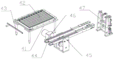
As shown in fig. 9 and 10, the coil body feeding device 4 includes a coil frame 41, a coil tray 42, a locking bar 43, a second motor 44, a coil body feeding rail 45, a conveying belt 46, and a coil body overturning mechanism 47; the tray rack 41 is arranged on the rack 14, the tray 42 is designed to be in a drawing type, the tray 42 is placed in the tray rack 41, and one end of the locking strip 43 is rotatably connected to the tray rack 41; the coil body feeding rail 45 is installed on the rack 14 and located beside the material tray frame 41, the second motor 44 and the conveying belt 46 are both installed on the coil body feeding rail 45, and the second motor 44 drives the conveying belt 46 to move so as to carry the coil body b on the conveying belt 46; the coil body overturning mechanism 47 is positioned at the discharge end of the coil body feeding track 45 and used for overturning the coil body b by 90 degrees, and then the coil body is clamped and conveyed to the jig body in the jig conveying device 3 by the third conveying manipulator device 6;
when the coil body feeding device 4 works, the coil body b is fully placed in the material tray 42, the locking bar 43 is rotated to lock the coil body b after the coil body b is placed on the material tray frame 41, then the coil body b is conveyed to the coil body feeding rail 45 from the material tray 42 by the second conveying manipulator device 5, and a row of workpieces in the material tray are conveyed at the same time each time; the coil body b in the coil body feeding rail 45 is driven by the second motor 44 to move towards the coil body turning mechanism 47, and finally, the coil body turning mechanism 47 turns the workpieces in the two coil body feeding rails 45 to be in a vertical state. The coil body overturning mechanism 47 is adopted to solve the problem that the coil body is difficult to load in a vertical state; the coil body feeding device 4 has the effects of improving the working efficiency of the machine and reducing the blockage in the feeding process.
The coil body overturning mechanism 47 can operate the two coil body feeding rails 45 at the same time, and specifically comprises an overturning seat 471, a rotating groove seat 472, a rotating block 473, a lifting slide rail 474, a rack 475, a gear 476 and a seventh cylinder 477; the turning seat 471 is arranged on the frame 14, and the rotary groove seat 472 is arranged on the turning seat 471; the rotating block 473 is provided with a coil slot 4731 which is matched with the shape of the coil body and used for placing the coil body; the rotating block 473 is rotatably connected to the rotating slot 472 through the pin 478; a gear 476 is mounted on the pin 478, a rack 475 is mounted on the lifting slide 474, and the rack 475 is meshed with the gear 476; the lifting slide rail 474 is vertically movably matched on the turnover seat 471, the seventh cylinder 477 is fixedly arranged on the turnover seat 471, the telescopic end of the seventh cylinder 477 is connected with the lifting slide rail 474, and the seventh cylinder 477 drives the lifting slide rail 474 to move up and down back and forth;
when the coil body turning mechanism 47 works, the coil body is horizontally placed in a feeding state, enters the coil slot of the transfer block 473, and is extended by the seventh air cylinder 477 to drive the rack 475 to ascend and drive the gear 476 to rotate by 90 degrees, so that the coil body is kept vertical to wait for the third carrying manipulator device 6 to grab. The coil body overturning mechanism 47 solves the problems that the coil body in a horizontal state is difficult to move and does not conform to the processing required state; coil body tilting mechanism 47's effect is that the material loading is more simple and convenient, the coil body level place can, the third transport manipulator device 6 of being convenient for moves and gets, has improved work efficiency and integration degree.
As shown in fig. 11, the second transfer robot apparatus 5 includes a transfer rack 51, a third motor 52, an eighth cylinder 53, a ninth cylinder 54, a pivoting jaw 55, a jaw swivel 56, a movable jaw mount 57, a movable jaw 58, a fixed jaw 59, and a traverse arm 510; the carrying bracket 51 is fixedly arranged on the frame 14; the transverse arm 510 is connected to the carrying bracket 51, the third motor 52 controls the transverse horizontal movement of the transverse arm 510, and the eighth cylinder 53 controls the vertical movement of the transverse arm 510; the ninth cylinder 54 is installed on the transverse arm 510, the telescopic end of the ninth cylinder 54 forms a moving groove pair connection with the connecting groove piece 511 at the upper end of the rotating clamping piece 55, the rotating clamping piece 55 is made of a magnet, the lower straight section of the rotating clamping piece 55 forms a rotating connection with the clamping piece rotating seat 56, and the clamping piece rotating seat 56 is installed on the transverse arm 510; the two ends of the movable chuck mounting seat 57 are mounted on the transverse arms 510, and the middle of the movable chuck 58 is rotatably connected to the movable chuck mounting seat 57; the movable chuck 58 is made of iron material, so that the magnet is easy to attract; a plurality of movable chucks 58 are arranged side by side, the width of each movable chuck is matched with the height of the coil body, and wedge grooves matched with the coil body are arranged at the lower ends of the movable chucks 58; the fixed jaw 59 is mounted on the traverse arm 510, and the lower end of the fixed jaw 59 is provided with a second wedge groove corresponding to the movable jaw 58.
When the second carrying manipulator device 5 works, the clamping work is completed by the ninth cylinder 54, when the ninth cylinder 54 extends, the rotating clamping piece 55 is driven to rotate clockwise around the shaft, the movable chuck 58 rotates clockwise around the shaft under the suction action of the rotating clamping piece 55 and the movable chuck 58, the lower end of the movable chuck 58 is close to the fixed chuck 59, so that the coil body arranged in the movable chuck is clamped, and when the ninth cylinder 54 is released, the coil body is contracted; after clamping, the third motor 52 and the eighth air cylinder 53 work together to convey the clamped workpiece from the tray 42 to the coil body feeding rail 45. The second carrying manipulator device 5 solves the problems that the coil body is small and exquisite in structure, difficult to carry and low in carrying efficiency; the number of the movable clamping heads 58 can be controlled to adapt to the number of one row of workpieces in the material tray; through the control of the ninth cylinder 54, a plurality of workpieces can be clamped, and the carrying efficiency is greatly improved.
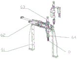
As shown in fig. 12, the third transfer robot device 6 is mounted on the rack 14; the third carrying manipulator device 6 realizes the gripping of the coil body b by the second finger cylinder 64, realizes the horizontal movement of the second finger cylinder 64 by the tenth cylinder 62, and realizes the vertical movement of the second finger cylinder 64 by the eleventh cylinder 63. The third transfer robot device 6 transfers the coil body in the coil body overturning mechanism 47 to the jig conveying device 3.
As shown in fig. 13, the iron core feeding device 7 includes a centrifugal disc 71, a vibration material rail 72, an iron core blanking seat 73, a twelfth air cylinder 74, a moving slot block 75, a mounting cover plate 76, a self-loosening block 77, a third optical fiber sensor 78 and a blanking joint 79; the centrifugal disc 71 is mounted on the mounting frame 710, the vibrating material rail 72 is connected with the centrifugal disc 71, and the vibrating material rail 72 is used for orderly vibrating and conveying the iron core; the iron core blanking seat 73 is arranged on the mounting frame 710, and the iron core blanking seat 73 is connected with the vibration material rail 72; the movable trough block 75 is movably matched in the iron core blanking seat 73, the twelfth air cylinder 74 is fixedly arranged on the mounting frame 710, and the telescopic end of the twelfth air cylinder 74 is connected with the movable trough block 75; the self-loosening block 77 is connected to the moving groove block 75, and a protruding roller is arranged on the self-loosening block 77; the mounting cover plate 76 is mounted on the iron core blanking seat 73, two inclined slotted holes 761 are formed in the mounting cover plate 76, and the protruding rollers on the self-loosening block 77 are positioned in the inclined slotted holes; a third optical fiber sensor 78 is mounted on the mounting cover plate 76 for detecting whether the iron core is in place; the blanking connector 79 is arranged below the iron core blanking seat 73, the blanking connector 79 is aligned with a blanking port 731 of the iron core blanking seat 73, the size of the blanking port 731 is matched with the size of an iron core, and the position of the blanking port 731 is staggered with a feeding port of the iron core blanking seat 73.
When the iron core feeding device 7 works, an iron core enters the moving groove block 75 through the vibrating material rail 72, the iron core is just clamped on the end part of the self-loosening block 77 due to the fact that the upper end of the iron core d is provided with a boss and cannot fall down, then the twelfth air cylinder 74 extends to push the moving groove block 75 outwards, the protruding roller at the upper end of the self-loosening block 77 is limited by the inclined groove hole in the mounting cover plate 76 to move backwards, the arc opening of the self-loosening block 77 is caused to retreat, the iron core d falls down just to the blanking opening of the iron core blanking seat 73, the blanking joint 79 is connected with a rubber pipe, and the iron core is moved to the iron core mounting device 8. The iron core feeding device 7 solves the problem of sorting of single iron cores in the iron core feeding process; the iron core feeding device 7 realizes two movements through the power input of a twelfth air cylinder 74, namely, the moving groove block 75 moves to correspond to the blanking port and the self-loosening block 77 moves to unlock the iron core, so that the iron core can fall.
As shown in fig. 14, the iron core mounting device 8 includes a lock nozzle mounting bracket 81, a lock nozzle 82, a thirteenth cylinder 83 and a push rod 84; the lock nozzle 82 is vertically installed on the rack 14 through the lock nozzle installation frame 81, a lock nozzle hole 821 is formed in the lock nozzle 82, the output end of the thirteenth air cylinder 83 is connected with the push rod 84, the push rod 84 is controlled by the thirteenth air cylinder 83 to move downwards, and the push rod 84 enables the iron core d on the lock nozzle 82 to be installed in a workpiece in the jig. The lock beak 82 is provided in two sets arranged in parallel, and the thirteenth cylinder 83 and the push rod 84 are provided in two sets matching the lock beak 82. When the iron core assembling jig is used, the iron core d enters the iron core d from the lock nozzle hole 821, then the thirteenth air cylinder 83 drives the push rod 84 to move downwards, and the iron core d is assembled in a workpiece in the jig.
As shown in fig. 15 to 18, the rivet pressing device 9 includes a fourth carrying robot mechanism 91, a positioning mechanism 92, a lower rivet assembly 93 and an upper rivet assembly 94; the lower riveting component 93 and the upper riveting component 94 are both arranged on the frame and are used together to realize riveting; the fourth carrying manipulator mechanism 91 is mounted on the upper riveting component 94 and is used for carrying the assembled workpiece to the positioning mechanism 92, waiting for riveting and carrying the riveted inductor piece to the finished product discharging device 10; the positioning mechanism 92 is installed on the rack, the positioning mechanism 92 is located between the lower riveting component 93 and the upper riveting component 94, and the positioning mechanism 92 is used for positioning the assembled inductor, so that the lower riveting component 93 and the upper riveting component 94 can work accurately. The press riveting device 9 solves the problem that the jig is directly pressed and riveted in the jig, and the position of the press riveting device deviates in the carrying process, so that the press riveting quality is improved, and the defective rate is reduced.
The four-conveying manipulator mechanism 91 comprises a third finger cylinder 913, a fourteenth cylinder 911 and a fifteenth cylinder 912, wherein the third finger cylinder 913 is used for clamping a workpiece, the fourteenth cylinder 911 is used for controlling the third finger cylinder 913 to vertically move longitudinally, and the fifteenth cylinder 912 is used for controlling the third finger cylinder 913 to horizontally move transversely.
The positioning mechanism 92 comprises a middle sliding plate 921, a movable carrier plate 922, a sixteenth air cylinder 923, a male positioning block 924, an eighteenth air cylinder 925 and a female positioning block 926; the middle sliding plate 921 is arranged on the frame 14, and the middle part of the middle sliding plate 921 is provided with a stop block; the movable carrier plate 922 is movably matched with the middle sliding plate 921, the sixteenth air cylinder 923 is installed on the rack 14, and the telescopic end of the sixteenth air cylinder 923 is connected with the movable carrier plate 922; the male positioning block 924 is arranged on the movable carrier plate 922, the female positioning block 926 is movably matched with the male positioning block 924, the shapes of the male positioning block 924 and the female positioning block 926 are matched with the shape of the inductor, and a limited area for placing the inductor is arranged on the movable carrier plate 922; an eighteenth air cylinder 925 is installed on the movable carrying platform plate 922, and the telescopic end of the eighteenth air cylinder 925 is connected with a female positioning block 926.
When the positioning mechanism 92 works, firstly, the eighteenth cylinder 925 drives the female positioning block 926 to move towards the male positioning block 924, so that the inductance position arranged in the middle of the female positioning block is limited; then, the sixteenth air cylinder 923 drives the movable carrier plate 922 to move to the round hole of the middle sliding plate 921, and the inductor is subjected to riveting by the lower riveting component 93 and the upper riveting component 94; because two workpieces are operated simultaneously, the directions of the workpieces are consistent, the positioning mechanism at the right end has the same working principle as the positioning mechanism at the left end, only the female positioning block is fixed, and the male positioning block is driven by the cylinder. Positioning mechanism 92 has solved the problem that the work piece is difficult to direct riveting on the carrier to and the problem that the precision is low among the riveting process: the positioning mechanism 92 has the effects that positioning is carried out before riveting, the yield of workpieces is improved, the positioning and clamping mechanism is simple in structure, and the fourth carrying manipulator mechanism 91 can be conveniently moved.
The lower riveting component 93 is mounted on the frame 14, and the top end of the lower riveting component is a riveting head which can be lifted and pressed against the lower end of the iron core to act together with the upper riveting component 94. The upper riveting assembly 94 comprises an eighteenth air cylinder 941, a lifting frame 942 and an upper riveting head 943; an eighteenth air cylinder 941 is installed on the rack through a connecting plate 944, a lifting frame 942 is movably matched on the connecting plate 944, the telescopic end of the eighteenth air cylinder 941 is connected with the lifting frame 942, and an upper riveting head 943 is installed on the lifting frame 942; the upper riveting head 943 is provided with a convex cylinder for pressing the iron core, and the shape of the upper riveting head 943 is matched with that of the male positioning block 924;
when the upper riveting component 94 works, the upper riveting head 943 is driven by the eighteen cylinders 941 to descend, and after the male positioning blocks 924 are embedded, the protruding cylinders of the upper riveting head 943 prop against the upper end of the iron core and are riveted with the lower riveting component 93 under the combined action.
As shown in fig. 19, the finished product discharging device 10 is connected to the rivet pressing device 9, and the fourth carrying robot mechanism 91 carries the finished product from the positioning mechanism 92; the finished product discharging device 10 comprises a discharging frame, a fourth motor 101, a discharging belt 102 and a blocking block 103, wherein the fourth motor drives the discharging belt 102 to move, and the blocking block 103 is used for blocking a workpiece vertically placed on the discharging belt 102, so that the workpiece falls into a horizontal state. The fourth motor drives the discharging belt 102 to move so as to carry the processed finished product on the discharging belt 102 to move for discharging, the blocking block 103 is located in the discharging direction of the discharging belt 102, and the blocking block 103 is used for blocking the upper end of the workpiece vertically placed on the discharging belt 102 to enable the workpiece to fall into a horizontal state.
When the electric inductor works, the elastic piece feeding device 1 is used for feeding the elastic pieces, the elastic pieces are conveyed to the jig conveying device 3 through the first conveying manipulator device 2, the jig conveying device 3 is used for circulating the jigs, and the electric inductor is assembled in a work step; secondly, the coil body feeding device 4 conveys workpieces on the coil body feeding device 4 of the coil body, and the second conveying manipulator device 5 conveys the workpieces; then the workpiece is conveyed to the jig through a third conveying manipulator device 6; then, the iron core is loaded by the iron core loading device 7, and the iron core is placed in a jig by the iron core loading device 8, so that the assembly of three inductance components is completed; then, after being carried out by the fourth carrying manipulator mechanism 91 of the press riveting device 9, the riveting device is pressed and fixed; finally, the fourth carrying manipulator mechanism 91 carries the processed finished product to the finished product discharging device 10, and the finished product discharging device 10 carries out the produced inductor.
Claims (4)
1. The coil body feeding device is characterized by comprising a coil frame (41), a material tray (42), a locking bar (43), a second motor (44), a coil body material passing rail (45), a conveying belt (46) and a coil body turnover mechanism (47); the material tray rack (41) is arranged on the rack (14), a material tray (42) is placed in the material tray rack (41), and one end of the locking strip (43) is rotatably connected to the material tray rack (41); the second motor (44) and the conveying belt (46) are both arranged on the coil body material passing rail (45), and the second motor (44) drives the conveying belt (46) to move so as to carry the coil body (b) on the conveying belt (46); the coil body overturning mechanism (47) is positioned at the discharge end of the coil body feeding rail (45) and used for overturning the coil body (b); the coil body overturning mechanism (47) comprises an overturning seat (471), a rotating groove seat (472), a rotating block (473), a lifting slide rail (474), a rack (475), a gear (476) and a seventh air cylinder (477); the turning seat (471) is arranged on the rack (14), and the rotating groove seat (472) is arranged on the turning seat (471); the rotating block (473) is provided with a coil slot (4731) which is matched with the shape of the coil body and used for placing the coil body; the rotating block (473) is rotatably connected to the rotating groove seat (472) through a pin shaft (478); the gear (476) is arranged on the pin shaft (478), the rack (475) is arranged on the lifting slide rail (474), and the rack (475) is meshed with the gear (476); the vertical removal cooperation of lift slide rail (474) is on upset seat (471), and seventh cylinder (477) is fixed to be set up on upset seat (471), and seventh cylinder (477) flexible end is connected with lift slide rail (474), and seventh cylinder (477) drives lift slide rail (474) back and forth movement from top to bottom.
2. The automatic assembly equipment for the inductance element is characterized by comprising a rack (14), and an elastic piece feeding device (1), a first carrying manipulator device (2), a jig conveying device (3), a second carrying manipulator device (5), a third carrying manipulator device (6), an iron core feeding device (7), an iron core loading device (8), a press riveting device (9) and a coil body feeding device (4) which are arranged on the rack; the first carrying manipulator device (2) is used for carrying the elastic sheets in the elastic sheet feeding device (1) to the jig conveying device (3); the second conveying manipulator device (5) is used for conveying the workpieces on the coil body feeding device (4); the third carrying manipulator device (6) carries the coil body on the coil body feeding device (4) into the jig conveying device (3); the iron core feeding device (7) conveys the iron core to the iron core loading device (8); the coil body feeding device comprises a coil frame (41), a material tray (42), a locking bar (43), a second motor (44), a coil body material passing rail (45), a conveying belt (46) and a coil body overturning mechanism (47); the material tray rack (41) is arranged on the rack (14), a material tray (42) is placed in the material tray rack (41), and one end of the locking strip (43) is rotatably connected to the material tray rack (41); the second motor (44) and the conveying belt (46) are both arranged on the coil body material passing rail (45), and the second motor (44) drives the conveying belt (46) to move so as to carry the coil body (b) on the conveying belt (46); the coil body overturning mechanism (47) is positioned at the discharge end of the coil body feeding rail (45) and used for overturning the coil body (b); the coil body overturning mechanism (47) comprises an overturning seat (471), a rotating groove seat (472), a rotating block (473), a lifting slide rail (474), a rack (475), a gear (476) and a seventh air cylinder (477); the turning seat (471) is arranged on the rack (14), and the rotating groove seat (472) is arranged on the turning seat (471); the rotating block (473) is provided with a coil slot (4731) which is matched with the shape of the coil body and used for placing the coil body; the rotating block (473) is rotatably connected to the rotating groove seat (472) through a pin shaft (478); the gear (476) is arranged on the pin shaft (478), the rack (475) is arranged on the lifting slide rail (474), and the rack (475) is meshed with the gear (476); the lifting slide rail (474) is vertically movably matched on the turnover seat (471), the seventh cylinder (477) is fixedly arranged on the turnover seat (471), the telescopic end of the seventh cylinder (477) is connected with the lifting slide rail (474), and the seventh cylinder (477) drives the lifting slide rail (474) to move up and down back and forth; the coil body material passing rail (45) is arranged on the rack (14).
3. The automatic inductance component assembling equipment according to claim 2, wherein the second carrying robot device (5) comprises a carrying bracket (51), a third motor (52), an eighth cylinder (53), a ninth cylinder (54), a rotating jaw (55), a jaw rotating base (56), a movable jaw mounting base (57), a movable jaw (58), a fixed jaw (59) and a traverse arm (510); the carrying bracket (51) is fixedly arranged on the frame (14); the transverse arm (510) is connected to the carrying bracket (51), the third motor (52) controls the transverse horizontal movement of the transverse arm (510), and the eighth cylinder (53) controls the vertical movement of the transverse arm (510); the ninth cylinder (54) is arranged on the transverse extending arm (510), the telescopic end of the ninth cylinder (54) forms a movable groove pair connection with a connecting groove piece (511) at the upper end of the rotating clamping piece (55), the rotating clamping piece (55) is made of a magnet, the straight section at the lower end of the rotating clamping piece (55) forms a rotating connection with the clamping piece rotating seat (56), and the clamping piece rotating seat (56) is arranged on the transverse extending arm (510); the movable chuck mounting seat (57) is mounted on the transverse arm (510), and the middle of the movable chuck (58) is rotatably connected to the movable chuck mounting seat (57); the movable chuck (58) is made of ferrous materials which are easy to attract by magnets; a plurality of movable chucks (58) are arranged side by side, the width of each movable chuck is matched with the height of the coil body, and wedge grooves matched with the coil body are arranged at the lower ends of the movable chucks (58); the fixed chuck (59) is arranged on the transverse arm (510), and the lower end of the fixed chuck (59) is provided with a second wedge groove corresponding to the movable chuck (58).
4. The automatic assembly equipment of the inductance component according to claim 2, characterized in that the spring piece loading device comprises a spring piece turnover mechanism (11), a vibration loading mechanism (12) and a spring piece sorting mechanism (13); the elastic piece turnover mechanism (11), the vibration material passing mechanism (12) and the elastic piece sorting mechanism (13) are sequentially connected and arranged along the elastic piece feeding direction; the elastic piece overturning mechanism (11) overturns the horizontally placed elastic piece (a) into a vertical elastic piece (a); the elastic sheet turnover mechanism (11) comprises a material changing seat (111), a rotating block (112), a first air cylinder (113), a second air cylinder (114) and a material pushing block (115); the rotating block (112) is connected with the material changing seat (111) through a pin shaft, and the rotating block (112) is positioned in the middle of the material changing seat (111); the lower end of the rotating block (112) is rotationally connected with the telescopic end of the first cylinder (113); the rotating block (112) is provided with a spring plate groove (1221) matched with the outer contour of the spring plate; the second air cylinder (114) is arranged on the material changing seat (111) through a second air cylinder mounting block (117), the material pushing block (115) is arranged on the telescopic end of the second air cylinder (114), the material pushing end of the material pushing block (115) is located in the material changing seat (111), and the material pushing end of the material pushing block (115) is matched with the elastic sheet groove (1221) of the rotating block (112); the vibrating material passing mechanism (12) comprises a first vibrating motor fixing seat (121), a first vibrating motor (122) and a material passing rail (123); the material passing rail (123) is arranged at the upper end of the first vibrating motor (122), and an L-shaped groove matched with the shape of the elastic sheet is formed in the material passing rail (123); the shrapnel sorting mechanism (13) comprises a shrapnel sorting base (131), a third air cylinder (132), a sorting block (133), a first linear sliding rail component (134) and a first optical fiber sensor (135); a sorting groove matched with the elastic sheet is formed in the sorting block (133), the sorting block (133) is movably connected to the elastic sheet sorting base (131) through a first linear slide rail assembly (134), and the thickness of the sorting block (133) is matched with the width of the elastic sheet; the third air cylinder (132) is arranged on the sorting base (131), and the telescopic end of the third air cylinder (132) is connected with the sorting block (133); the first optical fiber sensor (135) is arranged on the elastic piece sorting base (131), and the optical fiber head just divides the sorting block (133); the material changing seat (111) and the spring piece sorting base (131) are arranged on the rack (14); the first air cylinder (113) is connected to the frame (14) through a first air cylinder mounting block (116); the first vibration motor (122) is arranged on the rack (14) through a first vibration motor fixing seat (121).
Priority Applications (1)
| Application Number | Priority Date | Filing Date | Title |
|---|---|---|---|
| CN201810953788.6A CN108927646B (en) | 2018-09-26 | 2018-09-26 | Coil body feeding device and automatic inductance element assembling equipment |
Applications Claiming Priority (1)
| Application Number | Priority Date | Filing Date | Title |
|---|---|---|---|
| CN201810953788.6A CN108927646B (en) | 2018-09-26 | 2018-09-26 | Coil body feeding device and automatic inductance element assembling equipment |
Publications (2)
| Publication Number | Publication Date |
|---|---|
| CN108927646A CN108927646A (en) | 2018-12-04 |
| CN108927646B true CN108927646B (en) | 2020-04-17 |
Family
ID=64446217
Family Applications (1)
| Application Number | Title | Priority Date | Filing Date |
|---|---|---|---|
| CN201810953788.6A Active CN108927646B (en) | 2018-09-26 | 2018-09-26 | Coil body feeding device and automatic inductance element assembling equipment |
Country Status (1)
| Country | Link |
|---|---|
| CN (1) | CN108927646B (en) |
Families Citing this family (5)
| Publication number | Priority date | Publication date | Assignee | Title |
|---|---|---|---|---|
| CN109597294B (en) * | 2018-12-26 | 2020-07-03 | 厦门理工学院 | Automatic coil assembling machine for clock movement |
| CN109848686B (en) * | 2019-04-17 | 2020-05-26 | 湖州师范学院求真学院 | Full-automatic assembling equipment for inductor |
| CN110238650A (en) * | 2019-05-31 | 2019-09-17 | 成都九系机器人科技有限公司 | A kind of cable drum automatic setup system |
| CN111243841B (en) * | 2020-01-23 | 2020-10-27 | 温州职业技术学院 | Customized inductor assembly detection equipment |
| CN117253715B (en) * | 2023-11-20 | 2024-02-23 | 苏州砺宏电子设备有限公司 | Coil feeding machine and processing equipment of integrated inductor |
Citations (6)
| Publication number | Priority date | Publication date | Assignee | Title |
|---|---|---|---|---|
| US5558248A (en) * | 1993-09-10 | 1996-09-24 | Emhart Inc. | Headed rod member aligning and supply apparatus |
| CN102390095A (en) * | 2011-10-14 | 2012-03-28 | 周金生 | Feeding structure of stone sawing machine |
| CN206088347U (en) * | 2016-07-06 | 2017-04-12 | 吉林省金沙数控机床股份有限公司 | Feed bin on full -automatic disk type work |
| CN106865178A (en) * | 2017-04-07 | 2017-06-20 | 东方国际集装箱(连云港)有限公司 | It is a kind of to stablize feeding and possess the feed mechanism of turn over function |
| CN206305709U (en) * | 2016-11-09 | 2017-07-07 | 苏州迈威斯精密机械有限公司 | The plug feed mechanism of magnetic valve core assembly assembly machine |
| CN207658699U (en) * | 2017-12-21 | 2018-07-27 | 恩纳基智能科技无锡有限公司 | A kind of overturning feeding device |
-
2018
- 2018-09-26 CN CN201810953788.6A patent/CN108927646B/en active Active
Patent Citations (6)
| Publication number | Priority date | Publication date | Assignee | Title |
|---|---|---|---|---|
| US5558248A (en) * | 1993-09-10 | 1996-09-24 | Emhart Inc. | Headed rod member aligning and supply apparatus |
| CN102390095A (en) * | 2011-10-14 | 2012-03-28 | 周金生 | Feeding structure of stone sawing machine |
| CN206088347U (en) * | 2016-07-06 | 2017-04-12 | 吉林省金沙数控机床股份有限公司 | Feed bin on full -automatic disk type work |
| CN206305709U (en) * | 2016-11-09 | 2017-07-07 | 苏州迈威斯精密机械有限公司 | The plug feed mechanism of magnetic valve core assembly assembly machine |
| CN106865178A (en) * | 2017-04-07 | 2017-06-20 | 东方国际集装箱(连云港)有限公司 | It is a kind of to stablize feeding and possess the feed mechanism of turn over function |
| CN207658699U (en) * | 2017-12-21 | 2018-07-27 | 恩纳基智能科技无锡有限公司 | A kind of overturning feeding device |
Also Published As
| Publication number | Publication date |
|---|---|
| CN108927646A (en) | 2018-12-04 |
Similar Documents
| Publication | Publication Date | Title |
|---|---|---|
| CN108927646B (en) | Coil body feeding device and automatic inductance element assembling equipment | |
| CN109103008B (en) | Automatic assembling equipment for inductance element | |
| CN108857403B (en) | Elastic piece feeding device and automatic inductance element assembling equipment | |
| CN108698772B (en) | Full-automatic feeding assembly line | |
| CN112192103A (en) | Welding equipment for automatic and efficient welding of steel bars of invisible well lid | |
| CN109501115B (en) | Feeding and discharging system of injection molding machine | |
| CN106629042A (en) | Feeding method for full-automatic feeding assembly line | |
| CN109605663B (en) | Full-automatic pipe body injection head equipment and working method | |
| CN106865219B (en) | Automatic transfer chain | |
| CN108311631B (en) | Automatic riveting equipment for brush holder bottom plate and insulating plate | |
| CN211192779U (en) | O-shaped ring assembling machine | |
| CN109605662B (en) | Full-automatic feeding device and method for stacking and pushing type pipe body | |
| CN103010699A (en) | Tooling board delivering and taking circulating system | |
| CN111531787A (en) | Full-automatic hook assembling system | |
| CN105984708A (en) | Efficient and full-automatic complete-row supplying and collecting device | |
| CN108335899A (en) | A kind of equipment producing patch type inductance | |
| CN109332501B (en) | Inductance element pressing and riveting device and inductance element automatic assembling equipment | |
| CN111571068A (en) | Full-automatic welding device with multi-stage circulation and working method thereof | |
| CN109014819A (en) | Jig conveying device and inductance element automatic assembly equipment | |
| CN113369890A (en) | Motor stator assembling equipment | |
| CN109500598B (en) | Automatic assembling equipment of spoon | |
| CN108987093B (en) | Iron core hinged workpiece assembling equipment and assembling method thereof | |
| CN217577263U (en) | Material changing and transferring equipment | |
| CN215357172U (en) | Motor stator assembling equipment | |
| CN211916381U (en) | Automatic circular feeding and discharging system for disc part grinding |
Legal Events
| Date | Code | Title | Description |
|---|---|---|---|
| PB01 | Publication | ||
| PB01 | Publication | ||
| SE01 | Entry into force of request for substantive examination | ||
| SE01 | Entry into force of request for substantive examination | ||
| TA01 | Transfer of patent application right |
Effective date of registration: 20200323 Address after: 528300 Fu'an Industrial Zone, Leliu Town, Shunde District, Foshan City, Guangdong Province Applicant after: STEWARD (FOSHAN) MAGNETICS Co.,Ltd. Address before: 315301 No. 1600 West Third Ring Road, Zonghan Street, Cixi City, Ningbo City, Zhejiang Province Applicant before: Wang Jiahai |
|
| TA01 | Transfer of patent application right | ||
| GR01 | Patent grant | ||
| GR01 | Patent grant |