CN107249910B - Thermal conditioning system and method for a vehicle area - Google Patents
Thermal conditioning system and method for a vehicle area Download PDFInfo
- Publication number
- CN107249910B CN107249910B CN201580076477.0A CN201580076477A CN107249910B CN 107249910 B CN107249910 B CN 107249910B CN 201580076477 A CN201580076477 A CN 201580076477A CN 107249910 B CN107249910 B CN 107249910B
- Authority
- CN
- China
- Prior art keywords
- thermal
- conduit
- component
- vehicle
- transfer device
- Prior art date
- Legal status (The legal status is an assumption and is not a legal conclusion. Google has not performed a legal analysis and makes no representation as to the accuracy of the status listed.)
- Active
Links
Images


Classifications
-
- B—PERFORMING OPERATIONS; TRANSPORTING
- B60—VEHICLES IN GENERAL
- B60H—ARRANGEMENTS OF HEATING, COOLING, VENTILATING OR OTHER AIR-TREATING DEVICES SPECIALLY ADAPTED FOR PASSENGER OR GOODS SPACES OF VEHICLES
- B60H1/00—Heating, cooling or ventilating [HVAC] devices
- B60H1/00007—Combined heating, ventilating, or cooling devices
- B60H1/00021—Air flow details of HVAC devices
- B60H1/00028—Constructional lay-out of the devices in the vehicle
-
- B—PERFORMING OPERATIONS; TRANSPORTING
- B60—VEHICLES IN GENERAL
- B60H—ARRANGEMENTS OF HEATING, COOLING, VENTILATING OR OTHER AIR-TREATING DEVICES SPECIALLY ADAPTED FOR PASSENGER OR GOODS SPACES OF VEHICLES
- B60H1/00—Heating, cooling or ventilating [HVAC] devices
- B60H1/00271—HVAC devices specially adapted for particular vehicle parts or components and being connected to the vehicle HVAC unit
- B60H1/00285—HVAC devices specially adapted for particular vehicle parts or components and being connected to the vehicle HVAC unit for vehicle seats
-
- B—PERFORMING OPERATIONS; TRANSPORTING
- B60—VEHICLES IN GENERAL
- B60H—ARRANGEMENTS OF HEATING, COOLING, VENTILATING OR OTHER AIR-TREATING DEVICES SPECIALLY ADAPTED FOR PASSENGER OR GOODS SPACES OF VEHICLES
- B60H1/00—Heating, cooling or ventilating [HVAC] devices
- B60H1/00321—Heat exchangers for air-conditioning devices
-
- B—PERFORMING OPERATIONS; TRANSPORTING
- B60—VEHICLES IN GENERAL
- B60H—ARRANGEMENTS OF HEATING, COOLING, VENTILATING OR OTHER AIR-TREATING DEVICES SPECIALLY ADAPTED FOR PASSENGER OR GOODS SPACES OF VEHICLES
- B60H1/00—Heating, cooling or ventilating [HVAC] devices
- B60H1/32—Cooling devices
- B60H1/3204—Cooling devices using compression
-
- B—PERFORMING OPERATIONS; TRANSPORTING
- B60—VEHICLES IN GENERAL
- B60N—SEATS SPECIALLY ADAPTED FOR VEHICLES; VEHICLE PASSENGER ACCOMMODATION NOT OTHERWISE PROVIDED FOR
- B60N2/00—Seats specially adapted for vehicles; Arrangement or mounting of seats in vehicles
- B60N2/56—Heating or ventilating devices
- B60N2/5607—Heating or ventilating devices characterised by convection
- B60N2/5621—Heating or ventilating devices characterised by convection by air
-
- B—PERFORMING OPERATIONS; TRANSPORTING
- B60—VEHICLES IN GENERAL
- B60N—SEATS SPECIALLY ADAPTED FOR VEHICLES; VEHICLE PASSENGER ACCOMMODATION NOT OTHERWISE PROVIDED FOR
- B60N2/00—Seats specially adapted for vehicles; Arrangement or mounting of seats in vehicles
- B60N2/56—Heating or ventilating devices
- B60N2/5678—Heating or ventilating devices characterised by electrical systems
- B60N2/5685—Resistance
-
- B—PERFORMING OPERATIONS; TRANSPORTING
- B60—VEHICLES IN GENERAL
- B60N—SEATS SPECIALLY ADAPTED FOR VEHICLES; VEHICLE PASSENGER ACCOMMODATION NOT OTHERWISE PROVIDED FOR
- B60N2/00—Seats specially adapted for vehicles; Arrangement or mounting of seats in vehicles
- B60N2/56—Heating or ventilating devices
- B60N2/5678—Heating or ventilating devices characterised by electrical systems
- B60N2/5692—Refrigerating means
-
- B—PERFORMING OPERATIONS; TRANSPORTING
- B60—VEHICLES IN GENERAL
- B60H—ARRANGEMENTS OF HEATING, COOLING, VENTILATING OR OTHER AIR-TREATING DEVICES SPECIALLY ADAPTED FOR PASSENGER OR GOODS SPACES OF VEHICLES
- B60H1/00—Heating, cooling or ventilating [HVAC] devices
- B60H1/00007—Combined heating, ventilating, or cooling devices
- B60H1/00021—Air flow details of HVAC devices
- B60H2001/00185—Distribution of conditionned air
- B60H2001/00192—Distribution of conditionned air to left and right part of passenger compartment
-
- B—PERFORMING OPERATIONS; TRANSPORTING
- B60—VEHICLES IN GENERAL
- B60H—ARRANGEMENTS OF HEATING, COOLING, VENTILATING OR OTHER AIR-TREATING DEVICES SPECIALLY ADAPTED FOR PASSENGER OR GOODS SPACES OF VEHICLES
- B60H1/00—Heating, cooling or ventilating [HVAC] devices
- B60H1/00007—Combined heating, ventilating, or cooling devices
- B60H1/00021—Air flow details of HVAC devices
- B60H2001/00185—Distribution of conditionned air
- B60H2001/002—Distribution of conditionned air to front and rear part of passenger compartment
-
- B—PERFORMING OPERATIONS; TRANSPORTING
- B60—VEHICLES IN GENERAL
- B60H—ARRANGEMENTS OF HEATING, COOLING, VENTILATING OR OTHER AIR-TREATING DEVICES SPECIALLY ADAPTED FOR PASSENGER OR GOODS SPACES OF VEHICLES
- B60H1/00—Heating, cooling or ventilating [HVAC] devices
- B60H1/00007—Combined heating, ventilating, or cooling devices
- B60H1/00207—Combined heating, ventilating, or cooling devices characterised by the position of the HVAC devices with respect to the passenger compartment
- B60H2001/00228—Devices in the interior of the passenger compartment
-
- B—PERFORMING OPERATIONS; TRANSPORTING
- B60—VEHICLES IN GENERAL
- B60H—ARRANGEMENTS OF HEATING, COOLING, VENTILATING OR OTHER AIR-TREATING DEVICES SPECIALLY ADAPTED FOR PASSENGER OR GOODS SPACES OF VEHICLES
- B60H1/00—Heating, cooling or ventilating [HVAC] devices
- B60H1/00271—HVAC devices specially adapted for particular vehicle parts or components and being connected to the vehicle HVAC unit
- B60H2001/003—Component temperature regulation using an air flow
Landscapes
- Engineering & Computer Science (AREA)
- Mechanical Engineering (AREA)
- Physics & Mathematics (AREA)
- Thermal Sciences (AREA)
- Aviation & Aerospace Engineering (AREA)
- Transportation (AREA)
- Power Engineering (AREA)
- Air-Conditioning For Vehicles (AREA)
Abstract
Features of a vapor compression system configured to cool and/or heat (i.e., thermally condition) two or more distinct climate controlled vehicle interior components via a common thermal bus are disclosed. Some embodiments employ a single compressor. Some embodiments employ multiple compressors and/or thermal buses, each serving components located within a respective interior thermal zone of the vehicle, such as a front row seating zone, a second row seating zone, and/or a third row seating zone, and/or an overhead zone and/or a trunk zone.
Description
Cross Reference to Related Applications
This patent application claims priority to U.S. provisional patent application No. 62/094,852, filed on 12/19/2014 and 62/241,514, filed on 10/14/2015, the entire disclosure of each of which is incorporated herein by reference for all purposes.
Technical Field
The present disclosure relates generally to thermal systems, and more particularly to vapor compression systems for heating and cooling components of a vehicle.
Background
In many cases, it is desirable to thermally condition, i.e., heat and/or cool, components in a vehicle. In cold climates, a warm seat is desirable. In hot climates, it is desirable to have a cup holder that keeps the beverage cool. Various methods of thermally conditioning components within a vehicle are known. A method provides thermal conditioning for components in a vehicle using a radiator of the vehicle. This approach requires a complex arrangement to route the thermal medium, such as air or liquid, to various components within the vehicle interior. Other approaches use thermoelectric devices that are dedicated to target device regulation. However, such devices have limited power output and may require multiple devices to meet power requirements. Another approach uses large compressors that are dedicated to the components they regulate. For example, some vehicles use large compressors that are dedicated to individual components and cool them by conduction. Such systems are bulky and limited to servicing a single component. Further, such large compressors are noisy and must be acoustically isolated, such as with sound protection devices.
Disclosure of Invention
There is a need for a system for thermal conditioning of vehicle components that overcomes the shortcomings of conventional approaches. Several embodiments of a system for thermally conditioning various components in a vehicle are described herein. The system is configured to independently service various components under varying temperature and power requirements in cooperation with one or more similar or different convective (conductive) and conductive regulators. The thermally regulated component may be a seat and thermally convenient components such as a storage bin, a cup holder, or may be other components in a vehicle. In some embodiments, the system includes a thermal bus having a single main line for circulating a thermal medium, which may be a liquid or a gas.
The thermal medium may be heated or cooled by a vapor compression system having a micro-compressor, an evaporator, and a condenser. The micro-compressor may be any of a number of commercially available micro-compressors, and it may be a reciprocating, rotary screw (screw) type, centrifugal, scroll, or other. In some embodiments, the micro-compressor may have an output of about 100-300 watts. In some embodiments, the micro-compressor may have an output of about 100 watts. The miniature compression system may be relatively miniature, small, micro-or compact to fit into a desired/predetermined location, area or compartment (component) of a vehicle, such as, for example, a center console, dashboard, under a seat, etc. of the vehicle. In some embodiments, the micro-compressor has dimensions comparable to a twelve ounce soda can.
The vapor compression system is in thermal communication with one or more hot zones within the vehicle. The micro-compressor may have a variable speed control to vary the thermal energy provided to the thermal medium from the micro vapor compression system. To provide cooling, the evaporator of the vapor compression system is in thermal communication with the hot zone. To provide heating, the condenser of the vapor compression system is in thermal communication with the hot zone. Each thermal zone may include a heat transfer device (e.g., a heat exchanger) and a component to be heated or cooled. The branches from the main conduit serve different areas and are configured to circulate the thermal medium from the main conduit to the heat exchanger. Each of the branches may comprise a flow control device, such as a valve or a pump, configured to regulate the flow of the thermal medium through the branch and thereby control the temperature of the heat exchanger.
The hot zone may include a fan (e.g., a fluid moving device such as a fluid flow control device, including a pump) configured to blow air through the heat exchanger in an "open loop air" system, in which conditioned air is exhausted from the component, or in a "closed loop air" system, in which conditioned air is recirculated through the hot zone. The thermal region may also be a conductive region, wherein the heat exchanger and the component are in contact with each other such that the component is thermally conditioned via conduction (e.g., the heat exchanger (such as, for example, a plate) is in substantially direct thermal communication with the conditioned component). The system may also include a thermal battery coupled to the main conduit, the thermal battery providing thermal regulation when the vapor compression system is not operating. These are merely some aspects of the present disclosure and further aspects and details are provided herein.
Various embodiments of the present disclosure relate to a thermal conditioning system for heating or cooling within a thermal zone of a vehicle. The system may include the following: a fluid circuit configured to circulate a first working fluid in the fluid circuit; a thermal energy source in thermal communication with the fluid circuit, the thermal energy source configured to heat or cool the first working fluid; a first conduit (conduit) in fluid communication with the fluid circuit, the first conduit configured to convey at least some of the first working fluid in the first conduit; a first heat transfer device in thermal communication with the first conduit; a first component within a thermal zone of the vehicle, the first component in thermal communication with a first heat transfer device, wherein the first heat transfer device heats or cools the first component via thermal energy transferred from or to at least some of the first working fluid in the first conduit; a second conduit in fluid communication with the fluid circuit, the second conduit configured to convey at least some of the first working fluid in the second conduit; a second heat transfer device in thermal communication with the second conduit; and a second component within the thermal zone of the vehicle, the second component in thermal communication with the second heat transfer device, wherein the second heat transfer device heats or cools the second component via thermal energy transferred from or to at least some of the first working fluid in the third conduit.
In some embodiments, the thermal conditioning system may include one or more of the following: a third conduit in thermal communication with the first heat transfer device and the first component, wherein the first heat transfer device transfers thermal energy between the first conduit and the third conduit; the third conduit is configured to convey a second working fluid different from the first working fluid in the third conduit, the second working fluid being heated or cooled by the first heat transfer device via thermal energy transferred from or to the first working fluid in the first conduit; the first working fluid comprises a liquid and the second working fluid comprises air; a fan configured to move air in the third duct; a fan blowing air toward the first component without recirculating the air to heat or cool the first component; the first component includes a first seat, a cup holder, and a box of a seat of the vehicle; the third conduit is configured to recirculate air in the third conduit; a fan moves air in the second duct to heat or cool the first component; the first part comprises a housing (enclosure); a third conduit configured to recirculate air between the enclosure and the first heat transfer device; the first component comprises a housing and the third conduit is configured to recirculate air within the housing; the second conduit comprises a duct (duct) connected to a wall of the housing; the duct includes a first opening that draws air from the enclosure and a second opening that directs air into the enclosure; the fan is positioned at the first opening or the second opening; the second heat transfer device includes a conductive plate having a first surface configured to thermally connect to the second surface of the second component to form substantially direct thermal communication; the second member includes a cup holder of the vehicle; the thermal conditioning system includes a thermal battery and a fourth conduit in fluid communication with the fluid circuit, the fourth conduit configured to convey the first working fluid therein, the fourth conduit in thermal communication with the thermal battery; the thermal battery is configured to store thermal energy when the vehicle is operating and configured to release thermal energy when the vehicle is not operating; the thermal energy source comprises a vapor compression system; a fluid circuit in thermal communication with an evaporator of the vapor compression system to cool the first working fluid; a fluid circuit in thermal communication with a condenser of the vapor compression system to heat the first working fluid; the fluid circuit is selectively in thermal communication with an evaporator of the vapor compression system or a condenser of the vapor compression system to cool or heat, respectively, the first working fluid; the evaporator or condenser of the vapor compression system is positioned within a passenger compartment of the vehicle; the vapor compression system is positioned within a hot zone of the vehicle; a thermal zone contained within a passenger compartment of the vehicle, the thermal zone being smaller than the passenger compartment of the vehicle; a plurality of thermal conditioning systems are provided; a plurality of thermal conditioning systems are positioned within a passenger compartment of the vehicle; the thermal conditioning system includes an additional thermal energy source in selective thermal communication with the fluid circuit; other sources of thermal energy include a heat source configured to heat the first working fluid; the thermal conditioning system includes an additional thermal energy source in selective thermal communication with the first conduit; the other thermal energy source includes a heat source configured to heat the first working fluid in the first conduit to heat the first component; the second component is in substantially direct thermal communication with the second heat transfer device; the thermal conditioning system includes one or more temperature sensors configured to determine a temperature of at least one of the first component or the second component; the system is configured to heat or cool at least one of the first component or the second component to a predetermined temperature; the thermal conditioning system includes one or more temperature sensors configured to determine a temperature of at least one of the first heat transfer device or the second heat transfer device; the system is configured to heat or cool at least one of the first heat transfer device or the second heat transfer device to a predetermined temperature; the thermal conditioning system includes a temperature sensor configured to determine a temperature of the first working fluid; the system is configured to heat or cool the first working fluid to a predetermined temperature; and/or the second component comprises a second seat, cup holder, and bin of the vehicle seat different from the first seat, cup holder, and bin of the vehicle seat.
Various embodiments of the present disclosure relate to a system for thermally conditioning components in a vehicle having a central heating, ventilation, and air conditioning (central HVAC) system. The system may include the following: a thermal bus and a vapor compression system in thermal communication with the thermal bus. The thermal bus may include the following: a main line configured to circulate a thermal medium therethrough; a thermal zone comprising a first heat exchanger and a component; and a first branch coupled with the main conduit and configured to circulate at least some of the thermal medium from the main conduit to the thermal zone; a second thermal zone comprising a second heat exchanger and a second component; and a second branch coupled with the main conduit and configured to circulate at least some of the thermal medium from the main conduit to a second thermal zone. The vapor compression system is separate from the central HVAC system and may include the following: a micro compressor; a condenser coupled to the compressor; and an evaporator coupled to the condenser and the compressor, wherein the micro vapor compression system provides thermal energy to a thermal medium circulating in a main line of the thermal bus.
In some embodiments, a system for thermally conditioning a component may include one or more of the following. The thermal bus includes the following: a second thermal zone comprising a second heat exchanger and a second component; a second branch coupled with the main conduit and configured to circulate a thermal medium from the main conduit to a second thermal zone; the thermal bus comprises a third thermal zone comprising a third heat exchanger and a third component; a third branch coupled with the main conduit and configured to circulate a thermal medium from the main conduit to a third thermal zone; the first member and the second member are two of a seat, a box (bin), and a cup holder; the first component is a seat; the second component is a tank; the third member is a cup holder; a system for thermally conditioning a component includes a vehicle; the thermal bus and the micro vapor compression system are installed in a vehicle; the micro-compressor has a variable speed to vary the thermal energy provided to the thermal medium from the micro vapor compression system; the first branch includes a valve, and the first branch circulates the thermal medium in proximity to the heat exchanger, and the valve is configured to regulate a flow of the thermal medium therethrough, and thereby control a temperature or other heat transfer performance of the heat exchanger; the thermal medium is a liquid; the hot zone includes a fan configured to blow air through the heat exchanger; the hot zone is an open loop air system configured to exhaust conditioned air therefrom; the hot zone includes a fan configured to blow air through the heat exchanger; the hot zone is a closed loop air system configured to recirculate the conditioned air; the heat exchanger and the component are in contact with each other such that the component is thermally conditioned via conduction; the condenser is configured to be integrated with a vehicle air conditioning system; and/or the system for thermally conditioning a component includes a thermal battery coupled to the main conduit.
Various embodiments of the present disclosure relate to a thermal conditioning system for heating or cooling within a thermal zone of a vehicle. The system may include the following: a first fluid circuit of the vapour compression system, and the first fluid circuit may be configured to circulate a first working fluid in the first fluid circuit; a first heat transfer device in thermal communication with the first fluid loop, the vapor compression configured to heat or cool the first heat transfer device via a first working fluid in the first fluid loop; a second fluid circuit configured to circulate a second working fluid in the second fluid circuit, the second fluid circuit in thermal communication with the first heat transfer device to heat or cool the second working fluid via thermal energy transferred from or to the first working fluid; a first conduit in fluid communication with the second fluid circuit, the first conduit configured to convey a second working fluid in the first conduit; a second heat transfer device in thermal communication with the first conduit; a second conduit in thermal communication with a second heat transfer device, wherein the second heat transfer device transfers thermal energy between the first conduit and the second conduit; a first component within a thermal zone of the vehicle, the first component in thermal communication with the second conduit, wherein the second conduit heats or cools the first component via thermal energy transferred from or to the second working fluid in the first conduit by a second heating device; a third conduit in fluid communication with the second fluid circuit, the third conduit configured to convey a second working fluid in the third conduit; a third heat transfer device in thermal communication with the third conduit; and a second component within the thermal zone of the vehicle, the second component in substantially direct thermal communication with the third heat transfer device, and the third heat transfer device may heat or cool the second component by transferring thermal energy between the second working fluid in the third conduit and the second component.
In some embodiments, a thermal conditioning system for heating or cooling within a thermal zone of a vehicle may include one or more of the following. The first working fluid comprises a refrigerant of a vapor compression system; the second working fluid comprises ethylene glycol; the first heat transfer device comprises a condenser or an evaporator of the vapor compression system; the condenser or evaporator is configured to heat or cool, respectively, a second working fluid via a first heat transfer device; the vapor compression system is reversibly operated to perform as a condenser or an evaporator for the first heat transfer device; the system includes a fourth heat transfer device in thermal communication with the second fluid circuit; a fourth heat transfer device in thermal communication with the first heat transfer device to transfer thermal energy between the first working fluid and the second working fluid; the fourth heat transfer device comprises a conductive plate in substantially direct thermal communication with the first heat transfer device; the second conduit is configured to convey a third working fluid in the second conduit; the third working fluid is heated or cooled by the second heat transfer device via thermal energy transferred from or to the second working fluid in the first conduit; the third working fluid comprises air; the system includes a fan configured to move air in the second duct; a fan blowing air toward the first component without recirculating the air to heat or cool the first component; the first component comprises a seat of the vehicle; the second conduit is configured to recirculate air in the second conduit; a fan moves air in the second duct to heat or cool the first component; the first component includes a housing; a second conduit configured to recirculate air within the enclosure; the second conduit comprises a tube connected to a wall of the housing; the duct comprises a first opening for drawing air from the enclosure and a second opening for directing air back into the enclosure; the fan is positioned at the first opening or the second opening; the third heat transfer device includes a conductive plate having a first surface configured to thermally connect to the second surface of the second component to form substantially direct thermal communication; the second member includes a cup holder of the vehicle; the system includes a thermal battery and a fourth conduit in fluid communication with the second fluid circuit; the fourth conduit is configured to convey a second working fluid in the fourth conduit; a fourth conduit in thermal communication with the thermal battery; the thermal battery is configured to store thermal energy when the vehicle is operating and configured to release thermal energy when the vehicle is not operating; the evaporator or condenser of the vapor compression system is positioned within a passenger compartment of the vehicle; the thermal zone is contained within a passenger compartment of the vehicle; the hot zone is smaller than the passenger compartment of the vehicle; a plurality of thermal conditioning systems are provided; a plurality of thermal conditioning systems are positioned within a passenger compartment of the vehicle; one or more systems include a thermal energy source in selective thermal communication with the second fluid circuit; the thermal energy source comprises a heat source configured to heat the second working fluid; one or more systems include a thermal energy source in selective thermal communication with the first conduit; the thermal energy source comprises a heat source configured to heat the second working fluid in the first conduit to heat the first component; the one or more systems include one or more temperature sensors configured to determine a temperature of at least one of the first component or the second component; the system is configured to heat or cool at least one of the first component or the second component to a predetermined temperature; the one or more systems include one or more temperature sensors configured to determine a temperature of at least one of the second heat transfer device or the third heat transfer device; the system or systems are configured to heat or cool at least one of the second heat transfer device or the third heat transfer device to a predetermined temperature; and/or the system or systems include a temperature sensor configured to determine a temperature of the second working fluid, and the system or systems are configured to heat or cool the second working fluid to a predetermined temperature.
The foregoing is a summary and contains, by necessity, simplifications, generalizations, and omissions of detail. Those skilled in the art will appreciate that the summary is illustrative only and is not intended to be in any way limiting. Other aspects, features, and advantages of the devices and/or processes and/or other subject matter described herein will become apparent in the teachings set forth herein. This summary is provided to introduce a selection of concepts in a simplified form that are further described below in the detailed description. This summary is not intended to identify key features or essential features of any subject matter described herein.
This summary is provided to introduce a selection of concepts in a simplified form that are further described below in the detailed description. This summary is not intended to identify key features or essential features of any subject matter described herein.
Drawings
Non-limiting and non-exhaustive embodiments will be described with reference to the following figures, wherein like reference numerals refer to like parts throughout the various views unless otherwise specified.
FIG. 1A is a side view of an embodiment of a system for thermally servicing a vehicle having a thermal system that services various components in various thermal zones of the vehicle.
FIG. 1B is a top view of the system of FIG. 1A.
FIG. 2 is a perspective view of an embodiment of various vehicle components served by a thermal bus that may be used in the system of FIG. 1A.
Fig. 3A-3B are perspective views of embodiments of thermal conditioning devices of a thermal bus that may be used in the system of fig. 1A.
Fig. 4A-4B are perspective views of another embodiment of a thermal conditioning device of a thermal bus that may be used in the system of fig. 1A.
FIG. 5A is a perspective view of an embodiment of a vehicle center console area having a thermal bus with a bin, cup holder, and thermal energy source that can be used in the system of FIG. 1A.
Fig. 5B and 5C are perspective and exploded views, respectively, of the case of fig. 5A.
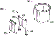
Fig. 5D and 5E are perspective and exploded views, respectively, of the cup holder of fig. 5A.
Fig. 5F is a perspective view of an embodiment of a thermal energy source that may be used in the system of fig. 1A.
Fig. 6 is a schematic diagram of an embodiment of a thermal bus that may be used in the system of fig. 1A, the thermal bus having a micro vapor compression system as a source of thermal energy and a single thermal medium line serving three different thermal zones.
FIG. 7 is a schematic view of an embodiment of a miniature vapor compression system that may be used in the system of FIG. 1A.
FIG. 8 is a schematic diagram of an embodiment of a control system for controlling a thermal conditioning system.
FIG. 9 is a schematic view of another embodiment of a thermal conditioning system.
Detailed Description
Reference throughout this specification to "one embodiment" or "an embodiment" means that a particular feature, structure, or characteristic described in connection with the embodiment is included in at least one embodiment of claimed subject matter. Thus, appearances of the phrases "in one embodiment" or "an embodiment" in various places throughout this specification are not necessarily all referring to the same embodiment. Furthermore, the particular features, structures, or characteristics may be combined in one or more embodiments (e.g., some embodiments).
The systems and methods disclosed herein provide features for thermal conditioning of components in a vehicle using a vapor compressor. Although presented in the context of a vehicle, similar systems may also be used in other contexts, such as homes and offices. The system includes at least one area having one or more components served by a thermal energy source using, for example, a vapor compressor. In some embodiments, the system has two, three, or more zones, where each zone has several components that are thermally conditioned. The system may include a single fluid loop for servicing one or more zones and components therein. In some embodiments, a single circuit circulates a liquid thermal medium to each of one or more zones, the liquid thermal medium conditioned by a vapor compression system, such as a micro vapor compressor, as a source of thermal energy. The liquid medium branches from the loop to each zone. Each zone may include a heat transfer device (e.g., a heat exchanger) that transfers heat to or from various components. For example, a first area may have a seat, a second area may have a storage bin in a center console, and a third area may have a cup holder. A single liquid medium circuit may serve all three zones. Further, each zone may be thermally conditioned with its respective components using various mechanisms, including "open-loop air," "closed-loop air," conductive, or other types, including fluid thermal systems having circuits and conduits that transport, for example, liquids. The adjustment may be controlled such that the component is heated or cooled to a predetermined temperature. In some embodiments, the conditioning systems disclosed herein may be controlled using the various methods and techniques disclosed in U.S. provisional patent application No. 62/241,514, filed on 14/10/2015, which is incorporated by reference herein in its entirety.
As used herein, the terms "line," "loop," and similar terms and phrases are used in their broad and ordinary sense and include, for example, any suitable line (piping), pipe, circuit, conduit, channel, passageway, etc. for conveying and/or conducting a desired medium or fluid (e.g., liquid, gas, coolant, air). As used herein, the term "coolant" and similar terms and phrases are used in their broad and ordinary sense and include, for example, fluids that transfer thermal energy within a heating or cooling system, such as refrigerants or glycols. As used herein, the term "heat transfer device" or "heat exchanger" and similar terms and phrases are used in their broad and ordinary sense and include, for example, heat exchangers, heat transfer surfaces, heat transfer structures, heat exchanger fins, and other suitable devices for transferring thermal energy between media, or any combination of such devices. As used herein, the terms "thermal energy source" and "heat source" and similar terms and phrases are used in their broad and ordinary sense and include, for example, condensers, vehicle engines, combustors, electronic components, heating elements, batteries or battery packs, exhaust system components, devices that convert energy into thermal energy, or any combination of such devices. In some embodiments, the terms "thermal energy source" and "heat source" may refer to a negative thermal energy source, such as, for example, a cooling device, an evaporator, another cooling component, a combination of components, and so forth.
As used herein, the terms "sufficient" and "substantially" and similar terms and phrases are used broadly in accordance with their ordinary meaning. For example, in the context of sufficient heating or sufficient heat transfer involving a fluid, these terms broadly include, but are not limited to, a condition in which the fluid, component, or area is heated to a temperature predetermined or desired by a user, such as, for example, an occupant of a vehicle, or a state in which the fluid, component, or area is heated to a threshold temperature.
As used herein, the term "actuator" or "fluid flow control device" and similar terms and phrases are used broadly in accordance with their ordinary meaning. For example, the term broadly includes fluid control devices such as, for example, valves, regulators, pumps, and other suitable structures, or combinations of structures for controlling fluid flow.
As used herein, the term "control device" and similar terms and phrases are used broadly in accordance with their ordinary meaning. For example, such terms and phrases broadly include a device or system configured to control fluid movement, electrical energy transfer, thermal energy transfer, and/or data communication between one or more components. The control device may comprise a single controller that controls one or more components of the system, or it may comprise more than one controller that controls various components of the system.
Fig. 1A-1B illustrate an embodiment of a system 1 for thermally servicing a vehicle 10 having thermal buses 20, 40, the thermal buses 20, 40 servicing various components in various thermal zones 22, 42 of the vehicle 10. The vehicle 10 may be a sedan, a truck, a sport utility vehicle, a semi-truck, a limousine, a mobile agricultural or construction vehicle, or any other suitable vehicle. The vehicle 10 may be propelled by an internal combustion engine, an electric motor, or a combination thereof. The system 1 may be operated during operation (e.g., moving) of the vehicle 10 and/or while the vehicle 10 is not being operated (e.g., stationary). During periods when the vehicle 10 is not operating, the system 1 may be powered by a vehicle power source (such as an on-board battery) or by an internal combustion engine or an electric motor driven generator. In this manner, the system 1 may provide an engine-off thermal management system for, for example, a passenger compartment, bed, chiller, or other area of a commercial or over-the-highway truck.
The system 1 includes a first thermal bus 20 located in a first thermal zone 22 of the vehicle 10. The first thermal bus 20 is a system for servicing components located within the first thermal zone 22. As shown, the components in the first thermal zone 22 include a first front seat 24 and at least a portion of a front row passenger compartment within a front passenger compartment of the vehicle 10. The front passenger compartment may be a location of the vehicle 10 where a driver is seated and driving the vehicle 10 or where front passengers are seated and riding together. Bus 20, zone 22, and seat 24 are shown in phantom because they are internal to vehicle 10. The first thermal zone 22 may also include other components of the vehicle 10. The first thermal bus 20 serves the components 22 in the first thermal zone 22 by heating or cooling them. For example, the first thermal bus 20 may circulate a thermal medium for cooling the first front seat 24. The first thermal bus 20 may further circulate a thermal medium for cooling other components within the first thermal zone 22. In some embodiments, the first thermal bus 20 may circulate a thermal medium for heating in addition to or instead of cooling. Thus, as used herein, "thermal service" and similar phrases include providing a thermal medium for cooling and/or heating.
The system 1 comprises a first control module 6. As shown, the first control module 6 may be located on or near the first front seat 24. However, the first control module 6 may be in any number of locations, such as another location of the seat 24, on an instrument panel, center console, steering wheel, or other location in the vehicle 10. The first control module 6 may be used to control the thermal conditioning of components within the first thermal zone 22. For example, the first control module 6 may be used to adjust the service performed by the first thermal bus 20 to the seat 24. If the seat 24 is too cold, it may be warmer using the first control module 6. If the seat 24 is too hot, it may be made cooler by using the first control module 6. Likewise, other components may be serviced in this manner. Further, the first control module 6 may be used to adjust thermal regulation of components within other thermal zones of the vehicle 10. There may also be a plurality of control modules 6.
The first control module 6 may include a user interface that may be accessed by a user of the system 1 to adjust the heat output to the various components. The interface may be any number of suitable user interfaces, such as a digital interface with touch screen input and/or many other components, including a rotating knob, a flipping switch, a pressed button or buttons, etc. The first control module 6 may further have or be coupled with a display that displays the current settings for thermal conditioning. For example, the digital display may display the temperature at which the seat 24 is set, along with the current temperature of the seat 24, and other suitable information. The display may also be in a different location than the first control module 6, such as an instrument panel or integrated with various instrument panels of the vehicle.
The first control module 6 may include various electronic and/or computing components. Those skilled in the art will recognize that the term "control module" as used herein, which may be part of or include a processor executing code, an Application Specific Integrated Circuit (ASIC), an electronic circuit, a combinational logic circuit, a Field Programmable Gate Array (FPGA), a hardwired feedback control circuit, other suitable components that provide the described functionality, or a combination of some or all of the foregoing. The control unit may further comprise a memory (shared, dedicated or group) that stores code executed by the control unit. Thus, in some embodiments, the first control module 6 may include a microprocessor, memory storage, and programs to execute control logic. The first control module 6 may receive inputs from a plurality of sensors and may adjust various operating parameters of the system 1 based on such inputs. Any suitable control algorithm may be implemented. The first control module 6 may be coupled with various sensors and/or devices of the first thermal zone 22, such as with thermal sensors or micro compressors, heat transfer devices, etc., to adjust the thermal output to certain components. In some embodiments, the first control module 6 may be in proximity to or part of an electronic control unit or module of the vehicle 10 for controlling various operations of the vehicle 10 over, for example, a Controller Area Network (CAN) bus of the vehicle 10. Further details of various sensors and devices that may be coupled with control module 6 are discussed herein, e.g., with respect to fig. 8.
As shown, the system 1 includes a second thermal zone 42. In some embodiments, the system 1 may include only one thermal zone or more than two thermal zones. As shown, the second thermal zone 42 includes a first rear seat 44 and is at least a portion of a rear passenger compartment of the vehicle 10. The rear passenger compartment may be a second or third row seating area behind the front row seating area, with one or more passengers seated in the rear of the vehicle 10. As shown in fig. 1A, the system 1 also includes a second thermal bus 40 located within a second thermal zone 42 and separate from the first thermal bus 20. The second thermal bus 40 thermally services various components of the vehicle 10 within a second thermal zone 42. The second thermal bus 40 and the second thermal zone 42 are similar to the first thermal bus 20 and the first thermal zone 22, except that the second system 40 and the second zone 42 serve different components of the vehicle 10. As shown, the second thermal bus 40 serves the first rear seat 44. The second thermal bus 40 may also serve other components of the vehicle 10 within a second thermal zone 42.
The system 1 comprises a second control module 8. The second control module 8 may be similar to the first control module 6. In some embodiments, the second control module 8 is used to control the thermal settings of components within the second thermal zone 42. For example, the second control module 8 may be used to adjust the service of the first rear seat 44 by the second thermal bus 40. The second control module 8 may also be used to control the thermal service of components outside the second thermal zone 42, instead of or in addition to components within the second thermal zone 42. As shown, the second control module 8 may be located on or near the first rear seat 44. However, the second control module 8 may be in any number of locations. The second control module 8 may further have any or all of the same features and functionality as the first control module 6, including but not limited to electronic control components and/or configurations discussed in further detail herein, e.g., with respect to fig. 8.
The thermal bus 20, 40 of the system 1 may be indirectly or directly thermally coupled with a condenser or radiator 2 located outside the passenger compartment in the engine compartment, for example at the front of the vehicle. The condenser 2 may be part of a thermal energy source 604, as discussed in further detail herein, e.g., with respect to fig. 6. In some embodiments, the heat sink 2 may be a condenser 720 of the miniature vapor compression system 700, as discussed in further detail herein, e.g., with respect to fig. 7. The condenser or radiator 2 may be located in front of or otherwise near the engine radiator. The heat sink 2 may be a heat transfer device such as, for example, a cryogenic core. Thus, ambient air may pass through the condenser or radiator 2 to remove thermal energy, wherein the condenser or radiator 2 provides a heat sink to the environment. The condenser or radiator 2 may exhaust or radiate heat absorbed by the thermal bus 20, 40 from devices and components therein (e.g., thermal energy transferred to the thermal bus 20, 40). As shown, the system 1 may be thermally coupled to the battery 4. The battery 4 may be a thermal battery, as discussed in further detail herein, e.g., with respect to fig. 6. The battery 4 may be thermally coupled with the thermal buses 20, 40 such that the main conduits within each bus 20, 40 circulate a thermal medium through the battery for thermal energy storage.
Fig. 1B is a top view of the system 1. As shown, the system 1 includes multiple components of a vehicle 10 served by a single thermal bus within a single thermal zone. The first thermal bus 20 services various component(s) within the first thermal zone 22. These components include a first front seat 24 as well as a second front seat 25 and a first center console 26. The first front seat 24 may be a driver-side seat in a front seating area of the vehicle 10. The second front seat 25 may be a passenger-side seat in the front seating area of the vehicle 10. A center console 26 is located between the two front seats 24, 25 and includes a first box 28. The first tank 28 includes a compartment for cooling and/or heating items that is thermally serviced by the first thermal bus 20. The first thermal bus 20 provides a thermal medium for cooling or heating the compartment or compartments within the first tank 28. The first center console 26 also includes a first cup holder 30 for cooling and/or heating the beverage. The first cup holder 30 is served by the first thermal bus 20. For example, the first thermal bus 20 may provide a thermal medium for cooling or heating the first cup holder 30.
The system 1 further comprises a first thermal energy source 32. As shown, the first thermal energy source 32 may be located in the first center console 26, on the first center console 26, or otherwise located with the first center console 26. The first thermal energy source 32 provides thermal energy to the thermal medium of the first thermal bus 20. Thus, in some embodiments, the first thermal energy source 32 is located within the first center console 26 and is in thermal communication with the first thermal bus 20. In some embodiments, the first thermal energy source 32 may be located within the first thermal zone 42. The first thermal bus 20 thermally services the first front seat 24, the second front seat 25, the first bin 28, and the first cup holder 30 using a first thermal energy source 32. Thus, the first thermal bus 20 may serve a plurality of components of the vehicle 10 within the first thermal zone 22. In some embodiments, the first thermal energy source 32 may serve components of the vehicle 10 outside of the first thermal zone 22, for example, by serving as a backup thermal energy source for components in the second thermal zone 42. In some embodiments, the first thermal energy source 32 may directly serve the vehicle components in the second thermal zone 42 (e.g., act as the primary thermal energy source for the vehicle components in the second thermal zone 42).
Similarly, the second thermal bus 40 may service one or more components of the vehicle 10, which may be within the second thermal zone 42. As shown, the second thermal bus 40 serves a first rear seat 44, a second rear seat 45, and a second center console 46. Further, the second center console 46 includes a second bin 48 and a second cup holder 50. The second thermal bus 40 may be thermally coupled to a second thermal energy source 52, which second thermal energy source 52 may be located within the second center console 46. The second thermal bus 40 may be in thermal communication with a second thermal energy source 52 and use energy from the energy source 52 to service various components of the second thermal zone 42. As shown, the second thermal bus 40 can thermally service the first rear seat 44, the second rear seat 45, the second bin 48, and the second cup holder 50 using thermal energy from the second thermal energy source 52. The first rear seat 44 may be a driver side rear seat in the vehicle 10. The second rear seat 45 may be a passenger side rear seat in the vehicle 10. In some embodiments, the second thermal bus 40 may use thermal energy from the first thermal energy source 32 alone or in combination with other thermal energy sources, such as the second thermal energy source 52.
In some embodiments, there may be fewer or more than two thermal zones 22, 42 and/or two thermal buses 20, 40. For example, there may be a third thermal zone and/or a third thermal bus. The third thermal zone and the third thermal bus may thermally service other areas of the vehicle, such as a third row seating area, trunk, components in doors, and so forth.
Fig. 2 is a perspective view of an embodiment of a thermal zone 200, the thermal zone 200 including various components served by a thermal bus 205 that may be used in the vehicle 10 of the system 1 shown in fig. 1A-1B. As shown in fig. 2, the thermal zone 200 includes a thermal bus 205. The components served by the thermal bus 205 include a seat 210 and a center console 220, the center console 220 including a bin 230 and two cup holders 240.
The components shown in hot zone 200 may be located within an interior compartment of a vehicle. For example, the seat 210 and center console 220 may be within the vehicle 10 of FIG. 1A. As shown in fig. 2, the seat 210 is positioned adjacent to a center console 220. The center console 220 includes a box 230 located near the rear of the center console 220. The cup holder 240 is located in front of the bin 230 in the center console 220.
As shown, the thermal energy source 250 is located in front of the cup holder 240. In some embodiments, the thermal energy source 250 may be positioned elsewhere on the vehicle while remaining sufficiently close to the thermally conditioned components to achieve thermal conditioning as discussed herein. The thermal energy source 250 is in thermal communication with the thermal medium of the thermal bus 205. Thus, the thermal energy source 250 absorbs or provides thermal energy to the thermal medium of the thermal bus 205. The thermal energy source 250 absorbs heat from the thermal bus 205 to provide cooling and provides heat to the thermal bus 205 to provide heating. In this manner, the thermal energy source 250 provides thermal energy to the thermal bus 205 for servicing the components of the seat 210 and the center console 220. The thermal bus 205 may service these components via, for example, a single fluid line or loop extending to the thermal energy source 250, as discussed in further detail herein, e.g., with respect to fig. 6. The single fluid line or circuit may be a loop system that recirculates a cooling medium or fluid, such as, for example, a coolant. Further details of thermal systems and thermal energy sources that may be used in the thermal zone 200 are provided herein, for example, with respect to fig. 6 and 7. The zone 200 shown in FIG. 2 is only one example of a possible arrangement of components and thermal buses 205 within the thermal zone 200. Other suitable configurations may be implemented.
The seat 210 may include an occupant-supporting surface having a plurality of thermal conditioning regions 212. The region 212 is a portion of the seat 210 that is thermally conditioned, such as by conduction, convection (convection), or a combination of both. By "thermally conditioned" is meant that the region 212 is thermally cooled or heated. Further, the area 212 is the primary location that is thermally conditioned, but other portions of the seat may also receive such thermal conditioning. As shown, the seat 210 has perforations or other openings in the thermal conditioning area 212 on the seat bottom portion 214 and on the seatback portion 216 through which conditioned air passes. The perforations in the region 212 are arranged in a substantially linear configuration along the length of the portions 214, 216. This arrangement is merely one example, and the perforations within the thermal conditioning region 212 may be arranged in a number of different configurations within or on the seat 210. Further, the conditioning area 212 may be implemented in a variety of ways other than using perforations. In some embodiments, the conditioning region 212 may include other openings, such as slots, and/or other components that condition and/or distribute conditioned air, such as a heating pad. Thus, the conditioning region 212 may include portions of various thermally conditioned components other than those immediately adjacent to the conditioning region 212. Further details of such embodiments, such as those including a heater mat, are discussed herein, for example, with respect to fig. 6.
The bin 230 is a device within the center console 220 that allows for storage of items to be thermally conditioned. In some embodiments, the tank 230 may be an integral cooler in the vehicle, such as with thermal insulation, within which items may be placed to keep cool or warm. The box 230 may also be an enclosure. In some embodiments, the box 230 is an enclosure that can be opened and closed to access the interior of the enclosure. The box 230 includes a thermal conditioning region 232. The zone 232 is thermally regulated by the thermal bus 205. Thus, the region 232 may be a cooling volume within the tank 230. For example, the area 232 may be a cavity defined by the box 230 in which beverages and other items may be placed to remain cool or warm.
The cup holder 240 includes a thermal conditioning area 242 within the respective beverage receptacle (receptacle). As shown, there are two cup holders 240 and two areas 242, with each cup holder 240 having an area 242. The region 242 is thermally regulated by the thermal bus 205. The thermal bus 205 provides heating and/or cooling for items placed within the thermal conditioning region 242. For example, a cup may be placed within the region 242 and kept cool or heated by the thermal bus 205.
The thermal energy source 250 provides thermal energy to the thermal bus 205 to thermally service these and other components. The energy source 250 may use a liquid thermal medium within a single conduit to service the seat 210, bin 230, and cup holder 240. Further details of the thermal bus 205 and the thermal energy source 250 that may be implemented within the thermal zone 200 are discussed herein, e.g., with respect to fig. 6 and 7.
Fig. 3A-3B are perspective views of an embodiment of a thermal conditioning device 300 according to the present disclosure and that may be used in the system 1 of fig. 1A-1B, the thermal conditioning device 300 may be coupled to a thermal bus. The thermal conditioning device 300 may service a vehicle seat back or bottom by providing conditioned air to a thermal conditioning area of the seat. For example, the thermal conditioning device 300 may be part of the first front seat 24 or any other seat. As another example, the thermal conditioning device 300 may also be part of the seatback portion 216 to provide thermally conditioned air to the conditioning zone 212, as shown in fig. 2.
As shown in fig. 3A, the thermal conditioning device 300 includes a cover 310. The cover 310 encapsulates the internal components of the thermal conditioning device 300. The depicted cover 310 encapsulates the heat transfer device 320 and the fan 330, the heat transfer device 320 may be a heat exchanger. In fig. 3B, the cover 310 has been removed from the thermal conditioning device 300. As shown, the heat transfer device 320 includes a convective heater substrate 325. Other heat transfer device components may be implemented. Fan 330 draws air through inlet 350 and pushes the air through heat transfer device 320 where the air is conditioned and exits through outlet 352. In some embodiments, device 320 may also incorporate a thermoelectric device ("TED").
The thermal conditioning device 300 may also include piping to receive and/or circulate the thermal medium therein. As shown, the thermal conditioning device 300 may include a first conduit 302 and a second conduit 304. The thermal medium may be in thermal communication with and thermally conditioned by a thermal energy source, such as thermal energy source 250 of fig. 2, and the thermal medium is circulated to thermal conditioning device 300 through first conduit 302 and may exit through second conduit 304. The lines 302, 304 may be coupled with inlet and outlet lines of a corresponding thermal energy source, such as the inlet line 580 and the outlet line 582 of the thermal energy source 570 described with respect to fig. 5F. The thermal medium may be used by the heat transfer device 320 to exchange heat. Thus, the conduits 302, 304 may extend along, adjacent to, on, or otherwise proximate to the heat transfer device 320 such that the conduits 302, 304, or extensions thereof, are in thermal communication with the heat transfer device 320. In some embodiments, first conduit 302 and second conduit 304 may be both ends of the same single conduit extending through thermal conditioning device 300. The configuration shown is merely an example, and other suitable arrangements may be implemented, such as more than two conduits 302 and 304, and/or located elsewhere on thermal conditioning device 300.
Fig. 4A-4B are perspective views of an embodiment of a thermal conditioning device 400 that may be used in the system 1 of fig. 1A-1B. For example, the thermal conditioning device 400 may be part of the first front seat 24 or any of the other seats 25, 44, 45. As another example, the thermal conditioning device 400 may also be part of the seat bottom portion 214 shown in fig. 2.
As shown in fig. 4A-4B, the thermal conditioning device 400 includes an adjustable channel 415 connecting the duct 420 to a fan 430. The fan 430 moves air through the adjustable passage 415 and into the inlet 450 of the duct 420. Adjustable channel 415 may be flexible such that it may be twisted, oriented, moved, or positioned into different configurations. As shown, the channel 415 is generally straight, but it may also be curved or a combination of straight, curved, curvilinear, and the like. After flowing through adjustable passage 415, the air flows through tubing 420 and through heat transfer device 460 (see fig. 4B), which heat transfer device 460 may be a conductive plate, such as a cold plate. As the air moves through the heat transfer device 460, the air is conditioned, for example, the air may be cooled by a cold plate. The air then moves through the duct 420 and exits through the outlet 452. As shown in fig. 4B, conduit 420, heat transfer device 460, and/or other components may be covered by housing 410. In some embodiments, thermal conditioning device 400 may also incorporate a thermoelectric device ("TED"). The TED may also be covered by the housing 410.
The thermal conditioning device 400 may also include one or more conduits to receive and/or circulate a thermal medium therein. The thermal medium may be in thermal communication with and thermally conditioned by a thermal energy source, such as thermal energy source 250 of fig. 2, and circulated through the conduit into thermal bus 205. The lines may be coupled with inlet and outlet lines of a corresponding thermal energy source, such as the inlet line 580 and the outlet line 582 of the thermal energy source 570 described with respect to fig. 5F. The thermal medium may be used by the heat transfer device 460 to exchange heat. For example, heat transfer device 460 may be cooled by a thermal medium (e.g., thermal energy is transferred from heat transfer device 460 to the thermal medium) such that air is cooled as it flows through heat transfer device 460. The cooled air may then flow to thermally condition the component.
The thermal conditioning device 300, 400 may be an "open loop air" system that does not reuse thermally conditioned air. For example, the thermal conditioning devices 300, 400 may move thermally conditioned air, such as cooled or warmed air, through an area of the seat and out of the seat, such as through the thermal conditioning area 212 of the seat 210 shown in fig. 2. This is in contrast to "closed loop air" systems, which reuse conditioned air, as further described herein, e.g., with respect to fig. 5B and 5C. However, an "open-loop air" system is only one example of subsystems 300 and 400 that may be implemented. Other suitable systems may also be implemented for the seat, such as a "closed loop air" system, conductive plates, or other systems described herein.
FIG. 5A is a perspective view of an embodiment of a vehicle center console thermal subsystem 500 that may be used in the system of FIG. 1A. As shown, the center console thermal subsystem 500 includes a bin 510, two cup holders 540, and a thermal energy source 570. The bin 510, cup holder 540, and/or thermal energy source 570 can be used in the center console 220 of fig. 2 or the center consoles 26, 46 of fig. 1A-1B. Details of the tank 510 are further described with respect to fig. 5B and 5C. Further details of the cup holder 540 are discussed with respect to fig. 5D and 5E. The thermal energy source 570 is discussed in further detail with respect to fig. 5F.
Fig. 5B and 5C are perspective and exploded views, respectively, of the case 510 of fig. 5A. As shown in fig. 5B, the box 510 includes a structural body 512. The body 512 defines a cavity 514 on the interior of the tank 510. The cavity 514 is a thermal conditioning area in which items placed therein may be thermally conditioned. Thus, the cavity 514 may be similar to the thermal conditioning region 232 of fig. 2. As further shown in fig. 5B, the box 510 includes a thermal conditioning device 520. The thermal conditioning device 520 forms part of a thermal bus that serves a plurality of components. For example, the thermal conditioning device 520 may be part of the first thermal bus 20 or the second thermal bus 40 of fig. 1A-1B. Further, thermal conditioners 300, 400 and 520 may all be part of the same thermal bus, such as thermal bus 20 or thermal bus 40.
Referring now to FIG. 5C, a thermal conditioning device 520 is shown in exploded view. The thermal conditioning device 520 includes a grill 522. The grill 522 is mounted in or on the tank 510, such as along an interior wall of the structural body 512. The grill 522 provides a series of openings for air to enter and/or exit the chamber 514 of the box 510.
As shown, thermal conditioning device 520 also includes a heat transfer device 524, such as a heat exchanger. A heat transfer device 524 is positioned adjacent to the grill 522. The heat transfer device 524 thermally conditions the air blown into the box 510. The thermally conditioned air is blown into the box 510 by a fan 526 adjacent to the heat transfer device 524. For example, air may be drawn from tank 510 through heat transfer device 524 to be heated or cooled by heat transfer device 524, and then blown back into tank 510 by fan 526.
The fan 526 blows the thermally conditioned air into the duct 528. The conduit 528 defines a channel for air to flow through. The conduit 528 recirculates air from inside the cavity 514 of the tank 510. For example, air from inside the cavity 514 may flow through an inlet defined by an upper segment of the grate 522 and into the conduit 528. The air may then be blown by a fan 526 through the heat transfer device 524 and into the outlet defined by the lower section of the grate 522 such that the thermally conditioned air is provided back to the cavity 514 of the tank 510. Thus, the thermal conditioning device 520 is a "closed loop air" system. This is but one example of how tank thermal conditioning device 520 may be implemented with tank 510. Other types of thermal systems (such as the "open loop air" subsystems 300, 400 described with respect to fig. 3A-4B), conductive plates, or others described herein may also be implemented.
Fig. 5D and 5E are perspective and exploded views, respectively, of one of the cup holders 540 of fig. 5A. The cup holder 540 includes a cup receptacle or cup insert (insert) 542. The cup insert 542 defines a cavity 544 on the interior of the cup holder 540. The cavity 544 is a location where an item, such as a cup, may be placed for thermal conditioning thereof. For example, a cup may be placed within the cavity 544 to maintain cooling or warming. Further, the cavity 544 may be the thermal conditioning region 242 of fig. 2.
As shown in fig. 5D, the cup holder 540 includes a thermal regulating device 550 that can be mounted on a portion of the cup insert 542. The cavity 544 is thermally conditioned by the subsystem 550 via conduction between the cup insert 542 and the thermal conditioning device 550. By thermally conditioning insert 542, cavity 544 and any items therein will also be thermally conditioned.
Fig. 5E is an exploded view of the cup holder 540 and the thermal conditioning device 550. The thermal conditioning device 550 includes a heat transfer device 552, such as a conductive plate, and a mounting housing 554. Heat transfer device 552 may directly contact cup insert 542 to have substantially direct thermal communication with cup insert 542. Thermal energy, such as heat, may be removed from cup insert 542 or added to cup insert 542 by conduction through adjacent contacting heat transfer devices 552, e.g., via two facing contact surfaces of cup insert 542 and heat transfer devices 552. Heat transfer device 552 may have a mounting housing 554 mounted thereto. The mounting housing 554 may have an insulating material (insulation) to prevent heat loss or heat exchange between the heat transfer device 552 and the ambient environment outside of the cup insert 542.
The thermal conditioning device 550 may also include one or more conduits to circulate a thermal medium therethrough. As shown in fig. 5D and 5E, subsystem 550 may include first and second conduits 553 and 555 fluidly coupled to a conductive plate 556 (see fig. 5E), which conductive plate 556 may be a hollow conductive plate. A thermal medium can be received from a thermal energy source (such as thermal energy source 250 of fig. 2), and can be circulated to thermal conditioning device 550 through first conduit 553 and conductive plate 556 and can exit through second conduit 555. The lines 553, 555 may be coupled with inlet and outlet lines of a corresponding thermal energy source, such as the inlet line 580 and the outlet line 582 of the thermal energy source 570 described with respect to fig. 5F. The thermal medium may be used by a heat transfer device 552, such as a conductive plate 556, to exchange heat. Thus, conduits 553, 555 may extend along heat transfer device 552, adjacent heat transfer device 552, on heat transfer device 552, or otherwise proximate heat transfer device 552 such that conduits 521, 525, or extensions thereof, are in thermal communication with heat transfer device 552. In some embodiments, first conduit 553 and second conduit 555 can be two ends of the same single conduit that extends through thermal conditioning device 550. The configuration shown is merely an example, and other suitable arrangements may be implemented, such as more than two conduits 553, 555 and/or at other locations of thermal conditioning device 550. Further, thermal conditioning device 550, along with thermal conditioning devices 300, 400, and/or 520, may all be part of (e.g., in thermal communication with) the same thermal bus, such as thermal bus 20 or thermal bus 40 shown in fig. 1A-1B. Thermal conditioning devices 300, 400, 520, and/or 550 may also be thermally coupled to (e.g., in thermal communication with) the same thermal energy source (e.g., thermal energy source 570 discussed below with respect to fig. 5F).
Fig. 5F is a perspective view of an embodiment of a thermal energy source 570 according to the present disclosure, the thermal energy source 570 can absorb heat from or provide heat to a thermal bus. The thermal energy source 570 may be used in the thermal zone 200 of fig. 2 or the system 1 of fig. 1A-1B. The thermal energy source 570 is configured to be in thermal communication with the thermal bus, and more specifically, the thermal medium is used to condition various thermal zones of the vehicle and various components therein. The thermal energy source 570 provides thermal energy for heating and/or cooling the thermal medium. Further details of the thermal energy source 570 interacting with the various thermally regulated components are provided herein, e.g., with respect to fig. 6 and 7.
As shown, the thermal energy source 570 is coupled to an inlet line 580, an outlet line 582, and a conductive plate 584, which may be a hollow conductive plate 584. The heat medium flows into the conductive plate 584 via the inlet line 580 and out of the conductive plate 584 via the outlet line 582. The conduits 580, 582 may be coupled directly or indirectly with corresponding conduits on the component to be thermally conditioned. For example, lines 580, 582 may be coupled with lines 302, 304 of thermal conditioning device 300 of fig. 3A-3B, and/or with lines 400 of fig. 4A-4B, and/or with lines 521, 525 of thermal conditioning device 520 of fig. 5B-5C, and/or with lines 553, 555 of thermal conditioning device 550 of fig. 5D-5E. The thermal energy source 570 further includes a micro compressor 572. The energy source 570 may have a total volume of about 512 cubic inches. For example, the energy source 570 may generally occupy an area or volume of about 8 x 8 inches. Other sizes may be accommodated, such as, for example, having a size (e.g., side area or volume) ranging from about 4 inches to 12 inches.
The thermal energy source 570 further includes a condenser 574 and an evaporator 576. The condenser 574 and the evaporator 576 are coupled to a micro-compressor 572. The condenser 574 or evaporator 576 provides thermal energy to the medium circulating through lines 580, 582. As shown, evaporator 576 serves as a source of thermal energy to provide cooling. In some embodiments, condenser 574 is used as a source of thermal energy to provide heating. As shown, the evaporator 576 may be in direct contact with the conductive plate 584 such that heat is conductively absorbed by the evaporator 576 from the conductive plate 584, thereby removing heat from the conductive plate 584, i.e., cooling the conductive plate 584. The thermal energy source 570 may also include a fan 578. A fan 578 may move air through the condenser 574 to remove heat rejected by the condenser 574. Other methods of removing heat rejected by condenser 574 can be implemented, and are discussed in further detail herein, e.g., with respect to fig. 1A and 7.
Thus, the conductive plate 584 is in thermal communication with the evaporator 576. As mentioned, heat can be removed from the conductive plate 584 through the evaporator 576. In this manner, the conductive plate 584 may be used to provide heating or cooling to the thermal medium circulating in the lines 580, 582. The component of the thermal energy source 570 used to provide cooling or heating to the conductive plate 584 may be what may be referred to as a "micro vapor compression system". Further details of the miniature vapor compression system and its interaction with a thermal bus for thermal conditioning of various vehicle components are discussed herein, for example, with respect to fig. 6 and 7.
FIG. 6 is a schematic view of an embodiment of a thermal conditioning system for heating or cooling multiple thermal zones or regions of a vehicle. The thermal conditioning system includes a thermal bus 600 having a thermal medium, the thermal bus 600 being conditioned by a thermal energy source 604 comprising a micro vapor compression system. The thermal bus 600 includes a single main or loop 605 that serves three different zones 601, 602, 603 within the vehicle. The bus 600 and thermal energy source 604 may be used in various embodiments for thermally conditioning one or more components in a vehicle, for example it may be used in the system 1 of fig. 1A-1B, the thermal zone 200 such as for the thermal bus 205 in fig. 2, or other embodiments described herein.
As shown, thermal bus 600 includes a first zone 601, a second zone 602, and a third zone 603. The areas 601, 602, 603 each include corresponding components of the vehicle being thermally conditioned, such as a seat, a bin, and a cup holder. For example, the first region 601 may correspond to the first front seat 24 from fig. 1A-1B or the seat 210 from fig. 2. The second region 602 may correspond to the first tank 28 of FIG. 1B or the tank 230 of FIG. 2. The third area 603 may correspond to the first cup holder 30 of fig. 1B or the cup holder 240 of fig. 2. As shown in fig. 6, the regions 601, 602, 603 are represented by dashed lines surrounding the various components included in the respective regions. Further details of the various components within each region 601, 602, 603 are discussed below, however, these are merely examples, and regions 601, 602, 603 may include fewer or more components than shown and described herein. Further, in some embodiments, there may be more or less than three zones. There may be one, two, four, or more zones in the thermal bus 600.
As shown, the thermal bus 600 includes a thermal medium that is heated and/or cooled by a thermal energy source 604. The thermal energy source 604 may be similar to the thermal energy source 570 described with respect to fig. 5F. The thermal energy source 604 may provide heating or cooling via an evaporator or condenser of the vapor compression system. In some embodiments, an evaporator is used in the thermal energy source 604 to provide cooling. In some embodiments, a condenser is used in the thermal energy source 604 to provide heating. Further details of thermal energy source 604 are described herein, e.g., with respect to fig. 7.
As shown in fig. 6, the thermal bus 600 has a single main line or loop 605 carrying a thermal medium that is heated and/or cooled by a thermal energy source 604 and used to condition the different zones 601, 602, 603. For example, conduit 605 is a tube or line that includes conduits that carry a fluid, such as a liquid, air, steam, or other thermal medium, to different zones. A conduit 605 extends in a loop from the thermal energy source 604 and returns to the thermal energy source 604. The conduit 605 may be in thermal communication with the thermal energy source 604 at various locations. In some embodiments, a portion of the line 605 may be in thermal communication with an evaporator of the thermal energy source 604 and another portion of the line 605 may be in thermal communication with a condenser of the thermal energy source 604. The valve may control the portion of line 605 that receives the working fluid. In this way, the thermal energy source may selectively provide heating or cooling. Such systems may be selectively controlled, for example, by the control system 800, as described herein.
The thermal bus 600 further includes various temperature sensors. As shown, an output temperature sensor 607 may be coupled to the line 605 at a location adjacent to the thermal energy source 604 (e.g., downstream in the direction of flow of the thermal medium through the line 605). The output temperature sensor 607 senses the temperature of the thermal medium in the line 605 when the thermal medium is out of thermal communication with the thermal energy source 604. As shown, the lead-in temperature sensor 608 can be coupled to the conduit 605 at a location adjacent to the thermal energy source 604 (e.g., upstream in the flow direction). As the thermal medium comes into thermal communication with the thermal energy source 604, the lead-in temperature sensor 608 senses the temperature of the thermal medium in the line 605. The sensors 607, 608 may be used to determine whether adjustments to the thermal energy source 604 are necessary. For example, if the temperature sensed by the sensors 607, 608 is too low or too high, the operation of the thermal energy source 604 may be adjusted to increase or decrease the amount of heating or cooling provided, respectively, and thereby adjust the temperature of the thermal medium.
As shown, the thermal bus 600 may also include a bypass 609. The bypass line 609 may be a continuation of the line 605 beyond the three zones 601, 602, 603. Bypass line 609 may also be a separate line coupled to line 605. The bypass line 609 may include a flow control device 610, such as a valve or other device that regulates the flow of the thermal medium through the bypass line 609. In some embodiments, the flow control device 610 is normally open. As discussed herein, bypass line 605 may be used to help regulate thermal conditioning of zones 601, 602, 603.
In some embodiments, flow control device(s) in other portions of the bus 600 may be used to control the flow into the bypass line 609. For example, flow control device(s) in line 605 or other lines may be used to control the flow into bypass line 609. Flow into and/or through the bypass line 609 may be passively (passively) controlled. For example, the flow into and/or through the bypass line 609 may be controlled by varying the size of the piping in the bypass line 609. For example, a smaller diameter segment in the portion(s) of the bypass tube 609 may provide a flow restriction to the bypass tube 609. Such restrictions may be substantially the same as other conduits.
As shown, the bypass line 609 may be connected to a heat battery 611. The thermal battery 611 is heated or cooled, i.e. thermally charged, by the thermal energy source 604. The thermal battery 611 may regulate one or more of the internal components during periods when the thermal energy source 604 is not operating. The thermal battery 611 may be charged through a bypass line 609 via one or more of a refrigerant circuit, a liquid circuit, and an air circuit, such as the main line 605. The thermal battery 611 may be a reservoir within the bypass line 609. The thermal battery 611 may be cooled by the thermal medium in the bypass line 609. The thermal battery 611 may be used to provide a lesser amount of cooling to the bus 600. For example, if the car is parked, the auxiliary pump may be operated to provide some thermal conditioning for various components of the vehicle. As another example, when the bus 600 is providing cooling, a fan may be run for a period of time after the vehicle has been turned off to provide air to and prevent icing of the evaporator in the thermal energy source 604. In some embodiments, the thermal battery 611 may be or include a thermal storage device, for example, including either or both of a high temperature phase change material and a low temperature phase change material, such as, for example, wax (higher temperature phase change material) and water (lower temperature phase change material), to store thermal energy for later use.
The first zone 601 receives the thermal medium flowing from the conduit 605 through the first branch 612. The first branch 612 includes a fluid flow control device 614, such as, for example, a valve. The flow control device 614 is configured to control, direct, enable, disable, prevent, or otherwise regulate the flow of the thermal medium through the first branch 612 to the first zone 601. In some embodiments, the flow control device 614 may be selectively opened and/or closed to regulate the flow of media through the first branch 612. Further, the flow control device 614 may be configured to be normally closed and then opened as needed. In some embodiments, an inline plunger pump (in-line pump) may be used in place of the flow control device 614 or the flow control device 614 works with an inline plunger pump for variable control. Commercially available pumps may be used, such as, for example, Micro AC/DC water pumps manufactured by Alita Industries, inc.
The first region 601 includes a heat transfer device 616, a fan 618, and a first thermal node 628, such as a seat in a vehicle. The thermal medium in the first branch 612 is circulated to the heat transfer device 616. The heat transfer device 616 is a heat exchanger or other similar device configured to exchange heat between the thermal medium within the first branch 612 and air supplied to the first thermal node 628 by the fan 618. For example, heat transfer device 616 may have a plurality of fins coupled to branches 612 through, over, around, or otherwise in proximity to which air flows. The thermal medium then flows through and out of the heat transfer device 616 in the first branch 612 and reconnects with the main conduit 605, with the thermal medium returning to the thermal energy source 604 through the main conduit 605.
The heat transfer device 616 is in thermal communication (e.g., thermally coupled or connected) with the first branch 612 such that the thermal medium flowing through the first branch 612 thermally conditions a fluid (such as air) flowing through an adjacent or conditioning pipe 620 (such as a pipe) that is in thermal communication (e.g., thermally coupled or connected) with the heat transfer device 616. As shown, a conduit 620 connects the fan 618 to the heat transfer device 616. A fan 618 blows air through the conduit 620 so that the air is thermally conditioned by the heat transfer device 616.
The temperature of the heat transfer device 616 is dependent upon a predetermined or desired temperature point set for the first thermal node 628. The desired temperature may be set, for example, using the control means 6, 8 of fig. 1A. Based on the set temperature, a specific amount of thermal power (i.e., thermal energy transfer with respect to time) may be applied. For example, for the first node 628, the temperature of the heat transfer device 616 may be set at twenty-six degrees celsius (26 ℃) and set to deliver sixty watts (60W) of thermal power to the first node 628. A dedicated control valve, such as the flow control device 614, may be selectively opened and closed to regulate the temperature of the heat transfer device 616. In some embodiments, the temperature of the heat transfer device 616 may be limited to maintain condensation products below a predetermined amount that may evaporate inside the vehicle. The temperature limit may be based on sensors providing data on the ambient air temperature and/or humidity. The desired temperature may affect the working fluid temperature (e.g., heat medium temperature) as well as the flow rate of the working fluid. For example, the working fluid temperature and flow rate may depend on the peak or total thermal power demand. The temperature of the conditioned fluid (such as air blown out of the first node 628, such as a seat) may depend on the desired temperature of the node 628. Further details of control systems that may be implemented are discussed herein, e.g., with respect to FIG. 8.
The thermally conditioned air then flows out of heat transfer device 616 and into conduit 626, which conduit 626 thermally connects heat transfer device 616 to a first thermal node 628. The thermally conditioned air then circulates through the first thermal node 628 and exits the first thermal node 628, as shown. In this manner, a person near first thermal node 628 (such as a person sitting in a seat) may receive cooling air. For example, the first branch 612 may have a cold thermal medium flowing to the heat transfer device 616 such that air blown through the heat transfer device 616 by the fan 618 via the conduit 620 is cooled. The cooled air then flows through the conduit 626 to the first thermal node 628. First thermal node 628 may comprise various portions of a single component. For example, for a vehicle seat, first thermal node 628 may include seat bottom portion 214 and/or seatback portion 216 of fig. 2. In some embodiments, the first thermal node 628 may include a fan therein similar to fan 618 to facilitate movement of conditioned air through node 628. Further, the first thermal node 628 may be a vent positioned separate from the occupant and blowing conditioned air toward the occupant. For example, the first thermal node 628 may be a vent positioned separate from the seat.
In some embodiments, the first region 601 also includes a heater mat 630 having a first thermal node 628. The heater mat 630 may be used to provide heat to the first thermal node 628. The cushion 630 may heat conditioned air or unconditioned air that is blown through the cushion 630 and around the cushion 630. The pad 630 may be used to heat air that has been cooled to remove moisture to a desired temperature for conditioning the first thermal node 628.
The first region 601 also includes various temperature sensors. As shown, a first temperature sensor 622 is located at the thermal transfer device 616. For example, temperature sensor 622 senses the temperature of heat transfer device 616 for diagnostic/operational purposes. If the temperature is too high or too low, adjustments may be made to the bus 600, such as adjustments to the thermal energy source 604 or maintenance or repair of a portion of the bus 600. The second temperature sensor 624 may be connected to a conduit 626, the conduit 626 extending from the heat transfer device 616 to a first thermal node 628. The second temperature sensor 624 senses the temperature of fluid, such as air, flowing through the conduit 626 for similar diagnostic/operational purposes. This is merely one example of how various temperature sensors may be arranged for providing temperature feedback and control, and other suitable configurations may be implemented. Further, there may be one, three or more such sensors located within the first region 601. The temperature sensors 622, 624 may provide feedback to a control system that may adjust the level of thermal conditioning provided, as discussed in further detail herein, e.g., with respect to fig. 8.
The first zone 601 is shown as an "open-loop air" system. However, other types of systems, such as "closed loop air" systems, or other systems as discussed herein, may be implemented. The second zone 602 is shown as such a "closed loop air" system. That is, the air used in the second zone 602 is recirculated and reused within the second zone 602 and does not exit the second zone 602 as air in the "open-loop air" first zone 601.
The second zone 602 is regulated by a second branch 632 connected to the line 605. The second branch 632 includes a fluid flow control device 634, such as, for example, a valve, which fluid flow control device 634 may be similar to the flow control device 614 in the first region 601, or may be a pump or other fluid movement device. The flow control device 634 controls, directs, allows, inhibits, prevents, or otherwise regulates the flow of the thermal medium circulating through the second branch 632 and to the second zone 602.
The second zone 602 includes a heat transfer device 636, a fan 638, and a second node 648 (such as, for example, a tank). The tank may be a storage vessel, a cooler, or the like. In some embodiments, the second node 648 is a bin 510.
The heat transfer device 636 is a heat exchanger or similar device configured to transfer heat between the thermal medium within the second branch 632 and the air circulated by the fan 638. The heat transfer device 636 may be similar to the heat transfer device 616 in the first zone 601. As shown, the second branch 632 extends through the heat transfer device 636 and exits the heat transfer device 636 and reconnects with the line 605, which returns the thermal medium to the thermal energy source 604. The thermal medium circulates from line 605 to heat transfer device 636 through second branch 632 and back to line 605. The heat transfer device 636 thermally conditions the second zone 602 using a thermal medium. The temperature of the heat transfer device 636 is dependent upon a set, predetermined, or desired temperature point of the second thermal node 628. For example, the desired temperature may be set using the control devices 6, 8 of fig. 1A. Based on the set temperature, a specific amount of thermal power (i.e., thermal energy transfer with respect to time) may be applied. For example, the temperature of the heat transfer device 636 used to regulate the second node 648 may be set to four degrees celsius (4 ℃) and provide forty watts (40W) of thermal power. Similar control as described with respect to the first region 601 may be implemented with the second region 602.
As shown, a fan 638 blows air through a duct 640 connected to a heat transfer device 636. Air blown through the heat transfer device 636 by the fan 638 via the duct 640 is thermally conditioned by the heat transfer device 636 and then exits the heat transfer device 636 via the duct 646. Conduit 646 thermally connects heat transfer device 636 to a second node 648, such as, for example, a tank. In this manner, the thermally conditioned air circulated by fan 638 passes through conduit 646 to second node 648. Second node 648 is also thermally connected to conduit 650. A conduit 650 connects the second node 648 to the fan 638, completing the closed loop air circuit. In this manner, a thermally regulated fluid, such as air, within the second node 648 is recirculated back to the fan 638 through the second region 602 via piping 650. For example, the tank 510 may have thermally conditioned air recirculated back into the tank 510 through the second region 602 as discussed herein. Further, the second node 648 may include a fan therein similar to fan 638 to facilitate movement of the conditioned air through the node 648.
The second region 602 may also include various temperature sensors. As shown, the second zone 602 includes a first temperature sensor 642 coupled to a heat transfer device 636. The first sensor 642 senses the temperature of the thermal transfer device 636 for diagnostic purposes, similar to the temperature sensors 622, 624 described above with respect to the first region 601. The second region 602 may also include a second temperature sensor 644. A second temperature sensor 644 is connected to a second node 648. The temperature sensor 644 senses the temperature of the air inside the second node 648 for similar diagnostic purposes. This is merely one example of how various temperature sensors may be arranged, and other suitable configurations may be implemented. The temperature sensors 642, 644 may provide feedback to a control system that may adjust the level of thermal conditioning provided, as discussed in further detail herein, e.g., with respect to fig. 8. Feedback from the temperature sensors 642, 644 may be used by the control system to determine whether an item has been placed in the second region 602 or, for example, the bin 510. For example, the control system may detect new items within the second zone 602 based on a change or rate of change in temperature sensed by the temperature sensor 644. Items at a temperature different from the temperature of the second region 602, e.g., the temperature of the air inside the second node 648, may cause a change or increase in the rate of change of the temperature of the inside air.
The third zone 603 includes a heat exchanger 656 and a third node 660, such as, for example, one or more cup holders. The heat exchanger 656 is connected to the line 605 via a third branch 652. The thermal medium flows to the heat exchanger 656 through the third branch 652 and exits the heat exchanger 656. A third branch 652 is reconnected to line 605 and returns the thermal medium to thermal energy source 604.
The thermal medium flowing through the heat exchanger 656 is used to thermally condition the third node 660. As shown, the third node 660 contacts the heat exchanger 656. Thus, the third region 603 may be regulated by conduction. That is, thermal conditioning is provided via heat conduction from the third node 660 to the heat exchanger 656. For example, the cooled thermal medium may flow through the third branch 652 and to the heat exchanger 656. The cooled thermal medium in the heat exchanger 656 removes heat from the third node 660 by conduction, thereby cooling the third node 660. For example, the third node 660 can be a cup holder 540 (see fig. 5D-5E) where the cup holder body 542 is conductively cooled to provide cooling within the cup holder cavity 544. While the third zone 603 is shown as a conductive system, it may also be implemented using other types of thermal systems, such as an "open-loop air" system used in the first zone 601, a "closed-loop air" system used in the second zone 602, or other systems. In some embodiments, the third node 660 may include a fan therein similar to the fan 618 or fan 638 to facilitate recirculation or other movement of air through the node 660.
The temperature of the heat transfer device 656 is dependent on a set, predetermined, or desired temperature point of the third thermal node 660. For example, the control devices 6, 8 of fig. 1A may be used to set a desired temperature. Based on the set temperature, a specific amount of thermal power, i.e. thermal energy transfer with respect to time, can be applied. For example, the temperature of the thermal transfer device 656 used to regulate the third node 660 may be set to four degrees Celsius (4℃.) and provide twenty-five watts (25W) of thermal power. Similar controls as described with respect to the first region 601 and/or the second region 602 may be implemented with the third region 603.
The third region 603 may also include various temperature sensors. As shown, the third region 603 includes a temperature sensor 658 coupled with a heat transfer device 656. Temperature sensor 658 may have similar features and functionality as temperature sensors 622, 642. The temperature sensor 658 senses the temperature of the heat transfer device 656 for diagnostic/operational purposes. The temperature sensor 658 may provide feedback to a control system that may adjust the level of thermal conditioning provided, as discussed in further detail herein, e.g., with respect to fig. 8.
In general, the thermal bus 600 has been described with respect to a single thermal energy source 604 for conditioning different zones 601, 602, 603. In some embodiments, thermal bus 600 may be coupled with a second heat source 670 and a second thermal bus 671, the second thermal bus 671 including branches through which a thermal medium flows. The pump 672 or other fluid moving device may cause, control, pump, move, transport, direct, or otherwise regulate the flow of the thermal medium. A fluid flow control device 674 (such as, for example, a two-position control valve) may inhibit flow to one of the thermal buses 600, 671 while permitting flow through the other of the thermal buses 600, 671. In this manner, each thermal bus may be dedicated to providing heating or cooling, and a fluid flow control device 674 may be used to selectively use the thermal buses 600, 671 based on desired temperatures within the zones for independently servicing the different zones 601, 602, 603.
Separate heaters or heat sources in other locations of the bus 600 may also be used to provide heating. For example, a separate heater or heat source may be implemented in thermal communication with conduit 620 or conduit 626 to provide heating to first thermal node 628. In some embodiments, a fan such as fan 618 or another separate fan may be operated to move heated air in conduit 620 or conduit 626 to first thermal node 628. Further, the bus 600 may also operate in conjunction with a separate heat source, such as with a separate heater as described above and/or with the heater mat 630. For example, the thermal bus 600 may be operated to condition or pre-condition (e.g., dry air), which may then be moved to one or more separate heat sources to provide heating for the first thermal node 628.
The thermal bus 600 may also include a humidity sensor 662. Humidity sensors 662 sense the humidity of the air used to condition the different zones 601, 602, 603, such as the vehicle interior air. Sensors 662 may be used to adjust the temperature of the thermal medium within main line 605 and/or each branch 612, 632, 652 of bus 600 to prevent excessive condensate from being removed from the conditioned air.
Further, the various lines of the bus 600 may include insulation to prevent excessive condensation from forming on the lines. For example, line 605 may include an insulating material to prevent the formation of condensation on the exterior of line 605. Other piping in bus 600 may likewise include insulation. In some embodiments, commercially available insulated conduits or bundles may be used, such as, for example, those manufactured by Parker Hannifin CorpParflex (R) of Or Point of Use piping manufactured by Saint Clair Systems of Washington, Michigan.
In some embodiments, a drain tube may be used to remove the condensate. The drain may route any condensate through one or more vehicle body drain plugs. Vehicles typically include one or more drain plugs to seal a drain hole located in the bottom of the vehicle. The drain holes are used during vehicle manufacturing, and they may be used in some embodiments herein to route any condensation from the interior of the vehicle to the exterior of the vehicle. In some embodiments, wicking type materials may be employed to remove the condensate. In some embodiments, such materials may carry condensate to warm sections of the vehicle to facilitate evaporation.
Fig. 7 is a schematic diagram of an embodiment of a micro vapor compression system 700 having a micro vapor compressor 710. The system 700 may be used in the system 1 of fig. 1A, such as in the thermal bus 20 or 40, in the thermal bus 205 of fig. 2, such as with the thermal energy source 250, or in the thermal energy source 570 of fig. 5F, to condition the thermal medium. A circulating thermal medium, such as a refrigerant, enters the micro-compressor 710 as a vapor, is compressed to a higher pressure and temperature and exits the micro-compressor 710 as a superheated vapor at a temperature and pressure at which it can be condensed.
The micro-compressor 710 is connected to a condenser 720 via a line 712. The micro-compressor 710 circulates the superheated vapor to the condenser 720 via line 712. The compressed air is then cooled and condensed into a liquid by the condenser 720. Heat is thus removed from the medium in condenser 720 (rejected) and the medium becomes a saturated liquid and vapor mixture.
The heat removed by the condenser 720 may be controlled to reduce or eliminate heating of the vehicle due to the removed heat. In some embodiments, conditioned air from the central air conditioning system may be piped to the condenser 720 to cool it down. In some embodiments, heat from condenser 720 may be routed off-board the vehicle. For example, the condenser 720 may be thermally isolated and coupled with a duct, piping, or the like that extends to the exterior of the vehicle, such as to a body vent on a trunk or door of the vehicle. The duct system may also include a one-way valve to allow heated air to exit the vehicle but prevent outside air from entering the vehicle through the duct system. The duct system may also include a fan that may be selectively turned on or off to circulate air. In some embodiments, the ductwork may extend to a radiator or fan in the engine compartment at the front of the vehicle. When the vehicle is moving or the fan is turned on, air passing through it can expel heated air from the duct system.
The evaporator 740 may also be used to form part of a dehumidifier. The dehumidifier may employ an evaporator 740 to cool the inlet air below its dew point and supply dehumidified air to an air circuit, such as in the "open-loop air" system or the "closed-loop air" system described herein.
In some embodiments, evaporator 740 may act as a condenser to provide heating when the flow direction of the thermal medium is reversed. As shown in fig. 7, the heat medium flows counterclockwise as indicated by the arrows on lines 712, 714, 718. However, the thermal medium may flow in the opposite direction, whereby the flow will be in a clockwise direction as shown.
The second thermal medium circulates through the conductive plate 750 via line 752 and exits the conductive plate 750 via line 754. In this manner, evaporator 740 and conductive plate 750 together provide thermal energy that may be used with another system, such as in system 600. In some embodiments, the condenser 720 may instead be used to provide heated thermal energy. For example, a conductive plate 750 or other heat transfer device may be provided with the condenser 720 or near the condenser 720.
The system 700 may be controlled by one or more thermal controls to regulate the temperature of various components in the vehicle that are thermally regulated. A control device, such as control devices 6, 8 of fig. 1A, may regulate the temperature by controlling the operation of the vapor compression system 700 and/or the thermal bus 600. The control device may also regulate heat exchange between the vapor compression system 700, the thermal bus 600, and various thermally regulated components. The control device may also adjust various system control parameters, such as compressor speed, condenser and evaporator temperatures, and the temperature and flow rate of the fluid circulating in the thermal bus 600. The control device adjusts the temperature based on inputs such as vehicle occupant inputs and based on feedback from various sensors that measure these and other system parameters. The control device may sense a condenser temperature and/or an ambient temperature at vehicle and/or system start-up and adjust operation based on the condenser temperature. For example, the control device may select a heating or cooling mode of operation and/or a heating or cooling profile (profile), and/or adjust the rate of heating or cooling. Further details of control systems that may be implemented are discussed herein, e.g., with respect to fig. 8.
The vapor compression system 700 may be used in various thermal systems described herein. For example, the vapor compression system 700 may provide the thermal energy source 604 of fig. 6. In some embodiments, the vapor compression system 700 is implemented within the thermal energy source 604. The vapor compression system 700 may be in thermal communication with a main conduit 605 of the thermal bus 600. For example, line 752 and line 754 of vapor compression system 700 may be line 605 of thermal bus 600. In other embodiments, the vapor compression system 700 may also be used, for example, in the first thermal energy source 32 or the second thermal energy source 52 of fig. 1A and 1B, in the thermal energy source 250 of fig. 2, in the thermal energy source 570 of fig. 5A, or in other thermal energy sources. Thus, in some embodiments, the thermal energy source 604 may use the evaporator 740 of the vapor compression system 700, for example, to provide cooling. In some embodiments, the heat source 670 may be a condenser 720 of the vapor compression system 700, as discussed herein.
Thus, there may be multiple thermal buses 600 and vapor compression systems 700 implemented in a single vehicle, each dedicated to serving a respective component within a respective area. For example, the system 1 of fig. 1A and 1B may include two thermal buses 600, one thermal bus 600 for each of the thermal zones 22, 42, wherein each thermal bus 600 includes a vapor compression system 700. In this manner, multiple micro compressors, such as compressor 710, may be present within a single vehicle. Thus, in some embodiments, a segmented compression system may be embodied in which there are a plurality of such micro-compressors, each serving several thermal components in close proximity to the compressor. This arrangement allows for a more efficient and less costly thermal system, as less thermal energy and infrastructure, such as shorter fluid lines, are required to thermally service nearby components.
Fig. 8 is a schematic diagram of an embodiment of a control system 800 for controlling the heat output of a thermal bus. The control system 800 may couple and control various sensors and control devices. Sensors provide feedback regarding the thermal state of various components, and control devices are used to adjust the provision of thermal conditioning (e.g., the through flow rate or flow rate of the working fluid) accordingly.
As shown, the control system 800 may include a controller 805. The controller 805 may include or be in electrical communication with the control module 6 or 8 from fig. 1A-1B, for example, to enable a user to set a desired temperature level. The controller 805 may receive input from the control module 6 or 8 and control one or more components in different zones. As shown, the controller 805 may be coupled with (e.g., in electrical communication with) the first zone 810, the second zone 820, the third zone 830, and/or the fourth zone 840. First region 810 may correspond to a thermal energy source, such as thermal energy source 604, or a vapor compression system, such as vapor compression system 700. Thus, the first region 810 may include a micro vapor compressor 812 to which the controller 805 is electrically coupled 812. The controller 805 may adjust the operation of the micro vapor compressor 812, for example, by changing the speed of the working medium. The adjustment may be based on feedback from various sensors within the first region 810 or within the other regions 820, 830, 840.
The controller 805 may further be electrically coupled to and control various components and sensors in the second zone 820, including a fluid flow control device 822, a fan 824, a heat transfer device 826, and temperature sensors 827 and 828. The temperature sensor 827 is coupled (e.g., in thermal communication) with the heat transfer device 826. In some embodiments, temperature sensor 827 may correspond to first temperature sensor 622 and heat transfer device 826 may correspond to heat transfer device 616, for example a heat exchanger, first temperature sensor 622 and heat transfer device 616 from first region 601 of thermal bus 600 shown in fig. 6. The temperature sensor 828 may be coupled to (e.g., in thermal communication with) various features including various conduits of a thermal regulation system, such as the conduit 626 shown in fig. 6. The temperature sensors 827, 828 provide temperature feedback to the controller 805 for the respective devices to which the temperature sensors 827, 828 are coupled. The controller 805 then analyzes the temperature data along with other operating parameters or information, such as a desired set temperature of the component, and adjusts the operation of one or more devices, such as the fluid flow control device 822 and/or the fan 824, if necessary. The controller 805 may also adjust the operation of one or more devices in other areas, such as within the first area 810, the third area 830, or the fourth area 840. In some embodiments, the second region 820 may correspond to the first region 601 of the thermal bus 600 shown in FIG. 6 and the various devices and sensors therein.
The controller 805 may further be electrically coupled to and control various components and sensors in the third zone 830, including fluid flow control devices 832, fans 834, heat transfer devices 836, and temperature sensors 837 and 838. As discussed above, the interaction of the controller 805 with the third region 830 may be similar to the interaction of the controller with the second region 820. Temperature sensor 837 is coupled to (e.g., in thermal communication with) heat transfer device 836. In some embodiments, temperature sensor 837 may correspond to first temperature sensor 642 and heat transfer device 836 may correspond to heat transfer device 636, for example a heat exchanger, first temperature sensor 642 and heat transfer device 636 coming from second region 602 of thermal bus 600 shown in fig. 6. The temperature sensor 838 may be coupled with (e.g., in thermal communication with) various features including various nodes of the thermal regulation system, such as the second thermal node 648 shown in fig. 6. The temperature sensors 837, 838 provide temperature feedback to the controllers 805 of the respective devices to which the temperature sensors 837, 838 are coupled. Controller 805 then analyzes the temperature data along with other operating parameters or information, such as a desired set temperature of the component, and adjusts the operation of one or more devices, such as fluid flow control device 832 and/or fan 834, if necessary. The controller 805 may also adjust the operation of one or more devices in other areas, such as within the first area 810, the second area 820, or the fourth area 840. In some embodiments, the third region 830 may correspond to the second region 602 of the thermal bus 600 shown in fig. 6 and the various devices and sensors therein.
FIG. 9 is a schematic diagram of another embodiment of a thermal conditioning system 1400 for thermally servicing a plurality of components. Various control systems and methods may be used to control the thermal conditioning system 1400. The system 1400 may have the same or similar features as the system 600 described herein, unless otherwise noted.
The system 1400 may have similar components to those of the system 600, i.e., have the same or similar features as those of the system 600. As shown, system 1400 may have a thermal energy source 1404, which may be similar to thermal energy source 604. In some embodiments, thermal energy source 1404 may be a refrigeration unit that cools a thermal medium inside main or loop 1405, which main or loop 1405 may be similar to loop 605.
The system 1400 may have a coolant tank (tank)1407 that may store a coolant, such as glycol. Tank 1407 can also be implemented with system 600 in fig. 1, for example, along line 605 between thermal energy source 604 and pump 606. In fig. 9, line 1405 may be connected at one end to tank 1407 and at the other end to tank 1407 to pump 1472. The pump 1472 may be similar to the pump 606. The line 1405 may then continue to branches 1432, 1412, and 1452, which may be similar to branches 632, 612, and 652, respectively, at 1432, 1412, and 1452.
The branch 1412 may be connected to a heat transfer device 1416, the heat transfer device 1416 serving a second thermal node 1428, which may be similar to the heat transfer device 616 and the first thermal node 628, respectively. The second thermal node 1428 may be thermally tuned to one or more seats or portions thereof. In some embodiments, the second thermal node 1428 may include one or more fans 1418. As shown, there may be four fans 1418. In some embodiments, each portion of the seat may use one of the fans 1418. For example, there may be two seats, each seat having two portions, such as a bottom or cushioning (cushion) portion and a seatback portion. In this example, a single fan 1418 may be used for each of the four sections. In some embodiments, there may be more or less than four fans 1418 and distributed in various configurations between seats or portions thereof. The fan 1418 may be similar to the fan 618 or the fan 824. Further, any discussion herein regarding the use of the fan 618 or the fan 824, such as with the various control systems, methods, and/or techniques described herein, applies equally to the fan 1418, and vice versa. Branch 1412 then continues and connects back to main conduit 1405, and main conduit 1405 then connects to regenerative energy source 1404.
Further shown in fig. 9 are various control points 1470, 1472, 1474, 1476, 1478, and 1480. Control points indicate components of the system 1400 that may be controlled using any of the various control systems, methods, and/or techniques described herein. In some embodiments, for example, control point 1470 may be controlled to control the source of thermal energy. For example, the compressor speed may be adjusted. Other components of the thermal energy source may be controlled. Accordingly, any discussion herein regarding the control of the thermal energy source or components thereof may be performed by applying the various control systems, methods, and/or techniques described herein to the control point 1470.
In some embodiments, for example, control point 1472 may be controlled to control the pump. For example, the pump speed may be adjusted. Accordingly, any discussion herein regarding control of the pump may be performed by applying the various control systems, methods, and/or techniques described herein to the control point 1472.
In some embodiments, for example, control point 1474 may be controlled to control one or more valves. For example, the valve may be opened or closed. Accordingly, any discussion herein regarding control of valves may be performed by applying the various control systems, methods, and/or techniques described herein to the control point 1474.
In some embodiments, for example, control point 1476 may be controlled to control thermal regulation of the first thermal node or a component thereof. For example, one or more blower speeds may be adjusted for thermal regulation of the control box. Other components of the first thermal node may be controlled. Accordingly, any discussion herein regarding control of the first hot node or components thereof may be performed by applying the various control systems, methods, and/or techniques described herein to the control point 1476.
In some embodiments, for example, control point 1478 may be controlled to control thermal regulation of the second thermal node or a component thereof. For example, one or more blower speeds may be adjusted for controlling thermal conditioning of the seat. Other components of the second thermal node may be controlled. Accordingly, any discussion herein regarding control of the second thermal node or components thereof may be performed by applying the various control systems, methods, and/or techniques described herein to the control point 1478.
In some embodiments, for example, control point 1480 may be controlled to control thermal regulation of the third thermal node and/or the fourth thermal node or a component thereof. For example, one or more blower speeds can be adjusted for controlling thermal regulation of one or more cup holders. Other components of the third thermal node and/or the fourth thermal node may be controlled. Accordingly, any discussion herein regarding the control of the third and/or fourth thermal nodes or components thereof may be performed by applying the various control systems, methods, and/or techniques described herein to control point 1480.
While there has been shown and described what are presently considered to be example embodiments, it will be understood by those skilled in the art that various other modifications may be made, and equivalents may be substituted, without departing from claimed subject matter. In addition, many modifications may be made to adapt a particular situation to the teachings of claimed subject matter without departing from the central concept described herein. Therefore, it is intended that claimed subject matter not be limited to the particular embodiments disclosed, but that such claimed subject matter may also include all embodiments and equivalents falling within the scope of the appended claims.
It is contemplated that various combinations or sub-combinations of the specific features and aspects of the embodiments disclosed above may be made and still fall within one or more of the inventions. Further, the disclosure herein of any particular feature, aspect, method, property, characteristic, quality, attribute, element, etc. in connection with an embodiment can be used in all other embodiments set forth herein. Thus, it should be understood that various features and aspects of the disclosed embodiments can be combined with or substituted for one another in order to form varying modes of the disclosed inventions. Therefore, it is intended that the scope of the invention herein disclosed should not be limited by the particular disclosed embodiments described above. In addition, while the invention is susceptible to various modifications and alternative forms, specific examples thereof have been shown in the drawings and are herein described in detail. It should be understood, however, that the invention is not to be limited to the particular forms or methods disclosed, but to the contrary, the invention is to cover all modifications, equivalents, and alternatives falling within the spirit and scope of the various embodiments described and the appended claims. Any methods disclosed herein do not have to be performed in the order presented.
The ranges disclosed herein also encompass any and all overlaps, sub-ranges, and combinations thereof. Language such as "up to," "at least," "greater than," "less than," "between … …," and the like includes the recited number. As used herein, a number preceded by a term such as "about", "about" and "substantially" includes the stated number, and also means an amount close to the stated amount that still performs the desired function or achieves the desired result. For example, the terms "about," "about," and "substantially" can refer to an amount that is within less than 10% of the recited amount, within less than 5% of the recited amount, within less than 1% of the recited amount, within less than 0.1% of the recited amount, and within less than 0.01% of the recited amount. As used herein, a feature of an embodiment described herein preceded by terms such as "about", "about" and "substantially" means that the feature has some variability, which still performs the desired function or achieves the desired result for that feature.
With respect to substantially any plural and/or singular terms used herein, those having skill in the art may translate from the plural to the singular and/or from the singular to the plural as is appropriate to the context and/or application. For clarity, various singular/plural permutations may be expressly set forth herein.
It will be understood by those within the art that, in general, terms used herein are generally intended as "open" terms (e.g., the term "including" should be interpreted as "including but not limited to," the term "having" should be interpreted as "having at least," the term "includes" should be interpreted as "includes but is not limited to," etc.). Those of skill in the art will further appreciate that if a specific number of an introduced embodiment recitation is intended, such an intent will be explicitly recited in the embodiment, and in the absence of such recitation no such intent is present. For example, to facilitate understanding, this disclosure may include the use of the introductory phrases "at least one" and "one or more" to introduce embodiment recitations. However, the use of such phrases should not be construed to imply that the introduction of an embodiment recitation by the indefinite articles "a" or "an" limits any particular embodiment containing such introduced embodiment recitation to embodiments containing only one such recitation, even when the same embodiment includes the introductory phrases "one or more" or "at least one" and indefinite articles such as "a" or "an" (e.g., "a" or "an") are typically interpreted to mean "at least one" or "one or more"); the same holds true for the use of definite articles used to introduce descriptions of embodiments. Furthermore, even if a specific number of an introduced embodiment recitation is explicitly recited, those skilled in the art will recognize that such recitation should typically be interpreted to mean at least the recited number (e.g., the bare recitation of "two recitations," without other modifiers, typically means at least two recitations, or two or more recitations). Further, where a convention analogous to "at least one of A, B and C, etc." is used, such a construction is typically intended that one skilled in the art would understand the convention (e.g., "a system having at least one of A, B and C" would include but not be limited to systems having a alone, B alone, C alone, a and B together, a and C together, B and C together, and/or A, B and C together, etc.). Where a convention analogous to "at least one of A, B or C, etc." is used, such a construction is generally intended that one skilled in the art would understand the convention (a system having at least one of A, B or C would include, but not be limited to, systems having a alone, B alone, C alone, a and B together, a and C together, B and C together, and/or A, B and C together, etc.). It will be further understood by those within the art that virtually any disjunctive word and/or phrase presenting two or more alternative terms, whether in the description, embodiments, or drawings, should be understood to contemplate the possibilities of including one of the terms, either of the terms, or both terms. For example, the phrase "a or B" will be understood to include the possibility of "a" or "B" or "a and B".
Although the present subject matter has been described herein in terms of certain embodiments and certain exemplary methods, it should be understood that the scope of the subject matter is not so limited. Rather, applicants intend that variations of the methods and materials disclosed herein that are obvious to those of skill in the art will fall within the scope of the disclosed subject matter.
Claims (21)
1. A thermal conditioning system for heating or cooling within a thermal zone of a vehicle, the system comprising:
a fluid circuit configured to circulate a first working fluid in the fluid circuit;
a thermal energy source in thermal communication with the fluid circuit, the thermal energy source configured to heat or cool the first working fluid, wherein the thermal energy source is separate from a heating, ventilation, and air conditioning (HVAC) system of the vehicle;
a first conduit in fluid communication with the fluid circuit, the first conduit configured to convey at least some of the first working fluid in the first conduit;
a first heat transfer device in thermal communication with the first conduit;
a first component within the thermal zone of the vehicle, the first component in thermal communication with the first heat transfer device, wherein the first heat transfer device heats or cools the first component via thermal energy transferred from or to the at least some of the first working fluid in the first conduit;
a second conduit in fluid communication with the fluid circuit, the second conduit configured to convey at least some of the first working fluid in the second conduit;
a second heat transfer device in thermal communication with the second conduit;
a second component within the thermal zone of the vehicle, the second component in thermal communication with the second heat transfer device, wherein the second heat transfer device heats or cools the second component via thermal energy transferred from or to the at least some of the first working fluid in the second conduit, and
an additional thermal energy source separate from the HVAC system of the vehicle and in selective thermal communication with the first conduit, the additional thermal energy source comprising a heat source configured to heat the first working fluid in the first conduit to heat the first component.
2. The system of claim 1, further comprising a third conduit in thermal communication with the first heat transfer device and the first component, wherein the first heat transfer device transfers thermal energy between the first conduit and the third conduit.
3. The system of claim 2, wherein the third conduit is configured to convey a second working fluid different from the first working fluid in the third conduit, the second working fluid being heated or cooled by the first heat transfer device via thermal energy transferred from or to the first working fluid in the first conduit.
4. The system of claim 3, wherein the first working fluid comprises a liquid and the second working fluid comprises air, and wherein the system further comprises a fan configured to move the air in the third conduit.
5. The system of claim 4, wherein the fan blows air toward the first component without recirculating the air to heat or cool the first component.
6. The system of any of claims 1-5, wherein the first component comprises a first seat, a cup holder, and a bin of a seat of the vehicle.
7. The system of claim 4, wherein the third duct is configured to recirculate the air in the third duct, and wherein the fan moves the air in the third duct to heat or cool the first component.
8. The system of claim 4, wherein the first component comprises a housing, and wherein the third conduit is configured to recirculate the air between the housing and the first heat transfer device.
9. The system of any of claims 4 and 7-8, wherein the first component comprises a housing, and wherein the third conduit is configured to recirculate the air within the housing.
10. The system of any of claims 1-5 and 7-8, wherein the second component comprises a second seat, cup holder, and bin of a seat of the vehicle different from a first seat, cup holder, and bin of a seat of the vehicle.
11. The system of any of claims 1-5 and 7-8, further comprising a thermal battery and a fourth conduit in fluid communication with the fluid circuit, the fourth conduit configured to convey the first working fluid therein, the fourth conduit in thermal communication with the thermal battery, wherein the thermal battery is configured to store thermal energy when the vehicle is operating and configured to release thermal energy when the vehicle is not operating.
12. The system of any of claims 1-5 and 7-8, wherein the thermal energy source comprises a vapor compression system.
13. The system of claim 12, wherein the fluid circuit is in thermal communication with an evaporator of the vapor compression system to cool the first working fluid.
14. The system of claim 12, wherein the fluid circuit is in thermal communication with a condenser of the vapor compression system to heat the first working fluid.
15. The system of claim 12, wherein the fluid circuit is selectively in thermal communication with an evaporator of the vapor compression system or a condenser of the vapor compression system to cool or heat, respectively, the first working fluid.
16. The system of claim 15, wherein the evaporator or the condenser of the vapor compression system is positioned within a passenger compartment of the vehicle.
17. A plurality of thermal conditioning systems according to any of claims 1-5, 7-8 and 13-16, the plurality of thermal conditioning systems positioned within a passenger compartment of the vehicle.
18. The system of any of claims 1-5, 7-8, and 13-16, wherein the second component is in direct thermal communication with the second heat transfer device.
19. A system for thermally conditioning a first component and a second component in a vehicle having a central heating, ventilation and air conditioning (HVAC) system, the system comprising:
a thermal bus, the thermal bus comprising:
a main line configured to circulate a thermal medium therethrough;
a thermal zone comprising a first heat exchanger and the first component;
a first branch coupled with the main conduit and configured to circulate at least some of the thermal medium from the main conduit to the thermal zone, wherein the first heat exchanger convectively heats or cools the first component via thermal energy transferred from or to the at least some of the thermal medium in the first branch;
a second thermal zone comprising a second heat exchanger and a second component;
a second branch coupled with the main conduit and configured to circulate at least some of the thermal medium from the main conduit to the second thermal zone, wherein the second heat exchanger convectively heats or cools the second component via thermal energy transferred from or to the at least some of the thermal medium in the second branch; and
a thermal energy source separate from the central HVAC system and in selective thermal communication with the first branch, the thermal energy source comprising a heat source configured to heat the thermal medium in the first branch to heat the first component; and
a vapor compression system separate from the central HVAC system, the vapor compression system in thermal communication with the thermal bus, the vapor compression system comprising:
a micro compressor;
a condenser coupled with the micro-compressor; and
an evaporator coupled with the condenser and the micro-compressor,
wherein the vapor compression system provides thermal energy to the thermal medium circulating in the main conduit of the thermal bus.
20. The system of claim 19, wherein the first component and the second component are two of a seat, a bin, and a cup holder.
21. The system of any of claims 19-20, wherein the vapor compression system is reversibly operable to the first heat exchanger to perform as the condenser or the evaporator.
Priority Applications (1)
| Application Number | Priority Date | Filing Date | Title |
|---|---|---|---|
| CN202110018782.1A CN112644247A (en) | 2014-12-19 | 2015-12-17 | Thermal conditioning system and method for a vehicle area |
Applications Claiming Priority (5)
| Application Number | Priority Date | Filing Date | Title |
|---|---|---|---|
| US201462094852P | 2014-12-19 | 2014-12-19 | |
| US62/094,852 | 2014-12-19 | ||
| US201562241514P | 2015-10-14 | 2015-10-14 | |
| US62/241,514 | 2015-10-14 | ||
| PCT/US2015/066432 WO2016100697A1 (en) | 2014-12-19 | 2015-12-17 | Thermal conditioning systems and methods for vehicle regions |
Related Child Applications (1)
| Application Number | Title | Priority Date | Filing Date |
|---|---|---|---|
| CN202110018782.1A Division CN112644247A (en) | 2014-12-19 | 2015-12-17 | Thermal conditioning system and method for a vehicle area |
Publications (2)
| Publication Number | Publication Date |
|---|---|
| CN107249910A CN107249910A (en) | 2017-10-13 |
| CN107249910B true CN107249910B (en) | 2021-01-15 |
Family
ID=56127612
Family Applications (2)
| Application Number | Title | Priority Date | Filing Date |
|---|---|---|---|
| CN201580076477.0A Active CN107249910B (en) | 2014-12-19 | 2015-12-17 | Thermal conditioning system and method for a vehicle area |
| CN202110018782.1A Pending CN112644247A (en) | 2014-12-19 | 2015-12-17 | Thermal conditioning system and method for a vehicle area |
Family Applications After (1)
| Application Number | Title | Priority Date | Filing Date |
|---|---|---|---|
| CN202110018782.1A Pending CN112644247A (en) | 2014-12-19 | 2015-12-17 | Thermal conditioning system and method for a vehicle area |
Country Status (6)
| Country | Link |
|---|---|
| US (2) | US10603976B2 (en) |
| JP (1) | JP6751716B2 (en) |
| KR (1) | KR20170095952A (en) |
| CN (2) | CN107249910B (en) |
| DE (1) | DE112015005666T5 (en) |
| WO (1) | WO2016100697A1 (en) |
Families Citing this family (27)
| Publication number | Priority date | Publication date | Assignee | Title |
|---|---|---|---|---|
| US7743614B2 (en) | 2005-04-08 | 2010-06-29 | Bsst Llc | Thermoelectric-based heating and cooling system |
| CN104990301B (en) | 2007-05-25 | 2019-04-16 | 詹思姆公司 | Distribution formula thermoelectricity heating and cooling system and method |
| US9555686B2 (en) | 2008-10-23 | 2017-01-31 | Gentherm Incorporated | Temperature control systems with thermoelectric devices |
| WO2010135363A2 (en) | 2009-05-18 | 2010-11-25 | Bsst Llc | Temperature control system with thermoelectric device |
| EP2870521B1 (en) | 2012-07-06 | 2019-11-13 | Gentherm Incorporated | Systems and methods for cooling inductive charging assemblies |
| CN107107780A (en) | 2014-10-17 | 2017-08-29 | 金瑟姆股份公司 | Atmosphere control system and method |
| US10603976B2 (en) * | 2014-12-19 | 2020-03-31 | Gentherm Incorporated | Thermal conditioning systems and methods for vehicle regions |
| WO2017065847A1 (en) | 2015-10-14 | 2017-04-20 | Gentherm Incorporated | Systems and methods for controlling thermal conditioning of vehicle regions |
| EP3285392B1 (en) * | 2016-08-19 | 2022-05-11 | Melexis Technologies NV | Method and device for starting and/or driving a fan at low temperature |
| JP6772879B2 (en) * | 2017-02-14 | 2020-10-21 | 株式会社デンソー | Seat air conditioner |
| JP7152672B2 (en) * | 2017-05-23 | 2022-10-13 | テイ・エス テック株式会社 | vehicle seat |
| JP6766762B2 (en) * | 2017-06-22 | 2020-10-14 | 株式会社デンソー | Seat air conditioning system |
| DE102017011525A1 (en) * | 2017-12-13 | 2019-06-13 | Gentherm Gmbh | Blower module for providing a tempered air flow |
| JP2019166972A (en) * | 2018-03-23 | 2019-10-03 | サンデン・オートモーティブクライメイトシステム株式会社 | Air conditioner for vehicle |
| CN108544900A (en) * | 2018-04-03 | 2018-09-18 | 东莞中山大学研究院 | The distributed air conditioner system of electric vehicle |
| US20200223292A1 (en) * | 2019-01-16 | 2020-07-16 | Lear Corporation | Air filter assembly |
| DE102019102058A1 (en) * | 2019-01-28 | 2020-07-30 | Bayerische Motoren Werke Aktiengesellschaft | Vehicle seat with a temperature control device |
| US10857853B2 (en) * | 2019-05-01 | 2020-12-08 | GM Global Technology Operations LLC | Adaptive radiant heating system and method for achieving vehicle occupant thermal comfort |
| US10857852B2 (en) * | 2019-05-01 | 2020-12-08 | GM Global Technology Operations LLC | Adaptive radiant heating for a vehicle |
| US11220154B2 (en) | 2019-06-10 | 2022-01-11 | Pony Ai Inc. | System and method for controlling heat exchange in a sensor enclosure |
| KR20210013858A (en) * | 2019-07-29 | 2021-02-08 | 현대자동차주식회사 | Heat pump system control method for vehicle |
| DE102019125649A1 (en) * | 2019-09-24 | 2021-03-25 | Audi Ag | Air conditioning method |
| EP3819139A1 (en) * | 2019-11-08 | 2021-05-12 | Volvo Car Corporation | A module for accomodating and cooling electronic circuitry in a vehicle |
| CN112874257B (en) * | 2019-11-29 | 2022-03-18 | 比亚迪股份有限公司 | Vehicle thermal management system and vehicle |
| KR20210103617A (en) * | 2020-02-13 | 2021-08-24 | 현대자동차주식회사 | Ventilation structure of seat back |
| KR20210104354A (en) * | 2020-02-17 | 2021-08-25 | 현대자동차주식회사 | Heat pump system for vehicle |
| US11161436B1 (en) * | 2020-11-16 | 2021-11-02 | Altec Industries, Inc. | Heated seat for mobile hydraulic equipment |
Family Cites Families (434)
| Publication number | Priority date | Publication date | Assignee | Title |
|---|---|---|---|---|
| US2118636A (en) | 1938-05-24 | Refrigerating apparatus | ||
| US413136A (en) | 1889-10-15 | dewey | ||
| DE460762C (en) | 1924-03-21 | 1928-06-05 | Alice Sandberg Geb Mohlin | Heat exchange device |
| US2363168A (en) | 1942-10-08 | 1944-11-21 | Eaton Mfg Co | Heater |
| US2362259A (en) | 1943-03-27 | 1944-11-07 | Eaton Mfg Co | Heating apparatus and starting means therefor |
| US2912832A (en) | 1956-05-31 | 1959-11-17 | Int Harvester Co | Cooling apparatus for vehicle seats |
| US2944404A (en) | 1957-04-29 | 1960-07-12 | Minnesota Mining & Mfg | Thermoelectric dehumidifying apparatus |
| US2997514A (en) | 1958-03-11 | 1961-08-22 | Whirlpool Co | Refrigerating apparatus |
| US2949014A (en) | 1958-06-02 | 1960-08-16 | Whirlpool Co | Thermoelectric air conditioning apparatus |
| US2984077A (en) | 1958-10-24 | 1961-05-16 | Collins Radio Co | Method of using the peltier effect for cooling equipment |
| US3040538A (en) | 1960-04-15 | 1962-06-26 | Westinghouse Electric Corp | Thermoelectric air conditioning unit |
| US3085405A (en) | 1961-04-06 | 1963-04-16 | Westinghouse Electric Corp | Thermoelectric air conditioning apparatus for a protective garment |
| US3136577A (en) | 1961-08-02 | 1964-06-09 | Stevenson P Clark | Seat temperature regulator |
| DE1301454B (en) | 1962-03-07 | 1969-08-21 | Eigner Otto | Room cooling unit |
| US3165900A (en) | 1962-05-18 | 1965-01-19 | Carrier Corp | Thermoelectric temperature and humidity control |
| GB1040485A (en) | 1962-06-28 | 1966-08-24 | Licentia Gmbh | Improvements relating to refrigerating equipment |
| US3125860A (en) | 1962-07-12 | 1964-03-24 | Thermoelectric cooling system | |
| US3138934A (en) | 1962-11-19 | 1964-06-30 | Kysor Industrial Corp | Thermoelectric heating and cooling system for vehicles |
| US3196620A (en) | 1964-02-10 | 1965-07-27 | Thore M Elfving | Thermoelectric cooling system |
| US3212275A (en) | 1964-08-20 | 1965-10-19 | American Radiator & Standard | Thermoelectric heat pump |
| US3213630A (en) | 1964-12-18 | 1965-10-26 | Westinghouse Electric Corp | Thermoelectric apparatus |
| US3252504A (en) | 1964-12-30 | 1966-05-24 | Borg Warner | Thermoelectric air conditioning systems |
| US3236056A (en) | 1965-01-11 | 1966-02-22 | Edward L Phillips | Apparatus for cooling automobiles and the like |
| US3391727A (en) | 1966-11-14 | 1968-07-09 | Ford Motor Co | Disc type rotary heat exchanger |
| SE337227B (en) | 1969-11-24 | 1971-08-02 | Asea Ab | |
| US3599437A (en) | 1970-03-03 | 1971-08-17 | Us Air Force | Thermoelectric cooling device |
| DE2058280A1 (en) | 1970-11-26 | 1972-06-08 | Sueddeutsche Kuehler Behr | Circuit for heating and / or cooling rooms, in particular vehicles |
| BE791951A (en) | 1971-12-10 | 1973-03-16 | Int Promotion Eng Sa | IMPROVEMENTS IN COLD PRODUCTION MEANS AND APPLICATIONS |
| DE2220009A1 (en) | 1972-04-24 | 1973-11-08 | Albert Baumgartner | DEVICE FOR HEATING SEAT PADS OR THE LIKE |
| US3885126A (en) | 1972-06-07 | 1975-05-20 | Nissan Motor | Electric heat accumulator unit |
| US3817043A (en) | 1972-12-07 | 1974-06-18 | Petronilo C Constantino & Ass | Automobile air conditioning system employing thermoelectric devices |
| DE2319155A1 (en) | 1973-04-16 | 1974-10-31 | Daimler Benz Ag | EMISSION-FREE HEATING OF VEHICLES WITH HYBRID DRIVE |
| US4051691A (en) | 1973-12-10 | 1977-10-04 | Dawkins Claude W | Air conditioning apparatus |
| US4065936A (en) | 1976-06-16 | 1978-01-03 | Borg-Warner Corporation | Counter-flow thermoelectric heat pump with discrete sections |
| US4193271A (en) | 1977-07-07 | 1980-03-18 | Honigsbaum Richard F | Air conditioning system having controllably coupled thermal storage capability |
| US4280330A (en) | 1977-09-19 | 1981-07-28 | Verdell Harris | Vehicle heating and cooling system |
| FR2419479A1 (en) | 1978-03-07 | 1979-10-05 | Comp Generale Electricite | Heat pump for air conditioning system - has thermal semi-conductor units in contact with electrically conducting heat exchanger bodies |
| US4402188A (en) | 1979-07-11 | 1983-09-06 | Skala Stephen F | Nested thermal reservoirs with heat pumping therebetween |
| JPS5618231A (en) | 1979-07-25 | 1981-02-20 | Masahiro Morita | Cool sleep system |
| US4459466A (en) | 1980-11-26 | 1984-07-10 | Nippon Soken, Inc. | Dual air passage heating apparatus with ceramic heater element |
| IL63115A (en) | 1981-06-18 | 1989-09-10 | Ormat Turbines | Method and apparatus for controlling temperature and humidity within an enclosure |
| JPH0773978B2 (en) | 1982-12-14 | 1995-08-09 | 日本電装株式会社 | Compressor capacity control device for air conditioner |
| JPS6042115A (en) | 1983-08-17 | 1985-03-06 | Takagi Kagaku Kenkyusho:Kk | Air conditioner of vehicle seat |
| JPS6048463A (en) | 1983-08-25 | 1985-03-16 | 株式会社デンソー | Air-cooling refrigerator |
| DE3519044A1 (en) | 1984-05-28 | 1985-11-28 | Mitsubishi Denki K.K., Tokio/Tokyo | RADIATOR FOR MOTOR VEHICLE USE AND MOTOR VEHICLE AIR CONDITIONING |
| JPS60259517A (en) | 1984-06-04 | 1985-12-21 | Diesel Kiki Co Ltd | Air conditioner for automobile |
| SU1196627A1 (en) | 1984-07-09 | 1985-12-07 | Институт технической теплофизики АН УССР | Stage cooler |
| JPS61143662A (en) | 1984-12-14 | 1986-07-01 | サンデン株式会社 | Air-cooling refrigerating device for car |
| IT1186579B (en) | 1985-06-24 | 1987-12-04 | Adriano Antolini | SYSTEM FOR THE AIR CONDITIONING OF AT LEAST ONE VEHICLE SEAT |
| US4665707A (en) | 1985-08-26 | 1987-05-19 | Hamilton A C | Protection system for electronic apparatus |
| JP2530815B2 (en) | 1986-02-15 | 1996-09-04 | 有限会社 キタムラ冷技研 | Air conditioning system for automobile seats |
| US4988847A (en) | 1986-09-02 | 1991-01-29 | Argos Harry J | Electrically heated air blower unit for defogging bathroom mirrors |
| DE3706152A1 (en) | 1987-02-26 | 1988-09-08 | Sueddeutsche Kuehler Behr | METHOD FOR CONTROLLING A VEHICLE AIR CONDITIONER AND VEHICLE AIR CONDITIONER FOR IMPLEMENTING THE METHOD |
| US4823554A (en) | 1987-04-22 | 1989-04-25 | Leonard Trachtenberg | Vehicle thermoelectric cooling and heating food and drink appliance |
| US4922998A (en) | 1987-11-05 | 1990-05-08 | Peter Carr | Thermal energy storage apparatus |
| JPH01131830A (en) | 1987-11-14 | 1989-05-24 | Matsushita Electric Works Ltd | Dehumidifier |
| US4848090A (en) | 1988-01-27 | 1989-07-18 | Texas Instruments Incorporated | Apparatus for controlling the temperature of an integrated circuit package |
| JPH01281344A (en) | 1988-02-02 | 1989-11-13 | Sanei Corp:Kk | Dehumidifying device |
| JPH01200122A (en) | 1988-02-04 | 1989-08-11 | Fujita Corp | Local cooling heating device |
| FR2631896B1 (en) | 1988-05-27 | 1990-08-24 | Valeo | DISTRIBUTION HOUSING FOR HEATING AND / OR AIR CONDITIONING DEVICE, PARTICULARLY FOR MOTOR VEHICLE |
| US4858069A (en) | 1988-08-08 | 1989-08-15 | Gte Spacenet Corporation | Electronic housing for a satellite earth station |
| US4923248A (en) | 1988-11-17 | 1990-05-08 | Steve Feher | Cooling and heating seat pad construction |
| US5198930A (en) | 1989-02-14 | 1993-03-30 | Kabushiki Kaisha Topcon | Wide-band half-mirror |
| CA1321886C (en) | 1989-03-20 | 1993-09-07 | Stephen A. Bayes | Space suit cooling apparatus |
| US5092129A (en) | 1989-03-20 | 1992-03-03 | United Technologies Corporation | Space suit cooling apparatus |
| US4905475A (en) | 1989-04-27 | 1990-03-06 | Donald Tuomi | Personal comfort conditioner |
| US4922721A (en) | 1989-05-01 | 1990-05-08 | Marlow Industries, Inc. | Transporter unit with communication media environmental storage modules |
| DE59000680D1 (en) | 1989-05-19 | 1993-02-11 | Siemens Ag | HEATING AND AIR CONDITIONING UNIT FOR A MOTOR VEHICLE. |
| KR910009003B1 (en) | 1989-05-29 | 1991-10-26 | 삼성전자 주식회사 | Portable refrigerator |
| KR910005009A (en) | 1989-08-15 | 1991-03-29 | 도오하라 히로기 | Electronic small refrigerator |
| JPH03181302A (en) | 1989-12-12 | 1991-08-07 | Hitachi Ltd | Distilling apparatus |
| US5097829A (en) | 1990-03-19 | 1992-03-24 | Tony Quisenberry | Temperature controlled cooling system |
| US5167129A (en) | 1990-07-26 | 1992-12-01 | Calsonic Corporation | Automotive air conditioning system |
| JPH04103925A (en) | 1990-08-23 | 1992-04-06 | Nippondenso Co Ltd | Dehumidifier |
| US5269146A (en) | 1990-08-28 | 1993-12-14 | Kerner James M | Thermoelectric closed-loop heat exchange system |
| US5119640A (en) | 1990-10-22 | 1992-06-09 | Conrad Richard H | Freeze-thaw air dryer |
| JPH04165234A (en) | 1990-10-30 | 1992-06-11 | Nippondenso Co Ltd | Thermoelectric conversion device |
| US5138851A (en) | 1990-12-14 | 1992-08-18 | Golden Empire Trading Co., Inc. | Active seat cooling system |
| CA2038563A1 (en) | 1991-03-19 | 1992-09-20 | Richard Tyce | Personal environment system |
| EP0575402B1 (en) | 1991-03-19 | 1995-11-29 | Behr GmbH & Co. | Process for cooling drive components and heating the passenger compartment of a motor vehicle, especially an electrically driven vehicle, and arrangement for implementing the process |
| DE4121460A1 (en) | 1991-06-28 | 1993-01-14 | Deutsche Forsch Luft Raumfahrt | HEAT STORAGE SYSTEM WITH COMBINED HEAT STORAGE |
| JPH0537521U (en) | 1991-10-30 | 1993-05-21 | 株式会社高岳製作所 | Heat storage heating system for automobiles |
| US5213152A (en) | 1991-11-05 | 1993-05-25 | Abb Air Preheater, Inc. | Temperature control system for a heat detector on a heat exchanger |
| JP3301109B2 (en) | 1991-11-14 | 2002-07-15 | 株式会社デンソー | Air conditioning system for seats |
| JPH05278451A (en) * | 1992-03-31 | 1993-10-26 | Nippondenso Co Ltd | Air conditioner for seat |
| CA2090998C (en) | 1992-05-21 | 2000-11-28 | Anthony Joseph Cesaroni | Panel heat exchanger with integral thermoelectric device |
| GB2267338A (en) | 1992-05-21 | 1993-12-01 | Chang Pen Yen | Thermoelectric air conditioning |
| US5193347A (en) | 1992-06-19 | 1993-03-16 | Apisdorf Yair J | Helmet-mounted air system for personal comfort |
| US5386823A (en) | 1992-07-01 | 1995-02-07 | The United States Of America As Represented By The Secretary Of The Air Force | Open loop cooling apparatus |
| JP3114369B2 (en) | 1992-07-08 | 2000-12-04 | トヨタ自動車株式会社 | Heat pump type air conditioning system |
| JP2769073B2 (en) | 1992-10-29 | 1998-06-25 | 株式会社デンソー | Vehicle air conditioner |
| DE4238364A1 (en) | 1992-11-13 | 1994-05-26 | Behr Gmbh & Co | Device for cooling drive components and for heating a passenger compartment of an electric vehicle |
| WO1994012833A1 (en) | 1992-11-27 | 1994-06-09 | Pneumo Abex Corporation | Thermoelectric device for heating and cooling air for human use |
| US5291960A (en) | 1992-11-30 | 1994-03-08 | Ford Motor Company | Hybrid electric vehicle regenerative braking energy recovery system |
| US5303771A (en) | 1992-12-18 | 1994-04-19 | Des Champs Laboratories Incorporated | Double cross counterflow plate type heat exchanger |
| JP2666902B2 (en) | 1993-03-10 | 1997-10-22 | 松下電器産業株式会社 | Dehumidifier |
| GB9305149D0 (en) | 1993-03-12 | 1993-04-28 | Mars G B Ltd | Heating/cooling systems |
| US5279459A (en) | 1993-03-24 | 1994-01-18 | Ford Motor Company | Multiple temperature control system for an automotive vehicle |
| GB2278432A (en) | 1993-05-26 | 1994-11-30 | Chung Jen Kuo | Cooling vehicle seats |
| SE501444C2 (en) | 1993-07-01 | 1995-02-20 | Saab Scania Ab | Cooling system for a retarded vehicle |
| US5653111A (en) | 1993-07-07 | 1997-08-05 | Hydrocool Pty. Ltd. | Thermoelectric refrigeration with liquid heat exchange |
| US5407130A (en) | 1993-07-20 | 1995-04-18 | Honda Giken Kogyo Kabushiki Kaisha | Motor vehicle heat storage device with coolant bypass |
| JPH0754189A (en) | 1993-08-12 | 1995-02-28 | Matsushita Electric Ind Co Ltd | Electroplating device |
| DE4327866C1 (en) | 1993-08-19 | 1994-09-22 | Daimler Benz Ag | Device for air-conditioning the passenger compartment and for cooling the drive system of electric vehicles |
| JP3265749B2 (en) | 1993-09-27 | 2002-03-18 | 松下電器産業株式会社 | Electric and fossil fuel combined vehicle air conditioners |
| US5399120A (en) | 1993-11-05 | 1995-03-21 | General Motors Corporation | Air conditioning system control valve |
| US5524439A (en) | 1993-11-22 | 1996-06-11 | Amerigon, Inc. | Variable temperature seat climate control system |
| US5626021A (en) | 1993-11-22 | 1997-05-06 | Amerigon, Inc. | Variable temperature seat climate control system |
| JP3477868B2 (en) | 1993-12-27 | 2003-12-10 | 株式会社デンソー | Vehicle air conditioner |
| US5641016A (en) | 1993-12-27 | 1997-06-24 | Nippondenso Co., Ltd. | Air-conditioning apparatus for vehicle use |
| CN1140431A (en) | 1994-01-12 | 1997-01-15 | 海洋工程国际公司 | Enclosure for thermoelectric refrigerator and method |
| US5590532A (en) | 1994-02-04 | 1997-01-07 | Bunn-O-Matic Corporation | Solid state liquid temperature processor |
| JPH07253224A (en) | 1994-03-15 | 1995-10-03 | Aisin Seiki Co Ltd | Cooler/heater |
| DE4414595A1 (en) | 1994-04-27 | 1995-11-02 | Behr Gmbh & Co | Device and method for heating a passenger compartment in a motor vehicle |
| US5921088A (en) | 1994-07-01 | 1999-07-13 | Komatsu Ltd. | Air conditioning apparatus |
| US5694770A (en) | 1994-08-09 | 1997-12-09 | Emitec Gesellschaft Fuer Emissionstechnologie Mbh | Method and assembly for operating an electrical heater of a catalytic converter system |
| JP3064016B2 (en) | 1995-02-14 | 2000-07-12 | ヴェー イー テー オートモーティヴ システムズ アーゲー | Air conditioning sheet |
| US5564276A (en) | 1995-02-24 | 1996-10-15 | United Defense, L.P. | Micro-climate conditioning unit |
| JP2894243B2 (en) | 1995-05-24 | 1999-05-24 | 住友金属工業株式会社 | Heat sink with excellent heat dissipation characteristics |
| KR970000845A (en) | 1995-06-03 | 1997-01-21 | 한승준 | Garnish device for attaching to headlight of vehicle |
| US5644185A (en) | 1995-06-19 | 1997-07-01 | Miller; Joel V. | Multi stage thermoelectric power generation using an ammonia absorption refrigeration cycle and thermoelectric elements at numerous locations in the cycle |
| JPH0942801A (en) | 1995-07-25 | 1997-02-14 | Hitachi Ltd | Cooling panel |
| US5673964A (en) | 1995-08-04 | 1997-10-07 | Ford Motor Company | Integral center-mounted airhandling system with integral instrument panel air-conditioning duct and structural beam |
| JPH0992761A (en) | 1995-09-22 | 1997-04-04 | Yamaha Corp | Electronic device |
| FR2742701B1 (en) | 1995-12-21 | 1998-02-13 | Valeo Climatisation | SUPPLEMENTARY HEATING DEVICE FOR VEHICLE USING THE AIR CONDITIONING CIRCUIT |
| US5901572A (en) | 1995-12-07 | 1999-05-11 | Rocky Research | Auxiliary heating and air conditioning system for a motor vehicle |
| DE19651279B4 (en) | 1995-12-13 | 2004-09-16 | Denso Corp., Kariya | Air conditioning for a vehicle |
| JP3675017B2 (en) | 1996-01-16 | 2005-07-27 | 株式会社デンソー | Air conditioner for vehicles |
| KR100189462B1 (en) | 1995-12-14 | 1999-06-01 | 정몽규 | Cooling device of a car seat |
| US5711155A (en) | 1995-12-19 | 1998-01-27 | Thermotek, Inc. | Temperature control system with thermal capacitor |
| WO1999009360A1 (en) | 1996-03-18 | 1999-02-25 | Eventemp International Corporation | Remote control vehicle heating and cooling system |
| EP0800940A3 (en) | 1996-04-10 | 2001-06-06 | Denso Corporation | Vehicular air conditioning system for electric vehicles |
| JPH09276076A (en) | 1996-04-10 | 1997-10-28 | Matsushita Electric Ind Co Ltd | Temperature regulator |
| EP0791497B1 (en) | 1996-05-25 | 2002-01-30 | Volkswagen Aktiengesellschaft | Heating device for vehicle |
| US5977785A (en) | 1996-05-28 | 1999-11-02 | Burward-Hoy; Trevor | Method and apparatus for rapidly varying the operating temperature of a semiconductor device in a testing environment |
| JPH1053019A (en) | 1996-06-03 | 1998-02-24 | Denso Corp | Air-conditioning device for vehicle |
| RU2092753C1 (en) | 1996-06-13 | 1997-10-10 | Григорий Арамович Аракелов | Thermoelectric refrigerating unit |
| US6058712A (en) | 1996-07-12 | 2000-05-09 | Thermotek, Inc. | Hybrid air conditioning system and a method therefor |
| JPH1035268A (en) | 1996-07-24 | 1998-02-10 | Zexel Corp | On-vehicle air conditioner |
| US5878950A (en) | 1996-07-29 | 1999-03-09 | Teleflex (Canada) Ltd. | Transit vehicle heater |
| US5802856A (en) | 1996-07-31 | 1998-09-08 | Stanford University | Multizone bake/chill thermal cycling module |
| US5715695A (en) | 1996-08-27 | 1998-02-10 | Lord; Kevin F. | Air conditioned seat |
| JPH1076841A (en) | 1996-09-06 | 1998-03-24 | Calsonic Corp | Heat pump type air conditioner for automobile |
| US6105659A (en) | 1996-09-12 | 2000-08-22 | Jaro Technologies, Inc. | Rechargeable thermal battery for latent energy storage and transfer |
| JP3567643B2 (en) | 1996-09-20 | 2004-09-22 | 株式会社豊田自動織機 | Viscous heater |
| KR19980022458A (en) | 1996-09-23 | 1998-07-06 | 박상록 | Car air conditioner with refrigeration |
| WO1998015420A1 (en) | 1996-10-01 | 1998-04-16 | Toyota Jidosha Kabushiki Kaisha | Air conditioning apparatus for vehicle |
| AU702397B2 (en) | 1996-10-07 | 1999-02-18 | Jc Associates Co., Ltd. | Vehicle seat |
| DE19645544C2 (en) | 1996-11-05 | 2000-09-28 | Webasto Thermosysteme Gmbh | Air-conditioned vehicle seat |
| KR100331206B1 (en) | 1996-11-08 | 2002-04-06 | 구보다 다다시 | Thermoelectric cooling system |
| JPH10157449A (en) | 1996-11-28 | 1998-06-16 | Denso Corp | Refrigerating cycle device |
| KR19980040187A (en) | 1996-11-29 | 1998-08-17 | 박병재 | Hydraulic Hose of Power Steering System |
| JPH10157444A (en) | 1996-12-02 | 1998-06-16 | Zexel Corp | Vehicular air-conditioning control device |
| US5964092A (en) | 1996-12-13 | 1999-10-12 | Nippon Sigmax, Co., Ltd. | Electronic cooling apparatus |
| US5955772A (en) | 1996-12-17 | 1999-09-21 | The Regents Of The University Of California | Heterostructure thermionic coolers |
| DE19730678A1 (en) | 1997-07-17 | 1999-01-21 | Volkswagen Ag | Hybrid vehicle drive component cooling and interior heating arrangement |
| JP3952545B2 (en) | 1997-07-24 | 2007-08-01 | 株式会社デンソー | Air conditioner for vehicles |
| JP3794115B2 (en) | 1997-07-29 | 2006-07-05 | 株式会社デンソー | Air conditioner |
| GB2333352B (en) | 1997-08-22 | 2000-12-27 | Icee Ltd | A heat exchange unit |
| BR9702791A (en) | 1997-08-27 | 2000-05-16 | Eloir Fernando Protasiewytch | Automotive air conditioning generator with electronic refrigeration circuit |
| DE29715940U1 (en) * | 1997-09-05 | 1997-11-27 | Friedrich Rainer | Seat cooling in motor vehicles |
| JPH1178498A (en) | 1997-09-17 | 1999-03-23 | Toyota Autom Loom Works Ltd | Coolant circulating method and coolant circulating circuit |
| US5975856A (en) | 1997-10-06 | 1999-11-02 | The Aerospace Corporation | Method of pumping a fluid through a micromechanical valve having N-type and P-type thermoelectric elements for heating and cooling a fluid between an inlet and an outlet |
| JP3834959B2 (en) | 1997-10-13 | 2006-10-18 | 株式会社デンソー | Air conditioner for vehicles |
| US6324860B1 (en) | 1997-10-24 | 2001-12-04 | Ebara Corporation | Dehumidifying air-conditioning system |
| JPH11129735A (en) | 1997-10-31 | 1999-05-18 | Zexel:Kk | Regeneration type air conditioner |
| EP0950000B1 (en) | 1997-11-06 | 2001-08-29 | WEBASTO THERMOSYSTEME GmbH | Air conditionable vehicle seat |
| JP3222415B2 (en) | 1997-12-10 | 2001-10-29 | セイコーインスツルメンツ株式会社 | Vehicle air conditioner |
| JP2000108655A (en) | 1998-01-13 | 2000-04-18 | Denso Corp | Dehumidifier |
| US6264649B1 (en) | 1998-04-09 | 2001-07-24 | Ian Andrew Whitcroft | Laser treatment cooling head |
| JPH11301254A (en) | 1998-04-16 | 1999-11-02 | Tgk Co Ltd | Air conditioner for automobile |
| CN1195090A (en) | 1998-04-28 | 1998-10-07 | 石家庄市中天电子技术研究所 | Semiconductor refrigerating air-conditioner |
| US6119463A (en) | 1998-05-12 | 2000-09-19 | Amerigon | Thermoelectric heat exchanger |
| US6606866B2 (en) | 1998-05-12 | 2003-08-19 | Amerigon Inc. | Thermoelectric heat exchanger |
| US6457324B2 (en) | 1998-05-22 | 2002-10-01 | Bergstrom, Inc. | Modular low-pressure delivery vehicle air conditioning system having an in-cab cool box |
| JPH11342731A (en) | 1998-06-02 | 1999-12-14 | Mitsubishi Heavy Ind Ltd | Car air conditioner |
| US6510696B2 (en) | 1998-06-15 | 2003-01-28 | Entrosys Ltd. | Thermoelectric air-condition apparatus |
| DE19829440A1 (en) | 1998-07-01 | 2000-01-05 | Bayerische Motoren Werke Ag | Heating and conditioning unit, especially for private motor vehicles |
| CN2405489Y (en) | 1998-08-21 | 2000-11-15 | 郑海波 | Refrigerating seat-cushion |
| JP3572955B2 (en) | 1998-08-25 | 2004-10-06 | 株式会社デンソー | Vehicle air conditioner |
| FR2782788B1 (en) | 1998-08-31 | 2001-02-23 | Armines Ass Pour La Rech Et Le | FLEXIBLE HEAT EXCHANGER ASSOCIATED WITH HEATER CIRCUITS |
| JP2000130883A (en) | 1998-10-30 | 2000-05-12 | Sanyo Electric Co Ltd | Cooler |
| JP3918328B2 (en) | 1998-11-16 | 2007-05-23 | 株式会社デンソー | Air conditioner for vehicles |
| US6366832B2 (en) | 1998-11-24 | 2002-04-02 | Johnson Controls Technology Company | Computer integrated personal environment system |
| JP2000161721A (en) | 1998-11-25 | 2000-06-16 | Zexel Corp | Air conditioner |
| US6435273B1 (en) | 1998-12-14 | 2002-08-20 | Vladlen Futernik | Device for air temperature control in a vehicle |
| JP2000185542A (en) | 1998-12-22 | 2000-07-04 | Nissan Shatai Co Ltd | Refrigerating and heating cabinet for vehicle |
| KR100317829B1 (en) | 1999-03-05 | 2001-12-22 | 윤종용 | Thermoelectric-cooling temperature control apparatus for semiconductor manufacturing process facilities |
| JP2000274871A (en) | 1999-03-19 | 2000-10-06 | Matsushita Refrig Co Ltd | Thermoelectric unit and thermoelectric manifold |
| JP2000335230A (en) | 1999-03-24 | 2000-12-05 | Tgk Co Ltd | Heating device for vehicle |
| JP2000274788A (en) | 1999-03-24 | 2000-10-06 | Hirayama Setsubi Kk | Heating device, cooling device, and air conditioner utilzing the cooling device |
| JP2000274874A (en) | 1999-03-26 | 2000-10-06 | Yamaha Corp | Thermoelectric cooler |
| JP2000289451A (en) | 1999-04-08 | 2000-10-17 | Bosch Automotive Systems Corp | Air conditioning system for vehicle |
| JP2000318434A (en) | 1999-05-10 | 2000-11-21 | Futaba Industrial Co Ltd | Vehicular air conditioner |
| US6276166B1 (en) | 1999-07-20 | 2001-08-21 | Rocky Research | Auxiliary thermal storage heating and air conditioning system for a motor vehicle |
| DE19947567C2 (en) | 1999-10-02 | 2003-01-02 | Webasto Klimatech Gmbh | Device for air conditioning in motor vehicles |
| EP1090784B1 (en) | 1999-10-06 | 2005-11-23 | Calsonic Kansei Corporation | Air conditioning apparatus for vehicle |
| US6346668B1 (en) | 1999-10-13 | 2002-02-12 | Mcgrew Stephen P. | Miniature, thin-film, solid state cryogenic cooler |
| DE19951224B4 (en) | 1999-10-20 | 2005-11-24 | Takata-Petri Ag | Device for tempering a component |
| DE19961825A1 (en) | 1999-12-21 | 2001-06-28 | Valeo Klimasysteme Gmbh | Cooling-heating circuit with two coolers |
| KR100344805B1 (en) | 1999-12-23 | 2002-07-20 | 엘지전자주식회사 | An air-conditioner for cooling and heating the personal environment |
| US6205802B1 (en) | 2000-01-05 | 2001-03-27 | Carrier Corporation | Travel coach air conditioning system |
| JP2001206053A (en) | 2000-01-24 | 2001-07-31 | Calsonic Kansei Corp | Air conditioner for automobile |
| US6793016B2 (en) | 2000-01-28 | 2004-09-21 | Denso Corporation | Vehicle air conditioning system with seat air conditioning unit |
| US6464027B1 (en) | 2000-02-02 | 2002-10-15 | Visteon Global Technologies, Inc. | Method of thermal management for a hybrid vehicle |
| JP2001227840A (en) | 2000-02-16 | 2001-08-24 | Daikin Ind Ltd | Hybrid type heat pump device |
| US6401462B1 (en) | 2000-03-16 | 2002-06-11 | George Bielinski | Thermoelectric cooling system |
| FR2806666B1 (en) | 2000-03-21 | 2003-12-12 | Technicatome | PROCESS FOR AIR CONDITIONING A HYBRID SELF-PROPELLED VEHICLE AND VEHICLE USING SUCH A PROCESS |
| DE10019580B4 (en) | 2000-04-20 | 2010-06-10 | Behr Gmbh & Co. Kg | Device for cooling an interior of a motor vehicle |
| US6453993B1 (en) | 2000-05-17 | 2002-09-24 | Carrier Corporation | Advanced starting control for multiple zone system |
| KR100623010B1 (en) | 2000-06-12 | 2006-09-12 | 한라공조주식회사 | Device for cooling heat sink of cooling box in vehicles |
| JP2002013758A (en) | 2000-06-26 | 2002-01-18 | Daikin Ind Ltd | Air-conditioning device for toilet room |
| AU2001273031A1 (en) | 2000-06-28 | 2002-01-08 | Textron Automotive Company Inc. | Console heating and cooling apparatus |
| FR2812243B1 (en) | 2000-07-28 | 2003-05-09 | Valeo Climatisation | DEVICE FOR HEATING AND AIR CONDITIONING THE INTERIOR OF A MOTOR VEHICLE |
| US6732534B2 (en) | 2000-08-03 | 2004-05-11 | Tellurex Corporation | Vehicle temperature-conditioned container with a power control circuit and a defrost circuit |
| JP2002059736A (en) | 2000-08-14 | 2002-02-26 | Nissan Motor Co Ltd | Cooling device |
| GB0021393D0 (en) | 2000-08-31 | 2000-10-18 | Imi Cornelius Uk Ltd | Thermoelectric module |
| US6481213B2 (en) | 2000-10-13 | 2002-11-19 | Instatherm Company | Personal thermal comfort system using thermal storage |
| US6530842B1 (en) | 2000-10-17 | 2003-03-11 | Igt | Electronic gaming machine with enclosed seating unit |
| US6607142B1 (en) | 2000-11-02 | 2003-08-19 | Ford Motor Company | Electric coolant pump control strategy for hybrid electric vehicles |
| US20020173264A1 (en) | 2000-11-29 | 2002-11-21 | Ottman Thomas C. | Rear ventilation system for vehicle |
| JP3613237B2 (en) | 2000-12-01 | 2005-01-26 | ヤマハ株式会社 | Thermoelectric module |
| US6412287B1 (en) | 2000-12-21 | 2002-07-02 | Delphi Technologies, Inc. | Heated/cooled console storage unit and method |
| KR100442237B1 (en) | 2000-12-29 | 2004-07-30 | 엘지전자 주식회사 | Thermoelectric cooler |
| KR100727870B1 (en) | 2001-01-02 | 2007-06-14 | 한라공조주식회사 | System assistance a cold room and heating of vehicle in a parking/stoppage and their controlling method |
| EP1221390B1 (en) | 2001-01-05 | 2006-03-01 | Behr GmbH & Co. KG | Air conditioning for a motor vehicle |
| US6539729B2 (en) | 2001-01-05 | 2003-04-01 | General Electric Company | Refrigerator airflow distribution system and method |
| US6715307B2 (en) | 2001-01-24 | 2004-04-06 | Calsonic Kansei Corporation | Air conditioner for vehicle |
| DE20105487U1 (en) | 2001-01-31 | 2001-10-18 | Digger Res And Man Corp | Cooling device with multiple working modes to optimize effectiveness. |
| US6539725B2 (en) | 2001-02-09 | 2003-04-01 | Bsst Llc | Efficiency thermoelectrics utilizing thermal isolation |
| US6625990B2 (en) | 2001-02-09 | 2003-09-30 | Bsst Llc | Thermoelectric power generation systems |
| US7231772B2 (en) | 2001-02-09 | 2007-06-19 | Bsst Llc. | Compact, high-efficiency thermoelectric systems |
| US7942010B2 (en) | 2001-02-09 | 2011-05-17 | Bsst, Llc | Thermoelectric power generating systems utilizing segmented thermoelectric elements |
| US7946120B2 (en) | 2001-02-09 | 2011-05-24 | Bsst, Llc | High capacity thermoelectric temperature control system |
| US6959555B2 (en) | 2001-02-09 | 2005-11-01 | Bsst Llc | High power density thermoelectric systems |
| US6827141B2 (en) | 2001-02-23 | 2004-12-07 | International Truck Intellectual Property Company, Llc | Vehicle heating and air conditioning modules |
| JP2002283838A (en) | 2001-03-28 | 2002-10-03 | Sanyo Electric Co Ltd | Air-conditioning system for automobile |
| US6505886B2 (en) | 2001-04-04 | 2003-01-14 | Visteon Global Technologies, Inc. | Climatized seat with vortex tube |
| US6682844B2 (en) | 2001-04-27 | 2004-01-27 | Plug Power Inc. | Release valve and method for venting a system |
| CN1556912A (en) | 2001-07-20 | 2004-12-22 | 谒磨技术株式会社 | Heat exchanger assembly and heat exchange manifold |
| CN100419347C (en) | 2001-08-07 | 2008-09-17 | Bsst公司 | Thermoelectric personal environment appliance |
| US8490412B2 (en) | 2001-08-07 | 2013-07-23 | Bsst, Llc | Thermoelectric personal environment appliance |
| US6438964B1 (en) | 2001-09-10 | 2002-08-27 | Percy Giblin | Thermoelectric heat pump appliance with carbon foam heat sink |
| US6470696B1 (en) | 2001-09-18 | 2002-10-29 | Valerie Palfy | Devices and methods for sensing condensation conditions and for removing condensation from surfaces |
| EP1438537A4 (en) | 2001-09-21 | 2005-04-13 | Collins & Aikman Automotive Co | Non-mechanical blower |
| FR2830926B1 (en) | 2001-10-12 | 2004-04-02 | Peugeot Citroen Automobiles Sa | THERMAL REGULATION DEVICE FOR MOTOR VEHICLES, IN PARTICULAR OF THE ELECTRIC OR HYBRID TYPE |
| US6502405B1 (en) | 2001-10-19 | 2003-01-07 | John Van Winkle | Fluid heat exchanger assembly |
| US6812395B2 (en) | 2001-10-24 | 2004-11-02 | Bsst Llc | Thermoelectric heterostructure assemblies element |
| FR2832187B1 (en) | 2001-11-13 | 2005-08-05 | Valeo Thermique Moteur Sa | THERMAL ENERGY MANAGEMENT SYSTEM DEVELOPED BY A MOTOR VEHICLE THERMAL MOTOR |
| DE10157498A1 (en) | 2001-11-23 | 2003-06-12 | Daimler Chrysler Ag | Heating and / or air conditioning with decentralized air conveyor |
| JP3801027B2 (en) | 2001-11-26 | 2006-07-26 | 株式会社デンソー | Air conditioner for vehicles |
| DE10158385A1 (en) | 2001-11-28 | 2003-06-12 | Bosch Gmbh Robert | air conditioning |
| KR100493295B1 (en) | 2002-02-07 | 2005-06-03 | 엘지전자 주식회사 | Air-conditioner using thermoelectric module |
| JP2003237357A (en) | 2002-02-21 | 2003-08-27 | Japan Climate Systems Corp | Air conditioner for vehicle |
| CN1270147C (en) | 2002-02-25 | 2006-08-16 | 珐姆株式会社 | Heat recovery unit and heat recovery system of building utilizing it |
| US6701731B2 (en) | 2002-02-28 | 2004-03-09 | Denso Corporation | Vehicle air conditioner with cold storage unit |
| DE10390833D2 (en) | 2002-03-04 | 2005-01-27 | Luk Fahrzeug Hydraulik | air conditioning |
| US6640889B1 (en) | 2002-03-04 | 2003-11-04 | Visteon Global Technologies, Inc. | Dual loop heat and air conditioning system |
| EP1486143B1 (en) | 2002-03-19 | 2014-12-24 | Panasonic Corporation | Air conditioning seat device |
| US6598403B1 (en) | 2002-04-11 | 2003-07-29 | International Business Machines Corporation | Nanoscopic thermoelectric refrigerators |
| JP4605188B2 (en) | 2002-05-29 | 2011-01-05 | 株式会社デンソー | Air conditioner for vehicles |
| US6883602B2 (en) | 2002-05-31 | 2005-04-26 | Carrier Corporation | Dehumidifier for use in mass transit vehicle |
| DE10225055A1 (en) | 2002-06-06 | 2003-12-18 | Behr Gmbh & Co | Automobile climate-control system, has part of cooling circuit used in heating mode separated from remainder of cooling circuit |
| JP3974826B2 (en) | 2002-07-16 | 2007-09-12 | トヨタ自動車株式会社 | Air conditioner for vehicles |
| US20040025516A1 (en) | 2002-08-09 | 2004-02-12 | John Van Winkle | Double closed loop thermoelectric heat exchanger |
| KR100503239B1 (en) | 2002-08-13 | 2005-07-25 | 현대모비스 주식회사 | Seat cooling of vehicle |
| DE10237420C1 (en) | 2002-08-16 | 2003-09-25 | Daimler Chrysler Ag | Heating or air-conditioning unit for automobile with parallel heat exchangers and independent regulation of air temperature supplied to different zones of passenger compartment |
| WO2004027328A1 (en) | 2002-08-19 | 2004-04-01 | Vladlen Futernik | Device for air temperature control in a vehicle |
| US6973799B2 (en) | 2002-08-27 | 2005-12-13 | Whirlpool Corporation | Distributed refrigeration system for a vehicle |
| DE10242464B4 (en) | 2002-09-11 | 2008-04-10 | Webasto Ag | Device for air conditioning a vehicle interior |
| US7063139B2 (en) | 2002-09-20 | 2006-06-20 | Webasto Thermosysteme International Gmbh | System for heating and cooling the interior of a motor vehicle |
| US8464781B2 (en) | 2002-11-01 | 2013-06-18 | Cooligy Inc. | Cooling systems incorporating heat exchangers and thermoelectric layers |
| US6779348B2 (en) | 2002-11-04 | 2004-08-24 | Tandis, Inc. | Thermoelectrically controlled blower |
| AU2003293880A1 (en) | 2002-12-16 | 2004-07-09 | Behr Gmbh And Co. Kg | Refrigerant circuit and a refrigerating system |
| US6915641B2 (en) | 2003-01-14 | 2005-07-12 | Mark R. Harvie | Personal cooling and heating system |
| DE10306395A1 (en) | 2003-02-15 | 2004-08-26 | Volkswagen Ag | Multi-vaporizer air-conditioning unit for a motor vehicle has a refrigerant in a main circuit with a compressor to be processed changes in conditions |
| US7089756B2 (en) | 2003-02-19 | 2006-08-15 | The Boeing Company | System and method of refrigerating at least one enclosure |
| FR2851503B1 (en) | 2003-02-20 | 2008-02-15 | VENTILATION, HEATING AND / OR AIR CONDITIONING APPARATUS FOR A MOTOR VEHICLE WITH SIMULTANEOUS AIR COOLING AND A HEAT PUMP FLUID | |
| US7272944B2 (en) | 2003-02-24 | 2007-09-25 | Denso Corporation | Vehicle air conditioner with non-contact temperature sensor |
| WO2004076213A1 (en) | 2003-02-27 | 2004-09-10 | Intier Automotive Inc. | Thermoelectric pump assembly |
| US6951114B2 (en) | 2003-07-15 | 2005-10-04 | Weatherford/Lamb, Inc. | Reliable outdoor instrument cooling system |
| DE10337889B3 (en) | 2003-08-18 | 2004-12-09 | Webasto Thermosysteme Gmbh | Air conditioning system for motor vehicle has pump-down mode in which coolant feed to evaporator is inhibited, coolant is transported from evaporator into collector through compressor |
| US6862892B1 (en) | 2003-08-19 | 2005-03-08 | Visteon Global Technologies, Inc. | Heat pump and air conditioning system for a vehicle |
| GB0320852D0 (en) | 2003-09-05 | 2003-10-08 | Creactive Design | Vehicle air conditioning device |
| DE10343225B3 (en) | 2003-09-18 | 2005-04-14 | Webasto Ag | System for heating and cooling an interior of a vehicle |
| US7356912B2 (en) | 2003-09-25 | 2008-04-15 | W.E.T. Automotive Systems, Ltd. | Method for ventilating a seat |
| US7171955B2 (en) | 2003-10-20 | 2007-02-06 | Perkins Michael T | Flowing fluid conditioner |
| US7073338B2 (en) | 2003-12-03 | 2006-07-11 | Lear Corporation | Thermally controlled storage space system for an interior cabin of a vehicle |
| US7007491B2 (en) | 2003-12-22 | 2006-03-07 | Caterpillar Inc. | Thermal management system for a vehicle |
| DE10361686B4 (en) | 2003-12-30 | 2008-04-24 | Airbus Deutschland Gmbh | Cooling system for cooling heat generating equipment in an aircraft |
| US20050161193A1 (en) * | 2004-01-23 | 2005-07-28 | Mckenzie Chris | Seat heating and cooling system |
| JP4075812B2 (en) | 2004-01-28 | 2008-04-16 | トヨタ自動車株式会社 | Coordinated control device for vehicle |
| JP2005219700A (en) | 2004-02-09 | 2005-08-18 | Denso Corp | Vehicular air conditioner |
| JP2005269738A (en) | 2004-03-17 | 2005-09-29 | Toyota Motor Corp | Energy storage device for vehicle |
| JP2005302851A (en) | 2004-04-08 | 2005-10-27 | Tokyo Electron Ltd | Substrate mounting stand and heat treatment apparatus |
| JP4591133B2 (en) | 2004-04-19 | 2010-12-01 | 株式会社デンソー | Air conditioner for vehicles |
| US7380586B2 (en) | 2004-05-10 | 2008-06-03 | Bsst Llc | Climate control system for hybrid vehicles using thermoelectric devices |
| US7134288B2 (en) | 2004-05-10 | 2006-11-14 | International Business Machines Corporation | System, method, and apparatus for providing a thermal bypass in electronic equipment |
| US7238101B2 (en) | 2004-05-20 | 2007-07-03 | Delphi Technologies, Inc. | Thermally conditioned vehicle seat |
| US20050257545A1 (en) | 2004-05-24 | 2005-11-24 | Ziehr Lawrence P | Dual compressor HVAC system |
| DE102004028784A1 (en) | 2004-06-16 | 2006-01-05 | Behr Gmbh & Co. Kg | Device for supplying air to an interior of a vehicle |
| US20050278863A1 (en) | 2004-06-22 | 2005-12-22 | Riverpark Incorporated | Comfort product |
| JP2006015965A (en) | 2004-07-05 | 2006-01-19 | Toyota Motor Corp | Vehicular air-conditioner |
| US20060005548A1 (en) | 2004-07-08 | 2006-01-12 | Keith Ruckstuhl | Countertop thermoelectric assembly |
| CA2474415A1 (en) | 2004-07-15 | 2006-01-15 | Gerald Hayes | Auxillary cooler for an engine located in a building |
| JP4457792B2 (en) * | 2004-07-20 | 2010-04-28 | 株式会社デンソー | Refrigeration cycle equipment |
| US7350368B2 (en) | 2004-09-01 | 2008-04-01 | Behr Gmbh & Co. Kg | Stationary vehicle air conditioning system |
| US7290400B2 (en) | 2004-09-01 | 2007-11-06 | Behr Gmbh & Co. Kg | Stationary vehicle air conditioning system and method |
| US7828050B2 (en) | 2004-09-02 | 2010-11-09 | Honda Motor Co., Ltd. | Vehicle seat air-conditioner and vehicle temperature controller |
| JP2008513291A (en) | 2004-09-21 | 2008-05-01 | べー.エー.テー. オートモーティブ システムズ アーゲー | Vehicle seat heating, cooling and ventilation systems |
| JP2008514895A (en) | 2004-10-01 | 2008-05-08 | ハイドロクール ピーティーワイ リミテッド | Reverse Peltier defrost system |
| US20060075758A1 (en) | 2004-10-07 | 2006-04-13 | Tigerone Development, Llc; | Air-conditioning and heating system utilizing thermo-electric solid state devices |
| JP4359222B2 (en) | 2004-10-28 | 2009-11-04 | 本田技研工業株式会社 | Air conditioner for vehicles |
| US7074122B2 (en) | 2004-11-03 | 2006-07-11 | Visteon Global Technologies, Inc. | Air stream mixing conduit in an air handling module |
| JP2006168463A (en) | 2004-12-14 | 2006-06-29 | Denso Corp | Temperature adjusting device of vehicle seat |
| TR200703485T1 (en) | 2004-12-15 | 2007-08-21 | Arçeli̇k Anoni̇m Şi̇rketi̇ | Thermoelectric cooling / heating device. |
| US7587901B2 (en) | 2004-12-20 | 2009-09-15 | Amerigon Incorporated | Control system for thermal module in vehicle |
| US7296417B2 (en) | 2004-12-23 | 2007-11-20 | Nanocoolers, Inc. | Thermoelectric configuration employing thermal transfer fluid flow(s) with recuperator |
| US7293416B2 (en) | 2004-12-23 | 2007-11-13 | Nanocoolers, Inc. | Counterflow thermoelectric configuration employing thermal transfer fluid in closed cycle |
| US7272936B2 (en) | 2004-12-28 | 2007-09-25 | Steve Feher | Variable temperature cushion and heat pump |
| US20060150657A1 (en) | 2005-01-10 | 2006-07-13 | Caterpillar Inc. | Thermoelectric enhanced HVAC system and method |
| US7650757B2 (en) | 2005-01-24 | 2010-01-26 | Delphi Technologies, Inc. | Thermoelectric heat transfer system |
| EP1850704A1 (en) | 2005-02-22 | 2007-11-07 | Daewoo Electronics Corporation | Multi-functional child care storage |
| US7416138B2 (en) | 2005-03-03 | 2008-08-26 | Valeo Climate Control Corp. | Thermal bypass channel |
| US7743614B2 (en) | 2005-04-08 | 2010-06-29 | Bsst Llc | Thermoelectric-based heating and cooling system |
| US7263835B2 (en) | 2005-05-11 | 2007-09-04 | Ching-Yu Lin | Ice cube maker |
| US20060254284A1 (en) | 2005-05-11 | 2006-11-16 | Yuji Ito | Seat air conditioning unit |
| EP1893015A1 (en) | 2005-05-25 | 2008-03-05 | Covenant Partners, Inc. | Temperature controlled pet kennel |
| US8039726B2 (en) | 2005-05-26 | 2011-10-18 | General Electric Company | Thermal transfer and power generation devices and methods of making the same |
| FR2886217A1 (en) | 2005-05-27 | 2006-12-01 | Valeo Systemes Thermiques | INDEPENDENT AIR CONDITIONING MODULE, IN PARTICULAR FOR THERMAL TREATMENT OF A VEHICLE'S CAR AREA |
| US8104294B2 (en) | 2005-06-24 | 2012-01-31 | Carrier Corporation | Integrated thermo-electric heat pump system for vehicle passenger temperature control |
| US8783397B2 (en) | 2005-07-19 | 2014-07-22 | Bsst Llc | Energy management system for a hybrid-electric vehicle |
| US7246496B2 (en) | 2005-07-19 | 2007-07-24 | Visteon Global Technologies, Inc. | Thermoelectric based heating and cooling system for a hybrid-electric vehicle |
| CN2813357Y (en) | 2005-08-12 | 2006-09-06 | 麦镇荣 | Vehicle seat refrigerating system |
| WO2007021273A1 (en) | 2005-08-15 | 2007-02-22 | Carrier Corporation | Hybrid thermoelectric-vapor compression system |
| DE202005013039U1 (en) | 2005-08-18 | 2005-11-24 | Frost, Vladimir | Ventilation cover for car seat, comprising compressor system and pressure ducts |
| US20070056295A1 (en) | 2005-09-13 | 2007-03-15 | Almont Development, Ltd. | Solid-state water cooler |
| CN2827781Y (en) | 2005-10-10 | 2006-10-18 | 麦镇荣 | Water-cooling vehicle seat cooling system |
| US7363766B2 (en) | 2005-11-08 | 2008-04-29 | Nissan Technical Center North America, Inc. | Vehicle air conditioning system |
| US7310953B2 (en) | 2005-11-09 | 2007-12-25 | Emerson Climate Technologies, Inc. | Refrigeration system including thermoelectric module |
| US20070101737A1 (en) | 2005-11-09 | 2007-05-10 | Masao Akei | Refrigeration system including thermoelectric heat recovery and actuation |
| JP5189732B2 (en) | 2005-11-16 | 2013-04-24 | カルソニックカンセイ株式会社 | Air conditioner for automobile |
| JP2007161110A (en) | 2005-12-14 | 2007-06-28 | Calsonic Kansei Corp | Air conditioner |
| FR2895786B1 (en) | 2006-01-04 | 2008-04-11 | Valeo Systemes Thermiques | RELAXATION MODULE FOR AIR CONDITIONING INSTALLATION WITH TWO EVAPORATORS |
| US7640753B2 (en) * | 2006-01-10 | 2010-01-05 | Delphi Technologies, Inc. | Control method for thermal regulation of a vehicle seat |
| DE102006001304A1 (en) | 2006-01-11 | 2007-07-12 | Volkswagen Ag | Air-conditioning device for motor vehicle, has thermoelectric unit with two surfaces, where one surface air-conditions internal space of vehicle, and other surface is thermally coupled with air discharged from space via exhaust channel |
| KR101200754B1 (en) | 2006-01-24 | 2012-11-13 | 한라공조주식회사 | Device assistance a cooling and heating for vehicle using thermoelectric element |
| ATE547285T1 (en) | 2006-01-30 | 2012-03-15 | Amerigon Inc | COOLING SYSTEM FOR A CONTAINER IN A VEHICLE |
| US7765824B2 (en) | 2006-02-01 | 2010-08-03 | Paccar Inc | Vehicle interior cooling system |
| FR2897016A1 (en) | 2006-02-09 | 2007-08-10 | Vehicules Electr Societe Par A | ELECTRIC OR HYBRID AUTOMOTIVE VEHICLE HAVING A THERMAL CONDITIONING SYSTEM PROVIDING LOW LEVEL SOURCES |
| JP3879769B1 (en) | 2006-02-22 | 2007-02-14 | 株式会社村田製作所 | Thermoelectric conversion module and manufacturing method thereof |
| US20070272290A1 (en) | 2006-05-24 | 2007-11-29 | Sims Joseph P | Regulating vehicle cabin environment and generating supplemental electrical current from waste heat |
| KR100756937B1 (en) | 2006-06-20 | 2007-09-07 | 기아자동차주식회사 | Air conditioner for car use thermoelectric element |
| KR101203998B1 (en) | 2006-07-18 | 2012-11-23 | 삼성전자주식회사 | Heat exchanger and ventilator having the same |
| KR101195839B1 (en) | 2006-07-21 | 2012-10-30 | 한라공조주식회사 | Device assistance a cooling and heating for vehicle using ther electric element |
| KR101225660B1 (en) | 2006-07-27 | 2013-01-23 | 한라공조주식회사 | An auxiliary cooling and heating device for automobile using thermo element module and its controlling method thereof |
| GB2440312A (en) | 2006-07-27 | 2008-01-30 | Jonathan Brindley | Car seat cooling system |
| WO2008091293A2 (en) | 2006-07-28 | 2008-07-31 | Bsst Llc | Thermoelectric power generating systems utilizing segmented thermoelectric elements |
| CN101517764B (en) | 2006-07-28 | 2011-03-30 | Bsst有限责任公司 | High capacity thermoelectric temperature control systems |
| US7788933B2 (en) | 2006-08-02 | 2010-09-07 | Bsst Llc | Heat exchanger tube having integrated thermoelectric devices |
| US20100155018A1 (en) | 2008-12-19 | 2010-06-24 | Lakhi Nandlal Goenka | Hvac system for a hybrid vehicle |
| US7779639B2 (en) | 2006-08-02 | 2010-08-24 | Bsst Llc | HVAC system for hybrid vehicles using thermoelectric devices |
| CA2877959C (en) | 2006-08-22 | 2017-06-13 | Charles F. Barry | Apparatus and method for thermal stabilization of pcb-mounted electronic components within an enclosed housing |
| WO2008072251A2 (en) | 2006-08-25 | 2008-06-19 | Neetin Madhukar Parundekar | Multiple closed loop configurations in automobile and room air conditioners |
| FR2907064B1 (en) | 2006-10-12 | 2010-04-09 | Peugeot Citroen Automobiles Sa | AIR CONDITIONING DEVICE FOR THE SEAT OF A MOTOR VEHICLE |
| JP4493641B2 (en) | 2006-10-13 | 2010-06-30 | ビーエスエスティー リミテッド ライアビリティ カンパニー | Thermoelectric heating and cooling system for hybrid electric vehicles |
| EP1932695B1 (en) | 2006-12-12 | 2009-03-04 | Dezsö Balogh | Thermoelectric air conditioning for vehicles |
| EP1961593B1 (en) | 2007-02-23 | 2013-04-17 | Behr GmbH & Co. KG | Air conditioning system for a vehicle |
| US7264046B1 (en) | 2007-03-13 | 2007-09-04 | Vladlen Futernik | Air-conditioning system |
| KR101212362B1 (en) | 2007-04-04 | 2012-12-13 | 에스케이이노베이션 주식회사 | Temperature controller for electric vehicle using thermoelectric semiconductor |
| SE0701183L (en) | 2007-05-15 | 2008-12-23 | Scania Cv Ab | Heating system for use in a vehicle |
| CN104990301B (en) | 2007-05-25 | 2019-04-16 | 詹思姆公司 | Distribution formula thermoelectricity heating and cooling system and method |
| KR100868961B1 (en) | 2007-11-02 | 2008-11-17 | 한국델파이주식회사 | Air conditioner for vehicle |
| US8931299B2 (en) | 2008-02-14 | 2015-01-13 | GM Global Technology Operations LLC | Air conditioning system having integrated chiller and thermal storage |
| US7950735B2 (en) * | 2008-04-07 | 2011-05-31 | GM Global Technology Operations LLC | Temperature controlled vehicle seats |
| EP2315987A2 (en) | 2008-06-03 | 2011-05-04 | Bsst Llc | Thermoelectric heat pump |
| WO2010008158A1 (en) | 2008-07-15 | 2010-01-21 | 한국델파이(주) | Vehicular air conditioner for cooling seat |
| US20100031987A1 (en) | 2008-08-01 | 2010-02-11 | Bell Lon E | Enhanced thermally isolated thermoelectrics |
| US8678492B2 (en) | 2008-09-12 | 2014-03-25 | David Benton | Chiller for driver's seat of a motor vehicle |
| US7937952B2 (en) | 2008-10-16 | 2011-05-10 | Emcore Corporation | Thermoelectric cooler with multiple temperature zones |
| CN102264563A (en) * | 2008-10-23 | 2011-11-30 | Bsst有限责任公司 | Multi-mode hvac system with thermoelectric device |
| US9555686B2 (en) | 2008-10-23 | 2017-01-31 | Gentherm Incorporated | Temperature control systems with thermoelectric devices |
| US20130192272A1 (en) | 2008-10-23 | 2013-08-01 | Gentherm Incorporated | Temperature control systems with thermoelectric devices |
| US9447994B2 (en) | 2008-10-23 | 2016-09-20 | Gentherm Incorporated | Temperature control systems with thermoelectric devices |
| JP2010125997A (en) | 2008-11-27 | 2010-06-10 | Calsonic Kansei Corp | Vehicular air conditioner |
| US8359871B2 (en) | 2009-02-11 | 2013-01-29 | Marlow Industries, Inc. | Temperature control device |
| JP5531438B2 (en) | 2009-04-02 | 2014-06-25 | トヨタ紡織株式会社 | Vehicle seat |
| DE102009003737B4 (en) | 2009-04-03 | 2012-12-20 | Webasto Ag | Mobile heating system |
| WO2010135363A2 (en) | 2009-05-18 | 2010-11-25 | Bsst Llc | Temperature control system with thermoelectric device |
| US8974942B2 (en) | 2009-05-18 | 2015-03-10 | Gentherm Incorporated | Battery thermal management system including thermoelectric assemblies in thermal communication with a battery |
| JP2011001048A (en) | 2009-05-19 | 2011-01-06 | Toyota Industries Corp | Air-conditioning system for vehicle |
| US8136874B2 (en) | 2009-05-29 | 2012-03-20 | GM Global Technology Operations LLC | Fluidic climate control system for a seat |
| KR101091151B1 (en) | 2009-07-28 | 2011-12-09 | 한국생명공학연구원 | Novel Enterobacter sp. strains and method for stimulating the growth of plant by using them |
| KR20110013876A (en) | 2009-08-04 | 2011-02-10 | 신민호 | Fuel-saving/air-conditioning system of automobile |
| US20110061403A1 (en) * | 2009-09-17 | 2011-03-17 | Hyundai Motor Company | Heating and cooling system for vehicle seat |
| DE102009043316A1 (en) | 2009-09-28 | 2011-03-31 | Valeo Klimasysteme Gmbh | Method for controlling the interior temperature of an electrically operated vehicle and air conditioning system |
| US8899311B2 (en) * | 2009-11-16 | 2014-12-02 | Denso Corporation | Vehicular air conditioner |
| JP5396246B2 (en) | 2009-11-18 | 2014-01-22 | 株式会社日立製作所 | Air conditioner for vehicles |
| JP5407944B2 (en) | 2009-11-25 | 2014-02-05 | 株式会社デンソー | Air conditioner for vehicles |
| DE102010052019A1 (en) | 2009-11-25 | 2011-06-09 | Denso Corporation, Kariya-City | Air conditioning for vehicle |
| US20110164652A1 (en) | 2010-01-05 | 2011-07-07 | Refalo Lee A | Differential Thermoelectric Cooler Calorimeter |
| JP2011152855A (en) | 2010-01-27 | 2011-08-11 | Denso Corp | Air-conditioning control device for vehicle |
| US8784166B2 (en) | 2010-03-30 | 2014-07-22 | Denso International America, Inc. | Heating, ventilating and air-conditioning apparatus |
| JP5569425B2 (en) | 2010-05-20 | 2014-08-13 | 株式会社デンソー | Air conditioner for vehicles |
| JP5533274B2 (en) * | 2010-05-31 | 2014-06-25 | カルソニックカンセイ株式会社 | Radiant heating system for vehicles |
| US9914336B2 (en) * | 2010-06-24 | 2018-03-13 | Ford Global Technologies, Llc | Electric compartment cooling apparatus and method |
| JP2012011928A (en) | 2010-07-02 | 2012-01-19 | Panasonic Corp | Vehicle water circulation system |
| KR20120088042A (en) | 2010-10-22 | 2012-08-08 | 한국델파이주식회사 | Cooling apparatus for automotive seats |
| KR20120041861A (en) | 2010-10-22 | 2012-05-03 | 한국델파이주식회사 | Cooling apparatus for automotive seats |
| IT1402714B1 (en) | 2010-10-28 | 2013-09-18 | Delphi Italia Automotive Systems S R L | AIR-CONDITIONED SEAT FOR A CAB OF A VEHICLE |
| JP5561196B2 (en) | 2011-02-08 | 2014-07-30 | 株式会社デンソー | Vehicle air conditioner with seat air conditioner |
| US8806882B2 (en) | 2011-02-25 | 2014-08-19 | Alliance for Substainable Energy, LLC | Parallel integrated thermal management |
| US20120266608A1 (en) | 2011-04-25 | 2012-10-25 | Delphi Technologies, Inc. | Thermoelectric heat exchanger capable of providing two different discharge temperatures |
| DE112012002935T5 (en) | 2011-07-11 | 2014-05-15 | Gentherm Inc. | Thermoelectric based thermal management of electrical devices |
| CN202200804U (en) | 2011-08-03 | 2012-04-25 | 广州市盈夏制冷技术有限公司 | Energy-saving type split automobile air conditioner system |
| CN102328569A (en) | 2011-08-03 | 2012-01-25 | 广州市盈夏制冷技术有限公司 | Energy-saving type split automobile air conditioner system |
| CN202174959U (en) | 2011-08-16 | 2012-03-28 | 刘中卫 | Vehicle temperature-control seat or seat cushion |
| US9371024B2 (en) | 2012-02-13 | 2016-06-21 | Denso Corporation | Air-conditioner for vehicle |
| US8839632B2 (en) * | 2012-03-09 | 2014-09-23 | Visteon Global Technologies, Inc. | Control strategy for a zonal heating, ventilating, and air conditioning system of a vehicle |
| CN102555870A (en) | 2012-03-12 | 2012-07-11 | 黄斌 | Device for cooling and heating seat of automobile |
| JP6219365B2 (en) | 2012-04-04 | 2017-10-25 | ジェンサーム インコーポレイテッドGentherm Incorporated | Temperature control system with thermoelectric device |
| US10183547B2 (en) | 2012-05-24 | 2019-01-22 | Honda Motor Co., Ltd | Idle stop and heater control system and method for a vehicle |
| EP2870521B1 (en) | 2012-07-06 | 2019-11-13 | Gentherm Incorporated | Systems and methods for cooling inductive charging assemblies |
| RU2012144915A (en) | 2012-10-22 | 2014-04-27 | Николай Викторович Карпенко | LIQUID COOLING AND HEATING SYSTEM OF VEHICLES |
| US20140173946A1 (en) * | 2012-12-20 | 2014-06-26 | Briggs & Stratton Corporation | Zero-turn utility vehicle |
| US20140213168A1 (en) | 2013-01-30 | 2014-07-31 | Visteon Global Technologies, Inc. | Hvac heat exchangers |
| CN105121224A (en) | 2013-03-15 | 2015-12-02 | 金瑟姆股份公司 | Thermally-conditioned beverage holders and bins |
| US20140338882A1 (en) | 2013-05-15 | 2014-11-20 | Ford Global Technologies, Llc | HVAC Control for Vehicles with Start/Stop Engines |
| CN103438629B (en) | 2013-08-22 | 2015-04-15 | 冯亦王 | Multi-functional refrigerant machine |
| US20150375597A1 (en) * | 2014-06-30 | 2015-12-31 | Shea P. Callahan | Portable Air Conditioning Device for Vehicles |
| US10875380B2 (en) | 2014-08-21 | 2020-12-29 | Apple Inc. | Climate control |
| US10603976B2 (en) * | 2014-12-19 | 2020-03-31 | Gentherm Incorporated | Thermal conditioning systems and methods for vehicle regions |
| WO2017065847A1 (en) | 2015-10-14 | 2017-04-20 | Gentherm Incorporated | Systems and methods for controlling thermal conditioning of vehicle regions |
| WO2018152288A1 (en) | 2017-02-15 | 2018-08-23 | Gentherm Incorporated | Improved control systems and methods for thermally conditioned receptacles |
-
2015
- 2015-12-17 US US15/536,407 patent/US10603976B2/en active Active
- 2015-12-17 JP JP2017532610A patent/JP6751716B2/en active Active
- 2015-12-17 DE DE112015005666.1T patent/DE112015005666T5/en active Pending
- 2015-12-17 KR KR1020177019267A patent/KR20170095952A/en active IP Right Grant
- 2015-12-17 CN CN201580076477.0A patent/CN107249910B/en active Active
- 2015-12-17 WO PCT/US2015/066432 patent/WO2016100697A1/en active Application Filing
- 2015-12-17 CN CN202110018782.1A patent/CN112644247A/en active Pending
-
2020
- 2020-02-27 US US16/803,771 patent/US11358433B2/en active Active
Also Published As
| Publication number | Publication date |
|---|---|
| KR20170095952A (en) | 2017-08-23 |
| US10603976B2 (en) | 2020-03-31 |
| JP2017537846A (en) | 2017-12-21 |
| WO2016100697A1 (en) | 2016-06-23 |
| US20200215870A1 (en) | 2020-07-09 |
| CN107249910A (en) | 2017-10-13 |
| US11358433B2 (en) | 2022-06-14 |
| US20170361676A1 (en) | 2017-12-21 |
| DE112015005666T5 (en) | 2017-09-14 |
| JP6751716B2 (en) | 2020-09-09 |
| CN112644247A (en) | 2021-04-13 |
Similar Documents
| Publication | Publication Date | Title |
|---|---|---|
| CN107249910B (en) | Thermal conditioning system and method for a vehicle area | |
| US7287581B2 (en) | Full function vehicle HVAC/PTC thermal system | |
| US10065544B2 (en) | Vehicle seat with thermal device | |
| US8613200B2 (en) | Heater-cooler with bithermal thermoelectric device | |
| US7533535B2 (en) | Thermally conditioned container for a vehicle | |
| US11179998B2 (en) | Method of heating and cooling at least one zone of a passenger compartment of a vehicle | |
| US20100287952A1 (en) | Temperature control system with thermoelectric device | |
| CN116558147A (en) | System and method for thermoelectric heating and cooling | |
| EP2050616B1 (en) | Evaporatively pre-cooled seat assembly | |
| US20140209269A1 (en) | Supplemental heating and cooling sources for a heating, ventilation and air conditioning system | |
| CN106335339B (en) | Method and system for heating a vehicle | |
| US11110777B2 (en) | Vehicle HVAC system with auxiliary coolant loop for heating and cooling vehicle interior | |
| US9914339B2 (en) | Supplemental thermal storage | |
| KR20040042681A (en) | Cooling and heating cabinet of a car | |
| KR20140100181A (en) | Apparatus for cooling and heating cup holder for vehicle | |
| JP7097345B2 (en) | Vehicle air conditioner | |
| WO2017061972A1 (en) | A high efficiency heat pump for electric vehicles | |
| KR20130133516A (en) | Apparatus for storage of vehicle | |
| KR20150124674A (en) | Air conditioner for vehicles | |
| JP2010076663A (en) | Air conditioner for vehicle |
Legal Events
| Date | Code | Title | Description |
|---|---|---|---|
| PB01 | Publication | ||
| PB01 | Publication | ||
| SE01 | Entry into force of request for substantive examination | ||
| SE01 | Entry into force of request for substantive examination | ||
| GR01 | Patent grant | ||
| GR01 | Patent grant |