JP5407944B2 - Air conditioner for vehicles - Google Patents
Air conditioner for vehicles Download PDFInfo
- Publication number
- JP5407944B2 JP5407944B2 JP2010049178A JP2010049178A JP5407944B2 JP 5407944 B2 JP5407944 B2 JP 5407944B2 JP 2010049178 A JP2010049178 A JP 2010049178A JP 2010049178 A JP2010049178 A JP 2010049178A JP 5407944 B2 JP5407944 B2 JP 5407944B2
- Authority
- JP
- Japan
- Prior art keywords
- cooling water
- heating
- heat exchanger
- heat
- temperature
- Prior art date
- Legal status (The legal status is an assumption and is not a legal conclusion. Google has not performed a legal analysis and makes no representation as to the accuracy of the status listed.)
- Expired - Fee Related
Links
Images


Landscapes
- Air-Conditioning For Vehicles (AREA)
Description
本発明は、車両用空調装置に関するものである。 The present invention relates to a vehicle air conditioner.
従来、エンジン冷却水を熱源として車室内への送風空気を加熱する加熱用熱交換器を備えた車両用空調装置がある(例えば、特許文献1、2参照)。
2. Description of the Related Art Conventionally, there is a vehicle air conditioner including a heating heat exchanger that heats blown air into a vehicle interior using engine cooling water as a heat source (see, for example,
さらに、このような車両用空調装置としては、ハイブリッド車、アイドルストップ車のように、走行状態等に応じてエンジンを自動停止する車両に搭載され、走行状態等に応じてエンジンが停止している場合であっても、エンジン冷却水の温度が所定温度以下の場合に、エンジンに対して作動要求するものが広く知られている。これは、エンジンが停止している場合であって、エンジン冷却水の温度が低くなって、加熱用熱交換器による送風空気の加熱能力を確保できないときに、空調のためにエンジンを作動させて、加熱用熱交換器による送風空気の加熱能力を確保するものである。 Further, such a vehicle air conditioner is mounted on a vehicle that automatically stops the engine in accordance with the traveling state, such as a hybrid vehicle or an idle stop vehicle, and the engine is stopped in accordance with the traveling state or the like. Even in such cases, it is widely known that the engine is requested to operate when the temperature of the engine cooling water is equal to or lower than a predetermined temperature. This is the case when the engine is stopped, and when the engine cooling water temperature is low and the heating capacity of the blast air by the heating heat exchanger cannot be secured, the engine is operated for air conditioning. The heating capacity of the blown air by the heat exchanger for heating is ensured.
なお、特許文献1に記載の車両用空調装置では、エンジン冷却水を熱源として車室内への送風空気を加熱する加熱用熱交換器を備え、さらに、ヒートポンプサイクルによって、空気から吸熱してエンジン冷却水を加熱するようにしている。
Note that the vehicle air conditioner described in
また、特許文献2に記載の車両用空調装置では、エンジン冷却水を熱源として車室内への送風空気を加熱する加熱用熱交換器の空気流れ下流側に、PTC素子を用いた補助加熱器を設けている。
Moreover, in the vehicle air conditioner described in
ところで、エンジン冷却水の温度が所定温度以下の場合に、エンジンに対して作動要求する車両用空調装置に対しては、空調のためにエンジンを作動させると、燃費悪化につながるので、燃費悪化を抑制することが求められる。 By the way, when the temperature of the engine coolant is below a predetermined temperature, for a vehicle air conditioner that requires operation of the engine, operating the engine for air conditioning leads to deterioration in fuel consumption. Control is required.
そこで、エンジン冷却水の温度が低下した場合、エンジン作動の代わりに、特許文献1のように、ヒートポンプサイクルで空気から吸熱し、この熱によってエンジン冷却水を加熱することが考えられる。
Therefore, when the temperature of the engine cooling water is lowered, instead of engine operation, it is conceivable to absorb heat from the air in a heat pump cycle and heat the engine cooling water by this heat as in
しかし、ヒートポンプサイクルを作動させると、その作動にエネルギーを消費することとなるため、このようなエンジン冷却水を加熱する際の消費エネルギーの低減が求められる。 However, when the heat pump cycle is operated, energy is consumed for the operation, and thus reduction of energy consumption when heating such engine cooling water is required.
また、エンジン冷却水の温度が低下した場合、エンジン作動の代わりに、特許文献2のように、補助加熱器で空気を加熱することが考えられる。しかしながら、加熱用熱交換器の空気流れ下流側に補助加熱器を設けると、補助加熱器が車室内に向かう送風空気の抵抗となるため、空気を直接加熱する補助加熱器を設けることは好ましくない。
Moreover, when the temperature of engine cooling water falls, it is possible to heat air with an auxiliary heater like
そこで、エンジン冷却水の温度が低下した場合、車室内に向かう送風空気の抵抗が増大しないように、エンジン以外の加熱手段によってエンジン冷却水を加熱することが考えられる。 Therefore, when the temperature of the engine cooling water is lowered, it is conceivable that the engine cooling water is heated by heating means other than the engine so that the resistance of the blown air toward the vehicle interior does not increase.
しかし、エンジン以外の加熱手段によってエンジン冷却水を単に加熱するだけでは、加熱用熱交換器で空気と熱交換されなかった熱量がエンジン表面から放出され、加熱した熱量を無駄に消費してしまうという問題が生じる。 However, if the engine cooling water is simply heated by a heating means other than the engine, the amount of heat that has not been exchanged with air by the heating heat exchanger is released from the engine surface, and the heated amount of heat is wasted. Problems arise.
なお、空調のためにエンジンを作動させると燃費が悪化するという問題は、エンジンを搭載する車両に用いられる車両用空調装置に限らず、燃料電池車のように、エンジン以外の車両走行用の駆動手段を備える車両に搭載される車両用空調装置においても同様に言えることである。 In addition, the problem that the fuel consumption deteriorates when the engine is operated for air conditioning is not limited to the vehicle air conditioner used in the vehicle equipped with the engine, but is a driving for driving a vehicle other than the engine, such as a fuel cell vehicle. The same applies to a vehicle air conditioner mounted on a vehicle including the means.
例えば、燃料電池と走行用電動モータとを備える燃料電池車に用いられる車両用空調装置では、燃料電池の冷却水を熱源として車室内への送風空気を加熱するとともに、走行状態等に応じて燃料電池の発電が停止することが考えられる。この場合、燃料電池の冷却水の温度が所定温度以下の場合に、燃料電池を作動(発電)させると、燃料電池の消費エネルギーが多くなってしまう。 For example, in a vehicle air conditioner used in a fuel cell vehicle including a fuel cell and an electric motor for traveling, air blown into the passenger compartment is heated using cooling water of the fuel cell as a heat source, and fuel according to the traveling state or the like. It is conceivable that battery power generation stops. In this case, when the fuel cell is operated (power generation) when the temperature of the cooling water of the fuel cell is equal to or lower than a predetermined temperature, the energy consumption of the fuel cell increases.
本発明は上記点に鑑みて、省エネルギー化を実現できる車両用空調装置を提供することを目的とする。 An object of this invention is to provide the vehicle air conditioner which can implement | achieve energy saving in view of the said point.
上記目的を達成するため、請求項1に記載の発明では、加熱用熱交換器として、第1加熱用熱交換器(14)と、第1加熱用熱交換器(14)通過後の空気を加熱する第2加熱用熱交換器(15)とを備え、
第1、第2加熱用熱交換器(14、15)は、冷却流体流れに対して並列に配置されており、
第1、第2加熱用熱交換器(14、15)のうち第2加熱用熱交換器(15)に向かって流れる冷却流体のみを加熱する加熱手段(111、121)を備え、
少なくとも加熱手段(111、121)の加熱時では、第2加熱用熱交換器(15)内を流れる冷却流体の流量が第1加熱用熱交換器(14)内を流れる冷却流体の流量よりも少ない構成となっており、
さらに、第2加熱用熱交換器(15)よりも下流側の冷却流体から加熱手段(111)よりも上流側の冷却流体に向けて熱移動させる顕熱交換器(113)を備えることを特徴としている。
In order to achieve the above object, according to the first aspect of the present invention, as the heat exchanger for heating, the air after passing through the first heat exchanger (14) and the first heat exchanger (14) is used. A second heating heat exchanger (15) for heating,
The first and second heating heat exchangers (14, 15) are arranged in parallel to the cooling fluid flow,
Heating means (111, 121) for heating only the cooling fluid flowing toward the second heating heat exchanger (15) out of the first and second heating heat exchangers (14, 15),
At least when the heating means (111, 121) is heated, the flow rate of the cooling fluid flowing in the second heating heat exchanger (15) is larger than the flow rate of the cooling fluid flowing in the first heating heat exchanger (14). It has few configurations ,
In addition, the second heating heat exchanger (15) sensible heat exchanger for heat transfer toward the cooling fluid upstream of the heating means from the downstream side of the cooling fluid (111) than the Rukoto comprises a (113) It is a feature.
これによると、加熱手段によって、第2加熱用熱交換器に流入する冷却流体の温度を上昇させるので、駆動手段の作動によって冷却流体の温度を空気の加熱に必要な温度以上に維持しなくても良い。このため、本発明によれば、駆動手段の作動要求の要否判断での基準となる所定温度を従来よりも低く設定することができるので、駆動手段の作動頻度を低減でき、駆動手段が消費するエネルギーを低減できる。 According to this, since the temperature of the cooling fluid flowing into the second heating heat exchanger is raised by the heating means, the temperature of the cooling fluid must not be maintained above the temperature necessary for heating the air by the operation of the driving means. Also good. For this reason, according to the present invention, the predetermined temperature, which is a reference in determining whether or not the operation request of the drive means is required, can be set lower than the conventional temperature, so that the operation frequency of the drive means can be reduced and the drive means is consumed. Energy to be reduced.
また、本発明では、冷却流体の全体を加熱するのではなく、第2加熱用熱交換器に流入する冷却流体を加熱するので、冷却流体の全体を加熱する場合と比較して、加熱手段の消費エネルギーを低減できる。 Further, in the present invention, the entire cooling fluid is not heated, but the cooling fluid flowing into the second heating heat exchanger is heated, so that the heating means is compared with the case where the entire cooling fluid is heated. Energy consumption can be reduced.
また、本発明では、少なくとも加熱手段の加熱時では、第2加熱用熱交換器内を流れる冷却流体の流量が、第1加熱用熱交換器内を流れる冷却流体の流量よりも少ないので、第1加熱用熱交換器内を流れる冷却流体の流量と同じ場合と比較して、加熱手段による冷却流体への投入熱量に対する第2加熱用熱交換器での冷却流体からの放熱量の割合を高めることができる。これにより、第2加熱用熱交換器で空気と熱交換されなかった熱量が駆動手段の表面から放出されることを抑制でき、加熱手段の加熱によって得た熱量を有効に利用できる。
また、本発明では、顕熱交換器(113)によって、加熱手段の加熱時に、第2加熱用熱交換器(15)よりも下流側の冷却流体から加熱手段(111)よりも上流側の冷却流体に向けて熱移動させることができる。これにより、第2加熱用熱交換器で空気と熱交換されなかった熱量が駆動手段の表面から放出されることを抑制できるとともに、加熱手段に流入する冷却流体の温度が上昇するので、加熱手段が加熱のために消費するエネルギーを低減できる。
In the present invention, at least when the heating means is heated, the flow rate of the cooling fluid flowing in the second heating heat exchanger is smaller than the flow rate of the cooling fluid flowing in the first heating heat exchanger. Compared to the case where the flow rate of the cooling fluid flowing in the heating heat exchanger is the same as that of the heating fluid, the ratio of the heat radiation from the cooling fluid in the second heating heat exchanger to the amount of heat input to the cooling fluid by the heating means is increased. be able to. Thereby, it is possible to suppress the amount of heat that has not been exchanged with air by the second heating heat exchanger from being released from the surface of the driving means, and the amount of heat obtained by heating the heating means can be used effectively.
In the present invention, when the heating means is heated by the sensible heat exchanger (113), the cooling fluid upstream of the heating means (111) is cooled from the cooling fluid downstream of the second heating heat exchanger (15). Heat transfer can be performed toward the fluid. As a result, it is possible to suppress the amount of heat that has not been heat exchanged with air in the second heating heat exchanger from being released from the surface of the driving means, and the temperature of the cooling fluid flowing into the heating means rises. Can reduce the energy consumed for heating.
請求項2に記載の発明では、請求項1に記載の発明において、第2加熱用熱交換器(15)は、第2加熱用熱交換器(15)内部の流水抵抗が、第1加熱用熱交換器(14)内部の流水抵抗よりも高く構成されていることを特徴としている。これにより、第2加熱用熱交換器(15)内を流れる冷却流体の流量を第1加熱用熱交換器(14)内を流れる冷却流体の流量よりも少なくすることができる。 In the second aspect of the present invention, in the first aspect of the present invention, the second heating heat exchanger (15) has a resistance to flowing water inside the second heating heat exchanger (15). It is characterized by being configured to be higher than the flowing water resistance inside the heat exchanger (14). As a result, the flow rate of the cooling fluid flowing in the second heating heat exchanger (15) can be made smaller than the flow rate of the cooling fluid flowing in the first heating heat exchanger (14).
請求項3に記載の発明では、請求項1に記載の発明において、加熱手段(111、121)の加熱時に、加熱手段(111、121)の非加熱時と比較して、第2加熱用熱交換器(15)内を流れる冷却流体の流量を減少させる流量調整手段(112)を備えることを特徴としている。これにより、加熱手段(111、121)の加熱時に、第2加熱用熱交換器(15)内を流れる冷却流体の流量を、第1加熱用熱交換器(14)内を流れる冷却流体の流量よりも少なくすることができる。 According to a third aspect of the invention, in the first aspect of the invention, the second heating heat is higher when the heating means (111, 121) is heated than when the heating means (111, 121) is not heated. A flow rate adjusting means (112) for reducing the flow rate of the cooling fluid flowing in the exchanger (15) is provided. Thus, when the heating means (111, 121) is heated, the flow rate of the cooling fluid flowing in the second heating heat exchanger (15) is changed to the flow rate of the cooling fluid flowing in the first heating heat exchanger (14). Can be less.
上述の請求項1ないし3に記載の発明における加熱手段としては、請求項4に記載のように、駆動手段としての走行用電動モータに電力供給するための高電圧電源を電源とする電気ヒータ(111)を用いることができる。
As the heating means in the inventions described in
また、請求項1ないし3に記載の発明における加熱手段としては、請求項5に記載のように、廃熱を生じる駆動手段以外の発熱体(121)を用いることができる。この廃熱を生じる発熱体としては、例えば、請求項6に記載のように、ハイブリッド車両に搭載され、走行用電動モータに供給される電流を変換するインバータ(121)が挙げられる。
Further, as the heating means in the inventions of the first to third aspects, a heating element (121) other than the driving means for generating waste heat can be used as described in the fifth aspect . As the heating element resulting waste heat, for example, as described in
なお、この欄および特許請求の範囲で記載した各手段の括弧内の符号は、後述する実施形態に記載の具体的手段との対応関係を示すものである。 In addition, the code | symbol in the bracket | parenthesis of each means described in this column and the claim shows the correspondence with the specific means as described in embodiment mentioned later.
以下、本発明の実施形態について図に基づいて説明する。なお、以下の各実施形態相互において、互いに同一もしくは均等である部分には、説明の簡略化を図るべく、図中、同一符号を付してある。 Hereinafter, embodiments of the present invention will be described with reference to the drawings. In the following embodiments, parts that are the same or equivalent to each other are given the same reference numerals in the drawings in order to simplify the description.
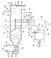
(第1実施形態)
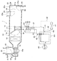
図1に、本実施形態における車両用空調装置の全体構成を示し、図2に、この車両用空調装置の電気制御部の構成を示す。本実施形態の車両用空調装置は、エンジン(内燃機関)EGおよび走行用電動モータから車両走行用の駆動力を得るハイブリッド車に搭載されるものである。したがって、エンジンEGが本発明の車両走行用の駆動力を得るための駆動手段に相当する。
(First embodiment)
FIG. 1 shows an overall configuration of a vehicle air conditioner according to the present embodiment, and FIG. 2 shows a configuration of an electric control unit of the vehicle air conditioner. The vehicle air conditioner of the present embodiment is mounted on a hybrid vehicle that obtains driving force for vehicle traveling from an engine (internal combustion engine) EG and a traveling electric motor. Therefore, the engine EG corresponds to a driving means for obtaining a driving force for traveling the vehicle according to the present invention.
本実施形態のハイブリッド車両は、車両の走行負荷に応じてエンジンEGを作動あるいは停止させて、エンジンEGおよび走行用電動モータの双方から駆動力を得て走行する走行状態や、エンジンを停止させて走行用電動モータのみから駆動力を得て走行する走行状態等を切り替えることができる。これにより、車両走行用の駆動力をエンジンEGのみから得る通常の車両に対して車両燃費を向上させている。 The hybrid vehicle according to this embodiment operates or stops the engine EG according to the travel load of the vehicle, obtains driving force from both the engine EG and the travel electric motor, and stops the engine. It is possible to switch a traveling state in which traveling is performed by obtaining a driving force only from the traveling electric motor. Thereby, the vehicle fuel consumption is improved with respect to the normal vehicle which obtains the driving force for vehicle travel only from the engine EG.
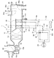
車両用空調装置1は、図1に示す室内空調ユニット10と、制御手段としての図2に示す空調制御装置60とを備えている。
The
室内空調ユニット10は、車室内最前部の計器盤(インストルメントパネル)の内側に配置されて、その外殻を形成するケーシング11内に送風機12、蒸発器13、第1ヒータコア14、第2ヒータコア15等を収容したものである。
The indoor
ケーシング11は、車室内に送風される送風空気の空気通路を形成しており、ある程度の弾性を有し、強度的にも優れた樹脂で成形されている。ケーシング11内の送風空気流れ最上流側には、内気(車室内空気)と外気(車室外空気)とを切替導入する内外気切替箱20が配置されている。
The
より具体的には、内外気切替箱20には、ケーシング11内に内気を導入させる内気導入口21および外気を導入させる外気導入口22が形成されている。さらに、内外気切替箱20の内部には、内気の風量と外気の風量との風量割合を変化させる内外気切替ドア23が配置されている。外気切替ドア23は、内外気切替ドア用の電動アクチュエータ71によって駆動され、この電動アクチュエータ71は、空調制御装置60から出力される制御信号によって、その作動が制御される。
More specifically, the inside / outside
内外気切替箱20の空気流れ下流側には、内外気切替箱20を介して吸入した空気を車室内へ向けて送風する送風機(ブロワ)12が配置されている。この送風機12は、遠心多翼ファン12aを電動モータ12bにて駆動する電動送風機であって、空調制御装置60から出力される制御信号によって回転数(送風量)が制御される。
A
送風機12の空気流れ下流側には、蒸発器13が配置されている。蒸発器13は、その内部を流通する冷媒と送風空気とを熱交換させて送風空気を冷却する冷却用熱交換器である。蒸発器13は、図示しない圧縮機、凝縮器、気液分離器、膨張弁等とともに、冷凍サイクルを構成している。
An
蒸発器13の空気流れ下流側には、蒸発器13通過後の空気を流す加熱用冷風通路16、加熱冷風バイパス通路17といった空気通路、並びに、加熱用冷風通路16および加熱冷風バイパス通路17から流出した空気を混合させる混合空間18が形成されている。
On the downstream side of the air flow of the
加熱用冷風通路16には、蒸発器13通過後の空気を加熱するための加熱手段としての第1、第2ヒータコア14、15が配置されている。第1ヒータコア14は、エンジンEGの冷却水と蒸発器13通過後の空気とを熱交換させて、蒸発器13通過後の空気を加熱する第1加熱用熱交換器である。第2ヒータコア15は、第1ヒータコア14の空気流れ下流側に配置されており、エンジンEGの冷却水と第1ヒータコア14通過後の空気とを熱交換させて、第1ヒータコア14通過後の空気を加熱する第2加熱用熱交換器である。ちなみに、冷却水は、水もしくは添加成分を含む水である。
First and
車両用空調装置1は、第1、第2ヒータコア14、15とエンジンEGとの間を冷却水が循環する冷却水回路30を有している。この冷却水回路30には、第1、第2ヒータコア14、15用の冷却水流路31と、ラジエータ41用の冷却水流路32とが並列して設けられている。
The
第1、第2ヒータコア14、15用の冷却水流路31は、分岐点31aと合流点31bを有し、エンジンEGから流出した冷却水が、分岐点31aで分岐して第1ヒータコア14に向かって流れる第1ヒータコア14用の冷却水流路33と、第2ヒータコア15に向かって流れる第2ヒータコア用の冷却水流路34とを有している。合流点31bで、第1、第2ヒータコア14、15をそれぞれ通過した冷却水が合流する。このように、第1、第2ヒータコア14、15は、冷却水流れに対して並列に配置されている。
The cooling
第2ヒータコア用の冷却水流路34においては、第2ヒータコア15よりも冷却水流れの下流側に吸熱部としての吸熱側熱交換器51が設けられ、第2ヒータコア15よりも冷却水流れの上流側に放熱部としての放熱側熱交換器52が設けられている。さらに、第2ヒータコア用の冷却水流路34の外側において、吸熱側熱交換器51と放熱側熱交換器52との間にペルチェ素子53が設けられている。
In the cooling
吸熱側熱交換器51は、冷却水から吸熱するための熱交換器であり、放熱側熱交換器52は、冷却水に放熱するための熱交換器である。吸熱側熱交換器51の内部を流れる冷却水の向きと、放熱側熱交換器52の内部を流れる冷却水の向きは正反対であり、冷却水が対向して流れるようになっている。
The heat absorption
ペルチェ素子53は、吸熱側熱交換器51と熱的に接続された吸熱面と放熱側熱交換器52と熱的に接続された放熱面とを有し、直流電流が流れることで、吸熱面が吸熱するとともに放熱面が放熱するものである。すなわち、ペルチェ素子53は、吸熱面側から放熱面側へ熱を汲み上げる汲上手段である。この汲み上げられる熱量は、電流量の大きさによって調整される。
The
なお、熱的に接続されたとは、熱が伝導する状態となっていることを意味する。したがって、ペルチェ素子53は、直流電流が流れると、吸熱側熱交換器51を介して、第2ヒータコア15流出側の冷却水から吸熱し、放熱側熱交換器52を介して、第2ヒータコア15流入側の冷却水に放熱するようになっている。このペルチェ素子53は、空調制御装置60から出力される制御信号によって、電源のON、OFFや、ON時の電流量等が制御される。
Note that “thermally connected” means that heat is conducted. Accordingly, when a direct current flows, the
エンジンEGの冷却水入口側には、サーモスタット42が設けられており、このサーモスタット42によって、第1、第2ヒータコア14、15用の冷却水流路31と、ラジエータ41用の冷却水流路32とを流れる冷却水の流量が調整される。また、冷却水回路30には、冷却水流れを形成する電動式のウォータポンプ43が設けられている。このウォータポンプ43は、エンジンEGの停止時であっても、空調制御装置60による制御によって作動する。なお、ウォータポンプ43は、エンジンEGからの動力を受けて作動するものであっても良く、この場合、エンジンEGの停止と共にウォータポンプ43も停止する。
A
エンジンEGの冷却水出口付近には、エンジンEGから流出した冷却水の温度を検出する第1冷却水温度センサ65が設けられている。また、冷却水回路30の放熱側熱交換器52と第2ヒータコア15との間に、第2ヒータコア15に流入する冷却水の温度を検出する第2冷却水温度センサ66が設けられている。
Near the cooling water outlet of the engine EG, a first cooling
一方、加熱冷風バイパス通路17は、蒸発器13通過後の空気を、ヒータコア14を通過させることなく、混合空間18に導くための空気通路である。したがって、混合空間18にて混合された送風空気の温度は、加熱用冷風通路16を通過する空気および加熱冷風バイパス通路17を通過する空気の風量割合によって変化する。
On the other hand, the heating / cooling
そこで、本実施形態では、蒸発器13の空気流れ下流側であって、加熱用冷風通路16および加熱冷風バイパス通路17の入口側に、加熱用冷風通路16および加熱冷風バイパス通路17へ流入させる冷風の風量割合を連続的に変化させるエアミックスドア19を配置している。
Therefore, in the present embodiment, the cool air that flows into the heating
したがって、エアミックスドア19は、混合空間18内の空気温度(車室内へ送風される送風空気の温度)を調整する温度調整手段を構成する。エアミックスドア19は、エアミックスドア用の電動アクチュエータ72によって駆動され、この電動アクチュエータ72は、空調制御装置60から出力される制御信号によって、その作動が制御される。
Therefore, the
さらに、ケーシング11の送風空気流れ最下流部には、混合空間18から空調対象空間である車室内へ温度調整された送風空気を吹き出すために、デフロスタ開口部24、フェイス開口部25およびフット開口部26が設けられている。
Furthermore, in order to blow out the blown air whose temperature is adjusted from the
デフロスタ開口部24には、図示しないデフロスタダクトが接続され、このデフロスタダクト先端部のデフロスタ吹出口から車両前面窓ガラスの内面に向けて空調風を吹き出すようになっている。フェイス開口部25には、図示しないフェイスダクトが接続され、フェイスダクト先端部のフェイス吹出口から車室内の乗員の上半身に向けて空調風を吹き出すようになっている。また、フット開口部26には、図示しないフットダクトが接続され、フットダクト先端部のフット吹出口から乗員の足元に向けて空調風を吹き出すようになっている。
A defroster duct (not shown) is connected to the
また、ケーシング11には、吹出口モードを切り替えるための吹出口モードドアとして、フロスタ開口部24を開閉するデフロスタドア24aと、フェイス開口部25を開閉するフェイスドア25aと、フット開口部26を開閉するフットドア26aとが設けられている。これらの吹出口モードドア24a、25a、26aは、吹出口モードドア用の電動アクチュエータ73によって駆動され、この電動アクチュエータ73は、空調制御装置60から出力される制御信号によって、その作動が制御される。
The
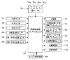
次に、図2により、本実施形態の電気制御部について説明する。空調制御装置60は、CPU、ROMおよびRAM等を含む周知のマイクロコンピュータとその周辺回路から構成され、そのROM内に記憶された空調制御プログラムに基づいて各種演算、処理を行い、出力側に接続された送風機12、各種電動アクチュエータ71、72、73、ペルチェ素子53等の作動を制御する。
Next, the electric control unit of the present embodiment will be described with reference to FIG. The air
また、空調制御装置60の入力側には、車室内温度Trを検出する内気センサ61、外気温Tamを検出する外気センサ62(外気温検出手段)、車室内の日射量Tsを検出する日射センサ63、蒸発器13から吹き出される空気温度である蒸発器吹出空気温度(蒸発器温度)TEを検出する蒸発器温度センサ64(蒸発器温度検出手段)、エンジン冷却水温度TWを検出する第1、第2冷却水温度センサ65、66(冷却水温度検出手段)等のセンサ群の検出信号が入力される。
Further, on the input side of the air-
さらに、空調制御装置60の入力側には、車室内前部の計器盤付近に配置された操作パネル70に設けられた各種空調操作スイッチからの操作信号が入力される。操作パネル70に設けられた各種空調操作スイッチとしては、具体的に、車両用空調装置1の作動スイッチ(図示せず)、エアコンのオン・オフを切り替えるエアコンスイッチ70a、車両用空調装置1の自動制御を設定・解除するオートスイッチ70b、運転モードの切替スイッチ(図示せず)、吸込口モードを切り替える吸込口モードスイッチ(図示せず)、吹出口モードを切り替える吹出口モードスイッチ(図示せず)、送風機12の風量設定スイッチ(図示せず)、車室内温度を設定する車室内温度設定スイッチ70c、冷凍サイクルの省動力化を優先させる指令を出力するエコノミースイッチ70d等が設けられている。
Further, on the input side of the air
さらに、空調制御装置60は、エンジンEGの作動を制御するエンジン制御装置80に電気的接続されており、空調制御装置60およびエンジン制御装置80は互いに電気的に通信可能に構成されている。これにより、一方の制御装置に入力された検出信号あるいは操作信号に基づいて、他方の制御装置が出力側に接続された各種機器の作動を制御することもできる。例えば、空調制御装置60がエンジン制御装置80へエンジンEGの作動要求信号を出力することによって、エンジンEGを作動させることができる。
Further, the air
次に、図3により、上記構成における本実施形態の作動を説明する。図3は、空調制御装置60の制御処理を示すフローチャートである。なお、図3中の各ステップは、空調制御装置60が有する各種の機能実現手段を構成している。
Next, the operation of this embodiment in the above configuration will be described with reference to FIG. FIG. 3 is a flowchart showing a control process of the air
まず、ステップS1では、フラグ、タイマ等の初期化、および上述した電動アクチュエータを構成するステッピングモータの初期位置合わせ等が行われる。 First, in step S1, initialization of a flag, a timer, and the like, initial alignment of a stepping motor constituting the electric actuator described above, and the like are performed.
次のステップS2では、操作パネル70の操作信号や、空調制御に用いられる車両環境状態の信号、すなわち上述のセンサ群61〜66等の検出信号を読み込んでステップS3へ進む。具体的な操作信号としては、車室内温度設定スイッチ70cによって設定される車室内設定温度Tset、吹出口モードの選択信号、吸込口モードの選択信号、送風機12の風量の設定信号等がある。
In the next step S2, an operation signal of the
ステップS3では、車室内吹出空気の目標吹出空気温度TAOを算出する。目標吹出空気温度TAOは、空調熱負荷、すなわち、車室内設定温度と、車室内温度等の車両環境条件とに基づいて算出され、具体的には、下記数式F1により算出される。
TAO=Kset×Tset−Kr×Tr−Kam×Tam−Ks×Ts+C…(F1)
ここで、Tsetは車室内温度設定スイッチ70cによって設定された車室内設定温度、Trは内気センサ61によって検出された車室内温度(内気温)、Tamは外気センサ62によって検出された外気温、Tsは日射センサ63によって検出された日射量である。Kset、Kr、Kam、Ksは制御ゲインであり、Cは補正用の定数である。
In step S3, a target blown air temperature TAO of the vehicle compartment blown air is calculated. The target blown air temperature TAO is calculated based on the air-conditioning heat load, that is, the vehicle interior set temperature and the vehicle environmental conditions such as the vehicle interior temperature, and specifically, is calculated by the following formula F1.
TAO = Kset × Tset−Kr × Tr−Kam × Tam−Ks × Ts + C (F1)
Here, Tset is the vehicle interior set temperature set by the vehicle interior
続くステップS4では、空調制御装置60に接続された各種機器の制御目標値、例えば、送風機12の送風量(ブロワレベル)、吸込口モード、吹出口モード、エアミックスドアの開度、エンジン作動要求の要否、ペルチェ素子53のON/OFF等を決定する。送風量、吹出口モード等については、目標吹出空気温度TAOに基づいて決定する。エンジン作動要求の要否については、第1冷却水温度センサ65で検出した冷却水温度TW1が所定の基準温度(エンジン作動の要求水温)よりも低い場合に、エンジン作動要求信号の出力を決定する。なお、ペルチェ素子53のON/OFFの決定については後述する。
In subsequent step S4, control target values of various devices connected to the air
その後、ステップS5では、ステップS4で決定された制御目標値が得られるように、空調制御装置60に接続された各種機器やエンジン制御装置80に対して制御信号を出力する。
Thereafter, in step S5, a control signal is output to various devices connected to the air
これにより、送風機12が所望の送風量となるように作動し、所望の吹出口モードとなるように、吹出口モードドアが所定の位置となり、必要に応じてエンジンEGが作動する。
Thereby, the
続く、ステップS6では、制御周期τの間待機し、制御周期τの経過を判定するとステップS2に戻るようになっている。 In step S6, the process waits for the control period τ, and returns to step S2 when it is determined that the control period τ has elapsed.
次に、上述したステップS4での制御目標値の決定処理のうちペルチェ素子53のON/OFFの決定処理を説明する。図4に、ペルチェ素子53のON/OFFの決定処理を説明するためのフローチャートを示す。
Next, the ON / OFF determination process of the
ステップS11では、第2ヒータコア吹出空気温度TWDを算出する。第2ヒータコア吹出空気温度TWDは、第2ヒータコア15からの吹出空気温度であり、第2ヒータコア15で冷却水との熱交換によって空気が加熱されたときの加熱空気温度である。このヒータコア吹出空気温度TWDは、厳密には、第2冷却水温度センサ66で検出した冷却水温度TW2、蒸発器13の通過後の空気温度TE、第2ヒータコア15の熱交換性能等に基づいて算出されるが、冷却水温度TW2と略同一である。
In step S11, the second heater core blown air temperature TWD is calculated. The second heater core blown air temperature TWD is the blown air temperature from the
続く、ステップS12では、第2ヒータコア吹出空気温度TWDと目標吹出空気温度TAOを比較し、TWDがTAOよりも低いか否かを判定する。TWDがTAOよりも低ければ、YES判定して、ステップS13に進み、ペルチェ素子53を通電(ON)状態とする。一方、TWDがTAO以上であれば、NO判定して、ステップS14に進み、ペルチェ素子53を非通電(OFF)状態とする。
In step S12, the second heater core blown air temperature TWD is compared with the target blown air temperature TAO to determine whether TWD is lower than TAO. If TWD is lower than TAO, a YES determination is made, the process proceeds to step S13, and the
したがって、エンジンEGの停止後から長時間経過して、エンジンEGの作動時よりも冷却水温度が低下した場合、TWDがTAOよりも低くなる。そこで、このような場合に、本実施形態では、ペルチェ素子53を通電し、第2ヒータコア15を通過した後の冷却水から吸熱して、第2ヒータコア15に向かう冷却水に放熱させる。これにより、第2ヒータコア15に流入する冷却水温度を上昇させて、冷却水の温度を暖房に必要な温度にすることができる。なお、この場合、空調制御装置60は、エアミックスドア19を最大暖房位置とすることが好ましい。
Therefore, when a long time elapses after the engine EG is stopped and the cooling water temperature is lower than when the engine EG is operating, the TWD becomes lower than the TAO. In such a case, in this embodiment, the
一方、エンジンEGの作動時や、エンジンEGの停止後からの経過時間が短く、冷却水温度がエンジンEGの作動時に近い場合のように、冷却水の温度が十分に高く、TWDがTAO以上となる場合であれば、ペルチェ素子53による冷却水の加熱が不要なので、空調制御装置60はペルチェ素子53を非通電とする。この場合、空調制御装置60は、従来と同様に、エアミックスドア19の位置(開度)を制御することによって、空調風の温度を調整する。
On the other hand, when the engine EG is operating or when the elapsed time from when the engine EG is stopped is short and the cooling water temperature is close to when the engine EG is operating, the temperature of the cooling water is sufficiently high, and the TWD is greater than or equal to TAO. If this is the case, since the cooling water heating by the
次に、本実施形態の主な効果について説明する。 Next, main effects of this embodiment will be described.
(1)本実施形態によれば、エンジンEGの作動の代わりに、ペルチェ素子53の作動によって、第2ヒータコア15に流入する冷却水の温度を上昇させるようになっているので、ペルチェ素子53を備えていない場合と比較して、エンジンEGの作動頻度を低減でき、エンジンEGの燃費を向上させることができる。
(1) According to the present embodiment, the temperature of the cooling water flowing into the
また、ペルチェ素子53によって冷却水の温度を上昇させているので、ペルチェ素子53を備えていない場合と比較して、エンジンEGの停止直後からの冷却水の温度低下を遅くでき、冷却水温度TW1がエンジン作動の要求水温より低くなるまでの時間を長くすることができる。よって、このことからも、本実施形態によれば、ペルチェ素子53を備えていない場合と比較して、エンジンEGの作動頻度を低減できると言える。
Further, since the temperature of the cooling water is raised by the
(2)ところで、第2ヒータコア15に流入する冷却水の温度は、暖房の熱源として必要な温度、例えば、60℃以上であることが望まれる。一方、エンジンEGの内部を流れる冷却水の温度は、エンジンEGの各部が暖まってエンジンEGが良好に作動する下限温度以上、例えば、40℃以上であることが望まれる。
(2) By the way, it is desirable that the temperature of the cooling water flowing into the
このため、ペルチェ素子53を有していない従来の車両用空調装置では、暖房の熱源を確保するため、冷却水温度が60℃以上となるように、エンジン作動の要求水温を例えば60℃付近に設定する必要があった。
For this reason, in the conventional vehicle air conditioner which does not have the
これに対して、本実施形態によれば、エンジンEGの停止時に、冷却水の温度が60℃を下回っても、ペルチェ素子53を作動させて、冷却水の温度を上昇させることができるので、エンジン作動の要求水温を従来よりも低い温度、例えば40℃付近に設定することができる。
On the other hand, according to the present embodiment, when the engine EG is stopped, the temperature of the cooling water can be increased by operating the
ちなみに、この要求水温の設定については、ペルチェ素子53の作動によっても、暖房に必要な温度に維持できなくなる場合や、エンジンEGが良好に作動する温度を維持できなくなる場合に、エンジンが作動するように、エンジン作動の要求水温を設定すれば良い。
By the way, regarding the setting of the required water temperature, the engine operates when the temperature required for heating cannot be maintained even when the
(3)本実施形態では、ペルチェ素子53が空気ではなく、エンジンEGの冷却水から吸熱している。
(3) In the present embodiment, the
ここで、ペルチェ素子53の吸熱対象を、エンジンEGの冷却水の代わりに、外気とすることもできる。しかし、ヒータコアによる送風空気の加熱能力を確保するために、エンジン冷却水を所望温度まで上昇させようとする場合、外気温が低いほど、ペルチェ素子53に要求される熱の汲上能力が大きくなり、ペルチェ素子53の消費電力が大きくなってしまう。
Here, the heat absorption target of the
これに対して、本実施形態によれば、冬場の外気温よりも温度が高いエンジンEGの冷却水から吸熱しているので、外気から吸熱する場合と比較して、ペルチェ素子53から冷却水への放熱量を多くできる。この結果、冷却水を所望温度まで上昇させるためのペルチェ素子53の消費電力を低減できる。
On the other hand, according to the present embodiment, heat is absorbed from the cooling water of the engine EG whose temperature is higher than the outside air temperature in winter. Therefore, compared to the case where heat is absorbed from the outside air, the
ちなみに、空調制御装置60は、冷却水温度TW1がエンジン作動の要求水温よりも低い場合にエンジン作動を要求するようになっており、本実施形態では、少なくとも冷却水温度を40℃以上としているので、常に、冷却水温度は外気温よりも高くなっている。
Incidentally, the air
(4)ペルチェ素子53を有していない従来の車両用空調装置では、第2ヒータコア15から流出した冷却水がそのままエンジンEGに流入するので、第2ヒータコア15で送風空気と熱交換されなかった熱量が、エンジンEGの表面から放出されていた。
(4) In the conventional vehicle air conditioner that does not have the
これに対して、本実施形態では、ペルチェ素子53によって、第2ヒータコア15から流出した冷却水から熱を汲み上げているので、第2ヒータコア15で送風空気と熱交換されなかった熱量をさらに暖房に利用することができ、従来よりも冷却水の熱量を有効に利用できる。
On the other hand, in the present embodiment, heat is pumped up from the cooling water flowing out from the
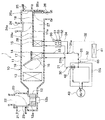
(第2実施形態)
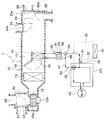
図5に、本実施形態における車両用空調装置の全体構成を示す。
(Second Embodiment)
In FIG. 5, the whole structure of the vehicle air conditioner in this embodiment is shown.
本実施形態の冷却水回路30は、第2ヒータコア用の冷却水流路34において、放熱側熱交換器52に流入する前の冷却水の一部を吸熱側熱交換器51に導く第1バイパス流路35と、第1バイパス流路35に流れる冷却水の流量を調整する第1流量調整バルブ36とを有している。
In the
第1バイパス流路35は、一端が放熱側熱交換器52の上流側に連なり、他端が第2ヒータコア15と吸熱側熱交換器51との間に連なっている。このため、この第1バイパス流路35を流れる冷却水は、放熱側熱交換器52と第2ヒータコア15を迂回して、放熱側熱交換器52で放熱しないとともに第2ヒータコア15で空気と熱交換せずに、吸熱側熱交換器51に流入する。
One end of the
第1流量調整バルブ36は、放熱側熱交換器52に向かって冷却水が流れる冷却水流路と第1バイパス流路35との分岐点に配置されている。この流量調整バルブ36は、放熱側熱交換器52に向かって流れる冷却水の流量と、第1バイパス流路35を流れる冷却水の流量とを調整するものである。なお、第1流量調整バルブ36は、第1バイパス流路35の途中に配置されていても良い。
The first flow
本実施形態では、空調制御装置60は、ペルチェ素子53の通電時に、第1バイパス流路35に冷却水の一部が流れ、ペルチェ素子53の非通電時に、第1バイパス流路35の冷却水流量が0となるように、第1流量調整バルブ36を制御する。
In the present embodiment, the air-
これにより、ペルチェ素子53の通電時では、放熱側熱交換器52に流入する前の冷却水の一部が吸熱側熱交換器51に導かれるので、放熱側熱交換器52に流入する冷却水の温度と、吸熱側熱交換器51に流入する冷却水の温度とを近づけることができる。ここで、ペルチェ素子53は、吸熱面と放熱面との温度差が小さいほど、放熱量が多いことが知られている。したがって、本実施形態によれば、第1バイパス流路35を有していない場合と比較して、放熱側熱交換器52で冷却水に放熱される放熱量を多くでき、第2ヒータコア15に流入する冷却水の温度上昇を大きくできる。
Thereby, when the
また、本実施形態では、ペルチェ素子53の通電時に、空調制御装置60は、第1流量調整バルブ36を制御して、第2ヒータコア15に要求される暖房能力に応じて、第1バイパス流路35の冷却水流量を調整する。
Further, in the present embodiment, when the
例えば、吹出口からの吹出風量が少ないときのように、第2ヒータコア15に要求される暖房能力が小さい場合、第1バイパス流路35を流れる冷却水の流量を、加熱側熱交換器52を流れる冷却水の流量よりも多くする。この場合、第2ヒータコア15を流れる冷却水の流量を少なくしているので、放熱側熱交換器52での放熱による冷却水の温度上昇が大きくなる。
For example, when the heating capacity required for the
また、吹出口からの吹出風量が多いときのように、第2ヒータコア15に要求される暖房能力が大きい場合、第1バイパス流路35を流れる冷却水の流量を、加熱側熱交換器52を流れる冷却水の流量よりも少なくする。このように、加熱側熱交換器52を流れる冷却水の流量を多くすることで、第2ヒータコア15の暖房能力を大きくできる。
Further, when the heating capacity required for the
なお、本実施形態では、第1流量調整バルブ36を用いたが、第1流量調整バルブ36の代わりに、第1バイパス流路35の冷却水流量を0より多い所定量と0との間で切り替える流量切替バルブを用いても良い。
In the present embodiment, the first flow
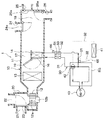
(第3実施形態)
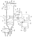
図6に本実施形態における車両用空調装置の全体構成を示す。
(Third embodiment)
FIG. 6 shows the overall configuration of the vehicle air conditioner in the present embodiment.
本実施形態の車両用空調装置1は、第2ヒータコア15から吹き出される温風をフット開口部26のみに導くフット専用通路27を有している。このフット専用通路27は、ケーシング11の内部のうち、第2ヒータコア15の空気流れ下流側の空間をフット開口部26側の空間と他の開口部24、25側の空間とに仕切る仕切壁11aによって形成されている。
The
また、仕切壁11aの第2ヒータコア15の直後には、開口部28とこの開口部28を開閉する開閉ドア28aが設けられている。この開閉ドア28aが開口部28を開くことで、第2ヒータコア15から吹き出される温風をデフロスタ開口部24、フェイス開口部25およびフット開口部26のいずれにも導くことができる。一方、開閉ドア28aが開口部28を閉じることで、第2ヒータコア15から吹き出される温風をフット開口部26のみに導くようになっている。
An
また、第1ヒータコア14の方が第2ヒータコア15よりも体格が大きく、開閉ドア28aが開口部28を閉じた場合、第1ヒータコ14から吹き出される温風の一部が、第2ヒータコア15を通過せず、デフロスタ開口部24、フェイス開口部25に流れるようになっている。
Further, when the
本実施形態では、ペルチェ素子53の通電時において、空調制御装置60が、開閉ドア28aを閉じる制御を行う。これにより、例えば、フット吹出口とサイドフェイス吹出口とから空調風が吹き出されるフットモード時では、フット吹出口から第1、第2ヒータコア14、15で加熱された空気を吹き出し、サイドフェイス吹出口から第1ヒータコア14で加熱された空気を吹き出すので、頭寒足熱の空調を実施でき、乗員の快適性を向上できる。
In the present embodiment, when the
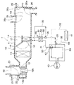
(第4実施形態)
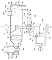
図7に本実施形態における車両用空調装置の全体構成を示す。
(Fourth embodiment)
FIG. 7 shows the overall configuration of the vehicle air conditioner in the present embodiment.
第1実施形態では、第1、第2ヒータコア14、15が冷却水流れに対して並列に配置されていたのに対して、本実施形態では、第1、第2ヒータコア14、15が冷却水流れに対して直列に配置されている。
In the first embodiment, the first and
具体的には、冷却水回路30において、第1、第2ヒータコア用の冷却水流路31は、1つの流路となっており、エンジンEGの冷却水出口から流出した冷却水が、第1ヒータコア14を流れた後、第2ヒータコア15を流れ、エンジンEGの冷却水入口に流入するようになっている。このように、第1ヒータコア14が冷却水流れの上流側に配置され、第2ヒータコア15が冷却水流れの下流側に配置されている。
Specifically, in the
吸熱側熱交換器51は、第2ヒータコア15よりも冷却水流れの下流側に配置されており、加熱側熱交換器52は、第1ヒータコア14よりも冷却水流れの下流側であって、第2ヒータコア15よりも冷却水流れの上流側に配置されている。
The heat absorption
本実施形態においても、ペルチェ素子53によって、吸熱側熱交換器51を介して、第2ヒータコア15で空気と熱交換した後の冷却水から吸熱し、放熱側熱交換器52を介して、第2ヒータコア15に流入する冷却水に放熱するので、第1実施形態と同様の効果を奏する。
Also in the present embodiment, the
ただし、本実施形態では、第1ヒータコア14で空気と熱交換した後の冷却水が、放熱側熱交換器52に流入するので、第1、第2ヒータコア14、15が冷却水流れに対して並列に配置されている第1実施形態と比較して、放熱側熱交換器52に流入する冷却水の温度が低くなり、第2ヒータコアの暖房能力が低下してしまう。このため、本実施形態よりも第1実施形態の方が好ましい。
However, in this embodiment, the cooling water after heat exchange with the air in the
(第5実施形態)
図8に本実施形態における車両用空調装置の全体構成を示す。
(Fifth embodiment)
FIG. 8 shows the overall configuration of the vehicle air conditioner in the present embodiment.
第1〜第4実施形態の車両用空調装置1は、第1、第2ヒータコア14、15の2つのヒータコアを有していたが、本実施形態の車両用空調装置1は、1つのヒータコア14を有している。
Although the
車両用空調装置1は、ヒータコア14とエンジンEGとの間を冷却水が循環する冷却水回路30を有している。この冷却水回路30には、ヒータコア14用の冷却水流路31と、ラジエータ41用の冷却水流路32とが並列して設けられている。
The
ヒータコア14用の冷却水流路31においては、ヒータコア14よりも冷却水流れの下流側に吸熱部としての吸熱側熱交換器51が設けられ、ヒータコア14よりも冷却水流れの上流側に放熱部としての放熱側熱交換器52が設けられている。
In the cooling
本実施形態においても、ペルチェ素子53によって、吸熱側熱交換器51を介して、ヒータコア14で空気と熱交換した後の冷却水から吸熱し、放熱側熱交換器52を介して、ヒータコア14に流入する冷却水に放熱するので、第1実施形態と同様の効果を奏する。
Also in the present embodiment, the
(第6実施形態)
図9に本実施形態における車両用空調装置の全体構成を示す。本実施形態は、第2実施形態と第5実施形態とを組み合わせたものである。
(Sixth embodiment)
FIG. 9 shows the overall configuration of the vehicle air conditioner in the present embodiment. The present embodiment is a combination of the second embodiment and the fifth embodiment.
本実施形態では、図8に示す冷却水回路30に対して、放熱側熱交換器52に流入する前の冷却水の一部を吸熱側熱交換器51に導く第1バイパス流路35と、第1バイパス流路35に流れる冷却水の流量を調整する流量調整バルブ36とを設けている。この流量調整バルブ36は、第2実施形態と同様に空調制御装置60によって制御される。したがって、本実施形態においても、第2、第5実施形態と同様の効果を奏する。
In the present embodiment, with respect to the
(第7実施形態)
図10に本実施形態における車両用空調装置の全体構成を示す。
(Seventh embodiment)
FIG. 10 shows the overall configuration of the vehicle air conditioner in the present embodiment.
本実施形態では、図8に示す冷却水回路30に対して、放熱側熱交換器52に流入する前の冷却水と、吸熱側熱交換器51に流入する前の冷却水との間で熱交換させる熱交換器37を設けている。
In the present embodiment, the cooling
具体的には、熱交換器37の内部に、放熱側熱交換器52の冷却水流れ上流側の冷却水が流れるとともに、第2ヒータコア15から流出した冷却水が流れるようになっており、両方の冷却水の間で熱交換がされる。そして、第2ヒータコア15から流出した冷却水は、熱交換器37で熱交換して温度が上昇した後に、吸熱側熱交換器51に流入するようになっている。
Specifically, inside the
これにより、放熱側熱交換器52に流入する冷却水の温度と、吸熱側熱交換器51に流入する冷却水の温度とを近づけることができる。ここで、ペルチェ素子53は、吸熱面と放熱面との温度差が小さいほど、放熱量が多いことが知られている。したがって、本実施形態によれば、熱交換器37を有していない場合と比較して、放熱側熱交換器52で冷却水に放熱される放熱量を多くでき、ヒータコア14に流入する冷却水の温度上昇を大きくできる。
Thereby, the temperature of the cooling water flowing into the heat radiation
(第8実施形態)
図11に本実施形態における車両用空調装置の全体構成を示す。
(Eighth embodiment)
FIG. 11 shows the overall configuration of the vehicle air conditioner in the present embodiment.
本実施形態では、図8に示す冷却水回路30に対して、放熱側熱交換器52よりも上流側の冷却水の一部を、エンジンEGの冷却水入口に導く第2バイパス流路38と、第2バイパス流路38を流れる冷却水の流量を調整する第2流量調整バルブ39とを設けている。
In the present embodiment, with respect to the
この第2バイパス流路38は、一端がエンジンEGの冷却水入口の下流側であって放熱側熱交換器52の上流側の冷却水流路に連なり、他端が吸熱側熱交換器51の下流側であってエンジンEGの冷却水出口の上流側に連なっている。このため、この第2バイパス流路38を流れる冷却水は、放熱側熱交換器52、ヒータコア14および吸熱側熱交換器51を迂回して、エンジンEGに流入する。
One end of the
第2流量調整バルブ39は、放熱側熱交換器52に向かって冷却水が流れる冷却水流路と第2バイパス流路38との分岐点に配置されている。第2流量調整バルブ39は、放熱側熱交換器52に向かって流れる冷却水の流量と、第2バイパス流路38を流れる冷却水の流量とを調整するものである。なお、第2流量調整バルブ39は、第2バイパス流路38の途中に配置されていても良い。
The second flow
本実施形態では、空調制御装置60は、ペルチェ素子53の通電時に、第2バイパス流路38に冷却水の一部が流れ、ペルチェ素子53の非通電時に、第2バイパス流路38の冷却水流量が0となるように、第2流量調整バルブ39を制御する。
In the present embodiment, the air-
ここで、図8に示す冷却水回路30のように、第2バイパス流路38を有していない場合、ペルチェ素子53が冷却水から吸熱すると、吸熱側熱交換器51から流出する冷却水の温度が低くなるので、エンジンEGの冷却水入口に流入する冷却水と、エンジンEGの冷却水出口から流出する冷却水の温度差が大きくなる恐れがある。この場合、エンジンEGにおける冷却水の入口側部位と出口側部位との間での温度差によって、エンジンEGに熱歪みが生じ、エンジンEGの破損につながってしまう。
Here, as in the
これに対して、本実施形態によれば、ペルチェ素子53の通電時に、放熱側熱交換器52よりも上流側の冷却水の一部を、エンジンEGの冷却水入口に導くので、エンジンEGの冷却水入口に流入する冷却水と、エンジンEGの冷却水出口から流出する冷却水との温度差を低減でき、エンジンEGの熱歪みの発生を抑制できる。
On the other hand, according to the present embodiment, when the
なお、エンジンEGの冷却水入口に流入する冷却水と、エンジンEGの冷却水出口から流出する冷却水との温度差を低減するという観点より、第2バイパス流路38に冷却水の一部を流す場合では、放熱側熱交換器52に向かって流れる冷却水の流量よりも、第2バイパス流路38を流れる冷却水の流量を多くすることが望ましい。
From the viewpoint of reducing the temperature difference between the cooling water flowing into the cooling water inlet of the engine EG and the cooling water flowing out of the cooling water outlet of the engine EG, a part of the cooling water is put into the
また、本実施形態では、第2流量調整バルブ39を用いたが、第2流量調整バルブ39の代わりに、第2バイパス流路38の冷却水流量を0より多い所定量と0との間で切り替える流量切替バルブを用いても良い。
In the present embodiment, the second flow
(第9実施形態)
図12に本実施形態における車両用空調装置の全体構成を示す。
(Ninth embodiment)
FIG. 12 shows the overall configuration of the vehicle air conditioner in the present embodiment.
本実施形態では、ヒータコア用の冷却水流路31に対して、ヒータコア14を迂回させる第3バイパス流路54と、この第3バイパス流路54を流れる冷却水の流量を調整する第3流量調整バルブ55とを設けている。
In the present embodiment, a third
ヒータコア用の冷却水流路31には、エンジンEGの冷却水出口からヒータコア14に向かって冷却水が流れ、ヒータコア14から流出した冷却水がエンジンEGの冷却水入口に向かって冷却水が流れる。第3流量調整バルブ55は、ヒータコア用の冷却水流路31と第3バイパス流路54との分岐点に配置されている。
In the cooling
そして、吸熱側熱交換器51は、ヒータコア14の冷却水流れ下流側ではなく、第3バイパス流路54の途中に吸熱側熱交換器51が配置されている。このため、吸熱側熱交換器51は、ヒータコア14で空気と熱交換した後の冷却水から吸熱するのではなく、エンジンEGの冷却水出口から流出した冷却水から吸熱する。
一方、放熱側熱交換器52は、ヒータコア用の冷却水流路31のうち第3流量調整バルブ55よりも冷却水流れの下流側であって、ヒータコア14の上流側に配置されている。
And the heat absorption
On the other hand, the heat radiation
空調制御装置60は、ペルチェ素子53の通電時では、吸熱側熱交換器51と放熱側熱交換器52の両方に冷却水が流れ、ペルチェ素子53の非通電時では、第3バイパス流路54を閉じてヒータコア14のみに冷却水が流れるように、第3流量調整バルブ55を制御するようになっている。
When the
このように、本実施形態では、ペルチェ素子53の通電時に、吸熱側熱交換器51と放熱側熱交換器52の両方に、エンジンEGの冷却水出口から流出した冷却水が流れることから、ペルチェ素子53の吸熱面と放熱面とが同じ温度となる。よって、本実施形態によれば、ペルチェ素子53による放熱量を多くすることができる。
As described above, in this embodiment, when the
(第10実施形態)
図13に本実施形態における車両用空調装置の全体構成を示す。
(10th Embodiment)
FIG. 13 shows the overall configuration of the vehicle air conditioner in the present embodiment.
本実施形態の車両用空調装置1は、エンジン用冷却水回路30とは別に、ヒータコア用温水回路90を有している。
The
エンジン用冷却水回路30は、エンジンEGの冷却水がエンジンEGとラジエータ41との間を循環する閉回路であり、冷却水流路31によって形成されている。
The
一方、ヒータコア用温水回路90は、エンジン用冷却水回路30とは独立した回路であって、ヒータコア14で送風空気を加熱するための加熱流体としての温水が循環する閉回路である。このヒータコア用温水回路90は、温水流路91によって形成されており、温水流路91の途中に温水流れを形成するウォータポンプ92が配置されている。
On the other hand, the heater core
そして、本実施形態では、吸熱側熱交換器51はエンジン用冷却水回路30に配置されており、エンジンEGの冷却水から吸熱するようになっている。一方、放熱側熱交換器52はヒータコア用温水回路90に配置されており、温水に放熱するようになっている。このため、ペルチェ素子53は、通電時に、吸熱側熱交換器51を介してエンジンEGの冷却水から吸熱して、放熱側熱交換器52を介してヒータコア14に流入する温水に放熱することで、温水を加熱するようになっている。したがって、本実施形態においても、ヒータコア14は、エンジンEGの冷却水を熱源として、送風空気を加熱していると言える。
In the present embodiment, the heat absorption
また、本実施形態では、冷却水回路30においては、第1冷却水温度センサが検出した冷却水温度TW1が要求水温よりも低下した場合に、空調制御装置60がエンジンEGの作動要求を行う。この要求水温は、エンジンEGが良好に作動できる下限温度、例えば、40℃付近に設定される。これにより、冷却水は、エンジンEGが良好に作動できる下限温度以上に維持される。
In the present embodiment, in the
一方、温水回路90においては、第2冷却水温度センサが検出した冷却水温度TW2が暖房に必要な温度以上、例えば、60℃以上となるように、空調制御装置60がペルチェ素子53の通電、非通電を制御するとともに、通電時の電流量を制御する。
On the other hand, in the
このように、本実施形態では、ペルチェ素子53によって、エンジンEGの冷却水からヒータコア14を流れる温水に熱を汲み上げることで、温水の温度を暖房に必要な温度以上とするので、エンジンEGの冷却水の温度を暖房に必要な温度以上にする必要がない。したがって、本実施形態によれば、エンジン作動の要求水温を従来よりも低い温度に設定できるので、エンジンEGの作動頻度を低減でき、エンジンEGの燃費を向上できる。
As described above, in the present embodiment, the temperature of the hot water is made higher than the temperature required for heating by pumping heat from the cooling water of the engine EG to the hot water flowing through the
また、本実施形態では、ペルチェ素子53が空気ではなく、エンジンEGの冷却水から吸熱しているので、本実施形態においても、第1実施形態で説明した(3)の効果を奏する。
Further, in this embodiment, since the
ところで、図8に示す冷却水回路30のように、ヒータコア14とエンジンEGとの間を冷却水が循環する場合では、ペルチェ素子53によって、ヒータコア14から流出の冷却水からヒータコア14に流入する冷却水へ熱を汲み上げたとき、ヒータコア14での送風空気との熱交換で余った熱が、吸熱側熱交換器51で全部吸収されずに、エンジンEGで放熱されてしまうという問題が考えられる。
By the way, when the cooling water circulates between the
これに対して、本実施形態によれば、エンジン用冷却水回路30と独立したヒータコア用温水回路90を採用しており、温水は閉じられたヒータコア用温水回路90のみを流れるので、ペルチェ素子53で汲み上げた熱量を全てヒータコア14で利用することができる。
On the other hand, according to the present embodiment, the heater core
なお、本実施形態では、ヒータコアが1つであったが、第1実施形態のように、2つのヒータコアを用いることもできる。例えば、ケーシング11の内部の空気流れ上流側に第1ヒータコアを配置し、その下流側に第2ヒータコアを配置する場合、第1ヒータコアにエンジンEGの冷却水が流れ、図13のヒータコア14のように、第2ヒータコアに温水回路90の温水が流れるようにする。このとき、冷却水回路30においては、第1ヒータコアを流れる冷却水路と、吸熱側熱交換器を流れる冷却水流路とを並列に設けることが好ましい。第1ヒータコアと吸熱側熱交換器との両方に温度が高い冷却水を流すことができるからである。
In this embodiment, one heater core is used. However, as in the first embodiment, two heater cores can be used. For example, when the first heater core is disposed on the upstream side of the air flow inside the
(第11実施形態)
図14に本実施形態における車両用空調装置の全体構成を示す。本実施形態は、汲上手段としてヒートポンプサイクル100を用いている。
(Eleventh embodiment)
FIG. 14 shows the overall configuration of the vehicle air conditioner in the present embodiment. In the present embodiment, the
具体的には、本実施形態の車両用空調装置は、第5実施形態で説明した図8に示す車両用空調装置に対して、ペルチェ素子53をヒートポンプサイクル100に変更した構成となっている。
Specifically, the vehicle air conditioner of the present embodiment has a configuration in which the
このヒートポンプサイクル100は、冷媒を圧縮して吐出する圧縮機101と、圧縮機101から吐出された高圧冷媒の熱を放熱する放熱器102と、放熱器102から流出した高圧冷媒を減圧する減圧手段としての膨張弁103と、膨張弁103により減圧された低圧冷媒に吸熱させる吸熱器104と、吸熱器104からの低圧冷媒を気相冷媒と液相冷媒とに分離して気相冷媒を圧縮機101に供給する気液分離器105と、冷媒流路を形成する冷媒配管106とを有している。
The
このうち、吸熱器104は、吸熱側熱交換器51と熱的に接続されており、吸熱側熱交換器51を介してエンジンEGの冷却水から吸熱する。放熱器102は、放熱側熱交換器52と熱的に接続されており、放熱側熱交換器52を介してエンジンEGの冷却水に放熱する。
Among these, the
本実施形態においても、ヒートポンプサイクル100によって、吸熱側熱交換器51を介して、ヒータコア14で空気と熱交換した後の冷却水から吸熱し、放熱側熱交換器52を介して、ヒータコア14に流入する冷却水に放熱するので、第1実施形態と同様の効果を奏する。
Also in the present embodiment, the
ところで、本実施形態と異なり、上記特許文献1のように、ヒートポンプサイクルで空気から吸熱し、この熱によってエンジン冷却水を加熱することが考えられる。
By the way, unlike this embodiment, it is conceivable to absorb heat from the air in a heat pump cycle and heat the engine cooling water by this heat, as in
しかし、ヒータコアによる送風空気の加熱能力を確保するために、エンジン冷却水を所望温度まで上昇させようとする場合、外気温が低いほど、ヒートポンプサイクルに要求される熱の汲上能力が大きくなり、ヒートポンプサイクルの消費エネルギーが大きくなってしまう。 However, when the engine cooling water is to be raised to a desired temperature in order to secure the heating capacity of the blown air by the heater core, the lower the outside air temperature, the greater the heat pumping capacity required for the heat pump cycle. The energy consumption of the cycle becomes large.
これに対して、本実施形態によれば、冬場の外気温よりも温度が高いエンジンEGの冷却水から吸熱しているので、外気から吸熱する場合と比較して、ヒートポンプサイクルから冷却水への放熱量を多くできる。この結果、冷却水を所定温度まで上昇させるためのヒートポンプサイクルの消費エネルギーを低減できる。 On the other hand, according to the present embodiment, heat is absorbed from the cooling water of the engine EG whose temperature is higher than the outside air temperature in winter. Therefore, compared with the case where heat is absorbed from the outside air, the heat pump cycle changes to the cooling water. Increases heat dissipation. As a result, the energy consumption of the heat pump cycle for raising the cooling water to a predetermined temperature can be reduced.
また、空気から吸熱する場合、空気は熱伝導率が低いので、熱交換面積を大きくする必要があり、吸熱用の熱交換器が大型化していたが、本実施形態によれば、空気よりも熱伝導率が高い冷却水から吸熱するので、吸熱側熱交換器51の小型化が可能となる。
In addition, when absorbing heat from air, since the heat conductivity of air is low, it is necessary to increase the heat exchange area, and the heat exchanger for heat absorption has been enlarged, but according to the present embodiment, Since heat is absorbed from the cooling water having high heat conductivity, the heat absorption
なお、本実施形態は、第5実施形態の車両用空調装置1に対して、ペルチェ素子53をヒートポンプサイクル100に変更したものであったが、第1〜第4、第6〜第10実施形態の車両用空調装置1に対して、ペルチェ素子53をヒートポンプサイクル100に変更しても良い。
In addition, although this embodiment changed the
(第12実施形態)
図15に本実施形態における車両用空調装置の全体構成を示す。本実施形態は、第2ヒータコア用の冷却水流路34における構成が第1実施形態と異なるものであり、以下では、第1実施形態と異なる点について説明する。
(Twelfth embodiment)
FIG. 15 shows the overall configuration of the vehicle air conditioner in the present embodiment. The present embodiment is different from the first embodiment in the configuration of the cooling
第2ヒータコア用の冷却水流路34において、第2ヒータコア15よりも冷却水流れ上流側に水加熱用電気ヒータ111が設けられ、第2ヒータコア15よりも冷却水流れ下流側に流量調整弁112が設けられている。また、第2ヒータコア用の冷却水流路34には冷却水同士の間で熱交換させる顕熱交換器113が設けられている。
In the cooling
水加熱用電気ヒータ111は、第2ヒータコア15に流入する前の冷却水を加熱するものであり、走行用電動モータへの電力供給用に車両に搭載されている高電圧バッテリや高電圧キャパシタ等の高電圧電源から電力供給されて発熱する電気ヒータである。水加熱用電気ヒータ111は、所定条件時に通電するように空調制御装置60に制御される。
The
流量調整弁112は、流路断面積が変更可能な構成であって、第2ヒータコア用の冷却水流路34を流れる冷却水の流量を調整する流量調整手段である。流量調整弁112としては、例えば、電動弁もしくは電磁弁等を採用することができる。また、流量調整弁112は、空調制御装置60によって制御される。
The flow
顕熱交換器113は、水加熱用電気ヒータ111よりも冷却水流れ上流側の冷却水と、第2ヒータコア15よりも冷却水流れ下流側の冷却水との間で熱交換させ、第2ヒータコア15流出後の冷却水から水加熱用電気ヒータ111流入前の冷却水に向けて熱移動させるためのものである。顕熱交換器113としては、一般的な構成のものを採用することができ、例えば、ヒートパイプや、2重管構造のものが挙げられる。本実施形態では、対向流型の顕熱交換器113を用いている。
The
また、第2ヒータコア用の冷却水流路34には、第2ヒータコア15よりも冷却水流れ下流側において、顕熱交換器113を迂回して冷却水を流すためのバイパス流路114と、バイパス流路114と顕熱交換器113を流れる流路との間で冷却水流路を切り替える流路切替弁115とが設けられている。
The cooling
バイパス流路114は、一端が流量調整弁112と顕熱交換器113との間に連なり、他端が顕熱交換器113と合流点31bとの間に連なっている。流路切替弁115は、バイパス流路114の冷却水流れ上流側の端部に配置されている。なお、流路切替弁115をバイパス流路114の冷却水流れ下流側の端部に配置しても良い。
One end of the
図16に本実施形態における車両用空調装置の電気制御部の構成を示す。図16に示すように、空調制御装置60は、出力側に接続された水加熱用電気ヒータ111、流量調整弁112、流路切替弁115の作動を制御する。すなわち、空調制御装置60は、図3に示す空調制御中のステップS4で、以下のように、水加熱用電気ヒータ111のON(通電)、OFF(非通電)を決定したり、流量調整弁112の開度を決定したり、流路切替弁115が開放する冷却水流路を決定したりする。
FIG. 16 shows the configuration of the electric control unit of the vehicle air conditioner in the present embodiment. As shown in FIG. 16, the air
図17に水加熱用電気ヒータ111のON、OFFの決定処理を説明するためのフローチャートを示す。水加熱用電気ヒータ111のON、OFFの決定処理では、ステップS21で、第2ヒータコア15に流入する冷却水の温度TW2と、第1ヒータコア14に流入する冷却水の温度TW1とに基づいて、吹出口からの吹出空気温度TA1を算出する。なお、第2ヒータコア15に流入する冷却水の温度TW2は、第2冷却水温度センサ66で検出され、第1ヒータコア14に流入する冷却水の温度TW1は、第1冷却水温度センサ65で検出される。
FIG. 17 shows a flowchart for explaining ON / OFF determination processing of the
ステップS22で、ステップS21で冷却水温度に基づいて算出した吹出空気温度TA1と目標吹出空気温度TAOとを比較して、TA1がTAOよりも低いか否かを判定する。TA1がTAOよりも低ければ、YES判定して、ステップS23に進み、水加熱用電気ヒータ111を通電(ON)に決定する。一方、TA1がTAO以上であれば、NO判定して、ステップS24に進み、水加熱用電気ヒータ111を非通電(OFF)に決定する。
In step S22, the blown air temperature TA1 calculated based on the cooling water temperature in step S21 is compared with the target blown air temperature TAO to determine whether TA1 is lower than TAO. If TA1 is lower than TAO, a YES determination is made, the process proceeds to step S23, and the water heater
また、流量調整弁112の開度決定処理では、水加熱用電気ヒータ111の通電時の冷却水流量を、水加熱用電気ヒータ111の非通電時の冷却水流量と比較して減少させるように、流量調整弁112の開度を決定する。具体的には、水加熱用電気ヒータ111の非通電時は、第1ヒータコア14を流れる冷却水の流量と第2ヒータコア15を流れる冷却水流量とが同じとなる第1開度に決定する。水加熱用電気ヒータ111の通電時は、第2ヒータコア15を流れる冷却水流量が第1ヒータコア14を流れる冷却水の流量よりも少なくなるように、第1開度よりも小さな第2開度に決定する。
Further, in the opening degree determination process of the flow
また、流路切替弁115の切替決定処理では、水加熱用電気ヒータ111の通電時は顕熱交換器113のみに冷却水が流れ、水加熱用電気ヒータ111の非通電時はバイパス流路114のみに冷却水が流れるように、冷却水流路の切替を決定する。
In the switching determination process of the flow
ここで、エンジンEGの停止後から長時間経過して、エンジンEGの作動時よりも冷却水温度が低下した場合、TA1がTAOよりも低くなり、すなわち、冷却水温度が暖房に必要な温度よりも低くなる。 Here, when the cooling water temperature is lower than when the engine EG is operating after a long time has elapsed since the engine EG stopped, TA1 becomes lower than TAO, that is, the cooling water temperature is lower than the temperature required for heating. Also lower.
そこで、空調制御装置60は、ステップS22、S23のごとく、冷却水温度が暖房に必要な温度よりも低いと判断した場合、水加熱用電気ヒータ111を通電して冷却水を加熱するとともに、流量調整弁112の開度を第2開度として、第2ヒータコア15を流れる冷却水の流量を少なくする。また、空調制御装置60は流路切替弁115を制御して、第2ヒータコア15流出後の冷却水が顕熱交換器113を流れるようにし、顕熱交換器113で、第2ヒータコア15流出後の冷却水から水加熱用電気ヒータ111流入前の冷却水に向けて熱移動させる。この場合、空調制御装置60は、エアミックスドア19を最大暖房位置とすることが好ましい。
Therefore, when it is determined that the cooling water temperature is lower than the temperature required for heating as in steps S22 and S23, the air
これにより、第2ヒータコア用の冷却水流路34を流れる冷却水の温度は以下のようになる。例えば、第2ヒータコア15通過直後の目標空気温度を50℃とする場合、エンジンEG流出直後の冷却水温度が40℃のとき、顕熱交換器113通過後の冷却水は45℃に上昇し、水加熱用電気ヒータ111通過後の冷却水は70℃に上昇する。そして、第2ヒータコア15で冷却水が放熱することにより、第2ヒータコア15の冷却水出口での冷却水温度は46℃となり、顕熱交換器11通過後の冷却水温度は41℃となる。
Thereby, the temperature of the cooling water flowing through the cooling
このようにして、エンジン作動の代わりに、第2ヒータコア15に流入する冷却水温度を上昇させることにより、暖房を可能としている。
Thus, heating is enabled by raising the temperature of the cooling water flowing into the
一方、エンジンEGの作動時や、エンジンEGの停止後からの経過時間が短く、冷却水温度がエンジンEGの作動時に近い場合のように、冷却水の温度が十分に高く、TA1がTAO以上となる場合であれば、水加熱用電気ヒータ111による冷却水の加熱が不要なので、空調制御装置60は水加熱用電気ヒータ111を非通電とするとともに、流量調整弁112の開度を第1開度として、第2ヒータコア15を流れる冷却水の流量を多くする。また、流路切替弁115を制御して、第2ヒータコア15流出後の冷却水がバイパス流路114を流れるようにする。この場合、空調制御装置60は、従来と同様に、エアミックスドア19の位置(開度)を制御することによって、空調風の温度を調整する。
On the other hand, when the engine EG is operating or when the elapsed time since the engine EG is stopped is short and the cooling water temperature is close to when the engine EG is operating, the temperature of the cooling water is sufficiently high, and TA1 is equal to or higher than TAO. In this case, since the cooling water does not need to be heated by the water heating
次に、本実施形態による主な効果について説明する。 Next, main effects of this embodiment will be described.
(1)本実施形態によれば、冷却水温度が暖房に必要な温度よりも低く、暖房の熱源が不足する場合、エンジンEGの作動の代わりに、水加熱用電気ヒータ111によって、第2ヒータコア15に流入する冷却水の温度を上昇させるようになっているので、水加熱用電気ヒータ111を備えていない場合と比較して、エンジンEGの作動頻度を低減でき、エンジンEGの燃費を向上させることができる。
(1) According to this embodiment, when the coolant temperature is lower than the temperature required for heating and the heat source for heating is insufficient, the second heater core is replaced by the water heater
ところで、第2ヒータコア15に流入する冷却水の温度は、暖房の熱源として必要な温度、例えば、60℃以上であることが望まれる。一方、エンジンEGの内部を流れる冷却水の温度は、エンジンEGの各部が暖まってエンジンEGが良好に作動する下限温度以上、例えば、40℃以上であることが望まれる。
By the way, it is desirable that the temperature of the cooling water flowing into the
このため、水加熱用電気ヒータ111を有していない車両用空調装置では、暖房の熱源を確保するため、冷却水温度が60℃以上となるように、エンジン作動の要求水温を例えば60℃付近に設定する必要があった。
For this reason, in a vehicle air conditioner that does not have the
これに対して、本実施形態によれば、エンジンEGの停止時に、冷却水の温度が60℃を下回っても、水加熱用電気ヒータ111を作動させて、冷却水の温度を上昇させることができるので、エンジン作動の要求水温を従来よりも低い温度、例えば40℃付近に設定することができる。これにより、水加熱用電気ヒータ111を備えていない場合と比較して、エンジンEGの作動頻度を低減でき、エンジンEGの燃費を向上させることができる。
On the other hand, according to this embodiment, when the temperature of the cooling water falls below 60 ° C. when the engine EG is stopped, the water heating
(2)本実施形態では、第1ヒータコア14と第2ヒータコア15とを冷却水流れに対して並列に配置し、第2ヒータコア15の冷却水流れ上流側に水加熱用電気ヒータ111を設けている。そして、暖房の熱源が不足する場合、水加熱用電気ヒータ111によって冷却水の全体を加熱するのではなく、第2ヒータコア15に流入する冷却水を加熱するので、冷却水の全体を加熱する場合と比較して、水加熱用電気ヒータ111の消費電力を低減できる。
(2) In the present embodiment, the
また、第2ヒータコア15は第1ヒータコア14通過後の空気を加熱するように配置されている。これにより、第1ヒータコア14で低温度の冷却水によって空気温度を上昇させた後、第2ヒータコア15で水加熱用電気ヒータ111によって加熱された高温度の冷却水によって空気温度をさらに上昇させることができ、熱量を有効に利用して暖房することができる。
The
(3)本実施形態では、水加熱用電気ヒータ111の通電時に、流量調整弁112によって、第2ヒータコア15を流れる冷却水の流量を水加熱用電気ヒータ111の非通電時よりも少なくするとともに、流路切替弁115によって、第2ヒータコア15流出後の冷却水が顕熱交換器113を流れるようにしている。
(3) In the present embodiment, when the water heater
ここで、本実施形態に対して流量調整弁112と顕熱交換器113とを省略した場合、第2ヒータコア15流出の冷却水がエンジンEGに戻ったときに、第2ヒータコア15で空気と熱交換されなかった熱量がエンジン表面から放出され、水加熱用電気ヒータ111によって投入した熱量を無駄に消費してしまうという問題が生じる。
Here, when the flow
例えば、第1ヒータコア14を流れる冷却水の流量と第2ヒータコア15を流れる冷却水の流量が同じ所定流量として、第2ヒータコア15通過直後の空気の目標温度を50℃とする場合、水加熱用電気ヒータ111によって冷却水温度を40℃から55℃まで上昇させたとき、第2ヒータコア15の冷却水出口での冷却水温度は53℃となる。この場合、水加熱用電気ヒータ111によって投入した熱量のうち、熱交換前後の冷却水温度差(55℃−53℃)分の熱量しか空気へ放熱されず、残りの熱量は、エンジン表面から放出されてしまう。
For example, when the flow rate of the cooling water flowing through the
これに対して、本実施形態によれば、水加熱用電気ヒータ111の通電時に第2ヒータコア15を流れる冷却水の流量を少なくしているので、冷却水の流量が多い場合と比較して、水加熱用電気ヒータ111による冷却水への投入熱量に対する第2ヒータコア15での冷却水からの放熱量の割合を高めることができる。これにより、流量調整弁112と顕熱交換器113とを省略した場合と比較して、第2ヒータコア15の冷却水出口での冷却水温度を低下させることができる。これは、冷却水から空気への放熱量が一定の場合、冷却水の流量が多いほど、熱交換前後における冷却水の温度差が小さくなり、冷却水の流量が少ないほど、熱交換前後における冷却水の温度差が大きくなるからである。
On the other hand, according to this embodiment, since the flow rate of the cooling water flowing through the
この結果、第2ヒータコア15で空気と熱交換されなかった熱量がエンジンEGの表面から放出されることを抑制でき、水加熱用電気ヒータ111の加熱によって得た熱量を有効に利用できる。
As a result, the amount of heat that has not been exchanged with air by the
さらに、顕熱交換器113によって、第2ヒータコア15流出後の冷却水から水加熱用電気ヒータ111流入前の冷却水に向けて熱移動させるので、これによっても、第2ヒータコア15で空気と熱交換されなかった熱量がエンジンEGの表面から放出されることを抑制できる。また、顕熱交換器113によって、水加熱用電気ヒータ111に流入する冷却水の温度が上昇するので、その温度上昇分の加熱に必要な水加熱用電気ヒータ111の消費電力を低減できる。
Furthermore, since the
(4)本実施形態では、冷却水の加熱手段として、走行用電動モータへの電力供給用の高電圧電源を電源とする水加熱用電気ヒータ111を用いている。
(4) In the present embodiment, as the cooling water heating means, the water heating
ここで、特許文献2に記載のように、PTC素子からなる電気ヒータを用いて、第2ヒータコア15通過後の空気を加熱する場合、高電圧電源を使用すると、乗員の感電事故が生じる恐れがあるため、高電圧電源を使用できず、オーディオ等の電子機器への電力供給用の低電圧電源(低電圧バッテリ)を使用しなければならない。そして、ハイブリッド車両の電源経路において、低電圧電源の電力は、DC−DCコンバータによって高電圧電力を電圧変換することによって得られるが、この変換時に電力ロスが生じてしまう。このため、低電圧電源を使用することは好ましくない。
Here, as described in
これに対して、水加熱用電気ヒータ111によって冷却水を加熱する場合では、水加熱用電気ヒータ111をエンジンコンパートメント内等に設置することにより、乗員の感電事故を防止できるので、高電圧電源を使用できる。これにより、DC−DCコンバータによる電力ロスを回避できる。また、高電圧電源を使用することで、低電圧電源を使用する場合と比較して、電線の軽量化が可能となる。
On the other hand, when cooling water is heated by the water heating
なお、本実施形態では、ステップS22、S23で、冷却水温度に基づく吹出空気温度TA1が目標吹出空気温度TAOよりも低い場合を、冷却水の温度が暖房に必要な温度よりも低い場合として判断したが、第1冷却水温度センサ65、第2冷却水温度センサ66で検出した冷却水温度TW1、TW2が所定温度よりも低い場合を、冷却水の温度が暖房に必要な温度よりも低い場合として判断しても良い。この所定温度としては、エンジン作動の要求水温を用いることができる。
In this embodiment, in steps S22 and S23, the case where the blown air temperature TA1 based on the cooling water temperature is lower than the target blown air temperature TAO is determined as the case where the temperature of the cooling water is lower than the temperature required for heating. However, when the coolant temperature TW1, TW2 detected by the first
また、本実施形態では、水加熱用電気ヒータ111の通電時における流量調整弁112の開度を第1開度よりも小さな第2開度としたが、水加熱用電気ヒータ111による冷却水への投入熱量を第2ヒータコア15で放熱しきるように、流量調整弁112の開度を設定することが好ましい。
Further, in the present embodiment, the opening degree of the flow
また、本実施形態では、流量調整弁112の配置場所を、第2ヒータコア15よりも冷却水流れ下流側としたが、第2ヒータコア15の上流側としても良い。
Further, in the present embodiment, the
また、本実施形態では、水加熱用電気ヒータ111の非通電時に、バイパス流路114に冷却水が流れるように流路切替弁115によって冷却水流路を切り替えたが、第2ヒータコア15流出後の冷却水の温度Taが、水加熱用電気ヒータ111流入前の冷却水の温度Tbよりも低い場合に、流路切替弁115によってバイパス流路114に冷却水が流れるようにしても良い。要するに、第2ヒータコア15流出後の冷却水から水加熱用電気ヒータ111流入前の冷却水に向けて熱移動できない条件時に、顕熱交換器114に冷却水を流さずに、バイパス流路114に冷却水を流すように、流路切替弁115によって冷却水流路を切り替えれば良い。
In the present embodiment, the cooling water flow path is switched by the flow
(第13実施形態)
図18に、本実施形態における車両用空調装置の全体構成を示す。本実施形態は、第12実施形態の車両用空調装置に対して、顕熱交換器113、バイパス流路114および流路切替弁115を省略したものである。
(13th Embodiment)
In FIG. 18, the whole structure of the vehicle air conditioner in this embodiment is shown. In the present embodiment, the
本実施形態のように、顕熱熱交換器113を省略しても、水加熱用電気ヒータ111の通電時に、流量調整弁112によって、第2ヒータコア15を流れる冷却水の流量を水加熱用電気ヒータ111の非通電時よりも少なくするので、エンジンEGの表面からの放熱を抑制する効果が得られる。
Even if the
(第14実施形態)
図19に、本実施形態における車両用空調装置の全体構成を示す。本実施形態は、第12実施形態の車両用空調装置に対して、水加熱用電気ヒータ111の代わりにインバータ121を冷却水の加熱手段として用いる点と、顕熱交換器113、バイパス流路114および流路切替弁115を省略した点が異なっている。
(14th Embodiment)
In FIG. 19, the whole structure of the vehicle air conditioner in this embodiment is shown. The present embodiment is different from the vehicle air conditioner of the twelfth embodiment in that an
本実施形態では、エンジンEG流出の冷却水がインバータ121を通過した後、第2ヒータコア15に流入する流路と、閉回路のインバータ冷却回路120とが切替可能に構成されている。
In the present embodiment, after the cooling water flowing out of the engine EG passes through the
インバータ冷却回路120は、インバータ121と、ウォータポンプ122と、放熱器123と、第1流路切替弁124と、第2流路切替弁125とを備えている。
The
インバータ121は、ハイブリッド車両に搭載され、走行用電動モータに供給される電流を直流から交流に変換するものである。ウォータポンプ122は、冷却水流れを形成する電動式のものである。放熱器123は、インバータ121通過後の冷却水から空気へ放熱させる熱交換器である。
The
第1流路切替弁124、第2流路切替弁125は、図中実線矢印で示すように、エンジンEG流出の冷却水がインバータ121を通過した後、第2ヒータコア15に流入する第1流路と、図中破線矢印で示すように、インバータ121→ウォータポンプ122→放熱器123→インバータ121の順に冷却水が循環する第2流路とを切り替えるものである。
The first flow
空調制御装置60は、第1冷却水温度センサ65で検出した冷却水温度TW1が所定温度よりも低い場合、インバータ冷却回路120のウォータポンプ122を停止させ、冷却水流れが第1流路となるように第1流路切替弁124、第2流路切替弁125を制御する。このとき、インバータ121の変換効率を通常よりも落として、発熱量を増大させるように、直接、もしくは、インバータ制御装置を介して、インバータ121を制御する。
When the cooling water temperature TW1 detected by the first cooling
これにより、冷却水の温度が暖房に必要な温度よりも低い場合、インバータ121の発熱量を確保して、インバータ121を冷却水の加熱手段として利用することができる。
Thereby, when the temperature of the cooling water is lower than the temperature required for heating, the amount of heat generated by the
なお、インバータ121の変換効率を落としても、走行用電動モータへの電力供給に支障は生じないので、車両走行には影響せず、インバータ121の発熱量が増加しても、エンジン冷却水でインバータ121を冷却しているので、インバータ121を構成する素子への影響もない。
Note that even if the conversion efficiency of the
一方、冷却水温度TW1が所定温度よりも高い場合、冷却水流れが第2流路となるように第1流路切替弁124、第2流路切替弁125を制御し、インバータ冷却回路120のウォータポンプ122を作動させる。このとき、インバータ121の変換効率が高くなるように、インバータ121を制御する。
On the other hand, when the cooling water temperature TW1 is higher than the predetermined temperature, the first flow
これにより、エンジン冷却水の温度が暖房に必要な温度以上の場合、インバータ冷却回路120で冷却水を循環させることで、インバータ121を冷却する。このとき、第2ヒータコア15には冷却水が流れず、第1ヒータコア14のみに冷却水が流れ、第1ヒータコア14で空気を加熱する。
Thereby, when the temperature of the engine cooling water is equal to or higher than the temperature required for heating, the
なお、本実施形態では、冷却水の加熱手段として、インバータ121を用いたが、インバータ121に限らず、エンジンEG以外に車両に搭載された廃熱を生じる発熱体を利用することができる。例えば、ハイブリッド車両や電気自動車に搭載のモータジェネレータや、エンジンEGと燃料電池とのハイブリッド車両に搭載の燃料電池等の発熱体を利用できる。また、エンジンEGの排気ガスを熱源として冷却水を加熱しても良い。
In the present embodiment, the
(第15実施形態)
図20に、本実施形態における第1、第2ヒータコア14、15の斜視図を示す。本実施形態は、第13実施形態における第1、第2ヒータコア14、15を一体化するとともに、流量調整弁112を用いる代わりに、第2ヒータコア15の流水抵抗を第1ヒータコア14の流水抵抗を高くしたものである。
(Fifteenth embodiment)
FIG. 20 is a perspective view of the first and
図20に示す熱交換器は、入口側第1ヘッダタンク131、入口側第2ヘッダタンク132、出口側ヘッダタンク133、入口側第1ヘッダタンク131と出口側ヘッダタンク133に連なる複数の第1チューブ134、入口側第2ヘッダタンク132と出口側ヘッダタンク133に連なる複数の第2チューブ135を備えている。
The heat exchanger shown in FIG. 20 includes an inlet-side
入口側第1ヘッダタンク131、入口側第2ヘッダタンク132は、それぞれの冷却水入口131a、132aから流入した冷却水を、第1、第2チューブ134、135に分配するものである。出口側ヘッダタンク133は、第1、第2チューブ134、135を通過した冷却水を集合させ、集合した冷却水を冷却水出口133aから流出するものである。
The inlet-side
第1ヒータコア14は、入口側第1ヘッダタンク131と、第1チューブ134と、出口側ヘッダタンク133とによって構成されている。第2ヒータコア15は、入口側第2ヘッダタンク132と、第2チューブ135と、出口側ヘッダタンク133とによって構成されている。
The
そして、第2ヒータコア15は、第2チューブ135が内部に形成する冷却水流路の断面積が、第1ヒータコア14の第1チューブ134よりも小さくなっている。これにより、第2ヒータコア15の流水抵抗が第1ヒータコア14の流水抵抗よりも高くなっている。なお、第2ヒータコア15の入口側第2ヘッダタンク132の流路断面積を、第1ヒータコア14の入口側第1ヘッダタンク131の流路断面積よりも小さくする等の他の手段によって、第2ヒータコア15の流水抵抗を第1ヒータコア14の流水抵抗よりも高くしても良い。
In the
また、第2ヒータコア15の冷却水入口132aと、第1、第2ヒータコア14、15用の冷却水流路31の分岐点31aとの間に水加熱用電気ヒータ111が配置されている。
An
このように、第1ヒータコア14と第2ヒータコア15とは、共通の出口側ヘッダタンク133を有しており、この出口側ヘッダタンク133によって一体化している。そして、常に、第2ヒータコア15を流れる冷却水の流量が第1ヒータコア14を流れる冷却水の流量よりも少ない構成となっている。
As described above, the
これにより、水加熱用電気ヒータ111の通電時では、第2ヒータコア15を流れる冷却水の流量が、第1ヒータコア14を流れる冷却水の流量よりも少ないので、第1ヒータコア14を流れる冷却水の流量と同じ場合と比較して、水加熱用電気ヒータ111による冷却水への投入熱量に対する第2ヒータコア15での冷却水からの放熱量の割合を高めることができる。
Thereby, when the
この結果、第2ヒータコア15で空気と熱交換されなかった熱量がエンジンEGの表面から放出されることを抑制でき、水加熱用電気ヒータ111の加熱によって得た熱量を有効に利用できる。
As a result, the amount of heat that has not been exchanged with air by the
なお、本実施形態では、第1、第2ヒータコア14、15の内部における流水抵抗について説明したが、第2ヒータコア15用の冷却水流路34における流水抵抗を、第1ヒータコア14用の冷却水流路33における流水抵抗よりも高くしても良い。例えば、第2ヒータコア15用の冷却水流路34の流路断面積を、第1ヒータコア14用の冷却水流路33の流路断面積よりも小さくしても良い。
In the present embodiment, the flow resistance in the first and
(他の実施形態)
上述の各実施形態では、本発明の車両用空調装置を、エンジンEGと走行用電動モータとを備えるハイブリッド車に搭載される車両用空調装置に適用したが、アイドルストップ車に搭載される車両用空調装置や、エンジン以外の走行用の駆動力を得るための駆動手段を備える車両に搭載される車両用空調装置にも適用可能である。
(Other embodiments)
In each of the above-described embodiments, the vehicle air conditioner of the present invention is applied to a vehicle air conditioner mounted on a hybrid vehicle including an engine EG and a traveling electric motor. However, for the vehicle mounted on an idle stop vehicle. The present invention can also be applied to an air conditioner or a vehicle air conditioner mounted on a vehicle including a driving means for obtaining a driving force for traveling other than the engine.
例えば、燃料電池と走行用電動モータとを備える燃料電池車に用いられる車両用空調装置であって、燃料電池の冷却水を熱源として車室内への送風空気を加熱する加熱用熱交換器を備える車両用空調装置に対して、本発明の適用が可能である。 For example, a vehicle air conditioner used in a fuel cell vehicle including a fuel cell and a traveling electric motor, and includes a heating heat exchanger that heats air blown into the vehicle interior using cooling water of the fuel cell as a heat source. The present invention can be applied to a vehicle air conditioner.
また、上述の各実施形態では、冷却流体として冷却水を用いていたが、水の代わりに他の液体を溶媒とする冷却液や冷却用の気体を用いても良い。同様に、第10実施形態では、加熱流体として温水を用いていたが、水の代わりに他の液体や、気体を用いても良い。 Further, in each of the above-described embodiments, the cooling water is used as the cooling fluid. However, a cooling liquid using other liquid as a solvent or a cooling gas may be used instead of water. Similarly, in the tenth embodiment, hot water is used as the heating fluid, but other liquid or gas may be used instead of water.
なお、上述の各実施形態を実施可能な範囲で組み合わせても良い。 In addition, you may combine each above-mentioned embodiment in the range which can be implemented.
EG エンジン(駆動手段)
14 ヒータコア、第1ヒータコア(加熱用熱交換器、第1加熱用熱交換器)
15 第2ヒータコア(第2加熱用熱交換器)
30 冷却水回路(冷却流体回路)
35 第1バイパス流路
37 熱交換器
38 第2バイパス流路
51 吸熱側熱交換器(吸熱部)
52 放熱側熱交換器(放熱部)
53 ペルチェ素子(汲上手段)
90 温水回路(加熱流体回路)
100 ヒートポンプサイクル(汲上手段)
111 水加熱用電気ヒータ(加熱手段)
112 流量調整弁(流量調整手段)
113 顕熱交換器
121 インバータ(加熱手段)
EG engine (drive means)
14 Heater core, 1st heater core (heat exchanger for heating, heat exchanger for 1st heating)
15 Second heater core (second heating heat exchanger)
30 Cooling water circuit (cooling fluid circuit)
35 1st
52 Heat dissipation side heat exchanger (heat dissipation part)
53 Peltier element (pumping means)
90 Hot water circuit (Heating fluid circuit)
100 Heat pump cycle (pumping means)
111 Electric heater for water heating (heating means)
112 Flow control valve (flow control means)
113
Claims (6)
前記冷却流体の温度が所定温度よりも低い場合に、前記駆動手段(EG)に対して作動要求する車両用空調装置において、
前記加熱用熱交換器として、第1加熱用熱交換器(14)と、前記第1加熱用熱交換器(14)通過後の空気を加熱する第2加熱用熱交換器(15)とを備え、
前記第1、第2加熱用熱交換器(14、15)は、冷却流体流れに対して並列に配置されており、
前記第1、第2加熱用熱交換器(14、15)のうち前記第2加熱用熱交換器(15)に向かって流れる冷却流体のみを加熱する加熱手段(111、121)を備え、
少なくとも前記加熱手段(111、121)の加熱時では、前記第2加熱用熱交換器(15)内を流れる冷却流体の流量が前記第1加熱用熱交換器(14)内を流れる冷却流体の流量よりも少ない構成となっており、
さらに、前記第2加熱用熱交換器(15)よりも下流側の冷却流体から前記加熱手段(111)よりも上流側の冷却流体に向けて熱移動させる顕熱交換器(113)を備えることを特徴とする車両用空調装置。 A heat exchanger (14, 15) for heating air blown toward the vehicle interior is provided using a cooling fluid for cooling a driving means (EG) for obtaining driving force for driving the vehicle as a heat source,
When the temperature of the cooling fluid is lower than a predetermined temperature, the vehicle air conditioner that requests the driving means (EG) to operate,
As the heating heat exchanger, a first heating heat exchanger (14) and a second heating heat exchanger (15) for heating the air after passing through the first heating heat exchanger (14). Prepared,
The first and second heating heat exchangers (14, 15) are arranged in parallel to the cooling fluid flow,
Heating means (111, 121) for heating only the cooling fluid flowing toward the second heat exchanger (15) among the first and second heat exchangers (14, 15),
At least when the heating means (111, 121) is heated, the flow rate of the cooling fluid flowing in the second heating heat exchanger (15) is the amount of the cooling fluid flowing in the first heating heat exchanger (14). It has a configuration that is less than the flow rate ,
Furthermore, Ru comprises a sensible heat exchanger (113) for heat transfer toward the upstream side of the cooling fluid than the heating means from the downstream side of the cooling fluid (111) than the second heating heat exchanger (15) An air conditioner for a vehicle.
Priority Applications (3)
| Application Number | Priority Date | Filing Date | Title |
|---|---|---|---|
| JP2010049178A JP5407944B2 (en) | 2009-11-25 | 2010-03-05 | Air conditioner for vehicles |
| DE102010052019A DE102010052019A1 (en) | 2009-11-25 | 2010-11-19 | Air conditioning for vehicle |
| US12/927,741 US20110120146A1 (en) | 2009-11-25 | 2010-11-22 | Air Conditioner for vehicle |
Applications Claiming Priority (3)
| Application Number | Priority Date | Filing Date | Title |
|---|---|---|---|
| JP2009267179 | 2009-11-25 | ||
| JP2009267179 | 2009-11-25 | ||
| JP2010049178A JP5407944B2 (en) | 2009-11-25 | 2010-03-05 | Air conditioner for vehicles |
Publications (2)
| Publication Number | Publication Date |
|---|---|
| JP2011131871A JP2011131871A (en) | 2011-07-07 |
| JP5407944B2 true JP5407944B2 (en) | 2014-02-05 |
Family
ID=44345073
Family Applications (1)
| Application Number | Title | Priority Date | Filing Date |
|---|---|---|---|
| JP2010049178A Expired - Fee Related JP5407944B2 (en) | 2009-11-25 | 2010-03-05 | Air conditioner for vehicles |
Country Status (1)
| Country | Link |
|---|---|
| JP (1) | JP5407944B2 (en) |
Cited By (1)
| Publication number | Priority date | Publication date | Assignee | Title |
|---|---|---|---|---|
| CN110986288A (en) * | 2019-12-13 | 2020-04-10 | 广州新科佳都科技有限公司 | Energy-saving control method and device for BAS system, electronic equipment and storage medium |
Families Citing this family (9)
| Publication number | Priority date | Publication date | Assignee | Title |
|---|---|---|---|---|
| US7743614B2 (en) | 2005-04-08 | 2010-06-29 | Bsst Llc | Thermoelectric-based heating and cooling system |
| WO2008148042A2 (en) | 2007-05-25 | 2008-12-04 | Bsst Llc | System and method for distributed thermoelectric heating and colling |
| CN104914896B (en) | 2009-05-18 | 2017-06-13 | 詹思姆公司 | temperature control system with thermoelectric device |
| JP5533808B2 (en) * | 2011-07-20 | 2014-06-25 | 株式会社デンソー | Air conditioner for vehicles |
| CN104334380B (en) * | 2012-04-04 | 2016-10-26 | 詹思姆公司 | Temperature control system with thermoelectric device |
| JP6605928B2 (en) | 2014-11-27 | 2019-11-13 | マレリ株式会社 | Air conditioner for vehicles |
| CN107249910B (en) | 2014-12-19 | 2021-01-15 | 詹思姆公司 | Thermal conditioning system and method for a vehicle area |
| WO2017065847A1 (en) | 2015-10-14 | 2017-04-20 | Gentherm Incorporated | Systems and methods for controlling thermal conditioning of vehicle regions |
| JP2021160574A (en) * | 2020-03-31 | 2021-10-11 | サンデン・オートモーティブクライメイトシステム株式会社 | Vehicular heating device |
Family Cites Families (6)
| Publication number | Priority date | Publication date | Assignee | Title |
|---|---|---|---|---|
| JPS60148715A (en) * | 1984-01-12 | 1985-08-06 | Fuji Heavy Ind Ltd | Heater of vehicle |
| JP3265749B2 (en) * | 1993-09-27 | 2002-03-18 | 松下電器産業株式会社 | Electric and fossil fuel combined vehicle air conditioners |
| JP3309742B2 (en) * | 1996-11-29 | 2002-07-29 | 株式会社デンソー | Vehicle air conditioner |
| JP2000335230A (en) * | 1999-03-24 | 2000-12-05 | Tgk Co Ltd | Heating device for vehicle |
| JP2006051852A (en) * | 2004-08-10 | 2006-02-23 | Fuji Heavy Ind Ltd | Hybrid vehicle heating system |
| JP4522458B2 (en) * | 2008-03-04 | 2010-08-11 | トヨタ自動車株式会社 | Vehicle heating system |
-
2010
- 2010-03-05 JP JP2010049178A patent/JP5407944B2/en not_active Expired - Fee Related
Cited By (1)
| Publication number | Priority date | Publication date | Assignee | Title |
|---|---|---|---|---|
| CN110986288A (en) * | 2019-12-13 | 2020-04-10 | 广州新科佳都科技有限公司 | Energy-saving control method and device for BAS system, electronic equipment and storage medium |
Also Published As
| Publication number | Publication date |
|---|---|
| JP2011131871A (en) | 2011-07-07 |
Similar Documents
| Publication | Publication Date | Title |
|---|---|---|
| JP5407944B2 (en) | Air conditioner for vehicles | |
| US20110120146A1 (en) | Air Conditioner for vehicle | |
| CN111556816B (en) | Cooling device for vehicle | |
| JP7543657B2 (en) | Air conditioning equipment | |
| CN112203883A (en) | Air conditioner for vehicle | |
| JP2012096695A (en) | Air conditioner for vehicle | |
| WO2013128899A1 (en) | Air conditioning device for vehicle | |
| WO2011158076A1 (en) | Vehicle air conditioning system | |
| CN113147328A (en) | Multi-compressor refrigerant system | |
| CN112384391A (en) | Air conditioner for vehicle | |
| JP2013184592A (en) | Refrigerating cycle device for air-conditioning vehicle and for temperature-conditioning parts constituting vehicle | |
| JP6203490B2 (en) | Air-conditioner for electric vehicle and operation method thereof | |
| JP6383854B2 (en) | Air conditioner for vehicles | |
| JP2008006894A (en) | Air conditioner for vehicles | |
| CN112543855B (en) | Composite valve and vehicle air conditioner using the same | |
| JP5912052B2 (en) | Air conditioner for vehicles | |
| WO2021049339A1 (en) | Heat exchange module | |
| JP2000161794A (en) | Air conditioner for vehicle | |
| JP6228263B2 (en) | Air conditioner for vehicles | |
| JP2013177038A5 (en) | ||
| JP4213535B2 (en) | Air conditioner for vehicles | |
| JP5904882B2 (en) | Air conditioner for vehicles | |
| JP5948101B2 (en) | Air conditioner for vehicles | |
| JP6049338B2 (en) | Air conditioner for vehicles | |
| JP7845204B2 (en) | Vehicle air conditioning system |
Legal Events
| Date | Code | Title | Description |
|---|---|---|---|
| A621 | Written request for application examination |
Free format text: JAPANESE INTERMEDIATE CODE: A621 Effective date: 20120516 |
|
| A977 | Report on retrieval |
Free format text: JAPANESE INTERMEDIATE CODE: A971007 Effective date: 20130516 |
|
| A131 | Notification of reasons for refusal |
Free format text: JAPANESE INTERMEDIATE CODE: A131 Effective date: 20130521 |
|
| A521 | Written amendment |
Free format text: JAPANESE INTERMEDIATE CODE: A523 Effective date: 20130617 |
|
| TRDD | Decision of grant or rejection written | ||
| A01 | Written decision to grant a patent or to grant a registration (utility model) |
Free format text: JAPANESE INTERMEDIATE CODE: A01 Effective date: 20131008 |
|
| A61 | First payment of annual fees (during grant procedure) |
Free format text: JAPANESE INTERMEDIATE CODE: A61 Effective date: 20131021 |
|
| R151 | Written notification of patent or utility model registration |
Ref document number: 5407944 Country of ref document: JP Free format text: JAPANESE INTERMEDIATE CODE: R151 |
|
| R250 | Receipt of annual fees |
Free format text: JAPANESE INTERMEDIATE CODE: R250 |
|
| R250 | Receipt of annual fees |
Free format text: JAPANESE INTERMEDIATE CODE: R250 |
|
| R250 | Receipt of annual fees |
Free format text: JAPANESE INTERMEDIATE CODE: R250 |
|
| LAPS | Cancellation because of no payment of annual fees |