JP2019166972A - Air conditioner for vehicle - Google Patents
Air conditioner for vehicle Download PDFInfo
- Publication number
- JP2019166972A JP2019166972A JP2018056234A JP2018056234A JP2019166972A JP 2019166972 A JP2019166972 A JP 2019166972A JP 2018056234 A JP2018056234 A JP 2018056234A JP 2018056234 A JP2018056234 A JP 2018056234A JP 2019166972 A JP2019166972 A JP 2019166972A
- Authority
- JP
- Japan
- Prior art keywords
- heat
- heat exchanger
- refrigerant
- vehicle
- circuit
- Prior art date
- Legal status (The legal status is an assumption and is not a legal conclusion. Google has not performed a legal analysis and makes no representation as to the accuracy of the status listed.)
- Pending
Links
Images


Classifications
-
- B—PERFORMING OPERATIONS; TRANSPORTING
- B60—VEHICLES IN GENERAL
- B60H—ARRANGEMENTS OF HEATING, COOLING, VENTILATING OR OTHER AIR-TREATING DEVICES SPECIALLY ADAPTED FOR PASSENGER OR GOODS SPACES OF VEHICLES
- B60H1/00—Heating, cooling or ventilating [HVAC] devices
-
- B—PERFORMING OPERATIONS; TRANSPORTING
- B60—VEHICLES IN GENERAL
- B60H—ARRANGEMENTS OF HEATING, COOLING, VENTILATING OR OTHER AIR-TREATING DEVICES SPECIALLY ADAPTED FOR PASSENGER OR GOODS SPACES OF VEHICLES
- B60H1/00—Heating, cooling or ventilating [HVAC] devices
- B60H1/22—Heating, cooling or ventilating [HVAC] devices the heat being derived otherwise than from the propulsion plant
-
- B—PERFORMING OPERATIONS; TRANSPORTING
- B60—VEHICLES IN GENERAL
- B60K—ARRANGEMENT OR MOUNTING OF PROPULSION UNITS OR OF TRANSMISSIONS IN VEHICLES; ARRANGEMENT OR MOUNTING OF PLURAL DIVERSE PRIME-MOVERS IN VEHICLES; AUXILIARY DRIVES FOR VEHICLES; INSTRUMENTATION OR DASHBOARDS FOR VEHICLES; ARRANGEMENTS IN CONNECTION WITH COOLING, AIR INTAKE, GAS EXHAUST OR FUEL SUPPLY OF PROPULSION UNITS IN VEHICLES
- B60K1/00—Arrangement or mounting of electrical propulsion units
- B60K1/04—Arrangement or mounting of electrical propulsion units of the electric storage means for propulsion
-
- B—PERFORMING OPERATIONS; TRANSPORTING
- B60—VEHICLES IN GENERAL
- B60K—ARRANGEMENT OR MOUNTING OF PROPULSION UNITS OR OF TRANSMISSIONS IN VEHICLES; ARRANGEMENT OR MOUNTING OF PLURAL DIVERSE PRIME-MOVERS IN VEHICLES; AUXILIARY DRIVES FOR VEHICLES; INSTRUMENTATION OR DASHBOARDS FOR VEHICLES; ARRANGEMENTS IN CONNECTION WITH COOLING, AIR INTAKE, GAS EXHAUST OR FUEL SUPPLY OF PROPULSION UNITS IN VEHICLES
- B60K11/00—Arrangement in connection with cooling of propulsion units
- B60K11/02—Arrangement in connection with cooling of propulsion units with liquid cooling
- B60K11/04—Arrangement or mounting of radiators, radiator shutters, or radiator blinds
-
- B—PERFORMING OPERATIONS; TRANSPORTING
- B60—VEHICLES IN GENERAL
- B60L—PROPULSION OF ELECTRICALLY-PROPELLED VEHICLES; SUPPLYING ELECTRIC POWER FOR AUXILIARY EQUIPMENT OF ELECTRICALLY-PROPELLED VEHICLES; ELECTRODYNAMIC BRAKE SYSTEMS FOR VEHICLES IN GENERAL; MAGNETIC SUSPENSION OR LEVITATION FOR VEHICLES; MONITORING OPERATING VARIABLES OF ELECTRICALLY-PROPELLED VEHICLES; ELECTRIC SAFETY DEVICES FOR ELECTRICALLY-PROPELLED VEHICLES
- B60L1/00—Supplying electric power to auxiliary equipment of vehicles
-
- B—PERFORMING OPERATIONS; TRANSPORTING
- B60—VEHICLES IN GENERAL
- B60L—PROPULSION OF ELECTRICALLY-PROPELLED VEHICLES; SUPPLYING ELECTRIC POWER FOR AUXILIARY EQUIPMENT OF ELECTRICALLY-PROPELLED VEHICLES; ELECTRODYNAMIC BRAKE SYSTEMS FOR VEHICLES IN GENERAL; MAGNETIC SUSPENSION OR LEVITATION FOR VEHICLES; MONITORING OPERATING VARIABLES OF ELECTRICALLY-PROPELLED VEHICLES; ELECTRIC SAFETY DEVICES FOR ELECTRICALLY-PROPELLED VEHICLES
- B60L3/00—Electric devices on electrically-propelled vehicles for safety purposes; Monitoring operating variables, e.g. speed, deceleration or energy consumption
-
- F—MECHANICAL ENGINEERING; LIGHTING; HEATING; WEAPONS; BLASTING
- F25—REFRIGERATION OR COOLING; COMBINED HEATING AND REFRIGERATION SYSTEMS; HEAT PUMP SYSTEMS; MANUFACTURE OR STORAGE OF ICE; LIQUEFACTION SOLIDIFICATION OF GASES
- F25B—REFRIGERATION MACHINES, PLANTS OR SYSTEMS; COMBINED HEATING AND REFRIGERATION SYSTEMS; HEAT PUMP SYSTEMS
- F25B1/00—Compression machines, plants or systems with non-reversible cycle
-
- F—MECHANICAL ENGINEERING; LIGHTING; HEATING; WEAPONS; BLASTING
- F25—REFRIGERATION OR COOLING; COMBINED HEATING AND REFRIGERATION SYSTEMS; HEAT PUMP SYSTEMS; MANUFACTURE OR STORAGE OF ICE; LIQUEFACTION SOLIDIFICATION OF GASES
- F25B—REFRIGERATION MACHINES, PLANTS OR SYSTEMS; COMBINED HEATING AND REFRIGERATION SYSTEMS; HEAT PUMP SYSTEMS
- F25B13/00—Compression machines, plants or systems, with reversible cycle
-
- B—PERFORMING OPERATIONS; TRANSPORTING
- B60—VEHICLES IN GENERAL
- B60N—SEATS SPECIALLY ADAPTED FOR VEHICLES; VEHICLE PASSENGER ACCOMMODATION NOT OTHERWISE PROVIDED FOR
- B60N2/00—Seats specially adapted for vehicles; Arrangement or mounting of seats in vehicles
- B60N2/56—Heating or ventilating devices
Abstract
Description
本発明は、例えば、車両の車室内の冷房または暖房を行う車両用空気調和装置に関するものである。 The present invention relates to a vehicle air conditioner that cools or heats a vehicle interior of a vehicle, for example.
従来、この種の車両用空気調和装置としては、圧縮機、車室内を加熱または冷却する室内熱交換器、及び、室内熱交換器において放出した熱の吸収または吸収した熱の放出を行う室外熱交換器と、が接続された冷媒回路を備えたものが知られている(例えば、特許文献1参照)。 Conventionally, this type of vehicle air conditioner includes a compressor, an indoor heat exchanger that heats or cools the interior of the vehicle, and outdoor heat that absorbs or releases heat absorbed in the indoor heat exchanger. An apparatus having a refrigerant circuit connected to an exchanger is known (see, for example, Patent Document 1).
前記車両用空気調和装置では、室側熱交換器が設置された車室内と室外熱交換器が設置された車室とにわたって冷媒回路が構成されている。 In the vehicle air conditioner, a refrigerant circuit is configured across a vehicle interior in which a room-side heat exchanger is installed and a vehicle interior in which an outdoor heat exchanger is installed.
車両用空気調和装置では、車室内に設けられた複数のシートのそれぞれにおいて、着座した乗員に向かって吹出す空気の温度の調整可能とする個別空調を行うことによって、シートに着座している乗員の快適性を向上させることが考えられている。 In a vehicle air conditioner, an occupant seated in a seat is provided by performing individual air conditioning in each of a plurality of seats provided in the passenger compartment so that the temperature of air blown toward the seated occupant can be adjusted. It is considered to improve comfort.
しかし、複数のシートのそれぞれにおける個別空調を可能とするためには、複数のシートのそれぞれに対して冷媒回路を構成することになり、車室内と車室外とにわたって複数の冷媒回路を構成することになるため、車両用空気調和装置を設置するために広い設置スペースが必要となる。 However, in order to enable individual air conditioning in each of the plurality of seats, a refrigerant circuit is configured for each of the plurality of seats, and a plurality of refrigerant circuits are configured across the vehicle interior and the exterior of the vehicle interior. Therefore, a large installation space is required to install the vehicle air conditioner.
本発明の目的とするところは、複数のシートのそれぞれにおける個別空調を可能とするとともに、設置スペースの省スペース化を図ることのできる車両用空気調和装置を提供することにある。 An object of the present invention is to provide an air conditioner for a vehicle that enables individual air conditioning in each of a plurality of seats and can save installation space.
本発明の車両用空気調和装置は、前記目的を達成するために、車両における対象物を加熱または冷却する利用側熱交換器と、利用側熱交換器において放出した熱の吸収または吸収した熱の排出を行う吸排熱側熱交換器と、が接続された冷媒回路と、吸排熱側熱交換器において冷媒と熱交換する熱媒体が流通し、熱媒体と車室外の空気とを熱交換させる室外熱交換器が接続された熱媒体回路と、を備え、熱媒体回路には、複数の冷媒回路が接続されている。 In order to achieve the above object, a vehicle air conditioner according to the present invention includes a use-side heat exchanger that heats or cools an object in a vehicle, and absorbs heat absorbed or absorbed by the use-side heat exchanger. A refrigerant circuit connected to the intake / exhaust heat side heat exchanger that performs discharge, and a heat medium that exchanges heat with refrigerant in the intake / exhaust heat side heat exchanger circulates and exchanges heat between the heat medium and air outside the passenger compartment. A heat medium circuit to which the heat exchanger is connected, and a plurality of refrigerant circuits are connected to the heat medium circuit.
これにより、複数の冷媒回路のそれぞれの吸熱または排熱が1つの熱媒体回路によって実行されることから、複数の冷媒回路が車室内のみに設置され、1つの熱媒体回路のみが車室内と車室外とにわたって設置される。 Thereby, each heat absorption or exhaust heat of the plurality of refrigerant circuits is executed by one heat medium circuit, so that the plurality of refrigerant circuits are installed only in the vehicle interior, and only one heat medium circuit is provided in the vehicle interior and the vehicle. It is installed over and outside.
本発明によれば、複数の冷媒回路を車室内のみに設置するとともに、1つの熱媒体回路のみを車室内と車室外とにわたって設置することで車両用空気調和装置を構成することができるので、複数のシートのそれぞれにおける個別空調を可能とするとともに、車両用空気調和装置の設置スペースの省スペース化を図ることが可能となる。 According to the present invention, the vehicle air conditioner can be configured by installing a plurality of refrigerant circuits only in the vehicle interior and installing only one heat medium circuit over the vehicle interior and outside the vehicle interior. In addition to enabling individual air conditioning in each of the plurality of seats, it is possible to save the installation space of the vehicle air conditioner.
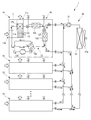
図1乃至図2は、本発明の一実施形態を示すものである。 1 and 2 show an embodiment of the present invention.
本発明の車両用空気調和装置1は、乗員が着座するためのシートが車室内に複数配置された車両において、シート毎に着座した乗員に向かって冷却又は加熱した空気を吹き出させるとともに、それぞれのシートの表面温度の調整を行うものである。
In the
車両用空気調和装置1は、図1に示すように、車室内における複数のシートのそれぞれの下部に設けられた複数の空調ユニット10と、車室内と車室外とにわたって設置され、複数の空調ユニット10が接続された熱媒体回路20と、を備えている。
As shown in FIG. 1, the
空調ユニット10は、直方体形状を有するケース11と、ケース11内に設けられた冷媒回路12と、を有している。
The
ケース11には、内部に車室内に吹き出す空気を流通させるための通風路11aが形成されている。通風路11aには、車室内及び車室外の少なくとも一方の空気を通風路11aに流入させるための空気流入口11bと、通風路11aを流通した空気を車室内に吹き出させるための空気流出口11cと、が形成されている。また、通風路11a内には、空気流入口11bから空気流出口11cに向かって空気を流通させるための送風機13と、通風路11aを流通する空気を加熱または冷却するための後述する第1利用側熱交換器と、が配置されている。
The
冷媒回路12は、吸入した冷媒を圧縮して吐出するための圧縮機12aと、通風路11aを流通する空気と冷媒とを熱交換するための第1利用側熱交換器12bと、シートの内部に設置されたシート用熱媒体回路14を流通する熱媒体と冷媒とを熱交換するための第2利用側熱交換器12cと、熱媒体回路20を流通する熱媒体と冷媒とを熱交換するための吸排熱側熱交換器12dと、冷媒回路12を流通する冷媒を減圧するための第1膨張弁12e及び第2膨張弁12fと、暖房運転用の冷媒流路と冷房運転用の冷媒流路とを切り替えるための流路切替手段としての四方弁12gと、を有している。
The
具体的に説明すると、圧縮機12aの冷媒吐出側及び冷媒吸入側には、四方弁12gを介して第1利用側熱交換器12bの一端側が接続されている。第1利用側熱交換器12bの他端側には、第1膨張弁12eを介して第2利用側熱交換器12cの冷媒流路一端側が接続されている。第2利用側熱交換器12cの冷媒流路他端側には、第2膨張弁12fを介して吸排熱側熱交換器12dの冷媒流路一端側が接続されている。吸排熱側熱交換器12dの冷媒流路他端側には、四方弁12gを介して圧縮機12aの冷媒吐出側及び冷媒吸入側が接続されている。
More specifically, one end side of the first use
第1膨張弁12e及び第2膨張弁12fは、それぞれ弁開度の調整が可能となっている。また、四方弁12gは、第1乃至第4接続口a,b,c,dを有し、第1接続口aと第2接続口bとを連通すると共に第3接続口cと第4接続口dとを連通する状態と、第1接続口aと第3接続口cとを連通すると共に第2接続口bと第4接続口dとを連通する状態と、を切り替え可能である。
Each of the
第2利用側熱交換器12cの熱媒体流路には、シートの内部に組み込まれたシート用熱媒体回路14が接続されている。シート用熱媒体回路14には、エチレングリコール等の不凍液や水が熱媒体として封入されている。
A sheet
熱媒体回路20には、エチレングリコール等の不凍液や水が熱媒体として流通する流路が形成されており、複数の空調ユニット10の冷媒回路12の吸排熱側熱交換器12dの熱媒体流路が互いに並列に接続されている。熱媒体回路20には、内部に封入された熱媒体を循環させるための循環ポンプ21と、車室外の空気と熱媒体とを熱交換するための室外熱交換器22と、が接続されている。室外熱交換器22は、車両のエンジンルーム等の車室外の空間に配置されている。また、室外熱交換器22の近傍には、車室外の空気を室外熱交換器22に向かって流通させるための室外送風機22aが設けられている。
The
以上のように構成された車両用空気調和装置1において、複数の空調ユニット10では、それぞれ、圧縮機12a及び送風機13を駆動するとともに、第1膨張弁12e及び第2膨張弁12fの弁開度と四方弁12gの流路を設定することで、暖房運転と冷房運転とが切り替えられる。また、熱媒体回路20では、循環ポンプ21及び室外送風機22aを駆動することで、空調ユニット10の吸排熱側熱交換器12dに対して冷媒と熱交換する熱媒体が供給される。
In the
空調ユニット10において暖房運転を行う場合には、図1に示すように、第1膨張弁12eの弁開度を全開に設定すると共に第2膨張弁12fを所定の弁開度に設定し、四方弁12gの第1接続口aと第2接続口bとを連通すると共に第3接続口cと第4接続口dとを連通する状態とする。
When performing heating operation in the
これにより、圧縮機12aから吐出された冷媒は、第1利用側熱交換器12b及び第2利用側熱交換器12cにおいて熱を放出し、吸排熱側熱交換器12dにおいて熱を吸収する。
Thereby, the refrigerant discharged from the
また、圧縮機12aから吐出された高温の冷媒は、まず、第1利用側熱交換器12bにおいて放熱して温度が低下する。次に、第1利用側熱交換器12bにおいて放熱して温度が低下した冷媒が、第2利用側熱交換器12cにおいてさらに放熱する。
Further, the high-temperature refrigerant discharged from the
即ち、暖房運転時において車室内に吹き出される空気は、車室内の目標設定温度と比較して高温が求められるため、圧縮機12aから吐出された高温の冷媒と熱交換した空気が車室内に吹き出される。また、暖房運転時におけるシートは、乗員が接することになり、車室内の目標設定温度に対して著しく高温となる状態を避ける必要があるため、第1利用側熱交換器12bにおいて放熱した後の冷媒と熱交換した熱媒体によってシートが加熱される。
That is, since the air blown into the vehicle interior during the heating operation is required to have a higher temperature than the target set temperature in the vehicle interior, the air exchanged heat with the high-temperature refrigerant discharged from the
また、空調ユニット10において冷房運転を行う場合には、図2に示すように、第1膨張弁12eの弁開度を所定の弁開度に設定すると共に第2膨張弁12fの弁開度を第1膨張弁12eの弁開度よりも大きい所定の弁開度に設定し、四方弁12gの第1接続口aと第3接続口cとを連通すると共に第2接続口bと第4接続口dとを連通する状態とする。
Further, when the cooling operation is performed in the
これにより、圧縮機12aから吐出された冷媒は、吸排熱側熱交換器12dにおいて熱を排出し、第1利用側熱交換器12b及び第2利用側熱交換器12cにおいて熱を吸収する。
Thereby, the refrigerant discharged from the
また、吸排熱側熱交換器12dから吐出した冷媒は、まず、第2膨張弁12fを第1膨張弁12eの弁開度よりも大きい所定の弁開度に設定することで、第2利用側熱交換器12cにおける吸熱量が所定の吸熱量に制限される。次に、第2利用側熱交換器12cから流出した冷媒は、第1膨張弁12eを所定の弁開度に設定することで、第1利用側熱交換器12bにおいて第2利用側熱交換器12cよりも大きな吸熱量とする。
In addition, the refrigerant discharged from the intake / exhaust heat
即ち、冷房運転時において車室内に吹き出される空気は、車室内の目標設定温度と比較して低温が求められるため、第2利用側熱交換器12cよりも大きな吸熱量となる第1利用側熱交換器12bにおいて冷媒と熱交換し、車室内に吹き出される。また、冷房運転時におけるシートは、乗員が接することになり、車室内の目標設定温度に対して著しく低温となる状態を避ける必要があるため、吸熱量が制限された第2利用側熱交換器12cにおいて冷媒と熱交換した熱媒体によってシートが冷却される。
That is, since the air blown into the vehicle interior during the cooling operation is required to have a lower temperature than the target set temperature in the vehicle interior, the first usage side has a larger heat absorption amount than the second usage
このように、本実施形態の車両用空気調和装置によれば、熱媒体回路20には、複数の空調ユニット10の冷媒回路12が接続されている。
Thus, according to the vehicle air conditioner of the present embodiment, the
これにより、複数の空調ユニット10を車室内のみに設置するとともに、1つの熱媒体回路20のみを車室内と車室外とにわたって設置することで車両用空気調和装置1を構成することができるので、車両用空気調和装置1の設置スペースの省スペース化を図ることが可能となる。
Thus, since the plurality of
また、冷媒回路12には、複数の利用側熱交換器12b,12cが互いに直列に接続されている。
The
これにより、利用側熱交換器12b,12cのそれぞれにおいて対象物を互いに異なる温度となるように冷却または加熱することができるので、車室内における乗員の快適性を向上させることが可能となる。
As a result, the object can be cooled or heated in the use
また、冷媒回路12は、利用側熱交換器12b,12cを、放熱器として機能させる暖房運転用の冷媒流路または吸熱器として機能させる冷房運転用の冷媒流路に切り替える四方弁12gを有している。
The
これにより、冷媒回路12において、暖房運転及び冷房運転のそれぞれにおいて第1利用側熱交換器12b及び第2利用側熱交換器12cによって対象物を加熱または冷却することが可能となるので、冷媒の流路を構成する管の使用量を低減することができ、製造コストの低減を図ることが可能となる。
Thereby, in the
また、複数の利用側熱交換器12b,12cのうち、冷媒流通方向の上流側に位置する利用側熱交換器(暖房運転における第1利用側熱交換器12b、冷房運転における第2利用側熱交換器12c)は、下流側に位置する利用側熱交換器において加熱または冷却される対象物の温度よりも高い温度に対象物を加熱または冷却する。
Of the plurality of usage-
これにより、暖房運転において高温が要求される空気を加熱する第1利用側熱交換器12bと、冷房運転において過度な低温を避ける必要がある熱媒体を冷却する第2利用側熱交換器12cと、を同一の冷媒回路12によって構成することが可能となる。
Thereby, the 1st utilization
尚、前記実施形態では、熱媒体回路20を流通する熱媒体を、室外熱交換器22において車室外の空気と熱交換させることによって、吸熱または放熱させるようにしたものを示したが、これに限られるものではない。流通する熱媒体の吸熱量が不足する状態を解消可能な熱媒体回路としては、例えば、図3に示すように、熱媒体回路20を流通する熱媒体を電力によって加熱するため加熱ヒータ23を、三方弁24を介して、室外熱交換器22と並列に接続してもよい。この場合には、熱媒体回路20を流通する熱媒体を加熱ヒータ23によって加熱することで冷媒回路12において不足する熱量を補うことが可能となる。
In the above-described embodiment, the heat medium flowing through the
また、車両がエンジン及び電動モータの一方または両方の駆動力によって走行するハイブリッド車両や、電動モータの駆動力で走行する電動車両等、走行用の電力を供給するためのバッテリを備えている場合には、図4に示すように、バッテリ25を冷却するための冷却回路を熱媒体回路20に接続してもよい。この場合には、バッテリ25を冷却するための冷却回路を別途設ける必要がなく、熱媒体回路20を流通する熱媒体によってバッテリ25を冷却することが可能となる。また、バッテリ25から排出される熱は、熱媒体回路20を流通する熱媒体に吸熱させることによって、冷媒回路12において不足する熱量を補うことが可能となる。
In addition, when the vehicle includes a battery for supplying electric power for traveling, such as a hybrid vehicle that travels by the driving force of one or both of the engine and the electric motor, or an electric vehicle that travels by the driving force of the electric motor. As shown in FIG. 4, a cooling circuit for cooling the
また、前記実施形態では、二つの利用側熱交換器12b,12cを接続した冷媒回路12を示したが、1つの利用側熱交換器を接続した冷媒回路に対しても、本発明を適用可能である。
Moreover, in the said embodiment, although the
また、前記実施形態では、冷媒回路12に対して、第1利用側熱交換器12b及び第2利用側熱交換器12cを互いに直列に接続し、加熱または冷却される対象物を互いに異なる温度とするようにしたものを示したが、これに限られるものではない。例えば、冷媒回路12に対して、3以上の利用側熱交換器を互いに直列に接続し、加熱または冷却する対象物を互いに異なる温度とするようにしてもよい。
Moreover, in the said embodiment, with respect to the
また、前記実施形態では、第1利用側熱交換器12bによって車室内に吹き出す空気の温度を加熱または冷却し、第2利用側熱交換器12cによってシート用熱媒体回路14を流通する熱媒体を加熱または冷却するものを示したが、これに限られるものではない。例えば、第1利用側熱交換器12b及び第2利用側熱交換器12cのそれぞれにおいて車室内に供給する空気を互いに異なる温度に加熱または冷却してもよい。また、第1利用側熱交換器12b及び第2利用側熱交換器12cのそれぞれにおいて液体の熱媒体を互いに異なる温度に加熱または冷却してもよい。
Moreover, in the said embodiment, the temperature of the air which blows off into a vehicle interior is heated or cooled by the 1st utilization
また、前記実施形態では、四方弁12gによって冷媒回路12を、冷房運転用の冷媒流路または暖房運転用の冷媒流路に切り替えるようにしたものを示したが、これに限られるものではない。冷媒回路12を、複数の開閉弁によって冷房運転用の冷媒流路または暖房運転用の冷媒流路に切り替えが可能となるように構成してもよい。
In the above embodiment, the
また、前記実施形態では、本発明を、暖房運転または冷房運転に切り替え可能な冷媒回路12に適用したものを示したが、これに限られるものではない。例えば、暖房運転専用の冷媒回路や冷房運転専用の冷媒回路に対して、本発明を適用することも可能である。
Moreover, in the said embodiment, although what applied this invention to the
1…車両用空気調和装置、10…空調ユニット、12…冷媒回路、12b…第1利用側熱交換器、12c…第2利用側熱交換器、12d…吸排熱側熱交換器、12g…四方弁、20…熱媒体回路、22…室外熱交換器、23…加熱ヒータ、25…バッテリ。
DESCRIPTION OF
Claims (6)
吸排熱側熱交換器において冷媒と熱交換する熱媒体が流通し、熱媒体と車室外の空気とを熱交換させる室外熱交換器が接続された熱媒体回路と、を備え、
熱媒体回路には、複数の冷媒回路が接続されている
車両用空気調和装置。 A refrigerant circuit connected to a use-side heat exchanger that heats or cools an object in a vehicle, and an intake / exhaust heat-side heat exchanger that absorbs heat discharged from the use-side heat exchanger or discharges the absorbed heat; ,
A heat medium circuit through which a heat medium that exchanges heat with the refrigerant flows in the intake / exhaust heat side heat exchanger, and an outdoor heat exchanger that exchanges heat between the heat medium and air outside the vehicle compartment, and
A vehicle air conditioner in which a plurality of refrigerant circuits are connected to the heat medium circuit.
請求項1に記載の車両用空気調和装置。 The vehicle air conditioner according to claim 1, wherein a plurality of usage-side heat exchangers are connected in series to the refrigerant circuit.
請求項1または2に記載の車両用空気調和装置。 The refrigerant circuit includes a flow path switching unit that switches the use-side heat exchanger to a refrigerant path for heating operation that functions as a radiator or a refrigerant path for cooling operation that functions as a heat absorber. Or the air conditioning apparatus for vehicles of 2.
請求項2または3に記載の車両用空気調和装置。 Among the plurality of use side heat exchangers, the use side heat exchanger located on the upstream side in the refrigerant flow direction has a temperature higher than the temperature of the object to be heated or cooled in the use side heat exchanger located on the downstream side. The vehicle air conditioner according to claim 2, wherein the object is heated or cooled.
請求項1乃至4のいずれかに記載の車両用空気調和装置。 The vehicle air conditioner according to any one of claims 1 to 4, wherein the heat medium circuit is provided with a heater that heats the heat medium flowing through the heat medium circuit.
請求項1乃至5のいずれかに記載の車両用空気調和装置。 The vehicle air conditioner according to any one of claims 1 to 5, wherein a cooling circuit for cooling a battery that supplies electric power when the vehicle is driven by an electric motor is connected to the heat medium circuit.
Priority Applications (2)
| Application Number | Priority Date | Filing Date | Title |
|---|---|---|---|
| JP2018056234A JP2019166972A (en) | 2018-03-23 | 2018-03-23 | Air conditioner for vehicle |
| PCT/JP2019/009850 WO2019181627A1 (en) | 2018-03-23 | 2019-03-12 | Air conditioning device for vehicle |
Applications Claiming Priority (1)
| Application Number | Priority Date | Filing Date | Title |
|---|---|---|---|
| JP2018056234A JP2019166972A (en) | 2018-03-23 | 2018-03-23 | Air conditioner for vehicle |
Publications (1)
| Publication Number | Publication Date |
|---|---|
| JP2019166972A true JP2019166972A (en) | 2019-10-03 |
Family
ID=67987227
Family Applications (1)
| Application Number | Title | Priority Date | Filing Date |
|---|---|---|---|
| JP2018056234A Pending JP2019166972A (en) | 2018-03-23 | 2018-03-23 | Air conditioner for vehicle |
Country Status (2)
| Country | Link |
|---|---|
| JP (1) | JP2019166972A (en) |
| WO (1) | WO2019181627A1 (en) |
Family Cites Families (10)
| Publication number | Priority date | Publication date | Assignee | Title |
|---|---|---|---|---|
| JPH0798450B2 (en) * | 1985-10-21 | 1995-10-25 | 富士重工業株式会社 | Vehicle cooling system |
| JPH0939555A (en) * | 1995-08-02 | 1997-02-10 | Matsushita Electric Ind Co Ltd | Heat pump heating, cooling and dehumidifying device for electric automobile |
| JP3436872B2 (en) * | 1997-11-07 | 2003-08-18 | 株式会社テージーケー | Automotive air conditioners |
| JP2006131106A (en) * | 2004-11-05 | 2006-05-25 | Denso Corp | Air-conditioner for vehicle |
| JP2006327428A (en) * | 2005-05-26 | 2006-12-07 | Denso Corp | Vehicular air-conditioner |
| KR20110131885A (en) * | 2010-06-01 | 2011-12-07 | 한라공조주식회사 | Seat air conditioner for vehicle |
| JP6327038B2 (en) * | 2014-07-23 | 2018-05-23 | 株式会社デンソー | Air conditioner for vehicles |
| JP6380265B2 (en) * | 2014-07-23 | 2018-08-29 | 株式会社デンソー | Refrigeration cycle equipment |
| DE112015005666T5 (en) * | 2014-12-19 | 2017-09-14 | Gentherm Incorporated | Thermal conditioning systems and methods for vehicle areas |
| JP6439476B2 (en) * | 2015-02-09 | 2018-12-19 | 株式会社デンソー | Seat air conditioner |
-
2018
- 2018-03-23 JP JP2018056234A patent/JP2019166972A/en active Pending
-
2019
- 2019-03-12 WO PCT/JP2019/009850 patent/WO2019181627A1/en active Application Filing
Also Published As
| Publication number | Publication date |
|---|---|
| WO2019181627A1 (en) | 2019-09-26 |
Similar Documents
| Publication | Publication Date | Title |
|---|---|---|
| US9931905B2 (en) | Air conditioning device for vehicle | |
| JP4505510B2 (en) | Vehicle air conditioning system | |
| WO2020108532A1 (en) | Vehicle thermal management system and control method therefor, and vehicle | |
| CN111231620B (en) | Vehicle thermal management system, control method thereof and vehicle | |
| JP2009184493A (en) | Air conditioning system for vehicle | |
| CN111231655B (en) | Vehicle thermal management system, control method thereof and vehicle | |
| CN111231772B (en) | Vehicle thermal management system, control method thereof and vehicle | |
| JPWO2015011918A1 (en) | Air conditioner for vehicles | |
| KR101225660B1 (en) | An auxiliary cooling and heating device for automobile using thermo element module and its controlling method thereof | |
| JP5817824B2 (en) | Vehicle air conditioner | |
| WO2019230118A1 (en) | Vehicle air-conditioning apparatus | |
| WO2020158207A1 (en) | Vehicle air conditioner | |
| US20120222429A1 (en) | Vehicle air conditioner | |
| WO2019181627A1 (en) | Air conditioning device for vehicle | |
| CN114643829A (en) | Vehicle-mounted semiconductor air conditioning system | |
| WO2019230117A1 (en) | Vehicle air-conditioning apparatus | |
| WO2020059353A1 (en) | Vehicle air conditioner | |
| JP7097345B2 (en) | Vehicle air conditioner | |
| JP7098866B2 (en) | Vehicle air conditioner | |
| WO2024009577A1 (en) | System for adjusting temperature of battery, and vehicular system for managing heat | |
| WO2023243367A1 (en) | Vehicle air-conditioning device | |
| WO2020059354A1 (en) | Vehicle air conditioner | |
| KR20080008867A (en) | Assistance cooling and heating device for automobile using thermoelectric element | |
| JP2020104567A (en) | Vehicular air conditioner |