CN102848413A - SLD (Super Luminescent Diode) automatic cutting and paving machine - Google Patents
SLD (Super Luminescent Diode) automatic cutting and paving machine Download PDFInfo
- Publication number
- CN102848413A CN102848413A CN2012103508079A CN201210350807A CN102848413A CN 102848413 A CN102848413 A CN 102848413A CN 2012103508079 A CN2012103508079 A CN 2012103508079A CN 201210350807 A CN201210350807 A CN 201210350807A CN 102848413 A CN102848413 A CN 102848413A
- Authority
- CN
- China
- Prior art keywords
- tpt
- cylinder
- eva
- frame
- automatic
- Prior art date
- Legal status (The legal status is an assumption and is not a legal conclusion. Google has not performed a legal analysis and makes no representation as to the accuracy of the status listed.)
- Granted
Links
Images

Abstract
The invention discloses an SLD (Super Luminescent Diode) automatic cutting and paving machine comprising an EVA (Ethylene Vinyl Acetate Copolymer) and TPT (Topotecan Hydrochloride) automatic cutting system and an automatic paving system located on the EVA and TPT automatic cutting system, wherein discharging devices and two punching devices and two cutting devices respectively connected with the two discharging devices are respectively arranged on the two ends of the EVA and TPT automatic cutting system, a material clamping and conveying device is arranged at the middle part of the EVA and TPT automatic cutting system, and the automatic paving system comprises a material paving device. Compared with the prior art, the machine has the advantages that the cutting and paving operations of solar cell panel EVA, TPT are integrated, so that the structure is compact and the operation is smooth and continuous, the locating and length fixing precisions in the cutting and punching operation are higher, the production benefit and the product quality are improved, and the manpower, physical resources and factory building space are saved.
Description
Technical field
The present invention relates to a kind of solar panel EVA, TPT and automatically cut laydown machine, especially a kind of automation equipment of laying interlock that cuts.
Background technology
Solar energy production producer is divided into two procedures with cutting of solar panel EVA, TPT with laying to finish on the market at present.Cut by automatic cutter finish cut, punching and stacking, laying then is generally to adopt EVA, the TPT that manually will cut to lay.Utilize traditional handicraft: the first, caused the waste in manpower and space.The second, inefficiency can't satisfy the now high efficiency production requirement of solar cell board assembly line.The 3rd, precision is low, and error is large, and multiplicity is not high.In view of this be necessary to provide a kind of SLD automatically to cut laydown machine, change traditional handicraft, will cut, lay the interlock combination, it is integrated to realize that solar panel EVA, TPT cut, lay, and really satisfies the automation requirement of solar cell board assembly line.
Summary of the invention
In view of above-mentioned condition, the object of the present invention is to provide a kind of SLD automatically to cut laydown machine, described SLD cuts laydown machine automatically will cut a slice to EVA, the TPT of solar panel, lay a slice, realize that EVA, TPT cut and disposable the finishing of laying.And it has the higher precision that cuts in cutting process, have higher multiplicity in process of deployment.Whole technical process is smooth to link up, and will enhance productivity greatly.
For achieving the above object, the present invention is achieved by the following technical solutions:
A kind of SLD cuts laydown machine automatically, comprise EVA, TPT automatic cutting system and be positioned at automatic paving system on described EVA, the TPT automatic cutting system, described EVA, TPT automatic cutting system two ends respectively arrange discharging device, with with two the cover discharging devices be connected respectively two the cover hole punched devices and two the cover cutting means, have a material folding conveying device in the middle of being positioned at EVA, TPT automatic cutting system, described automatic paving system comprises the material laying apparatus.
In the present invention, mentioned discharging device, comprise and being fixed on the described carriage with the stock roll that drives, and horizontally disposed First Transition roll shaft, the second transition roll shaft, have unsteady roller bearing between described First Transition roll shaft and the second transition roll shaft, it is intermeshing with the tooth bar that is fixed on the carriage that described roller bearing two ends are provided with gear.
In the present invention, described hole punched device, comprise the driving cylinder that is set up in parallel, this drives cylinder and connects clamping piece and stamping knife frame, and be installed in the spring that drives between cylinder and the clamping piece, also include cylinder, be connected with weight in being installed in fairlead by cylinder, have a stamping knife on the stamping knife frame of corresponding weight lower end.
In the present invention, described cutting means comprises that material hold-down mechanism and cutting knife motion two parts form; Described material hold-down mechanism comprises the first clamping frame of being comprised of clamping frame on first and first time clamping frame and the second clamping frame that is comprised of clamping frame on second and second time clamping frame, wherein the first clamping frame is provided with cylinder, and described the second clamping frame is provided with upper cylinder and lower cylinder; Described cutting knife motion comprises the Rodless cylinder that is installed on the carriage, at described Rodless cylinder solid knife rest and blade is installed.
In the present invention, described material folding conveying device, comprise that carriage is provided with line slide rail, at line slide rail electronic slide unit is installed, this electronic slide unit is provided with the clamping support body, dispose servomotor and approach switch on the described electronic slide unit, described clamping support body two ends respectively are provided with row's double-piston gas pawl, are respectively equipped with the upper anchor clamps and the lower clamp that clamp or loosen for to EVA or TPT material on the upper lower piston of described two row's double-piston gas pawls.
In the present invention, described material laying apparatus, comprise being installed in and be arranged with line slide rail on the cross beam frame, the straight line electric slide unit is installed on this line slide rail, this straight line electric slide unit is connected with drive motors, at described straight line electric slide unit walking frame body is set, and this walking frame body is provided with lift cylinder, be connected with framed bent by lift cylinder, be distributed with sucker at described framed bent.
The present invention is that SLD cuts laydown machine automatically, is to utilize touch-screen to be connected with the PLC interface, controls by PLC pick-up transducers signal.Belong to prior art, be not repeated.
The beneficial effect that the present invention compared with prior art has is: with solar panel EVA, TPT cut with lay integrated, compact conformation, smooth linking up, and cut with punching location, fixed length precision higher, improve productivity effect and product quality, saved manpower and materials and factory building space.
Description of drawings
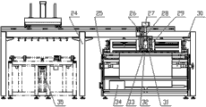
Fig. 1 is front view of the present invention;
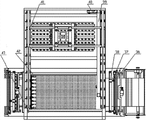
Fig. 2 is Fig. 1 right view;
Fig. 3 is Fig. 1 top view.
The specific embodiment
Below in conjunction with accompanying drawing the present invention is described in further detail.
SLD as shown in Figure 1 to Figure 3 cuts laydown machine automatically, comprise EVA, TPT automatic cutting system and be positioned at automatic paving system on described EVA, the TPT automatic cutting system, described EVA, TPT automatic cutting system two ends respectively arrange cover discharging device, hole punched device and a cutting means, have a material folding conveying device in the middle of being positioned at EVA, TPT automatic cutting system, described automatic paving system comprises the material laying apparatus.The described discharging device of present embodiment, comprise and being fixed on the described carriage 25 with the EVA stock roll 1 and the TPT stock roll 14 that drive, and horizontally disposed First Transition roll shaft 2, the second transition roll shaft 3, have unsteady roller bearing 23 between described First Transition roll shaft 2 and the second transition roll shaft 3, it is intermeshing with the tooth bar 16 that is fixed on the carriage 25 that described roller bearing 23 two ends are provided with gear 15.Carry out respectively blowing by stock roll 1 and stock roll 14.Wherein said EVA stock roll 1, TPT stock roll 14 are installed in respectively vapour-pressure type main axis of dilatation 30, this vapour-pressure type main axis of dilatation 30 drives EVA stock roll 1 and TPT stock roll 14 by buncher 34, the installation set-up mode of its three and described carriage 25, be techniques well known, just be not repeated at this.The hole punched device of present embodiment, comprise the driving cylinder 29 that is set up in parallel, this drives cylinder 29 and connects clamping piece 32 and stamping knife frame 33, and be installed in the spring 31 that drives between cylinder 29 and the clamping piece 32, also include cylinder 26, be connected with weight 27 in being installed in fairlead 28 by cylinder 26, have a stamping knife on the stamping knife frame 33 of corresponding weight 27 lower ends.By the clamping piece 32 and the stamping knife frame 33 that drive cylinder 29 and drive simultaneously, be arranged at the spring 31 that drives between cylinder 29 and the clamping piece 32 for increasing thrust, give the weight 27 of stamping knife power, support the cylinder 26 of described weight 27 and the fairlead 28 that described weight 27 moves both vertically.Driving cylinder 29 of the present invention is depressed clamping piece 32 and stamping knife frame 33 after mass transport puts in place, cylinder 26 actions, the supporting role that weight 27 loses cylinder 26 is done the movement of falling object and will be pounded to stamping knife and carry out punching, after having rushed the hole, driving cylinder 29 drive clamping pieces 32 and stamping knife frame 33 resets, while jack-up weight 27, weight 27 is supported in cylinder 26 actions again, and the material that has rushed the hole continues to carry.The cutting means of present embodiment comprises material hold-down mechanism and cutting knife motion two parts; Described material hold-down mechanism comprises the first clamping frame that is connected to form by clamping frame 12 on first and first time clamping frame 13, the second clamping frame that is connected to form by clamping frame 10 on second and second time clamping frame 9; Wherein first time clamping frame 13 at the first clamping frame is provided with cylinder 17, first time clamping frame 13 is installed on the carriage 25, described the second clamping frame second on clamping frame 10 be connected with upper cylinder 11, second time clamping frame 9 of the second clamping frame is connected with lower cylinder 18.Described cutting knife motion comprises the Rodless cylinder 38 that is installed on the carriage, at described Rodless cylinder 38 solid knife rest 37 and blade 36 is installed.When mass transport put in place, described the first clamping frame and the second clamping frame moved the compression material simultaneously, and Rodless cylinder 38 passes the tool slot that is arranged on the second clamping frame with cutting blade 36 and cuts.To be cut cutting into, the second clamping frame unclamps, and the material that has cut is transported away by described clamping support body 22, treats that above-mentioned clamping support body 22 loops back again, and after material was clamped by described upper anchor clamps 19 and lower clamp 20, the first clamping frame unclamped, and material continues to carry.The material folding conveying device of present embodiment, comprise that carriage 25 is provided with line slide rail 43, at line slide rail 43 electronic slide unit 42 is installed, this electronic slide unit 42 is provided with clamping support body 22, dispose servomotor 40 and approach switch (not marking among the figure) on the described electronic slide unit 42, accurately control the operation of described clamping support body 22.Described clamping support body 22 two ends respectively be provided with row's double-piston gas pawl 21, two row's double-piston gas pawls 21 can be after described clamping support body 22 operations put in place action drive lower piston on two row's double-piston gas pawls 21 and be respectively equipped with upper anchor clamps 19 and the lower clamp 20 that clamps or loosen for to EVA or TPT material.More steady for the material folding conveying, material folding conveying device of the present invention is combined with discharging device, plays the effect of balance material tension force.The material laying apparatus of present embodiment, comprise being installed in and be arranged with line slide rail 4 on the cross beam frame 24, straight line electric slide unit 39 is installed on this line slide rail 4, this straight line electric slide unit 39 is connected with drive motors 40, at described straight line electric slide unit 39 walking frame body 41 is set, this walking frame body 41 is provided with lift cylinder 6, is connected with framed bent 5 by lift cylinder 6, is distributed with sucker 8 at described framed bent 5.In the present embodiment, be provided with for the guiding lift cylinder 6 linear bearing 7.Described lift cylinder 6 moves after the mass transport that punching has cut puts in place, driving framed bent 5 descends, after touching material, the small-sized sucker 8 that some is arranged picks up material by having on the framed bent 5, lift cylinder 6 actions drive framed bent 5 and reset, the high-precision electronic slide unit 39 of present embodiment obtains walking frame body 41 that signalizing activity drives the upper material of crawl and is delivered to and lays table top 35 tops, again moves material put to laying table top 35 by lift cylinder 6 and finishes laying.
In addition, the present invention also comprises touch-screen, to show the material volume specification on the touch screen interface, material volume surplus has cut number, miscue etc., also can arrange and to cut number, the hommization action buttons such as initial point resets (control and display part adhere to prior art separately, have only designed the function software content, do not provide among the figure).
SLD of the present invention automatically cuts laydown machine and has finished and cut a slice EVA, lay a slice EVA, cut a slice TPT, lay a series of do actions such as a slice TPT, whole procedure structure is compact, and flow process links up, the former technological process of comparing, saved a large amount of factory building spaces, saved nearly 6 people of manpower, efficient has improved three times more than.Its specific performance is as follows simultaneously: cutoff length: 0---2000mm, and raw material wide cut: 0---1200mm cuts thickness 0.1---3mm, cuts precision (length direction): ± 0.5mm; (diagonal): ± 1mm lays and repeats to read: ± 0.5mm.
Claims (6)
1. a SLD cuts laydown machine automatically, it is characterized in that, comprise EVA, TPT automatic cutting system and be positioned at automatic paving system on described EVA, the TPT automatic cutting system, described EVA, TPT automatic cutting system two ends respectively arrange discharging device, with with two the cover discharging devices be connected respectively two the cover hole punched devices and two the cover cutting means, have a material folding conveying device in the middle of being positioned at EVA, TPT automatic cutting system, described automatic paving system comprises the material laying apparatus.
2. SLD according to claim 1 cuts laydown machine automatically, it is characterized in that, discharging device wherein, comprise and be fixed in upper EVA, the TPT stock roll (1,14) with driving of described carriage (25), and horizontally disposed First Transition roll shaft (2), the second transition roll shaft (3), be positioned between described First Transition roll shaft (2) and the second transition roll shaft (3) and have unsteady roller bearing (23), it is intermeshing with the tooth bar (16) that is fixed on the carriage (25) that described roller bearing (23) two ends are provided with gear (15).
3. SLD according to claim 1 cuts laydown machine automatically, it is characterized in that, wherein cutting means comprises that material hold-down mechanism and cutting knife motion two parts form; Described material hold-down mechanism comprises the first clamping frame of being comprised of clamping frame (12) on first and first time clamping frame (13) and the second clamping frame that is comprised of clamping frame (10) on second and second time clamping frame (9), wherein the first clamping frame is provided with cylinder (17), is respectively equipped with upper cylinder (11) and lower cylinder (18) on described the second clamping frame; Described cutting knife motion comprises the Rodless cylinder (38) that is installed on the carriage (25), at described Rodless cylinder solid knife rest (37) and blade (36) is installed.
4. SLD according to claim 1 cuts laydown machine automatically, it is characterized in that, hole punched device wherein, comprise the driving cylinder (29) that is set up in parallel, this drives cylinder (29) and connects clamping piece (32) and stamping knife frame (33), and be installed in the spring (31) that drives between cylinder (29) and the clamping piece (32), also include cylinder (26), be connected with the weight (27) that is installed in the fairlead (28) by cylinder (26), corresponding weight (27) lower end (stamping knife frame (33) on) has a stamping knife.
5. SLD according to claim 1 cuts laydown machine automatically, it is characterized in that, wherein material folding conveying device, comprise that carriage (25) is provided with line slide rail (43), at line slide rail (43) electronic slide unit (42) is installed, this electronic slide unit (42) is provided with clamping support body (22), dispose servomotor (40) and approach switch on the described electronic slide unit (42), described clamping support body (22) two ends respectively are provided with row's double-piston gas pawl (21), are respectively equipped with upper anchor clamps (19) and the lower clamp (20) that clamps or loosen for to EVA or TPT material on the upper lower piston of described two row's double-piston gas pawls (21).
6. SLD according to claim 1 cuts laydown machine automatically, it is characterized in that, wherein the material laying apparatus comprises that laying apparatus comprises being installed in and is arranged with line slide rail (4) on the cross beam frame (24), the upper straight line electric slide unit (39) of installing of this line slide rail (4), this straight line electric slide unit (39) is connected with drive motors (40), at described straight line electric slide unit (39) walking frame body (41) is set, this walking frame body (41) is provided with lift cylinder (6), be connected with framed bent (5) by lift cylinder (6), be distributed with sucker (8) at described framed bent (5).
Priority Applications (1)
| Application Number | Priority Date | Filing Date | Title |
|---|---|---|---|
| CN201210350807.9A CN102848413B (en) | 2012-09-20 | 2012-09-20 | SLD cuts laydown machine automatically |
Applications Claiming Priority (1)
| Application Number | Priority Date | Filing Date | Title |
|---|---|---|---|
| CN201210350807.9A CN102848413B (en) | 2012-09-20 | 2012-09-20 | SLD cuts laydown machine automatically |
Publications (2)
| Publication Number | Publication Date |
|---|---|
| CN102848413A true CN102848413A (en) | 2013-01-02 |
| CN102848413B CN102848413B (en) | 2015-09-09 |
Family
ID=47395586
Family Applications (1)
| Application Number | Title | Priority Date | Filing Date |
|---|---|---|---|
| CN201210350807.9A Active CN102848413B (en) | 2012-09-20 | 2012-09-20 | SLD cuts laydown machine automatically |
Country Status (1)
| Country | Link |
|---|---|
| CN (1) | CN102848413B (en) |
Cited By (7)
| Publication number | Priority date | Publication date | Assignee | Title |
|---|---|---|---|---|
| CN103231416A (en) * | 2013-04-22 | 2013-08-07 | 江苏省常州技师学院 | Automatic cutting device for solar module film |
| CN103934859A (en) * | 2014-04-30 | 2014-07-23 | 鲁吉志 | Auxiliary material continuous stamping method and device |
| CN104608969A (en) * | 2015-01-22 | 2015-05-13 | 河南金谷实业发展有限公司 | Device and method for orderly stacking woven bags |
| CN105382881A (en) * | 2015-12-18 | 2016-03-09 | 青岛农业大学 | Puncher for countercurrent immunoelectrophoresis agar plate |
| CN105870256A (en) * | 2016-05-09 | 2016-08-17 | 无锡市精电技术有限公司 | EVA-TPT synchronous cutting and laying machine |
| CN106827001A (en) * | 2016-12-23 | 2017-06-13 | 郑飞 | A kind of plastic plate grooving apparatus |
| CN112123817A (en) * | 2020-09-14 | 2020-12-25 | 常州市新创智能科技有限公司 | Automatic processing equipment for blade main beam |
Citations (8)
| Publication number | Priority date | Publication date | Assignee | Title |
|---|---|---|---|---|
| WO2009036248A2 (en) * | 2007-09-12 | 2009-03-19 | Springs Window Fashions, Llc | Cutdown machine for coverings to fit architectural openings |
| JP2010194621A (en) * | 2009-02-23 | 2010-09-09 | Toko Tokyo Branch Co Ltd | Pressing device for sheet material, press line of the sheet material by use of the pressing device, and sheet material processing method |
| CN201601143U (en) * | 2009-12-17 | 2010-10-06 | 常州德茂自动化科技有限公司 | Solar panel EVA film spreading machine |
| KR20100130669A (en) * | 2009-06-04 | 2010-12-14 | 조길수 | Photovoltaic fiber, apparatus and method of manufacturing the same |
| CN102157604A (en) * | 2010-12-02 | 2011-08-17 | 张云峰 | Solar cell panel packaging material laying machine |
| CN202181134U (en) * | 2011-06-27 | 2012-04-04 | 上海博显实业有限公司 | Integrated full-automatic cutting machine |
| CN202292838U (en) * | 2011-09-22 | 2012-07-04 | 炘源晶光伏科技(洛阳)有限公司 | Cutting device for solar cell assembly back panel |
| CN202412868U (en) * | 2011-12-23 | 2012-09-05 | 常州天华新能源科技有限公司 | Intelligent laying production equipment for crystalline silicon solar laminated board |
-
2012
- 2012-09-20 CN CN201210350807.9A patent/CN102848413B/en active Active
Patent Citations (9)
| Publication number | Priority date | Publication date | Assignee | Title |
|---|---|---|---|---|
| WO2009036248A2 (en) * | 2007-09-12 | 2009-03-19 | Springs Window Fashions, Llc | Cutdown machine for coverings to fit architectural openings |
| WO2009036248A3 (en) * | 2007-09-12 | 2009-06-11 | Springs Window Fashions Llc | Cutdown machine for coverings to fit architectural openings |
| JP2010194621A (en) * | 2009-02-23 | 2010-09-09 | Toko Tokyo Branch Co Ltd | Pressing device for sheet material, press line of the sheet material by use of the pressing device, and sheet material processing method |
| KR20100130669A (en) * | 2009-06-04 | 2010-12-14 | 조길수 | Photovoltaic fiber, apparatus and method of manufacturing the same |
| CN201601143U (en) * | 2009-12-17 | 2010-10-06 | 常州德茂自动化科技有限公司 | Solar panel EVA film spreading machine |
| CN102157604A (en) * | 2010-12-02 | 2011-08-17 | 张云峰 | Solar cell panel packaging material laying machine |
| CN202181134U (en) * | 2011-06-27 | 2012-04-04 | 上海博显实业有限公司 | Integrated full-automatic cutting machine |
| CN202292838U (en) * | 2011-09-22 | 2012-07-04 | 炘源晶光伏科技(洛阳)有限公司 | Cutting device for solar cell assembly back panel |
| CN202412868U (en) * | 2011-12-23 | 2012-09-05 | 常州天华新能源科技有限公司 | Intelligent laying production equipment for crystalline silicon solar laminated board |
Cited By (10)
| Publication number | Priority date | Publication date | Assignee | Title |
|---|---|---|---|---|
| CN103231416A (en) * | 2013-04-22 | 2013-08-07 | 江苏省常州技师学院 | Automatic cutting device for solar module film |
| CN103934859A (en) * | 2014-04-30 | 2014-07-23 | 鲁吉志 | Auxiliary material continuous stamping method and device |
| CN104608969A (en) * | 2015-01-22 | 2015-05-13 | 河南金谷实业发展有限公司 | Device and method for orderly stacking woven bags |
| CN104608969B (en) * | 2015-01-22 | 2016-09-07 | 河南金谷实业发展有限公司 | A kind of neat device and method of woven bag code |
| CN105382881A (en) * | 2015-12-18 | 2016-03-09 | 青岛农业大学 | Puncher for countercurrent immunoelectrophoresis agar plate |
| CN105870256A (en) * | 2016-05-09 | 2016-08-17 | 无锡市精电技术有限公司 | EVA-TPT synchronous cutting and laying machine |
| CN106827001A (en) * | 2016-12-23 | 2017-06-13 | 郑飞 | A kind of plastic plate grooving apparatus |
| CN106827001B (en) * | 2016-12-23 | 2018-09-04 | 安徽韩华建材科技股份有限公司 | A kind of plastic plate grooving apparatus |
| CN112123817A (en) * | 2020-09-14 | 2020-12-25 | 常州市新创智能科技有限公司 | Automatic processing equipment for blade main beam |
| CN112123817B (en) * | 2020-09-14 | 2022-04-29 | 常州市新创智能科技有限公司 | Automatic processing equipment for blade main beam |
Also Published As
| Publication number | Publication date |
|---|---|
| CN102848413B (en) | 2015-09-09 |
Similar Documents
| Publication | Publication Date | Title |
|---|---|---|
| CN102848413B (en) | SLD cuts laydown machine automatically | |
| CN201122605Y (en) | LED automatic pin cutting machine | |
| CN102380893B (en) | Automatic multi-blade saw for mold pressing plate | |
| CN101586171B (en) | Leather cutting machine | |
| CN204917198U (en) | Asynchronous material loading work or material rest in duplex position | |
| CN204078149U (en) | A kind of novel glass paving paper machine | |
| CN203958744U (en) | The automatic dispenser of dividing plate | |
| CN203622578U (en) | Feeding machine of multi-row multi-spindle drilling machine tool | |
| CN202861245U (en) | Fine blanking machine with full-automatic sheet feeding device | |
| CN201151133Y (en) | Positioning apparatus of cutting machine | |
| CN209440222U (en) | A kind of cutting mechanism of knitting machine | |
| CN102887653A (en) | Vacuum glass support pillar layout device | |
| CN202323342U (en) | Cloth feeding device for sewing machine with button hole | |
| CN202011047U (en) | Perforating machine for bamboo and wood | |
| CN215325249U (en) | Automatic sorting equipment for measuring thickness of plates | |
| CN202796897U (en) | Material-clamping device for BGA automatic ball mounter | |
| CN204906866U (en) | A automatic clicker for making flexible circuit board | |
| CN114378578A (en) | Type-C kludge | |
| CN102189568B (en) | Bamboo and wood punching machine | |
| CN208895566U (en) | Saw all-in-one machine is cut in a kind of metal form punching | |
| CN208247364U (en) | A kind of mobile phone light guide panel full-automatic cutting machine | |
| CN107812850B (en) | Automatic steel sheet feeder | |
| CN203830738U (en) | Synchronous moving type bar feeder | |
| CN202344601U (en) | Soft board segmenting machine | |
| CN207170757U (en) | A kind of billot stepping feeder frame |
Legal Events
| Date | Code | Title | Description |
|---|---|---|---|
| C06 | Publication | ||
| PB01 | Publication | ||
| SE01 | Entry into force of request for substantive examination | ||
| SE01 | Entry into force of request for substantive examination | ||
| C14 | Grant of patent or utility model | ||
| GR01 | Patent grant | ||
| C41 | Transfer of patent application or patent right or utility model | ||
| TR01 | Transfer of patent right |
Effective date of registration: 20170122 Address after: 066011 Longhai Road, Qinhuangdao economic and Technological Development Zone, Hebei, No. 88 Patentee after: Qinhuangdao Grand Valley Photovoltaic Technology Co., Ltd. Address before: Economic and Technological Development Zone, Jing River in Hebei province Qinhuangdao City No. 6 066004 Patentee before: QINHUANGDAO RISING SOLAR ENERGY SCIENCE AND TECHNOLOGY CO., LTD. |