The utility model content
Technical problem to be solved in the utility model is: a kind of LED cutter of automation is provided, avoids the defective of the traditional manual operation mode of production.
For solving the problems of the technologies described above, the utility model adopts following technical scheme: the automatic cutter of a kind of LED comprises frame, flat shake device, feed mechanism, cuts pin mould, light bulb head detent mechanism and control system; Described frame is carried all the other each assemblies, and frame comprises framework panel, support body, rewinding mouth and waste material funnel; Feed mechanism one end is accepted the flat device that shakes receiving the LED that arranges at a certain angle of the flat device output of shaking, and feed mechanism also is connected mutually so that LED is delivered to the light bulb head detent mechanism with the light bulb head detent mechanism and locatees; The described pin mould of cutting is located at light bulb head detent mechanism one side; Described control system is controlled described flat shake device, feed mechanism respectively, is cut pin mould and light bulb head detent mechanism.
Wherein, described feed mechanism comprises a feed appliance base plate, is provided with line slide rail in the front portion of feed appliance base plate, and the rear portion is provided with cylinder, and is provided with a delivery sheet slidably on line slide rail, and described delivery sheet links to each other with the cylinder head of cylinder.
Wherein, the described pin mould of cutting comprises a die shoe, be fixed with die on the die shoe, and die shoe protrudes upward the some guide pillars that are arranged with buffer spring, being equipped with by means of linear bearing at the guide pillar top can be along the up and down patrix top board of guide pillar, be fixed with the punch tool rest on the bottom surface of patrix top board, and blade behind the blade, punch before on the punch tool rest, by means of the compression spring punch being installed, but also in the bottom of punch tool rest the patrix stripper plate is installed by means of axostylus axostyle, axle sleeve.
Wherein, described light bulb head detent mechanism comprises the parallel big mould bases upper plate at the two ends up and down of some root posts, the big mould bases lower plate of relatively being arranged at respectively, the two ends that axle is adjusted in one rotation are connected to the adjustment rotating shaft right support abutment that is fixed on big mould bases upper plate bottom surface, adjust on the rotating shaft left support abutment, first end of described rotation adjustment axle is provided with regulating spring, and is provided with the adjustment micrometer at second end of rotation adjustment axle; Also be provided with two blocks of adjustment plates that stretch out and be provided with loose slot downwards in big mould bases upper plate bottom surface, an adjustment plate outside is provided with the sensitive switch control board therein, two tops of adjusting between the plate are fixed with the magnetic receiver that magnet is installed, and be provided with can be along the up and down air cylinder fixed plate of loose slot of adjusting plate in the bottom, and the side of described air cylinder fixed plate is connected in rotation by lateral strut and adjusts on the axle, the bottom surface of air cylinder fixed plate is fixed with a little cylinder, and the piston rod connector of little cylinder stretches out downwards and is fixedly connected with a light bulb head location-plate cross bearer by means of an adjusting screw(rod); Described light bulb head location-plate cross bearer also is connected in the bottom surface of air cylinder fixed plate by means of longitudinally guiding axle, linear bearing, light bulb head location-plate cross bearer bottom surface is fixed with the perpendicular bearing of a light bulb head location-plate; One side of the perpendicular bearing of light bulb head location-plate is equipped with laterally steering axle sleeve and positioning cylinder, be inserted with the laterally steering axle that passes the perpendicular bearing of described light bulb head location-plate in the laterally steering axle sleeve, and the cylinder piston rod connector of positioning cylinder also passes the perpendicular bearing of described light bulb head location-plate, on described laterally steering axle and cylinder piston rod connector, also be with a light bulb head location-plate, the shaft portion between light bulb head location-plate and the perpendicular bearing of light bulb head location-plate at the laterally steering axle also is arranged with spring, also is fixed with near the inductive switching plate on the light bulb head location-plate.
Wherein, described control system comprises touch-screen, PLC controller, fiber switch and control panel.
Wherein, has guide-localization mechanism between described feed mechanism and the light bulb head detent mechanism.
Wherein, described guide-localization mechanism comprises a back locating detent seat, be fixed with fixed claw axle left support abutment, fixed claw axle right support abutment respectively at locating detent seat two ends, back, and on fixed claw axle left support abutment, fixed claw axle right support abutment, by means of the locating detent axle locating detent is installed respectively, and one right location-plate is installed at the front end that fixed claw axle left support abutment front end is equipped with left location-plate, fixed claw axle right support abutment.
In the course of work, by manually the LED product being put into the flat device that shakes by correct direction, shake the neat feeding of device average rate to delivery sheet by flat, detecting product by fiber switch puts in place, signal feedback is to the work of PLC instruction feeding cylinder, feeding cylinder is sent to the light bulb head location-plate with product, and the light bulb head location-plate moves under the effect of spring and drives near the action of inductive switching plate, has detected product near switch and has entered.The feeding cylinder scraping wings returns to initial point.Product is at the light bulb head location-plate, and the effect of left and right sides location-plate and locating detent is accurately located down.The PLC output order, hydraulic cylinder works, the patrix top board that the pin mould is cut in promotion presses down, and finishes shear action, and hydraulic cylinder resets.Feeding cylinder is feeding once more, and scraping wings will be sheared good product and push the rewinding of rewinding mouth.
The beneficial effects of the utility model are: by flat shake device, feed mechanism product is directly delivered to and cut placement of foot, and cut pin automatically by cutting the pin mould, improved production efficiency that LED cuts the pin operation, reduced production cost, saved manpower and material resources.
Embodiment
As shown in Figure 1, be the overall schematic of a preferred implementation of the automatic cutter of the utility model LED, the automatic cutter of described LED comprises frame 1, flat shake device 2, feed mechanism 3, light bulb head detent mechanism 4, guide-localization mechanism 5, cuts pin mould 6 and control system.
Wherein, described frame 1 comprises framework panel, support body, rewinding mouth and waste material funnel.
Fig. 2 is the schematic diagram of the flat device 2 that shakes, and Fig. 3 is its decomposition texture schematic diagram.The flat device 2 that shakes comprises fiber switch fixed head 201, fiber switch vertical adjusting plate 202, elasticity striker plate fixed head 203, elasticity striker plate fixed lever 204, elasticity striker plate 205, elasticity striker plate pressing plate 206, elasticity backgauge panel seat 207, the right marker board 208 of feeding, feeding left bank flitch 209, marker board is adjusted seat 210, back striker plate 211, the right flitch 212 of deciding of facing left shakes, the plate 213 of trying to get to the heart of a matter shakes, back shroud 214, right guard shield plate 215, vibrating disk fixed head 216, the flat device spring leaf 217 that shakes, magnetic board fixed head 218, magnetic board 219, electromagnet is angle bar 220 fixedly, electromagnet is adjusted seat 221, latch plate fixed head 222, the flat fixedly upper plate 223 of device that shakes, the flat fixedly lower plate 224 of device of shaking, electromagnet 225, the right side shakes and coils fixed head 226, the horizontal fixed lever 227 of dish shakes, a left side shakes and coils fixed head 228, left side guard shield plate 229.The flat device 2 that shakes is when starting, and after electromagnet 225 energisings (being generally AC220V/50Hz), electromagnet produces magnetic attraction magnetic board 219; Under the effect of diode filter, make electromagnet 225 outages decontrol magnetic board 219.Form vibration in electromagnet attraction and the disconnection, shake device spring leaf 217, vibrating disk 218 and other component vibrations are put down in drive.The flat device 2 of shaking also is widely used at other field, at this its concrete structure and operation principle is not done too much and is given unnecessary details.
Fig. 4 is the schematic diagram of feed mechanism 3, and Fig. 5 is its decomposition texture schematic diagram.Feed mechanism 3 comprises that delivery sheet 301, line slide rail 302, line slide rail holder 303, cylinder head holder 304, feeding cylinder 305, cylinder tail holder 306, feed appliance base plate 307, the right pillar 308 of the flat device that shakes, feeding partly adjust base plate 309, flat device left side pillar 310, the cylinder head 311 of shaking.Wherein, line slide rail holder 303 is fixed in the front portion on the feed appliance base plate 307, and line slide rail 302 is fixed on the line slide rail holder 303, and delivery sheet 301 is slidably mounted on the line slide rail 302; The rear portion that feeding cylinder 305 is fixed on the feed appliance base plate 307 by means of cylinder tail holder 306, described cylinder head 311 is connected on the cylinder head holder 304 by means of a cylinder flake nipple pin 312, and cylinder head holder 304 also is fixedly linked with delivery sheet 301.Like this, during cylinder head 311 reciprocating motions, promptly then cylinder head holder 304 drives delivery sheet 301 synchronous reciprocating motions.The right pillar 308 of the flat device that shakes, flat 310 on the pillar in a device left side that shakes are individually fixed in feed appliance base plate 307 both sides and are supported in the both sides of the flat device 2 that shakes respectively.In addition, for ease of regulating the position of feed mechanism 3, adjust on the base plate 309 and feed appliance base plate 307 is installed on one, which is provided with many group installing holes, by reaching the horizontal level of regulating feed mechanism in the installing hole that feed appliance base plate 307 is installed on diverse location on the adjustment degree plate 309.Because it is wider in other traditional product manufacture fields application to be similar to this air-cylinder type reciprocating motion feeding style, and its concrete structure is just seldom given unnecessary details.
Fig. 6 is the schematic diagram of light bulb head detent mechanism 4, and Fig. 7 is its decomposition texture schematic diagram.Light bulb head detent mechanism 4 is by big mould bases upper plate 401, magnet 402, sensitive switch control board 403, magnetic receiver 404, adjust plate 405, air cylinder fixed plate 406, stingy cylinder 407, outer shaft sleeve 408 is adjusted in rotation, cover 409 in the axle is adjusted in rotation, adjust micrometer 410, adjust rotating shaft right support abutment 411, piston rod connector 412, adjusting screw(rod) roof pressure lid 413,417, longitudinally guiding axle 414, adjusting screw(rod) 415, linear bearing 416, adjusting screw(rod) base pressure lid 417, four root posts 419, light bulb head location-plate cross bearer 420, near inductive switching plate 421, cylinder piston rod connector 422, laterally steering axle 423, light bulb head location-plate 424, spring 425, the light bulb head location-plate erects bearing 427, laterally steering axle sleeve 428, positioning cylinder 429, big mould bases lower plate 430, axle 431 is adjusted in rotation, lateral strut 432, regulating spring 433, adjusting rotating shaft left support abutment 434 combines.Wherein, big mould bases upper plate 401, the big parallel respectively two ends up and down that relatively are arranged at four root posts 419 of mould bases lower plate 430.The two ends that axle 431 is adjusted in rotation are with cover 409 in the rotation adjustment axle respectively successively, outer shaft sleeve 408 is adjusted in rotation, and rotation adjust axle 431 by means of the rotation that is positioned at two ends adjust outer shaft sleeve 408 respectively with the adjustment rotating shaft right support abutment 411 that is fixed in big mould bases upper plate 401 bottom surfaces, adjusting rotating shaft left support abutment 434 connects, in the rotation adjustment axle of rotation adjustment axle 431 first ends, be plugged with regulating spring 433 in the cover 409, and in the rotation adjustment axle that rotates second end of adjusting axle 431, overlap to be plugged with in 409 and adjust micrometer 410, adjust micrometer 410 so that regulate, make rotation adjust axle 431 occurred level displacements.Also be provided with two blocks of adjustment plates 405 that stretch out downwards in big mould bases upper plate 401 bottom surfaces, adjust plate 405 and be provided with loose slot, adjustment plate 405 outsides also are provided with sensitive switch control board 403 therein.Two adjust that top between the plates 405 is fixed with magnetic receiver 404 that magnet 402 is installed and be provided with can be along the up and down air cylinder fixed plate 406 of loose slot of adjusting plate in the bottom, and the side of described air cylinder fixed plate 406 is connected in rotation by lateral strut 432 and adjusts on the axle 431.Stingy cylinder 407 is fixed in the bottom surface of described air cylinder fixed plate 406, the piston rod connector 412 of stingy cylinder 407 stretches out downwards, and be connected on the adjusting screw(rod) 415 by adjusting screw(rod) roof pressure lid 413, and the bottom of adjusting screw(rod) 415 is fixedly connected with light bulb head location-plate cross bearer 420 by adjusting screw(rod) base pressure lid 417, locking nut 418 again, and described light bulb head location-plate cross bearer 420 also is connected in the bottom surface of air cylinder fixed plate 406 by means of longitudinally guiding axle 414, linear bearing 416.The perpendicular bearing 427 of described light bulb head location-plate is fixed in light bulb head location-plate cross bearer 420 bottom surfaces, side at the perpendicular bearing 427 of light bulb head location-plate is equipped with laterally steering axle sleeve 428, positioning cylinder 429, and cylinder piston rod connector 422, laterally steering axle 423 passes light bulb head location-plate 424 and perpendicular bearing 427 of light bulb head location-plate and corresponding positioning cylinder 429 respectively, laterally steering axle sleeve 428 matches, and the shaft portion between light bulb head location-plate 424 and the perpendicular bearing 427 of light bulb head location-plate at laterally steering axle 423 also is arranged with spring 425, thereby described light bulb head location-plate 424 can be provided with the another side that the light bulb head location-plate erects bearing 427 versatilely along laterally steering axle 423, on light bulb head location-plate 424, also be fixed with near inductive switching plate 421 by means of diplopore nut 426.
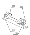
Fig. 8 is the schematic diagram of guide-localization mechanism 5, and Fig. 9 is its decomposition texture schematic diagram.Guide-localization mechanism 5 is combined by fixed claw axle left support abutment 501, locating detent 502,503, locating detent axle 504, fixed claw axle right support abutment 505, left and right sides location-plate 506, back locating detent seat 507.Wherein, back locating detent seat 507 is fixed on the big mould bases lower plate 430, fixed claw axle left support abutment 501, fixed claw axle right support abutment 505 are individually fixed in the two ends of back locating detent seat 507, on fixed claw axle left support abutment 501, fixed claw axle right support abutment 505, by means of locating detent axle 504 locating detent 502,503 is installed respectively, and one right location-plate 5062 is installed at the front end that fixed claw axle left support abutment 501 front ends are equipped with left location-plate 5061, fixed claw axle right support abutment 505.
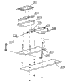
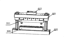
Figure 10 is a schematic diagram of cutting pin mould 6, and Figure 11 is its decomposition texture schematic diagram.Cut pin mould 6 and comprise that blade 609 behind blade 608 before the patrix top board 601, die shoe 602, guide pillar 603, linear bearing 604, buffer spring 605, die 606, punch tool rest 607, punch, the punch, compression spring 610, patrix stripper plate 611, top mold frame connect clamp 612 and hydraulic cylinder (scheming not shown).Wherein, described patrix top board 601, die shoe 602 be arranged in parallel up and down, link to each other by guide pillar 603, linear bearing 604 between the two, on guide pillar 603, also be arranged with buffer spring 605, thereby patrix top board 601 can be up and down along guide pillar 603, and cushion and provide resilience force by buffer spring 605.Die 606 is fixed on the die shoe 602,607 of punch tool rests are fixed on the bottom surface of patrix top board 601, blade 609 is installed on the punch tool rest 607 by means of compression spring 610 respectively behind the preceding blade 608 of described punch, the punch, and patrix stripper plate 611 is installed on the bottom of punch tool rest 607 by means of axostylus axostyle 613, axle sleeve 614.Described top mold frame connects the end face that clamp 612 is installed on patrix top board 601.Hydraulic cylinder is used to drive patrix top board 601 and does to pressing down to cut foot-propelled.
Described control system comprises touch-screen, PLC controller, fiber switch and control panel, is provided with a series of control commands in the PLC controller, and its program implementation mode comprises manually, automatically.Fiber switch is located on the fiber switch fixed head 201 of the flat device 2 that shakes, and inputs to the input port of PLC by fiber switch gained signal, feeds back to output by procedure identification.The output port of PLC sends the executive components such as hydraulic cylinder that dependent instruction is controlled the feeding cylinder of the electromagnet of the flat device that shakes, feed mechanism, cut the pin mould, make motion carry out predetermined actions, motion has also just been finished product 7 and has been sent into, locatees, cut processes such as pin, rewinding when carrying out predetermined action.
Figure 12 and Figure 13 are the working state schematic representations of the automatic cutter of the utility model LED.In the concrete running, the start opening power, be transformed into automatic work, each working terminal resets to operating state, and it is suitable that the frequency of putting down the device 2 that shakes is adjusted to, by manually LED product 7 being put into the flat device 2 that shakes by correct direction, product 7 plate 213 of trying to get to the heart of a matter from shaking slides into certain position, and fiber switch is sensed product 7 and issued instructions to PLC, and PLC sends instruction, feeding cylinder 305 actions promote delivery sheet 301, and product 7 is sent in the mould.And this moment, bulb compression spring 425, the light bulb head location-plate moves to drive under the effect of spring and moves near the inductive switching plate, having detected product near switch enters, and send and instruct to PLC, 301 of delivery sheets return to original position, stingy cylinder 407 puts in place, light bulb head location-plate 424 presses down product 7, under the reaction force of spring 425 and with product 7, be pressed into locating detent 502,503, so just product 7 is positioned in the mould, and by light bulb head location-plate 424, the effect of left location-plate 5061, right location-plate 5062 and locating detent is accurately located down; Then, the PLC output order, hydraulic cylinder works promotes to cut pin mould 6, finishes shear action, and hydraulic cylinder resets.Feeding cylinder is feeding once more, and scraping wings can push the rewinding of rewinding mouth with shearing good product 7, as shown in figure 13.