CN101628362B - Laser-cutting automatic loading and unloading manipulator - Google Patents
Laser-cutting automatic loading and unloading manipulator Download PDFInfo
- Publication number
- CN101628362B CN101628362B CN 200910184072 CN200910184072A CN101628362B CN 101628362 B CN101628362 B CN 101628362B CN 200910184072 CN200910184072 CN 200910184072 CN 200910184072 A CN200910184072 A CN 200910184072A CN 101628362 B CN101628362 B CN 101628362B
- Authority
- CN
- China
- Prior art keywords
- bracing frame
- gear
- suction cup
- blanking
- cup carrier
- Prior art date
- Legal status (The legal status is an assumption and is not a legal conclusion. Google has not performed a legal analysis and makes no representation as to the accuracy of the status listed.)
- Active
Links
- 238000003698 laser cutting Methods 0.000 title claims abstract description 17
- 230000007246 mechanism Effects 0.000 claims abstract description 34
- 230000005540 biological transmission Effects 0.000 claims abstract description 17
- 230000033001 locomotion Effects 0.000 claims abstract description 10
- 239000000463 material Substances 0.000 claims description 16
- 230000003028 elevating effect Effects 0.000 claims description 15
- 238000007667 floating Methods 0.000 claims description 11
- 230000000903 blocking effect Effects 0.000 claims description 10
- 241000252254 Catostomidae Species 0.000 claims description 5
- 230000001105 regulatory effect Effects 0.000 claims description 4
- 238000009826 distribution Methods 0.000 claims description 3
- 238000004519 manufacturing process Methods 0.000 abstract description 6
- 239000003638 chemical reducing agent Substances 0.000 abstract 2
- 230000001174 ascending effect Effects 0.000 abstract 1
- 239000002699 waste material Substances 0.000 description 7
- 230000001360 synchronised effect Effects 0.000 description 6
- 238000010586 diagram Methods 0.000 description 4
- 238000003754 machining Methods 0.000 description 3
- 229910000831 Steel Inorganic materials 0.000 description 2
- 238000007599 discharging Methods 0.000 description 2
- 239000002184 metal Substances 0.000 description 2
- 238000000034 method Methods 0.000 description 2
- 230000008569 process Effects 0.000 description 2
- 239000010959 steel Substances 0.000 description 2
- 150000001875 compounds Chemical class 0.000 description 1
- 238000005520 cutting process Methods 0.000 description 1
- 238000005034 decoration Methods 0.000 description 1
- 238000005516 engineering process Methods 0.000 description 1
- 230000006872 improvement Effects 0.000 description 1
- 229910052755 nonmetal Inorganic materials 0.000 description 1
- 230000008520 organization Effects 0.000 description 1
- 239000004753 textile Substances 0.000 description 1
Images


Landscapes
- Laser Beam Processing (AREA)
- Feeding Of Workpieces (AREA)
Abstract
The invention discloses a laser-cutting automatic loading and unloading manipulator in the field of lathes, which comprises a grid-shaped sucking disk rack, wherein a plurality of sucking disks are arranged at the lower side of the sucking disk rack, a support rack connected with a feeding mechanism of a lathe is arranged above the sucking disk rack, and a lifting mechanism that drives the sucking disk rack to do ascending and descending motion is arranged on the support rack; a reducer motor is also arranged on the support rack, the middle part of a transmission shaft is connected with the reducer motor by a transmission way, the transmission shaft is arranged on the support rack through a bearing, two ends of the transmission shaft are respectively provided with gears, the upper side and the lower side of each gear are respectively meshed with a gear rack, the gear racks are arranged on four parallel beams, the beams and the support rack are connected by a guide slider mechanism, outer end parts of the two beams positioned at the lower side of the gear and outer end parts of the two beams positioned at the upper side of the gear are respectively connected with a horizontally-arranged unloading fork, the two unloading forks are positioned in a same horizontal height, and stopping rods are respectively arranged at the upper sides of the adjacent ends of the two unloading forks. The invention can automatically load and unload and improve the production efficiency.
Description
Technical field
The present invention relates to a kind of mechanical processing machine, particularly a kind of laser cutting machine.
Background technology
Laser cutting machine is as a kind of manufacturing process metal or nonmetal plate to be carried out the device of cutting processing with laser, its can be on flat sheet the curve of processing linear and arbitrary shape.In order to promote efficiency of laser cutting and automatization level, alleviate working strength of workers, the laser-cutting automatic loading and unloading system arises at the historic moment, combining with laser cutting machine has constituted laser cutting manufacturing cell, is widely used in electric manufacturing, automobile, meter switch, textile machine, Transport Machinery, household electrical appliances manufacturing, lift facility manufacturing, food industry, decoration and advertisement and laser machining station etc.
At present, on the Sheet Metal Processing lathe, a kind of sucker feeding device is arranged, it mainly comprises the latticed suction cup carrier that is welded by channel-section steel, the suction cup carrier downside is provided with some suckers, be used to pick up and put down plate, the suction cup carrier top is provided with bracing frame, bracing frame links to each other with the feed mechanism of lathe, it is whole mobile to drive device, and the workpiece to be processed on the sucker is moved to Working position, uprightly is provided with four lift cylinders on the bracing frame, the rectangular arrangement of lift cylinder, the piston rod of each lift cylinder links to each other with suction cup carrier.This device picks up plate by sucker, by the feed mechanism of lathe it is transported to operating position, and sucker unclamps plate, and lathe is processed plate.Its weak point is: one, and this device can not be realized full-automatic loading and unloading, the useless plate for after the processing can not influence process velocity with its automatic taking-up; Its two, lift cylinder needs synchronous working in this device, when slight unbalance loading occurring, cylinder promptly jam may occur, plate need be put down, operation has also influenced process velocity again.
Summary of the invention
The purpose of this invention is to provide a kind of laser-cutting automatic loading and unloading manipulator, make that it can automatic charging, also can automatic blanking, realize that loading and unloading are full-automatic, to enhance productivity.
The object of the present invention is achieved like this: laser-cutting automatic loading and unloading manipulator, comprise latticed suction cup carrier, the suction cup carrier downside is provided with some suckers, the suction cup carrier top is provided with the bracing frame that links to each other with the feed mechanism of lathe, and bracing frame is provided with the elevating mechanism that drives the suction cup carrier elevating movement; Also be provided with reducing motor on the support frame as described above, the middle part and the reducing motor of power transmission shaft are in transmission connection, power transmission shaft is installed on the bracing frame through bearing, the power transmission shaft two ends are respectively equipped with gear, the upper and lower sides of each gear is meshed with a tooth bar respectively, described tooth bar is arranged on four crossbeams that parallel, link to each other through the guide rail slide block mechanism between described crossbeam and the bracing frame, be positioned at the outer end of two crossbeams of gear downside and the outer end that is positioned at two crossbeams of gear upside and be connected with a horizontally disposed blanking fork separately, two blanking vents are in same level height position, and described two blankings fork phase near-end upside is respectively equipped with material blocking rod; Described material blocking rod is connected through slide block with line slideway on being installed in respective girders, and bracing frame is provided with the pusher cylinder, is connected through floating junction between pusher cylinder and the slide block; Described pusher cylinder is the two rod cylinders of two-pass, and the piston rod external part of an end of pusher cylinder links to each other with bracing frame, and the piston rod external part of the other end of pusher cylinder links to each other with described floating junction.
During this device work, elevating mechanism can drive suction cup carrier and move up and down, sucker can pick up plate and put down, feed mechanism drives support movements, plate can be moved to operating position, sucker is placed on plate on the workbench, realizes material loading, behind the material loading, feed mechanism can be removed whole device, so that processing, after machining, can once more whole device be moved to operating position by feed mechanism, the blanking vent is in the outside of waste material, and the reducing motor driven gear rotates, and drives crossbeam and is synchronized with the movement, make blanking fork move toward one another, waste material is picked up, after feed mechanism moves to the blanking position, the blanking fork is opened once more by reducing motor, waste material falls, and realizes discharging.Compared with prior art, the present invention not only can realize automatic charging, simultaneously, also can realize automatic blanking, and it can realize full-automatic loading and unloading, can enhance productivity.This device can guarantee the waste material blanking smoothly of different in width, and can pile up in the blanking position neatly, and the pusher cylinder can drive charging ram with the plate horizontal sliding, makes plate blanking position constant, so that the plate blanking is neat.The two rod cylinders of two-pass have three operating positions, can provide different pusher strokes, to satisfy the blanking of different size plate.This device can be used on the laser cutting machine.
Smooth for guaranteeing blanking, described blanking fork is arranged in parallel by some blanking pins and its root is fixed on the connector and forms; The end of the blanking pin of two blankings fork is provided with in opposite directions, and described material blocking rod is provided with some recesses, and the blanking pin interts in the corresponding recess.This technical scheme can guarantee that thin plate can be lived by the pusher pole spacing, realizes smooth blanking.
As a further improvement on the present invention, described elevating mechanism is a synchronization lifting mechanism, for guaranteeing suction cup carrier diverse location synchronized movement and reliable operation, elevating mechanism can have following two technical schemes: one, described elevating mechanism comprises rectangular arrangement and upright four lift cylinders that are provided with, be provided with four super bearings with lift cylinder is corresponding one by one on the bracing frame, cooperate in the super bearing and be provided with upright guiding polished rod, guiding polished rod lower end links to each other with suction cup carrier, and the piston-rod lower end of lift cylinder is provided with floating junction in addition and links to each other with suction cup carrier.Super bearing play the guiding role, and the guiding polished rod can be moved up and down smoothly, and the floating junction of establishing through other between lift cylinder and the suction cup carrier links to each other, and when unbalance loading appears in each lift cylinder position, can not cause the lift cylinder unbalance loading.They are two years old, described elevating mechanism comprises four sprocket wheels that are arranged on rotationally on the bracing frame, four rectangular distributions of sprocket wheel, installed around chain between the sprocket wheel, described chain also with bracing frame on the driving wheel that is provided be connected with regulating wheel, the be threaded threaded rod of upright setting of each centre of sprocket, the threaded rod lower end links to each other with suction cup carrier.Sprocket wheel can guarantee that each threaded rod is synchronized with the movement, and makes each position energy synchronization lifting of suction cup carrier.
Description of drawings
Fig. 1 is a kind of perspective view of the present invention.
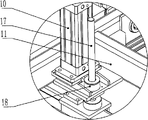
Fig. 2 is the partial enlarged drawing of A among Fig. 1.
Fig. 3 is the partial enlarged drawing of B among Fig. 1.
Fig. 4 is a partial structurtes schematic diagram of the present invention among Fig. 1.
Fig. 5 is a planar structure schematic diagram of the present invention.
Fig. 6 is a sucker partitioned organization schematic diagram.
Fig. 7 is another structural representation of synchronization lifting mechanism.
Fig. 8 is the two rod cylinder operation schematic diagrams of two-pass.
Wherein, 1 reducing motor, 2 blanking pins, 3 material blocking rods, 4 suckers, 5 suction cup carrier, 6 gears, 7 crossbeams, 8 tooth bars, 9 connectors, 10 lift cylinders, 11 bracing frames, 12 power transmission shafts, 13 guide rail slide block mechanisms, 14 slide blocks, 15 line slideways, 16 recesses, 17 guiding polished rods, 18 super bearings, 19 pusher cylinders, 20 floating junctions, 21 driving wheels, 22 chains, 23 threaded rods, 24 sprocket wheels, 25 regulating wheels.
The specific embodiment
Shown in Fig. 1-5, be laser-cutting automatic loading and unloading manipulator, comprise the latticed suction cup carrier 5 that is welded by channel-section steel, suction cup carrier 5 downsides are provided with some suckers 4, according to the size of sheet material to be processed, sucker 4 can be as shown in Figure 6, be divided into three districts,, can realize zones of different work by air valve corresponding to the plate of different size, suction cup carrier 5 tops are provided with the bracing frame 11 that can link to each other with the feed mechanism of lathe, and bracing frame 11 is provided with the elevating mechanism that drives suction cup carrier 5 elevating movements; Also be provided with reducing motor 1 on the bracing frame 11, the middle part of power transmission shaft 12 and reducing motor 1 are in transmission connection, power transmission shaft 12 is installed on the bracing frame 11 through bearing, power transmission shaft 12 two ends are respectively equipped with gear 6, the upper and lower sides of each gear 6 is meshed with a tooth bar 8 respectively, tooth bar 8 is arranged on four crossbeams that parallel 7, link to each other through guide rail slide block mechanism 13 between crossbeam 7 and the bracing frame 11, be positioned at the outer end of two crossbeams 7 of gear 6 downsides and the outer end that is positioned at two crossbeams 7 of gear 6 upsides and be connected with a horizontally disposed blanking fork separately, two blanking vents are in same level height position, and two blankings fork phase near-end upside is respectively equipped with material blocking rod 3; Blanking fork is arranged in parallel by some blanking pins 2 and its root is fixed on the connector 9 and forms; The end of the blanking pin 2 of two blankings fork is provided with in opposite directions, and material blocking rod 3 is provided with some recesses 16, and blanking pin 2 interts in the corresponding recess 16; Material blocking rod 3 is connected through slide block 14 with line slideway 15 on being installed in respective girders 7, and bracing frame 11 is provided with pusher cylinder 19, is connected through floating junction 20 between pusher cylinder 19 and the slide block 14; Pusher cylinder 19 is the two rod cylinders of two-pass as shown in Figure 8, and the piston rod external part of an end of pusher cylinder 19 links to each other with bracing frame 11, and the piston rod external part of the other end of pusher cylinder 19 links to each other with floating junction 20.Described elevating mechanism comprises rectangular arrangement and upright four lift cylinders 10 that are provided with, be provided with four super bearings 18 with lift cylinder 10 is corresponding one by one on the bracing frame 11, super bearing 18 is a prior art of the prior art, when it bears unbalance loading, can do the adaptability servo-actuated, cooperate in the super bearing 18 to be provided with upright guiding polished rod 17, guiding polished rod 17 lower ends link to each other with suction cup carrier 5, and the piston-rod lower end of lift cylinder 10 is provided with floating junction 20 in addition and links to each other with suction cup carrier 5.
During this device work, lift cylinder 10 can drive suction cup carrier 5 and move up and down, sucker 4 can pick up plate and put down, feed mechanism drives bracing frame 11 motions, plate can be moved to operating position, and sucker 4 is placed on plate on the workbench, realize material loading, behind the material loading, feed mechanism can be removed whole device, so that processing, after machining, can once more whole device be moved to operating position by feed mechanism, the blanking vent is in the outside of waste material, and reducing motor 1 driven gear 6 rotates, driving crossbeam 7 is synchronized with the movement, make blanking fork move toward one another, waste material is picked up, then, feed mechanism moves to the blanking position, by reducing motor 1 the blanking fork is opened once more, waste material falls, and realizes discharging.Plate can be piled up neatly by the pusher cylinder.
The present invention is not limited to said structure, described elevating mechanism can also be as shown in Figure 7, comprise four sprocket wheels 24 that are arranged on rotationally on the bracing frame 11, four sprocket wheel 24 rectangular distributions, installed around chain 22 between the sprocket wheel 24, described chain 22 also with bracing frame 11 on the driving wheel 21 that is provided be connected with regulating wheel 25, the be threaded threaded rod 23 of upright setting of each sprocket wheel 24 center, threaded rod 23 lower ends link to each other with suction cup carrier 5.
Multinomial functions such as material loading, blanking, backgauge, pusher that this device is compound, synchronization telescope is pitched in its automaticity height, blanking, suction cup carrier 5 liftings are synchronous, working stability is reliable.
Claims (4)
1. laser-cutting automatic loading and unloading manipulator comprises latticed suction cup carrier, and the suction cup carrier downside is provided with some suckers, and the suction cup carrier top is provided with the bracing frame that links to each other with the feed mechanism of lathe, and bracing frame is provided with the elevating mechanism that drives the suction cup carrier elevating movement; It is characterized in that: also be provided with reducing motor on the support frame as described above, the middle part and the reducing motor of power transmission shaft are in transmission connection, power transmission shaft is installed on the bracing frame through bearing, the power transmission shaft two ends are respectively equipped with gear, the upper and lower sides of each gear is meshed with a tooth bar respectively, described tooth bar is arranged on four crossbeams that parallel, link to each other through the guide rail slide block mechanism between described crossbeam and the bracing frame, be positioned at the outer end of two crossbeams of gear downside and the outer end that is positioned at two crossbeams of gear upside and be connected with a horizontally disposed blanking fork separately, two blanking vents are in same level height position, and described two blankings fork phase near-end upside is respectively equipped with material blocking rod; Described material blocking rod is connected through slide block with line slideway on being installed in respective girders, and bracing frame is provided with the pusher cylinder, is connected through floating junction between pusher cylinder and the slide block; Described pusher cylinder is the two rod cylinders of two-pass, and the piston rod external part of an end of pusher cylinder links to each other with bracing frame, and the piston rod external part of the other end of pusher cylinder links to each other with described floating junction.
2. laser-cutting automatic loading and unloading manipulator according to claim 1 is characterized in that: described blanking fork is arranged in parallel by some blanking pins and its root is fixed on the connector and forms; The end of the blanking pin of two blankings fork is provided with in opposite directions, and described material blocking rod is provided with some recesses, and the blanking pin interts in the corresponding recess.
3. laser-cutting automatic loading and unloading manipulator according to claim 1, it is characterized in that: described elevating mechanism comprises rectangular arrangement and upright four lift cylinders that are provided with, be provided with four super bearings with lift cylinder is corresponding one by one on the bracing frame, cooperate in the super bearing and be provided with upright guiding polished rod, guiding polished rod lower end links to each other with suction cup carrier, and the piston-rod lower end of lift cylinder is provided with floating junction in addition and links to each other with suction cup carrier.
4. laser-cutting automatic loading and unloading manipulator according to claim 1, it is characterized in that: described elevating mechanism comprises four sprocket wheels that are arranged on rotationally on the bracing frame, four rectangular distributions of sprocket wheel, installed around chain between the sprocket wheel, described chain also with bracing frame on the driving wheel that is provided be connected with regulating wheel, the be threaded threaded rod of upright setting of each centre of sprocket, the threaded rod lower end links to each other with suction cup carrier.
Priority Applications (1)
| Application Number | Priority Date | Filing Date | Title |
|---|---|---|---|
| CN 200910184072 CN101628362B (en) | 2009-08-13 | 2009-08-13 | Laser-cutting automatic loading and unloading manipulator |
Applications Claiming Priority (1)
| Application Number | Priority Date | Filing Date | Title |
|---|---|---|---|
| CN 200910184072 CN101628362B (en) | 2009-08-13 | 2009-08-13 | Laser-cutting automatic loading and unloading manipulator |
Publications (2)
| Publication Number | Publication Date |
|---|---|
| CN101628362A CN101628362A (en) | 2010-01-20 |
| CN101628362B true CN101628362B (en) | 2011-10-19 |
Family
ID=41573733
Family Applications (1)
| Application Number | Title | Priority Date | Filing Date |
|---|---|---|---|
| CN 200910184072 Active CN101628362B (en) | 2009-08-13 | 2009-08-13 | Laser-cutting automatic loading and unloading manipulator |
Country Status (1)
| Country | Link |
|---|---|
| CN (1) | CN101628362B (en) |
Families Citing this family (40)
| Publication number | Priority date | Publication date | Assignee | Title |
|---|---|---|---|---|
| CN102114513B (en) * | 2010-12-09 | 2013-01-09 | 江苏金方圆数控机床有限公司 | High-speed feeding mechanism |
| CN102218602A (en) * | 2011-03-30 | 2011-10-19 | 无锡华联精工机械有限公司 | Laser cutting machine worktable main frame body |
| CN102189553B (en) * | 2011-05-18 | 2013-08-07 | 奇瑞汽车股份有限公司 | Manipulator control system and control method |
| CN102500931B (en) * | 2011-11-15 | 2015-04-22 | 深圳市光大激光科技股份有限公司 | Automatic feeding and discharging laser cutting machine |
| CN102490175A (en) * | 2011-11-19 | 2012-06-13 | 扬州锻压机床集团有限公司 | Manipulator conveying device mechanism |
| CN103144348A (en) * | 2011-12-06 | 2013-06-12 | 东莞市天翔自动化设备有限公司 | A fully automatic punching machine |
| CN102658432A (en) * | 2012-05-18 | 2012-09-12 | 句容市大华激光科技开发有限公司 | Laser marking and cutting dual-purpose machine |
| CN102756933B (en) * | 2012-07-26 | 2015-03-25 | 无锡澳美机械有限公司 | Sheet conveying device |
| CN102923458A (en) * | 2012-11-23 | 2013-02-13 | 烟台孚瑞克森汽车部件有限公司 | Automatic brake block discharging and conveying line |
| CN103056532B (en) * | 2013-01-22 | 2015-05-20 | 大族激光科技产业集团股份有限公司 | Laser cutter standalone automatic feeding and discharging device and laser cutter standalone automatic feeding and discharging method |
| CN103600171B (en) * | 2013-04-28 | 2015-12-09 | 宝山钢铁股份有限公司 | The method and system of a kind of metallic plate loading and unloading and cutting |
| CN103600173B (en) * | 2013-04-28 | 2015-12-09 | 宝山钢铁股份有限公司 | The method of the fast platform cutting of a kind of two station and system thereof |
| CN103863855B (en) * | 2014-03-04 | 2017-02-22 | 绍兴县瑞群纺织机械科技有限公司 | Material distributing automatic taking and placing device |
| CN103962736B (en) * | 2014-05-22 | 2016-02-03 | 江苏金方圆数控机床有限公司 | Laser cutting sheet material waste material is separated and componentselected system |
| CN104175008B (en) * | 2014-08-19 | 2016-04-06 | 深圳雷柏科技股份有限公司 | A kind ofly adopt the radium-shine equipment of robot and radium-shine method |
| CN105016103A (en) * | 2014-08-27 | 2015-11-04 | 东莞市佳的自动化设备科技有限公司 | A material receiving mechanism and a material receiving method of a fully automatic pole piece laser cutting forming machine |
| CN106312874B (en) * | 2015-06-25 | 2018-05-22 | 江苏银环新能源科技有限公司 | Double glass Rimless components hook automatic assembling apparatus |
| CN105345831A (en) * | 2015-12-18 | 2016-02-24 | 苏州金逸康自动化设备有限公司 | Adsorption manipulator for link-type feeding assembly line |
| CN105855979B (en) * | 2016-05-19 | 2018-01-12 | 吉林省欣冉机械电子设备制造有限公司 | Intelligent workpiece processing equipment |
| CN106584435A (en) * | 2016-12-29 | 2017-04-26 | 安徽智森电子科技有限公司 | Automatic feeding manipulator mechanism |
| CN106994565B (en) * | 2017-05-27 | 2018-08-03 | 扬州恒佳自动化设备有限公司 | A kind of compact handling equipment |
| CN108326443A (en) * | 2017-05-27 | 2018-07-27 | 扬州恒佳自动化设备有限公司 | A kind of handling equipment of laser cutting machine band sorting function |
| CN107088711A (en) * | 2017-05-27 | 2017-08-25 | 扬州恒佳自动化设备有限公司 | A kind of laser cutting machine handling equipment |
| CN107097003A (en) * | 2017-05-27 | 2017-08-29 | 扬州恒佳自动化设备有限公司 | A kind of laser cutting machine loading and unloading robot |
| CN107934543B (en) * | 2017-12-19 | 2023-07-21 | 安徽省华夏机床制造有限公司 | A frame type sheet material conveying equipment |
| CN107877005B (en) * | 2017-12-24 | 2023-05-30 | 安徽工程大学 | Automatic bobbin cutting device and cutting method thereof |
| CN108637543B (en) * | 2018-06-05 | 2023-07-04 | 洛阳市优能自动化设备有限公司 | Full-automatic row welding machine device |
| CN108406146B (en) * | 2018-06-13 | 2024-04-30 | 湖北易同科技发展有限公司 | Manipulator for laser processing two-dimensional code automation line |
| CN109192043A (en) * | 2018-08-16 | 2019-01-11 | 合肥永屹智能制造职业培训学校 | A kind of multi-functional training platform of robot debugging |
| CN108867012A (en) * | 2018-09-13 | 2018-11-23 | 常州市新创智能科技有限公司 | A kind of multistation, which is cut, inhales cloth machine |
| CN110052741A (en) * | 2018-11-22 | 2019-07-26 | 襄阳东昇机械有限公司 | Automatic dotting device |
| CN109664033B (en) * | 2019-01-24 | 2024-03-22 | 苏州迅镭激光科技有限公司 | Automatic feeding and discharging device of laser cutting machine |
| CN110509304B (en) * | 2019-07-30 | 2021-02-02 | 安徽纳赫智能科技有限公司 | Combined end pick-up |
| CN111195785A (en) * | 2020-03-25 | 2020-05-26 | 扬州恒佳自动化设备有限公司 | Laser prong prevents fish tail device |
| CN112207854B (en) * | 2020-08-27 | 2021-10-15 | 南京市晨枭软件技术有限公司 | A composite clamp for industrial robot gripping |
| CN112192060B (en) * | 2020-10-08 | 2024-12-13 | 浙江金澳兰机床有限公司 | Wide range of applications Unloading structure with lifting and flipping functions |
| CN113523498B (en) * | 2021-07-13 | 2022-06-28 | 深圳市芯宇达电子有限公司 | Spot welding equipment is got with getting fast in electron device production |
| CN115229073B (en) * | 2022-07-22 | 2024-12-06 | 江苏金方圆数控机床有限公司 | A sheet material sorting and stacking device for punching and shearing composite machine |
| CN118650315B (en) * | 2024-08-12 | 2024-12-13 | 奔腾激光(浙江)股份有限公司扬州分公司 | A basic loading and unloading device for laser cutting machine |
| CN120644820B (en) * | 2025-07-02 | 2026-04-07 | 河南诺信腾达电子科技有限公司 | A laser cutting device for battery box processing |
-
2009
- 2009-08-13 CN CN 200910184072 patent/CN101628362B/en active Active
Also Published As
| Publication number | Publication date |
|---|---|
| CN101628362A (en) | 2010-01-20 |
Similar Documents
| Publication | Publication Date | Title |
|---|---|---|
| CN101628362B (en) | Laser-cutting automatic loading and unloading manipulator | |
| CN102114604B (en) | A kind of automatic loading and unloading device of sheet processing equipment | |
| CN201931321U (en) | Automatic feeding and discharging device of sheet processing equipment | |
| CN107902356A (en) | A kind of full-automatic material transport system | |
| CN219990457U (en) | Double-layer feeding conveying line | |
| CN203031607U (en) | Truss mechanical hand structure | |
| CN107097003A (en) | A kind of laser cutting machine loading and unloading robot | |
| CN104759935B (en) | Multi-station sheet conveying device | |
| CN201493616U (en) | Laser cutting automatic charging and blanking manipulator | |
| CN104773337A (en) | Snatch formula tray automatic distribution device | |
| CN212705774U (en) | Laser cutting and bending composite production line | |
| CN204110812U (en) | Skid conveying automatic turning-back type equipment | |
| CN206218814U (en) | A kind of file charging and discharging mechanism | |
| CN203865616U (en) | Automatic stacking mechanism for cargo truck loading | |
| CN203845377U (en) | Laser cutting flexible manufacture system | |
| CN205257309U (en) | Be used for fork welded fork automatic handling device | |
| CN204953724U (en) | Punching press lathe continuous production line | |
| CN105945286A (en) | Automatic material conveying device | |
| CN203359548U (en) | Tire carrying and stack dismantling system | |
| CN218968242U (en) | Bag stacking machine capable of replacing tray | |
| CN215247913U (en) | Automatic feeding bin for red cutting | |
| CN220160594U (en) | Part sorting system | |
| CN218319257U (en) | Circulation device for circulation of materials of turnover box | |
| CN103506886A (en) | Automatic feeding device | |
| CN211034376U (en) | Angle steel feeding mechanism |
Legal Events
| Date | Code | Title | Description |
|---|---|---|---|
| C06 | Publication | ||
| PB01 | Publication | ||
| C10 | Entry into substantive examination | ||
| SE01 | Entry into force of request for substantive examination | ||
| C14 | Grant of patent or utility model | ||
| GR01 | Patent grant |