BR112017000370B1 - DUAL TYPE TENSION WAVE GEAR - Google Patents
DUAL TYPE TENSION WAVE GEAR Download PDFInfo
- Publication number
- BR112017000370B1 BR112017000370B1 BR112017000370-8A BR112017000370A BR112017000370B1 BR 112017000370 B1 BR112017000370 B1 BR 112017000370B1 BR 112017000370 A BR112017000370 A BR 112017000370A BR 112017000370 B1 BR112017000370 B1 BR 112017000370B1
- Authority
- BR
- Brazil
- Prior art keywords
- teeth
- toothed gear
- internally toothed
- gear
- wave
- Prior art date
Links
Images


Classifications
-
- F—MECHANICAL ENGINEERING; LIGHTING; HEATING; WEAPONS; BLASTING
- F16—ENGINEERING ELEMENTS AND UNITS; GENERAL MEASURES FOR PRODUCING AND MAINTAINING EFFECTIVE FUNCTIONING OF MACHINES OR INSTALLATIONS; THERMAL INSULATION IN GENERAL
- F16H—GEARING
- F16H49/00—Other gearings
- F16H49/001—Wave gearings, e.g. harmonic drive transmissions
-
- F—MECHANICAL ENGINEERING; LIGHTING; HEATING; WEAPONS; BLASTING
- F16—ENGINEERING ELEMENTS AND UNITS; GENERAL MEASURES FOR PRODUCING AND MAINTAINING EFFECTIVE FUNCTIONING OF MACHINES OR INSTALLATIONS; THERMAL INSULATION IN GENERAL
- F16H—GEARING
- F16H1/00—Toothed gearings for conveying rotary motion
- F16H1/28—Toothed gearings for conveying rotary motion with gears having orbital motion
- F16H1/32—Toothed gearings for conveying rotary motion with gears having orbital motion in which the central axis of the gearing lies inside the periphery of an orbital gear
-
- F—MECHANICAL ENGINEERING; LIGHTING; HEATING; WEAPONS; BLASTING
- F16—ENGINEERING ELEMENTS AND UNITS; GENERAL MEASURES FOR PRODUCING AND MAINTAINING EFFECTIVE FUNCTIONING OF MACHINES OR INSTALLATIONS; THERMAL INSULATION IN GENERAL
- F16H—GEARING
- F16H49/00—Other gearings
- F16H49/001—Wave gearings, e.g. harmonic drive transmissions
- F16H2049/003—Features of the flexsplines therefor
Abstract
Trata-se de uma engrenagem externamente dentada (4) de uma engrenagem com onda de tensão do tipo duplo (1) dotada de primeiros e segundos dentes externos (7, 8) que têm diferentes números de dentes, e é flexionada em um formato de elipse por um gerador de onda. Quando os valores teóricos (d1, d2) das quantidades de flexão radial em posições de eixo geométrico principal dos primeiros e segundos dentes externos (7, 8) flexionados no formato de elipse são expressados por d1=m1n1 e d2=m2n2 (m1 e m2 representam os módulos dos primeiros e dos segundos dentes externos, e n1 e n2 representam números inteiros positivos), as quantidades de flexão radial (d1a, d2a) dos primeiros e dos segundos dentes externos (7, 8) flexionados pelo gerador de onda (5) satisfazem d1a=ód1 e d2a= ód2, em que 1,25 óóó3. Consequentemente, uma engrenagem com onda de tensão do tipo duplo pode ser alcançada com a qual os primeiros e os segundos dentes externos que têm diferentes números podem ser adequadamente flexionados para formar excelentes estados de correlação com respectivas engrenagens internamente dentadas.It is an externally toothed gear (4) of a double-type stress wave gear (1) having first and second external teeth (7, 8) having different numbers of teeth, and is bent into a ellipse by a wave generator. When the theoretical values (d1, d2) of the amounts of radial flexion at major axis positions of the first and second external teeth (7, 8) flexed in the ellipse shape are expressed by d1=m1n1 and d2=m2n2 (m1 and m2 represent the modules of the first and second external teeth, and n1 and n2 represent positive integers), the amounts of radial flexion (d1a, d2a) of the first and second external teeth (7, 8) flexed by the wave generator (5 ) satisfy d1a=ód1 and d2a=ód2, where 1.25 óóó3. Consequently, a double-type stress wave gear can be achieved with which the first and second outer teeth having different numbers can be suitably flexed to form excellent correlation states with respective internally toothed gears.
Description
[0001] A presente invenção refere-se a uma engrenagem com onda de tensão que tem um par de engrenagens internamente dentadas, uma engrenagem externamente dentada cilíndrica com capacidade de se flexionar em uma direção radial, e um gerador de onda.[0001] The present invention relates to a voltage wave gear having a pair of internally toothed gears, a cylindrical externally toothed gear capable of flexing in a radial direction, and a wave generator.
[0002] As engrenagens com onda de tensão que têm engrenagens externamente dentadas cilíndricas são tipicamente dotadas de uma engrenagem internamente dentada de lado estacionário presa com a finalidade de não girar, um gerador de onda que é um elemento de inserção de rotação, uma engrenagem internamente dentada de lado de acionamento que é um elemento de emissão de rotação reduzida, e uma engrenagem externamente dentada cilíndrica com capacidade de se flexionar na direção radial e entrelaçar com a engrenagem internamente dentada de lado estacionário e a engrenagem internamente dentada de lado de acionamento. Em engrenagens com onda de tensão típicas, a engrenagem externamente dentada é provocada a se flexionar em um formato de elipse, em que engrenagem externamente dentada flexionada em formato de elipse entrelaça com as engrenagens internamente dentadas de lado de acionamento e de lado estacionário em ambas as posições de extremidade ao longo do eixo geométrico principal do formato de elipse.[0002] Stress wave gears that have cylindrical external toothed gears are typically provided with an internally toothed stationary-side gear attached for non-turning purposes, a wave generator that is a rotation insert element, an internally geared drive side gear which is a low speed emitting element, and a cylindrical externally toothed gear capable of flexing in the radial direction and meshing with the stationary side internally toothed gear and the driving side internally toothed gear. In typical stress wave gears, the externally toothed gear is caused to flex into an elliptical shape, where the externally toothed gear flexed into an ellipse meshes with the driving-side and stationary-side internally toothed gears on both sides. endpoint positions along the major axis of the ellipse shape.
[0003] O Documento de Patente 1 revela uma engrenagem com onda de tensão típica na qual o número de dentes da engrenagem internamente dentada de lado estacionário é duas vezes maior do que o da engrenagem externamente dentada, e o número de dentes da engrenagem internamente dentada de lado de acionamento é igual ao da engrenagem externamente dentada. Os dentes externos da engrenagem externamente dentada são bisseccionados na porção central de direção de traço de dente dos mesmos, em que uma das porções de dente externo tem capacidade de entrelaçar com a engrenagem internamente dentada de lado estacionário, e a outra das porções de dente externo tem capacidade de entrelaçar com a engrenagem internamente dentada de lado de acionamento. Quando o gerador de onda gira, a engrenagem externamente dentada é girada a uma razão de velocidade de acordo com a diferença em número de dentes entre a engrenagem externamente dentada e a engrenagem internamente dentada de lado estacionário. A rotação de velocidade reduzida da engrenagem externamente dentada é emitida a partir da engrenagem internamente dentada de lado de acionamento, que gira integralmente com a engrenagem externamente dentada.[0003]
[0004] O Documento de Patente 2 revela uma engrenagem com onda de tensão na qual o número de dentes da engrenagem internamente dentada de lado estacionário é duas vezes maior que o da engrenagem externamente dentada, e o número de dentes da engrenagem internamente dentada de lado de acionamento é duas vezes menor que o da engrenagem externamente dentada. Nessa engrenagem com onda de tensão, quando o gerador de onda gira, a engrenagem externamente dentada gira mais lentamente em uma razão de velocidade que corresponde à diferença no número de dentes em relação à engrenagem internamente dentada de lado estacionário. A rotação da engrenagem externamente dentada é aumentada em uma razão de velocidade que corresponde à diferença em número e dentes entre a engrenagem externamente dentada e a engrenagem internamente dentada de lado de acionamento, e é emitida a partir da engrenagem internamente dentada de lado de acionamento. A rotação emitida a partir da engrenagem internamente dentada de lado de acionamento é reduzida a uma razão de velocidade de menos que 50 em relação à rotação inserida no gerador de onda.[0004]
[0005] Os Documentos de Patente 2 e 3 revelam engrenagens com onda de tensão que têm geradores de onda que têm duas fileiras de mancais esféricos. Esse tipo de gerador de onda é configurado a partir de um plugue rígido que tem uma superfície periférica externa de contorno em elipse, e duas fileiras de mancais esféricos encaixados na superfície periférica externa. A engrenagem internamente dentada flexível é pressionada radialmente para fora pelas duas porções de extremidade de eixo geométrico principal das superfícies periféricas externas dos traços externos flexionados em forma de elipse dos mancais esféricos, e o entrelaçamento da engrenagem internamente dentada flexível em relação às primeira e segunda engrenagens internamente dentadas rígidas é sustentado.[0005]
[0006] Documento de Patente 1: JP-A 2011-112214[0006] Patent Document 1: JP-A 2011-112214
[0007] Documento de Patente 2: JP-A 02-275147[0007] Patent Document 2: JP-A 02-275147
[0008] Documento de Patente 3: JP-U01-91151[0008] Patent Document 3: JP-U01-91151
[0009] Considera-se que, na engrenagem externamente dentada usada no presente documento, os primeiros dentes com capacidade de entrelaçar com uma primeira engrenagem internamente dentada e os segundos dentes com capacidade de entrelaçar com uma outra segunda engrenagem internamente dentada são formados na superfície periférica externa de um corpo cilíndrico radialmente flexível, em que os segundos dentes diferem em número dos primeiros dentes. A adoção de tal configuração torna possível realizar uma engrenagem com onda de tensão que tem uma razão de engrenagem menor que 50 de uma maneira similar como na engrenagem com onda de tensão revelada no Documento de Patente 2. Adicionalmente, essa configuração permite que uma engrenagem com onda de tensão que tem uma razão de velocidade menor que 50 seja projetada com um grau de liberdade maior do que na engrenagem com onda de tensão revelada do Documento de Patente 2.[0009] It is considered that, in the externally toothed gear used in the present document, the first teeth capable of meshing with a first internally toothed gear and the second teeth capable of meshing with another second internally toothed gear are formed on the peripheral surface external part of a radially flexible cylindrical body, in which the second teeth differ in number from the first teeth. The adoption of such a configuration makes it possible to realize a stress wave gear having a gear ratio less than 50 in a similar manner as in the stress wave gear disclosed in
[0010] No presente relatório descritivo, uma engrenagem com onda de tensão que tem uma engrenagem externamente dentada na qual os primeiros e segundos dentes externos diferem em número são formados na superfície periférica externa de um corpo cilíndrico flexível é chamada de "engrenagem com onda de tensão de tipo duplo".[0010] In the present specification, a stress wave gear having an externally toothed gear in which the first and second external teeth differ in number are formed on the outer peripheral surface of a flexible cylindrical body is called a "stress wave gear". dual-type voltage".
[0011] Em uma engrenagem com onda de tensão de tipo duplo, os primeiros dentes externos e os segundos dentes externos de uma engrenagem externamente dentada são formados na superfície periférica externa de um corpo cilíndrico compartilhado, e as partes de aro de fundo de dente dos primeiros e dos segundos dentes externos são conectadas entre si. Quando o corpo cilíndrico é provocado pelo gerador de onda a flexionar em um formato de elipse, os primeiros e segundos dentes externos, que diferem em número, respectivamente, se entrelaçam com engrenagens internamente dentadas.[0011] In a double-type stress wave gear, the first outer teeth and the second outer teeth of an externally toothed gear are formed on the outer peripheral surface of a shared cylindrical body, and the tooth bottom rim parts of the first and second outer teeth are connected to each other. When the cylindrical body is caused by the wave generator to flex into an elliptical shape, the first and second outer teeth, which differ in number respectively, interlock with internally toothed gears.
[0012] A determinação da quantidade de flexão de cada um desses dentes externos tem um efeito maior do estado de entrelaçamento, resistência a desgaste e resistência à fadiga de aro de dente de cada um dos dentes externos. Adicionalmente, o estado de flexão de cada um dos dentes externos tem um efeito maior na distribuição de carga de esfera de cada um dos mancais de onda do gerador de onda, em que os mancais de onda sustentam os primeiros e os segundos dentes externos, respectivamente. Isso também tem efeito sobre a vida útil desses mancais de onda.[0012] Determining the amount of bending of each of these outer teeth has a greater effect on the interlacing state, wear resistance, and tooth rim fatigue strength of each of the outer teeth. Additionally, the state of flexion of each of the outer teeth has a major effect on the ball load distribution of each of the wave generator's wave bearings, where the wave bearings support the first and second outer teeth, respectively. . This also has an effect on the service life of these wave bearings.
[0013] Quando os primeiros e os segundos dentes externos são formados em engrenagens separadas, as respectivas engrenagens podem ser flexionadas em formato de elipse com a finalidade de ter uma quantidade de flexão adequada para cada engrenagem. Através disso é possível que os primeiros e os segundos dentes externos se entrelacem com os dentes internos correspondentes em um estado de entrelaçamento adequado.[0013] When the first and second outer teeth are formed in separate gears, the respective gears can be bent in an ellipse shape in order to have a suitable amount of bending for each gear. Through this it is possible for the first and second outer teeth to interlock with the corresponding inner teeth in a proper interlocking state.
[0014] Entretanto, quando a engrenagem com onda de tensão do tipo duplo é considerada, uma vez que os primeiros e os segundos dentes externos são formados em um corpo cilíndrico compartilhado, os mesmos não podem ser flexionados separadamente por diferentes quantidades de flexão de acordo com os números desses dentes externos. Adicionalmente, quando o corpo cilíndrico é provocado a flexionar por uma quantidade de flexão adequada para os dentes externos, não é possível em alguns casos manter o estado de entrelaçamento dos outros dentes externos em um estado apropriado. Adicionalmente, uma vez um dos estados de entrelaçamento dos primeiros e segundos dentes externos tem um efeito sobre outro dentre os estados de entrelaçamentos dos mesmos, cada um dos dentes externos não pode flexionar em um estado apropriado se a interação mútua entre os estados de entrelaçamento desses dentes externos não for considerada.[0014] However, when the double-type stress wave gear is considered, since the first and second outer teeth are formed in a shared cylindrical body, they cannot be flexed separately by different amounts of flexing according to with the numbers of these outer teeth. Additionally, when the cylindrical body is caused to flex by an adequate amount of flexion for the outer teeth, it is not possible in some cases to maintain the interlocking state of the other outer teeth in a proper state. Additionally, since one of the entanglement states of the first and second outer teeth has an effect on another of the entanglement states thereof, each of the outer teeth cannot flex into an appropriate state if the mutual interaction between the entanglement states of those external teeth is not considered.
[0015] Em vista das desvantagens descritas acima, um objetivo da presente invenção consiste em fornecer uma engrenagem com onda de tensão do tipo duplo na qual os primeiros e os segundos dentes externos têm diferentes números de dente podem ser flexionados apropriadamente para formar estados de entrelaçamento adequados em relação às respectivas engrenagens internamente dentadas.[0015] In view of the disadvantages described above, an object of the present invention is to provide a double-type stress wave gear in which the first and second outer teeth having different numbers of teeth can be flexed appropriately to form interlocking states suitable in relation to the respective internally toothed gears.
[0016] Um outro objetivo da presente invenção consiste em fornecer uma engrenagem com onda de tensão do tipo duplo na qual é possível ponderar a distribuição de carga de esfera de mancal do mancal de onda do gerador de onda para que sustenta os primeiros e os segundos dentes externos ao flexionar os primeiros e os segundos dentes externos com diferentes números de dente de uma maneira adequada.[0016] Another object of the present invention is to provide a double-type voltage wave gear in which it is possible to weight the bearing ball load distribution of the wave generator wave bearing so that it sustains the first and second outer teeth by flexing the first and second outer teeth with different numbers of teeth in a suitable manner.
[0017] A fim de solucionar o problema descrito acima, uma engrenagem com onda de tensão de tipo duplo da presente invenção é caracterizada por incluir:[0017] In order to solve the problem described above, a dual-type voltage wave gear of the present invention is characterized by including:
[0018] uma primeira engrenagem internamente dentada rígida na qual primeiros dentes internos são formados;[0018] a rigid first internally toothed gear on which first internal teeth are formed;
[0019] uma segunda engrenagem internamente dentada rígida na qual segundos dentes internos são formados, em que a segunda engrenagem internamente dentada é disposta com a finalidade de ser coaxialmente alinhada em paralelo com a primeira engrenagem internamente dentada;[0019] a rigid second internally toothed gear on which second internally toothed teeth are formed, wherein the second internally toothed gear is arranged for the purpose of being coaxially aligned in parallel with the first internally toothed gear;
[0020] uma engrenagem externamente dentada flexível na qual primeiros dentes externos com capacidade de entrelaçar com os primeiros dentes internos e os segundos dentes externos com capacidade de entrelaçar com os segundos dentes internos são formados na superfície periférica externa de um corpo cilíndrico radialmente flexível, em que os segundos dentes diferem em número dos primeiros dentes, e a engrenagem externamente dentada é disposta coaxialmente dentro da primeira e da segunda engrenagens internamente dentadas; e[0020] a flexible externally toothed gear in which first external teeth capable of interlocking with the first internal teeth and second external teeth capable of meshing with the second internal teeth are formed on the outer peripheral surface of a radially flexible cylindrical body, in that the second teeth differ in number from the first teeth, and the externally toothed gear is coaxially disposed within the first and second internally toothed gears; It is
[0021] um gerador de onda que faz com que a engrenagem externamente dentada se flexione em um formato de elipse, fazendo com que os primeiros dentes externos entrelacem parcialmente com os primeiros dentes internos e fazendo com que os segundos dentes externos entrelacem parcialmente com os segundos dentes internos;[0021] a wave generator that causes the externally toothed gear to flex in an elliptical shape, causing the first outer teeth to partially intertwine with the first inner teeth and causing the second outer teeth to partially intertwine with the second internal teeth;
[0022] em que, quando m1 é o módulo dos primeiros dentes externos, m2 é o módulo dos segundos dentes externos,[0022] where, when m1 is the module of the first external teeth, m2 is the module of the second external teeth,
[0023] n1 e n2 são números inteiros positivos, 2n1 é a diferença em número de dentes entre os primeiros dentes externos e os primeiros dentes internos, e 2n2 é a diferença em número de dentes entre os segundos dentes externos e os segundos dentes internos, e[0023] n1 and n2 are positive integers, 2n1 is the difference in number of teeth between the first outer teeth and the first inner teeth, and 2n2 is the difference in number of teeth between the second outer teeth and the second inner teeth, It is
[0024] o valor teórico d1 da quantidade pela qual os primeiros dentes externos são radialmente flexionados em posições de eixo geométrico principal e o valor teórico d2 da quantidade pela qual os segundos dentes externos são radialmente flexionados quando a engrenagem externamente flexionada é flexionada em um formato de elipse são respectivamente representados pelas relações
[0025] as quantidades d1a e d2a satisfazem as relações
[0026] em que d1a é uma quantidade pela qual os primeiros dentes externos são radialmente flexionados pelo gerador de onda, d2a é a quantidade pela qual os segundos dentes externos são radialmente flexionados pelo gerador de onda, e w é um coeficiente que tem um valor maior do que 1.[0026] where d1a is an amount by which the first outer teeth are flexed radially by the wave generator, d2a is the amount by which the second outer teeth are radially flexed by the wave generator, and w is a coefficient having a greater value than 1.
[0027] Em outras palavras, as quantidades de flexão radial d1a e d2a dos primeiros e segundos dentes externos são ambas definidas como maiores que seus valores teóricos d1 e d2, respectivamente. Mais especificamente, o formato de perfil do gerador de onda é definida de modo que os primeiros e os segundos dentes externos sejam flexionados por tais quantidades flexíveis.[0027] In other words, the radial flexion amounts d1a and d2a of the first and second external teeth are both defined as greater than their theoretical values d1 and d2, respectively. More specifically, the profile shape of the wave generator is defined so that the first and second outer teeth are flexed by such flexible amounts.
[0028] É preferencial que o valor do coeficiente w esteja dentro da seguinte faixa:
[0029] O círculo neutro de aro é o círculo que atravessa o centro de espessura do corpo cilíndrico (aro de fundo de dente) em um estado no qual a engrenagem externamente dentada é perfeitamente circular antes de ser flexionada em um formato de elipse. O círculo neutro de aro é deformado em um formato de elipse devido à engrenagem externamente dentada que é flexionada em um formato de elipse. Esse círculo deformado é chamado de "curva neutra de aro em formato de elipse". A quantidade pela qual a engrenagem externamente dentada é radialmente flexionada é a diferença entre o raio do eixo geométrico principal da curva neutra de aro em formato de elipse e o raio do círculo neutro de aro. Essa quantidade é representada por Kmn, em que m é o módulo da engrenagem externamente dentada, 2n é a diferença em número de dentes em relação às engrenagens internamente dentadas (n é um número positivo inteiro), e K é o coeficiente de deflexão. A quantidade mn de flexão radial quando K é igual a 1 é um valor obtido pela divisão do diâmetro de círculo de arfagem da engrenagem externamente dentada pela razão de redução de quando a engrenagem internamente dentada rígida é presa; esse é o valor teórico (quantidade de flexão em uma deflexão padrão) da quantidade de flexão radial.[0029] The rim neutral circle is the circle that passes through the center of thickness of the cylindrical body (tooth bottom rim) in a state in which the externally toothed gear is perfectly circular before being bent into an elliptical shape. The rim neutral circle is deformed into an ellipse shape due to the externally toothed gear that is bent into an ellipse shape. This deformed circle is called an "ellipse-shaped hoop neutral curve". The amount by which the externally toothed gear is radially flexed is the difference between the radius of the major axis of the ellipse-shaped rim neutral curve and the radius of the rim neutral circle. This quantity is represented by Kmn, where m is the module of the externally toothed gear, 2n is the difference in number of teeth relative to the internally toothed gears (n is a positive integer), and K is the coefficient of deflection. The amount mn of radial bending when K equals 1 is a value obtained by dividing the pitch circle diameter of the externally toothed gear by the reduction ratio when the rigid internally toothed gear is clamped; this is the theoretical value (amount of flex at a standard deflection) of the amount of radial flex.
[0030] Dessa forma, no caso dos primeiros e dos segundos dentes externos 7 e 8 que diferem em número e são formados na superfície periférica externa do mesmo corpo cilíndrico, os diâmetros de círculo de intervalos dos dentes em ambos os lados são aproximadamente iguais e, portanto, o valor teórico mn da quantidade de flexão radial é menor para os dentes externos que têm números de dente maiores.[0030] Thus, in the case of the first and second
[0031] Na presente invenção, as quantidades de flexão radial dos primeiros e dos segundos dentes externos que diferem em número são definidas como maiores que os valores teóricos (w>1) conforme descrito acima. Quando as quantidades de flexão dos primeiros e dos segundos dentes externos são definidas como maiores que os valores teóricos, ambos os dentes externos podem ser entrelaçados com os dentes internos, respectivamente, de uma maneira adequada, de modo que seja é possível melhorar a resistência a desgaste e a resistência à fadiga de fundo de dente dos primeiros e dos segundos dentes externos. Em particular, ao definir o valor de w conforme descrito acima, é possível estabelecer um estado de entrelaçamento adequado dos primeiros e dos segundos dentes externos, e a resistência a desgaste e resistência à fadiga de fundo de dente dos mesmos pode ser melhorada.[0031] In the present invention, the amounts of radial flexion of the first and second external teeth that differ in number are defined as greater than the theoretical values (w>1) as described above. When the bending amounts of the first and second outer teeth are set to greater than the theoretical values, both the outer teeth can be interlocked with the inner teeth, respectively, in a suitable manner, so that it is possible to improve the resistance to wear and resistance to tooth root fatigue of the first and second external teeth. In particular, by setting the value of w as described above, it is possible to establish a proper interlacing state of the first and second outer teeth, and the wear resistance and tooth bottom fatigue strength of them can be improved.
[0032] Em um caso em que o gerador de onda é dotado de duas fileiras de mancais de onda para sustentar os primeiros e os segundos dentes externos, é possível ponderar a distribuição de carga de esfera de mancal de cada um dos mancais de onda. Com isso, o tempo de vida dos mancais de onda pode ser prolongado.[0032] In a case where the wave generator is equipped with two rows of wave bearings to support the first and second external teeth, it is possible to weight the bearing ball load distribution of each of the wave bearings. As a result, the lifetime of wave bearings can be extended.
[0033] Na engrenagem com onda de tensão do tipo duplo da presente invenção, uma razão de velocidade R1 entre a primeira engrenagem internamente dentada e a engrenagem externamente dentada que tem primeiros dentes externos, uma razão de velocidade R2 entre a segunda engrenagem internamente dentada e a engrenagem externamente dentada que tem segundos dentes externos e uma razão de velocidade R da engrenagem com onda de tensão são respectivamente definidas da seguinte forma:
[0034] em que Zc1 é o número de dente dos primeiros dentes internos, Zc2 é o número de dente dos segundos dentes internos, Zf1 é o número de dente dos primeiros dentes externos, e Zf2 é o número de dente dos segundos dentes externos.[0034] where Zc1 is the tooth number of the first inner teeth, Zc2 is the tooth number of the second inner teeth, Zf1 is the tooth number of the outer first teeth, and Zf2 is the tooth number of the outer second teeth.
[0035] Consequentemente, é possível obter uma razão de velocidade menor do que 50, por exemplo, uma razão de velocidade apreciavelmente menor do que 30. Adicionalmente, diferentemente da técnica anterior, os primeiros dentes externos e os segundos dentes externos que diferem em número e módulo são formados como os dentes externos da engrenagem externamente dentada. Consequentemente, há um grau de liberdade maior no projeto para definir a razão de velocidade, e uma engrenagem com onda de tensão que tem uma razão de velocidade baixa pode ser realizada mais facilmente do que na técnica anterior.[0035] Consequently, it is possible to obtain a speed ratio of less than 50, for example, a speed ratio appreciably less than 30. Additionally, unlike the prior art, the first outer teeth and the second outer teeth differ in number and module are formed as the external teeth of the externally toothed gear. Consequently, there is a greater degree of freedom in the design to define the speed ratio, and a stress wave gear having a low speed ratio can be realized more easily than in the prior art.
[0036] Na engrenagem com onda de tensão de tipo duplo da presente invenção, o número Zf1 dos primeiros dentes externos difere do número Zc1 dos primeiros dentes internos, e o número Zf2 de segundos dentes externos difere do número Zc2 de segundos dentes internos. Por exemplo, o número Zf1 de primeiros dentes externos é menor que o número Zc1 de primeiros dentes internos, e o número Zc1 de primeiros dentes internos e o número Zc2 de segundos dentes internos são iguais entre si.[0036] In the dual-type stress wave gear of the present invention, the Zf1 number of the first outer teeth differs from the Zc1 number of the first inner teeth, and the Zf2 number of the second outer teeth differs from the Zc2 number of the second inner teeth. For example, the Zf1 number of first outer teeth is less than the Zc1 number of first inner teeth, and the Zc1 number of first inner teeth and Zc2 number of second inner teeth are equal to each other.
[0037] Além disso, o que gerador de onda é definido como um elemento de inserção de rotação; e uma dentre a primeira engrenagem internamente dentada e a segunda engrenagem internamente dentada é definida como uma engrenagem internamente dentada de lado estacionário presa com a finalidade de não girar, e a outra dentre a primeira engrenagem internamente dentada e a segunda engrenagem internamente dentada é uma engrenagem internamente dentada de lado de acionamento que é um elemento de emissão de rotação reduzida.[0037] Furthermore, what wave generator is defined as a rotating insert element; and one of the first internally toothed gear and the second internally toothed gear is defined as a stationary side internally toothed gear attached for the purpose of not rotating, and the other of the first internally toothed gear and the second internally toothed gear is a gear drive-side internally toothed gear that is a low-rev emission element.
[0038] A Figura 1 é uma vista de superfície de extremidade e uma vista em corte transversal longitudinal de uma engrenagem com onda de tensão de tipo duplo à qual a presente invenção é aplicada;[0038] Figure 1 is an end surface view and a longitudinal cross-sectional view of a dual-type stress wave gear to which the present invention is applied;
[0039] A Figura 2 é um diagrama esquemático da engrenagem com onda de tensão de tipo duplo mostrada na Figura 1;[0039] Figure 2 is a schematic diagram of the dual-type voltage wave gear shown in Figure 1;
[0040] A Figura 3 é uma vista em corte transversal parcial ampliada da engrenagem com onda de tensão mostrada na Figura 1;[0040] Figure 3 is an enlarged partial cross-sectional view of the voltage wave gear shown in Figure 1;
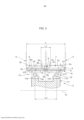
[0041] A Figura 4 é um diagrama que mostra o estado flexionado da engrenagem externamente dentada mostrada na Figura 1; e[0041] Figure 4 is a diagram showing the flexed state of the externally toothed gear shown in Figure 1; It is
[0042] Uma modalidade de uma engrenagem com onda de tensão de tipo duplo à qual a presente invenção é aplicada é descrita abaixo em referência aos desenhos anexos.[0042] One embodiment of a dual type stress wave gear to which the present invention is applied is described below with reference to the accompanying drawings.
[0043] A Figura 1(a) é uma vista de superfície de extremidade e uma vista em corte transversal longitudinal que mostram uma engrenagem com onda de tensão do tipo duplo (chamada abaixo simplesmente de "engrenagem com onda de tensão") de acordo com uma modalidade da presente invenção, e a Figura 1(b) é uma vista em corte transversal longitudinal que mostra uma porção cortada ao longo da linha b-b da Figura 1(a). A Figura 2 é um diagrama esquemático da mesma. A engrenagem com onda de tensão 1, que é usada como, por exemplo, um redutor de engrenagem, tem uma primeira engrenagem internamente dentada rígida anular 2, uma segunda engrenagem internamente dentada rígida anular 3, uma engrenagem internamente dentada flexível cilíndrica 4 que compreende um corpo elástico de parede fina radialmente flexível e um gerador de onda com contorno de elipse 5.[0043] Figure 1(a) is an end surface view and a longitudinal cross-sectional view showing a double-type stress wave gear (referred to below simply as "stress wave gear") in accordance with an embodiment of the present invention, and Figure 1(b) is a longitudinal cross-sectional view showing a portion cut along line b-b of Figure 1(a). Figure 2 is a schematic diagram thereof. The
[0044] A primeira e a segunda engrenagens internamente dentadas 2, 3 são dispostas com a finalidade de serem coaxialmente alinhadas em paralelo entre si, com um vão previsto entre as mesmas, ao longo da direção de um eixo geométrico central 1a. No presente exemplo, a primeira engrenagem internamente dentada 2 é uma engrenagem internamente dentada de lado estacionário presa com a finalidade de girar, o número de primeiros dentes internos 2a da mesma é indicado por Zc1. A segunda engrenagem internamente dentada 3 é uma engrenagem internamente dentada de lado de acionamento sustentada de modo giratório, o número de segundos dentes internos 3a da mesma é indicado por Zc2. A segunda engrenagem internamente dentada 3 é o elemento de emissão de rotação reduzida da engrenagem com onda de tensão 1.[0044] The first and second internally
[0045] A engrenagem externamente dentada cilíndrica 4 é disposta coaxialmente dentro da primeira e da segunda engrenagens internamente dentadas 2, 3. A engrenagem externamente dentada 4 tem um corpo cilíndrico 6 que é um corpo elástico de parede fina radialmente flexível, primeiros dentes externos 7 e segundos dentes externos 8 formados na superfície periférica externa circular do corpo cilíndrico 6, e um vão 9 (em referência à Figura 3) formado entre os dentes externos 7, 8 em cada lado, em que o vão 9 funciona como uma área de folga de cortador. Os primeiros dentes externos 7 são formados em um lado ao longo da direção do eixo geométrico central 1a da superfície periférica externa circular do corpo cilíndrico 6, e os segundos dentes externos 8 são formados no outro lado de segundo dentes internos 3a da superfície periférica externa circular. Os primeiros e os segundos dentes externos 7, 8 são formados de modo que a direção do eixo geométrico central 1a seja a direção de traço de dente.[0045] The cylindrical externally
[0046] Especificamente, os primeiros dentes externos 7 são formados no lado oposto aos primeiros dentes internos 2a, e têm capacidade de entrelaçar com os primeiros dentes internos 2a, o número de primeiros dentes externos 7 é indicado por Zf1. Os segundos dentes externos 8 são formados no lado oposto aos segundos dentes internos 3a, e têm capacidade de entrelaçar com os segundos dentes internos 3a, o número de segundos dentes externos 8 é indicado por Zf2. Os números Zf1, Zf2 de dentes são diferentes uns dos outros.[0046] Specifically, the first
[0047] O gerador de onda 5 tem um plugue rígido com formato de elipse 11, e um primeiro mancal de onda 12 e segundo mancal de onda 13, em que o primeiro e o segundo mancais de onda são encaixados na superfície periférica externa em formato de elipse do plugue rígido 11. O primeiro e o segundo mancais de onda 12, 13 são formados a partir de mancais esféricos.[0047] The
[0048] O gerador de onda 5 é inserido na superfície periférica interna do corpo cilíndrico 6 da engrenagem externamente dentada 4, e faz com que o corpo cilíndrico 6 se flexione em um formato de elipse. Portanto, os primeiros e os segundos dentes externos 7, 8 são também flexionados em um formato de elipse. A engrenagem externamente dentada flexionada em formato de elipse 4 entrelaça com a primeira e a segunda engrenagens internamente dentadas 2, 3 em ambas as posições de extremidade ao longo do eixo geométrico principal Lmax do formato de elipse. Especificamente, os primeiros dentes externos 7 se entrelaçam com os primeiros dentes internos 2a em ambas as posições de extremidade ao longo do eixo geométrico principal do formato de elipse, e os segundos dentes externos 8 se entrelaçam com os segundos dentes internos 3a em ambas as posições de extremidade ao longo do eixo geométrico principal.[0048] The
[0049] O gerador de onda 5 é o elemento de inserção de rotação da engrenagem com onda de tensão 1. O plugue rígido 11 do gerador de onda 5 tem um orifício de eixo 11c, no qual um eixo de rotação de entrada 10 (em referência à Figura 2) é conectado seguramente em uma disposição coaxial. Por exemplo, um eixo de saída de motor pode ser seguramente conectado em uma disposição coaxial no orifício de eixo 11c. Quando o gerador de onda 5 gira, as posições nas quais os primeiros dentes externos 7 da engrenagem externamente dentada 4 e os primeiros dentes internos de lado estacionário 2a se entrelaçam, e as posições nas quais os segundos dentes externos 8 da engrenagem externamente dentada 4 e os segundos dentes internos de lado de acionamento 3a se entrelaçam, se movem ao longo da direção circunferencial.[0049] The
[0050] O número Zf1 de primeiros dentes externos 7 e o número Zf2 de segundos dentes externos 8 diferem um do outro; no presente exemplo, o número Zf2 de segundos dentes externos é maior. O número Zc1 de primeiros dentes internos 2a e o número Zf1 de primeiros dentes externos 7 também diferem um do outro; no presente exemplo, o número Zc1 de primeiros dentes internos 2a é maior. O número Zc2 de segundos dentes internos 3a e o número Zf2 de segundos dentes externos 8 diferem um do outro; no presente exemplo, o número Zc2 de segundos dentes internos 3a é menor.[0050] The Zf1 number of first
[0051] No presente exemplo, a engrenagem externamente dentada 4 é provocada a flexionar em um formato de elipse, e entrelaça com as engrenagens internamente dentadas 2 e 3 em dois locais ao longo da direção circunferencial. Portanto, a diferença entre o número Zc1 de primeiros dentes internos 2a e o número Zf1 de primeiros dentes externos 7 é 2n1, em que n1 é um número inteiro positivo. A diferença entre o número Zc2 de segundos dentes internos 3a e o número Zf2 de segundos dentes externos 8 é 2n2, em que n2 é um número inteiro positivo. Zc1=Zf1+2n1 Zc2=Zf2-2n2[0051] In the present example, the externally
[0052] Em um exemplo específico, os números de dentes são definidos da seguinte forma (n1=n2=1): Zc1=62 Zf1=60 Zc2=62 Zf2=64[0052] In a specific example, the numbers of teeth are defined as follows (n1=n2=1): Zc1=62 Zf1=60 Zc2=62 Zf2=64
[0053] A razão de velocidade R1 entre a primeira engrenagem internamente dentada 2 e os primeiros dentes externos 7, e a razão de velocidade R2 entre a segunda engrenagem internamente dentada 3 e os segundos dentes externos 8, são respectivamente definidas da seguinte forma: i1=1/R1=(Zf1-Zc1)/Zf1=(60-62)/60=-1/30 i2=1/R2=(Zf2-Zc2)/Zf2=(64-62)/64=1/32[0053] The speed ratio R1 between the first internally
[0054] Portanto, R1=-30 e R2=32.[0054] Therefore, R1=-30 and R2=32.
[0055] A razão de velocidade R da engrenagem com onda de tensão 1 é representada pela seguinte fórmula com o uso das razões de velocidade R1 e R2. Dessa forma, de acordo com a presente invenção, uma engrenagem com onda de tensão que tem uma razão de velocidade dramaticamente baixa (razão de redução baixa) pode ser realizada (uma razão de velocidade negativa indica que a rotação de saída progride na direção oposta à da rotação de entrada). R=(R1xR2-R1)/(-R1+R2) =(-30x32+30)/(30+32) = -930/62 = -15[0055] The speed ratio R of the gear with
[0056] A Figura 3 é uma vista em corte transversal ampliada parcial da engrenagem com onda de tensão, que mostra a engrenagem externamente dentada 4 bem como o primeiro e o segundo mancais de onda 12 e 13 do gerador de onda 5. O vão 9 formado entre os primeiros e os segundos dentes externos 7 e 8 funciona como uma área de folga de cortador para cortadores de corte de dente usados para cortar os primeiros e os segundos dentes externos 7 e 8.[0056] Figure 3 is a partial enlarged cross-sectional view of the gear with voltage wave, showing the externally
[0057] Os primeiros e os segundos dentes externos 7 e 8 serão explicados primeiramente. Uma vez que os primeiros e os segundos dentes internos 2a e 3a têm substancialmente a mesma largura de dente, os primeiros dentes externos 7 e os segundos dentes externos 8 que têm a mesma largura de dente são formados em um estado simétrico em relação à posição de direção de traço de dente de centro 6a do corpo cilíndrico 6. Quando os primeiros e os segundos dentes internos têm diferentes larguras de dente um do outro, os primeiros e os segundos dentes externos 7 e 8 também terão larguras de dente diferentes.[0057] The first and second
[0058] O vão 9 tem uma largura prescrita ao longo da direção de traço de dente; a parte mais profunda, que é a parte do vão 9 que é formada mais profundamente ao longo da direção de profundidade de dente, é formada na porção central de direção de traço de dente. No presente exemplo, a parte mais profunda 9a é uma porção na qual a porção central de direção de traço de dente é definida por uma linha reta que se estende paralela à direção de traço de dente, conforme visualizado a partir da direção de espessura de dente. Nas duas extremidades de direção de traço de dente da parte mais profunda 9a, uma curva arqueada côncava que define a superfície de extremidade interna de direção de traço de dente 7a dos primeiros dentes externos 7 e uma curva arqueada côncava que define a superfície de extremidade interna de direção de traço de dente 8a dos segundos dentes externos 8 são suavemente conectadas. Também é possível adotar uma configuração na qual a parte mais profunda 9a é definida por uma superfície curva côncava e as duas superfícies de extremidade interna 7a, 8a são definidas por linhas retas inclinadas. É adicionalmente possível adotar uma configuração na qual a parte mais profunda 9a é definida por uma linha reta e as duas superfícies de extremidade interna 7a, 8a são definidas por linhas retas inclinadas.[0058] Span 9 has a prescribed width along the tooth stroke direction; the deepest part, which is the part of gap 9 that is formed most deeply along the tooth depth direction, is formed in the central portion of the tooth trace direction. In the present example, the
[0059] A direção de traço de dente largura do vão 9 no presente exemplo aumenta gradualmente a partir da parte mais profunda 9a ao longo da direção de profundidade de dente. A largura máxima L1 na direção de traço de dente é a distância, ao longo da direção de traço de dente, a partir da extremidade interna de direção de traço de dente 7b do círculo adendo dos primeiros dentes externos 7 para a extremidade interna de direção de traço de dente 8b do círculo adendo dos segundos dentes externos 8.[0059] The tooth stroke width direction of span 9 in the present example gradually increases from the
[0060] A relação[0060] The relationship
[0061] 0,1L<L1<0,3L[0061] 0.1L<L1<0.3L
[0062] é estabelecida, em que L é a largura a partir da extremidade externa de direção de traço de dente 7c dos primeiros dentes externos 7 para a extremidade externa de direção de traço de dente 8c dos segundos dentes externos 8, e L1 é a largura máxima de direção de traço de dente do vão 9.[0062] is established, where L is the width from the outer end of
[0063] A profundidade da parte mais profunda 9a do vão 9 é definida da seguinte forma. As relações[0063] The depth of the
[0064] 0,9h1<t1<1,3h1 e[0064] 0.9h1<t1<1.3h1 and
[0065] 0,9h2<t2<1,3h2[0065] 0.9h2<t2<1.3h2
[0066] são estabelecidas, em que h1 é a profundidade de dente dos primeiros dentes externos 7, h2 é a profundidade de dente dos segundos dentes externos 8, t1 é a profundidade de direção de profundidade de dente da área de contato de topo 7d dos primeiros dentes externos 7 até a parte mais profunda 9a, e t2 é a profundidade de direção de profundidade de dente da área de contato de topo 8d dos segundos dentes externos 8 até a parte mais profunda 9a.[0066] are established, where h1 is the tooth depth of the first
[0067] Adicionalmente, na engrenagem externamente dentada 4 da engrenagem com onda de tensão de tipo duplo 1, diferentes cortadores de dente são usados para cortar os primeiros e os segundos dentes externos. Por essa razão, o vão 9 que funciona como uma área de folga de cortador é formado na porção central de direção de traço de dente da engrenagem externamente dentada 4, a saber, entre os primeiros e os segundos dentes externos 7 e 8.[0067] Additionally, in the externally
[0068] A maneira na qual o vão 9 é formado tem um efeito proeminente sobre o contato de dente dos primeiros dentes externos 7 em relação aos primeiros dentes internos 2a ao longo da direção de traço de dente, bem como sobre a distribuição de carga de área de contato de dente. A maneira na qual o vão 9 é formado tem de modo similar um efeito proeminente sobre o contato de dente dos segundos dentes externos 8 em relação aos segundos dentes internos 3a ao longo da direção de traço de dente, bem como sobre a distribuição de carga de área de contato de dente.[0068] The manner in which the gap 9 is formed has a prominent effect on the tooth contact of the first
[0069] Em vista desses pontos, a largura máxima L1 do vão é definida dentro de uma faixa de 0,1 a 0,3 vezes a largura L da engrenagem externamente dentada, e as profundidades máximas t1, t2 são definidas dentro de uma faixa de 0,9 a 1,3 vezes as profundidades de dente h1, h2 dos primeiros e segundos dentes externos 7 e 8. Foi confirmado que a formação do vão 9 dessa maneira torna possível manter a uniformidade nas distribuições de área de contato de dente de direção de traço de dente dos primeiros e dos segundos dentes externos 7 e 8 e manter um estado satisfatório para o contato de dente dos primeiros e dos segundos dentes externos 7, 8 em relação aos primeiros e aos segundos dentes internos 2a, 3a em cada posição de direção de traço de dente.[0069] In view of these points, the maximum span width L1 is defined within a range of 0.1 to 0.3 times the width L of the externally toothed gear, and the maximum depths t1, t2 are defined within a range from 0.9 to 1.3 times the tooth depths h1, h2 of the first and second
[0070] Consequentemente, é possível realizar uma engrenagem com onda de tensão que tem uma razão de velocidade menor que 30, e realizar uma engrenagem com onda de tensão que tem uma alta resistência à fadiga de fundo de dente e uma alta capacidade de carga.[0070] Consequently, it is possible to realize a stress wave gear that has a speed ratio less than 30, and to realize a stress wave gear that has a high resistance to tooth bottom fatigue and a high load capacity.
[0071] A distância entre os centros de esfera de mancal do primeiro e do segundo mancais de onda 12, 13 é descrita a seguir em referência à Figura 3.[0071] The distance between the bearing ball centers of the first and
[0072] No plugue rígido 11 do gerador de onda 5, uma primeira superfície periférica externa com contorno de elipse 11a de largura fixa é formada em um lado da direção de eixo geométrico central, e uma segunda superfície periférica externa com contorno de elipse 11b de largura fixa é formada no outro lado da direção de eixo geométrico central. A primeira superfície periférica externa 11a e a segunda superfície periférica externa 11b são superfícies periféricas externas em formato de elipse que têm o mesmo formato e a mesma fase.[0072] On the
[0073] O primeiro mancal de onda 12 é encaixado na primeira superfície periférica externa 11a em um estado que é flexionado em um formato de elipse, e o segundo mancal de onda 13 é encaixado na segunda superfície periférica externa 11b em um estado que é flexionado em um formato de elipse. O primeiro e o segundo mancais de onda 12, 13 são do mesmo tamanho.[0073] The first wave bearing 12 is fitted to the first outer
[0074] Os centros de mancal 12a, 13a do primeiro mancal de onda 12 e do segundo mancal de onda 13 estão localizados em posições que são equidistantes, ao longo da direção de largura de dente, a partir da posição central de direção de traço de dente 6a na engrenagem externamente dentada 4. A distância entre centros de esfera de mancal é definida com a finalidade de aumentar correspondentemente com um aumento na largura máxima L1 do vão 9. Adicionalmente, a distância de centro entre esferas Lo é definida com a finalidade de alcançar um valor dentro da faixa indicado pela seguinte fórmula, Lo sendo a distância entre centros de esfera de mancal.[0074] The bearing centers 12a, 13a of the first wave bearing 12 and the second wave bearing 13 are located at positions that are equidistant, along the tooth width direction, from the center position of the stroke direction of
[0075] 0,35L<Lo<0,7L[0075] 0.35L<Lo<0.7L
[0076] Na técnica anterior, um gerador de onda que tem duas fileiras de mancais esféricos é usado a fim de aumentar a área na qual a engrenagem externamente dentada é sustentada. As duas fileiras de mancais de esfera foram dispostas em relação à porção central de direção de largura de dente da engrenagem externamente dentada, independentemente da distância de centro entre esferas.[0076] In the prior art, a wave generator having two rows of spherical bearings is used in order to increase the area on which the externally toothed gear is supported. The two rows of ball bearings were arranged relative to the tooth-width drive center portion of the externally toothed gear, regardless of the center distance between balls.
[0077] No presente exemplo, a distância de centro entre esferas Lo entre duas fileiras de mancais de onda 12, 13 é aumentada de modo que seja possível aumentar a rigidez para sustentar os primeiros e os segundos dentes externos 7, 8 que diferem em número, e para aprimorar o contato de dente de cada um dos dentes externos 7, 8 em relação aos dentes internos 2a em cada posição de direção de traço de dente. Especificamente, conforme descrito acima, é adotada uma configuração na qual a distância de centro entre esferas Lo se estende (aumenta) em correspondência com um aumento no comprimento máximo de direção de traço de dente L1 do vão 9, que é formado entre os primeiros e os segundos dentes externos 7,8 e funciona como uma área de folga de cortador. A faixa de aumento da distância de centro entre esferas Lo é definida como 0,35 a 0,7 vezes a largura L da engrenagem externamente dentada 4.[0077] In the present example, the ball center distance Lo between two rows of
[0078] Isso torna possível dispor o primeiro e o segundo mancais de onda 12, 13 de modo que os centos da esfera sejam posicionados nas posições de direção de traço de dente adequadas em relação a cada um dos primeiros e segundos dentes externos 7, 8 de acordo com a largura do vão que é formado. Isso torna possível sustentar confiavelmente os primeiros e os segundos dentes externos 7, 8, com o uso dos primeiro e segundo mancais de onda 12, 13, em cada posição de direção de traço de dente de cada um dos primeiros e segundos dentes externos 7, 8 (isto é, para aumentar a rigidez de sustentação do gerador de onda 5).[0078] This makes it possible to arrange the first and
[0079] Como um resultado, é possível aprimorar o contato de dente dos primeiros e segundos dentes externos 7, 8 em cada posição de direção de traço de dente, e aumentar a resistência à fadiga de fundo de dente dos mesmos. Também é possível ponderar a distribuição de carga de esfera de mancal de cada um dos mancais de onda 12, 13 do gerador de onda 5, e reduzir a carga máxima; portanto, a vida útil do gerador de onda 5 pode ser aprimorada.[0079] As a result, it is possible to improve the tooth contact of the first and second
[0080] Os primeiros e segundos dentes externos 7, 8 da engrenagem externamente dentada 4 no presente exemplo são ambos provocados a flexionar em um formato de elipse pelo gerador de onda 5 que tem as duas fileiras de mancais de onda 12, 13. m1 é o módulo dos primeiros dentes externos 7, e m2 é o módulo dos segundos dentes externos 8. 2n1 é a diferença em número entre os primeiros dentes externos 7 e os primeiros dentes internos 2a, e 2n2 é a diferença em número entre os segundos dentes externos 8 e os segundos dentes internos 3a.[0080] The first and second
[0081] O valor teórico d1 da quantidade pela qual os primeiros dentes externos 7 são radialmente flexionados em posições de eixo geométrico principal Lmax e o valor teórico d2 da quantidade pela qual os segundos dentes externos 8 são radialmente flexionados quando os dentes externos são flexionados em um formato de elipse são respectivamente representados pelas seguintes relações
[0082] No presente exemplo, a quantidade d1a pela qual os primeiros dentes externos 7 são radialmente flexionados pelo gerador de onda 5 é maior do que o valor teórico d1. De modo semelhante, a quantidade d1a pela qual os segundos dentes externos 8 são radialmente flexionados pelo gerador de onda 5 é maior do que o valor teórico d2. Em particular, no presente exemplos, as quantidades de flexão radial d1a e d2a são definidas dentro das seguintes faixas:
[0083] A Figura 4 é um diagrama que mostra o estado flexionado da engrenagem externamente dentada 4 de uma maneira exagerada. Na Figura 4, o círculo neutro de aro C é o círculo que atravessa o centro de espessura do corpo cilíndrico (aro de fundo de dente) 6 em um estado no qual a engrenagem externamente dentada 4 é perfeitamente circular antes de ser flexionada em um formato de elipse. O círculo neutro de aro C é deformado em um formato de elipse devido à engrenagem externamente dentada 4 que é flexionada em um formato de elipse. Esse círculo deformado é chamado de "curva neutra de aro em formato de elipse C1". A quantidade b pela qual a engrenagem externamente dentada 4 é radialmente flexionada é a diferença entre o raio do eixo geométrico principal Lmax da curva neutra de aro em formato de elipse C1 e o raio do círculo neutro de aro C.[0083] Figure 4 is a diagram showing the flexed state of the externally
[0084] No presente exemplo, a quantidade de flexão radial dos primeiros dentes externos 7 é maior do que a quantidade de flexão radial dos segundos dentes externos 8. Consequentemente, a quantidade de flexão da engrenagem externamente dentada 4 aumenta a partir da extremidade externa 8c dos segundos dentes externos 8 em direção à extremidade externa 7c dos primeiros dentes externos 7 em proporção aproximada em relação à distância da extremidade externa 8c no corte transversal que inclui o eixo geométrico principal Lmax conforme mostrado de uma maneiras exagerada na Figura 4. As quantidades de flexão radial d1a e d2a descritas acima são quantidades de flexão médias dos primeiros e dos segundos dentes externos 7 e 8, respectivamente. Essas são aproximadamente as mesmas quantidades de flexão nas posições centrais de direção de traço de dente dos primeiros e dos segundos dentes externos (as diferenças entre os círculos neutros de aro em formato de elipse C1, C2 e o círculo de aro neutro C).[0084] In the present example, the amount of radial flexion of the first
[0085] As quantidades de flexão radial dos primeiros e dos segundos dentes externos 7, 8 que diferem em número são definidas como maiores que os valores teóricos conforme descrito acima. Foi confirmado que ambos os dentes externos 7 8 podem ser entrelaçados com as engrenagens internamente dentadas correspondentes de uma maneira adequada, e que a resistência a desgaste e resistência à fadiga de fundo de dente dos primeiros e dos segundos dentes externos pode ser melhorada. Também foi confirmado que as distribuições de carga de esfera de mancal das duas fileiras dos mancais de onda 12 e 13 para sustentar os primeiros e os segundos dentes externos 7 e 8 podem ser uniformes e que o tempo de vida dos mancais de onda 12 e 13 pode ser prolongado.[0085] The amounts of radial flexion of the first and second
[0086] No exemplo descrito acima, a primeira engrenagem internamente dentada 2 é configurada como uma engrenagem internamente dentada de lado estacionário, e a segunda engrenagem internamente dentada 3 é configurada como uma engrenagem internamente dentada de lado de acionamento. Adversamente, é possível, em vez disso, configurar a primeira engrenagem internamente dentada 2 como uma engrenagem internamente dentada de lado de acionamento, e configurar a segunda engrenagem internamente dentada 3 como uma engrenagem internamente dentada de lado estacionário.[0086] In the example described above, the first internally
Claims (5)


Applications Claiming Priority (3)
| Application Number | Priority Date | Filing Date | Title |
|---|---|---|---|
| JP2014149372A JP6370624B2 (en) | 2014-07-23 | 2014-07-23 | Dual type wave gear device |
| JP2014-149372 | 2014-07-23 | ||
| PCT/JP2015/069244 WO2016013380A1 (en) | 2014-07-23 | 2015-07-03 | Dual-type wave gear device |
Publications (2)
| Publication Number | Publication Date |
|---|---|
| BR112017000370A2 BR112017000370A2 (en) | 2018-03-13 |
| BR112017000370B1 true BR112017000370B1 (en) | 2023-02-14 |
Family
ID=55162912
Family Applications (1)
| Application Number | Title | Priority Date | Filing Date |
|---|---|---|---|
| BR112017000370-8A BR112017000370B1 (en) | 2014-07-23 | 2015-07-03 | DUAL TYPE TENSION WAVE GEAR |
Country Status (10)
| Country | Link |
|---|---|
| US (1) | US10309513B2 (en) |
| EP (1) | EP3173659B1 (en) |
| JP (1) | JP6370624B2 (en) |
| KR (1) | KR101918011B1 (en) |
| CN (1) | CN106536976B (en) |
| BR (1) | BR112017000370B1 (en) |
| MX (1) | MX2017001006A (en) |
| RU (1) | RU2658846C1 (en) |
| TW (1) | TWI608185B (en) |
| WO (1) | WO2016013380A1 (en) |
Families Citing this family (5)
| Publication number | Priority date | Publication date | Assignee | Title |
|---|---|---|---|---|
| CN107387725A (en) * | 2017-08-10 | 2017-11-24 | 金明必 | Flexible gear and its component, decelerator and speed reducing ratio algorithm using the component |
| JP6912989B2 (en) * | 2017-09-27 | 2021-08-04 | 住友重機械工業株式会社 | Flexible meshing gear device |
| JP6552571B2 (en) * | 2017-09-29 | 2019-07-31 | 株式会社ハーモニック・ドライブ・システムズ | Dual type wave gear device |
| JP2019105311A (en) * | 2017-12-13 | 2019-06-27 | 本田技研工業株式会社 | Force distribution device |
| CN112145650B (en) * | 2020-09-28 | 2022-03-25 | 珠海格力电器股份有限公司 | Rigidity compensation device, harmonic speed reducer and robot |
Family Cites Families (20)
| Publication number | Priority date | Publication date | Assignee | Title |
|---|---|---|---|---|
| SU912980A1 (en) * | 1980-06-30 | 1982-03-15 | Московское Ордена Ленина И Ордена Трудового Красного Знамени Высшее Техническое Училище Им. Н.Э.Баумана | Doubled wave toothed gearing |
| JPS6491151A (en) | 1987-10-02 | 1989-04-10 | Ricoh Kk | Device for operating copying machine |
| JPH0451235Y2 (en) | 1987-12-10 | 1992-12-02 | ||
| JP2718540B2 (en) | 1989-04-17 | 1998-02-25 | 株式会社ハーモニック・ドライブ・システムズ | Wave gear device |
| UA78075C2 (en) * | 2005-02-07 | 2007-02-15 | Robert Vachahan Ambartsumiants | Method for determination of teeth module of involute cylindrical toothed wheels |
| JP2007303592A (en) * | 2006-05-12 | 2007-11-22 | Honda Motor Co Ltd | Harmonic drive |
| US8028603B2 (en) | 2007-12-04 | 2011-10-04 | Harmonic Drive Systems Inc. | Method for setting gear tooth profile in flat wave gear device on side where gears have same number of teeth |
| JP4877837B2 (en) * | 2007-12-04 | 2012-02-15 | 株式会社ハーモニック・ドライブ・システムズ | Tooth profile setting method for the same number of teeth side gear of flat type wave gear device |
| JP5064300B2 (en) * | 2008-05-28 | 2012-10-31 | 株式会社ハーモニック・ドライブ・システムズ | Wave gear type linear motion mechanism |
| KR100988215B1 (en) * | 2008-06-24 | 2010-10-18 | 한국과학기술연구원 | Harmonic drive using profile shifted gear |
| JP4948479B2 (en) * | 2008-06-26 | 2012-06-06 | 株式会社ハーモニック・ドライブ・システムズ | Compound wave gear reducer |
| JP5275150B2 (en) * | 2009-06-23 | 2013-08-28 | 株式会社ハーモニック・ドライブ・システムズ | Wave gear device |
| JP5337008B2 (en) * | 2009-11-30 | 2013-11-06 | 住友重機械工業株式会社 | Flexure meshing gear device and method of manufacturing the external gear |
| JP5256249B2 (en) * | 2010-06-18 | 2013-08-07 | 住友重機械工業株式会社 | Bending gear system |
| TWI412674B (en) * | 2010-11-17 | 2013-10-21 | Ind Tech Res Inst | Reducer structure and its wave gear drive |
| JP5840214B2 (en) * | 2011-09-16 | 2016-01-06 | 株式会社ハーモニック・ドライブ・システムズ | Wave gear device for generating vibration |
| JP5639992B2 (en) | 2011-12-08 | 2014-12-10 | 住友重機械工業株式会社 | Bending gear system |
| JP5833480B2 (en) * | 2012-03-21 | 2015-12-16 | 本田技研工業株式会社 | Wave gear device and walking assist device |
| US9360098B2 (en) * | 2013-10-29 | 2016-06-07 | Roopnarine | Strain wave drive with improved performance |
| JP6218692B2 (en) * | 2014-07-23 | 2017-10-25 | 株式会社ハーモニック・ドライブ・システムズ | Dual type wave gear device |
-
2014
- 2014-07-23 JP JP2014149372A patent/JP6370624B2/en active Active
-
2015
- 2015-07-03 RU RU2016148940A patent/RU2658846C1/en active
- 2015-07-03 MX MX2017001006A patent/MX2017001006A/en unknown
- 2015-07-03 CN CN201580038728.6A patent/CN106536976B/en active Active
- 2015-07-03 US US15/327,866 patent/US10309513B2/en active Active
- 2015-07-03 WO PCT/JP2015/069244 patent/WO2016013380A1/en active Application Filing
- 2015-07-03 EP EP15824221.4A patent/EP3173659B1/en active Active
- 2015-07-03 BR BR112017000370-8A patent/BR112017000370B1/en active IP Right Grant
- 2015-07-03 KR KR1020167035464A patent/KR101918011B1/en active IP Right Grant
- 2015-07-20 TW TW104123405A patent/TWI608185B/en active
Also Published As
| Publication number | Publication date |
|---|---|
| TWI608185B (en) | 2017-12-11 |
| JP6370624B2 (en) | 2018-08-08 |
| EP3173659A4 (en) | 2018-07-11 |
| BR112017000370A2 (en) | 2018-03-13 |
| US10309513B2 (en) | 2019-06-04 |
| TW201610324A (en) | 2016-03-16 |
| MX2017001006A (en) | 2017-09-01 |
| CN106536976A (en) | 2017-03-22 |
| EP3173659A1 (en) | 2017-05-31 |
| EP3173659B1 (en) | 2021-01-27 |
| KR101918011B1 (en) | 2018-11-13 |
| CN106536976B (en) | 2019-05-17 |
| KR20170010320A (en) | 2017-01-26 |
| US20170211679A1 (en) | 2017-07-27 |
| WO2016013380A1 (en) | 2016-01-28 |
| JP2016023744A (en) | 2016-02-08 |
| RU2658846C1 (en) | 2018-06-25 |
Similar Documents
| Publication | Publication Date | Title |
|---|---|---|
| BR112017000371B1 (en) | DUAL TYPE TENSION WAVE GEAR | |
| BR112017000374B1 (en) | DUAL TYPE TENSION WAVE GEAR | |
| BR112017000368B1 (en) | DUAL TYPE TENSION WAVE GEAR | |
| BR112017000375B1 (en) | DUAL TYPE TENSION WAVE GEAR | |
| BR112017000370B1 (en) | DUAL TYPE TENSION WAVE GEAR | |
| BR112017000366B1 (en) | DUAL TYPE TENSION WAVE GEAR | |
| RU2714353C1 (en) | Double-shaft transmission | |
| KR20090087612A (en) | Harmonic drive |
Legal Events
| Date | Code | Title | Description |
|---|---|---|---|
| B06U | Preliminary requirement: requests with searches performed by other patent offices: procedure suspended [chapter 6.21 patent gazette] | ||
| B09A | Decision: intention to grant [chapter 9.1 patent gazette] | ||
| B16A | Patent or certificate of addition of invention granted [chapter 16.1 patent gazette] |
Free format text: PRAZO DE VALIDADE: 20 (VINTE) ANOS CONTADOS A PARTIR DE 03/07/2015, OBSERVADAS AS CONDICOES LEGAIS |