JP6552571B2 - Dual type wave gear device - Google Patents
Dual type wave gear device Download PDFInfo
- Publication number
- JP6552571B2 JP6552571B2 JP2017191871A JP2017191871A JP6552571B2 JP 6552571 B2 JP6552571 B2 JP 6552571B2 JP 2017191871 A JP2017191871 A JP 2017191871A JP 2017191871 A JP2017191871 A JP 2017191871A JP 6552571 B2 JP6552571 B2 JP 6552571B2
- Authority
- JP
- Japan
- Prior art keywords
- teeth
- external
- internal
- gear
- wave
- Prior art date
- Legal status (The legal status is an assumption and is not a legal conclusion. Google has not performed a legal analysis and makes no representation as to the accuracy of the status listed.)
- Active
Links
Images


Classifications
-
- F—MECHANICAL ENGINEERING; LIGHTING; HEATING; WEAPONS; BLASTING
- F16—ENGINEERING ELEMENTS AND UNITS; GENERAL MEASURES FOR PRODUCING AND MAINTAINING EFFECTIVE FUNCTIONING OF MACHINES OR INSTALLATIONS; THERMAL INSULATION IN GENERAL
- F16C—SHAFTS; FLEXIBLE SHAFTS; ELEMENTS OR CRANKSHAFT MECHANISMS; ROTARY BODIES OTHER THAN GEARING ELEMENTS; BEARINGS
- F16C41/00—Other accessories, e.g. devices integrated in the bearing not relating to the bearing function as such
-
- F—MECHANICAL ENGINEERING; LIGHTING; HEATING; WEAPONS; BLASTING
- F16—ENGINEERING ELEMENTS AND UNITS; GENERAL MEASURES FOR PRODUCING AND MAINTAINING EFFECTIVE FUNCTIONING OF MACHINES OR INSTALLATIONS; THERMAL INSULATION IN GENERAL
- F16C—SHAFTS; FLEXIBLE SHAFTS; ELEMENTS OR CRANKSHAFT MECHANISMS; ROTARY BODIES OTHER THAN GEARING ELEMENTS; BEARINGS
- F16C19/00—Bearings with rolling contact, for exclusively rotary movement
- F16C19/02—Bearings with rolling contact, for exclusively rotary movement with bearing balls essentially of the same size in one or more circular rows
- F16C19/04—Bearings with rolling contact, for exclusively rotary movement with bearing balls essentially of the same size in one or more circular rows for radial load mainly
- F16C19/08—Bearings with rolling contact, for exclusively rotary movement with bearing balls essentially of the same size in one or more circular rows for radial load mainly with two or more rows of balls
-
- F—MECHANICAL ENGINEERING; LIGHTING; HEATING; WEAPONS; BLASTING
- F16—ENGINEERING ELEMENTS AND UNITS; GENERAL MEASURES FOR PRODUCING AND MAINTAINING EFFECTIVE FUNCTIONING OF MACHINES OR INSTALLATIONS; THERMAL INSULATION IN GENERAL
- F16C—SHAFTS; FLEXIBLE SHAFTS; ELEMENTS OR CRANKSHAFT MECHANISMS; ROTARY BODIES OTHER THAN GEARING ELEMENTS; BEARINGS
- F16C19/00—Bearings with rolling contact, for exclusively rotary movement
- F16C19/54—Systems consisting of a plurality of bearings with rolling friction
- F16C19/546—Systems with spaced apart rolling bearings including at least one angular contact bearing
-
- F—MECHANICAL ENGINEERING; LIGHTING; HEATING; WEAPONS; BLASTING
- F16—ENGINEERING ELEMENTS AND UNITS; GENERAL MEASURES FOR PRODUCING AND MAINTAINING EFFECTIVE FUNCTIONING OF MACHINES OR INSTALLATIONS; THERMAL INSULATION IN GENERAL
- F16H—GEARING
- F16H1/00—Toothed gearings for conveying rotary motion
- F16H1/28—Toothed gearings for conveying rotary motion with gears having orbital motion
- F16H1/32—Toothed gearings for conveying rotary motion with gears having orbital motion in which the central axis of the gearing lies inside the periphery of an orbital gear
-
- F—MECHANICAL ENGINEERING; LIGHTING; HEATING; WEAPONS; BLASTING
- F16—ENGINEERING ELEMENTS AND UNITS; GENERAL MEASURES FOR PRODUCING AND MAINTAINING EFFECTIVE FUNCTIONING OF MACHINES OR INSTALLATIONS; THERMAL INSULATION IN GENERAL
- F16H—GEARING
- F16H49/00—Other gearings
- F16H49/001—Wave gearings, e.g. harmonic drive transmissions
-
- F—MECHANICAL ENGINEERING; LIGHTING; HEATING; WEAPONS; BLASTING
- F16—ENGINEERING ELEMENTS AND UNITS; GENERAL MEASURES FOR PRODUCING AND MAINTAINING EFFECTIVE FUNCTIONING OF MACHINES OR INSTALLATIONS; THERMAL INSULATION IN GENERAL
- F16H—GEARING
- F16H55/00—Elements with teeth or friction surfaces for conveying motion; Worms, pulleys or sheaves for gearing mechanisms
- F16H55/02—Toothed members; Worms
- F16H55/08—Profiling
- F16H55/0833—Flexible toothed member, e.g. harmonic drive
-
- F—MECHANICAL ENGINEERING; LIGHTING; HEATING; WEAPONS; BLASTING
- F16—ENGINEERING ELEMENTS AND UNITS; GENERAL MEASURES FOR PRODUCING AND MAINTAINING EFFECTIVE FUNCTIONING OF MACHINES OR INSTALLATIONS; THERMAL INSULATION IN GENERAL
- F16C—SHAFTS; FLEXIBLE SHAFTS; ELEMENTS OR CRANKSHAFT MECHANISMS; ROTARY BODIES OTHER THAN GEARING ELEMENTS; BEARINGS
- F16C19/00—Bearings with rolling contact, for exclusively rotary movement
- F16C19/02—Bearings with rolling contact, for exclusively rotary movement with bearing balls essentially of the same size in one or more circular rows
- F16C19/04—Bearings with rolling contact, for exclusively rotary movement with bearing balls essentially of the same size in one or more circular rows for radial load mainly
- F16C19/06—Bearings with rolling contact, for exclusively rotary movement with bearing balls essentially of the same size in one or more circular rows for radial load mainly with a single row or balls
-
- F—MECHANICAL ENGINEERING; LIGHTING; HEATING; WEAPONS; BLASTING
- F16—ENGINEERING ELEMENTS AND UNITS; GENERAL MEASURES FOR PRODUCING AND MAINTAINING EFFECTIVE FUNCTIONING OF MACHINES OR INSTALLATIONS; THERMAL INSULATION IN GENERAL
- F16C—SHAFTS; FLEXIBLE SHAFTS; ELEMENTS OR CRANKSHAFT MECHANISMS; ROTARY BODIES OTHER THAN GEARING ELEMENTS; BEARINGS
- F16C2361/00—Apparatus or articles in engineering in general
- F16C2361/61—Toothed gear systems, e.g. support of pinion shafts
-
- F—MECHANICAL ENGINEERING; LIGHTING; HEATING; WEAPONS; BLASTING
- F16—ENGINEERING ELEMENTS AND UNITS; GENERAL MEASURES FOR PRODUCING AND MAINTAINING EFFECTIVE FUNCTIONING OF MACHINES OR INSTALLATIONS; THERMAL INSULATION IN GENERAL
- F16C—SHAFTS; FLEXIBLE SHAFTS; ELEMENTS OR CRANKSHAFT MECHANISMS; ROTARY BODIES OTHER THAN GEARING ELEMENTS; BEARINGS
- F16C35/00—Rigid support of bearing units; Housings, e.g. caps, covers
- F16C35/04—Rigid support of bearing units; Housings, e.g. caps, covers in the case of ball or roller bearings
- F16C35/06—Mounting or dismounting of ball or roller bearings; Fixing them onto shaft or in housing
- F16C35/067—Fixing them in a housing
-
- F—MECHANICAL ENGINEERING; LIGHTING; HEATING; WEAPONS; BLASTING
- F16—ENGINEERING ELEMENTS AND UNITS; GENERAL MEASURES FOR PRODUCING AND MAINTAINING EFFECTIVE FUNCTIONING OF MACHINES OR INSTALLATIONS; THERMAL INSULATION IN GENERAL
- F16H—GEARING
- F16H49/00—Other gearings
- F16H49/001—Wave gearings, e.g. harmonic drive transmissions
- F16H2049/003—Features of the flexsplines therefor
Description
本発明は波動歯車装置に関し、特に、デュアルタイプの波動歯車装置に関する。 The present invention relates to a wave gear device, and more particularly to a dual type wave gear device.
デュアルタイプの波動歯車装置は、一対の内歯歯車、円筒状をした可撓性の外歯歯車、および波動発生器を備えている。外歯歯車には、半径方向に撓み可能な円筒体の外周面に、一方の内歯歯車にかみ合い可能な第1外歯と、他方の内歯歯車にかみ合い可能で第1外歯とは歯数の異なる第2外歯とが形成されている。デュアルタイプの波動歯車装置は、50未満の速比を容易に実現できる。 The dual type wave gear device includes a pair of internal gears, a cylindrical flexible external gear, and a wave generator. In the external gear, a first external tooth capable of meshing with one internal gear on the outer peripheral surface of the radially deformable cylindrical body, and an external gear capable of meshing with the other internal gear, the first external gear having teeth Different numbers of second external teeth are formed. The dual type wave gear device can easily realize a speed ratio of less than 50.
デュアルタイプの波動歯車装置においては、外歯歯車の第1外歯および第2外歯が共通の円筒体の外周面に形成されており、それらの歯底リム部は相互に繋がっている。第1、第2外歯は歯数および歯形形状が相互に異なるので、一方の内歯歯車の内歯とのかみ合いによって第1外歯に作用する力は、他方の内歯歯車の内歯とのかみ合いによって第2外歯に作用する力と大きく相違する。したがって、薄肉弾性体からなる可撓性の円筒体の外周面に形成されている第1、第2外歯の間の部分には、大きな応力集中、大きな捩れが生じる。この結果、第1、第2外歯のそれぞれにおいて、歯筋方向の各位置での各内歯に対する歯当りが変化し、歯筋方向の各部分に作用する歯面荷重分布が大きく変動する。 In the dual type wave gear device, the first external gear and the second external gear of the external gear are formed on the outer peripheral surface of the common cylindrical body, and their bottom rim portions are connected to each other. Since the number of teeth and the tooth profile of the first and second external teeth are different from each other, the force acting on the first external teeth by meshing with the internal teeth of one internal gear is different from the internal teeth of the other internal gear. And the force acting on the second external tooth greatly differs depending on the meshing. Therefore, a large stress concentration and a large twist occur in the portion between the first and second external teeth formed on the outer peripheral surface of the flexible cylindrical body made of a thin-walled elastic body. As a result, in each of the first and second external teeth, the tooth contact with each internal tooth at each position in the direction of the tooth line changes, and the tooth load distribution acting on each portion in the direction of the tooth line changes greatly.
歯当りが変化し、歯面荷重分布の変動が大きいと、外歯歯車の歯底疲労強度および伝達負荷トルクを高めることができない。外歯歯車の歯底疲労強度および伝達負荷トルクを高めるためには、歯面荷重分布を均一にして最大歯面荷重を下げ、歯筋方向の各位置での歯当りを良好な状態に維持する必要がある。 If the tooth contact changes and the variation of the tooth surface load distribution is large, the root fatigue strength and the transmission load torque of the external gear cannot be increased. In order to increase the tooth surface fatigue strength and the transfer load torque of the external gear, make the tooth load distribution even and reduce the maximum tooth load, and keep the tooth contact in each position in the direction of the teeth in good condition. There is a need.
また、第1、第2外歯の各内歯に対するかみ合い状態、特に、それらの歯筋方向のかみ合い状態は、波動発生器の支持剛性に左右される。歯筋方向の各位置におけるかみ合い状態が適切でないと、伝達負荷トルクが低下してしまう。 Further, the meshing state of the first and second external teeth with respect to each internal tooth, particularly the meshing state in the direction of the tooth traces, depends on the support rigidity of the wave generator. If the meshing state at each position in the tooth trace direction is not appropriate, the transmission load torque is reduced.
したがって、外歯歯車の歯底疲労強度および伝達負荷トルクを高めるためには、歯面荷重分布を均一にして最大歯面荷重を下げ、歯筋方向の各位置での歯当りを良好な状態に維持することが必要である。また、歯筋方向の各位置において適切なかみ合い状態が形成されるように、波動発生器の支持剛性を高めることが必要である。 Therefore, in order to increase the tooth surface fatigue strength and the transmission load torque of the external gear, the tooth load distribution is made uniform to reduce the maximum tooth load, and the tooth contact at each position in the direction of the tooth line is in a good state. It is necessary to maintain. In addition, it is necessary to increase the support rigidity of the wave generator so that an appropriate meshing state is formed at each position in the tooth trace direction.
さらに、波動発生器による外歯歯車の支持状態が適切でないと、波動発生器の2列のボールベアリングに生じるベアリングボール荷重分布が不均一となり、それらの寿命が低下してしまう。したがって、ベアリングボール荷重分布を均一にして、その耐久性を高めるためにも、第1外歯と一方の内歯歯車の内歯とのかみ合い部分、および、第2外歯と他方の内歯歯車の内歯とのかみ合い部分を、適切に支持することが必要である。 Furthermore, if the external gear is not properly supported by the wave generator, the bearing ball load distribution generated in the two rows of ball bearings of the wave generator will be uneven, and their life will be reduced. Therefore, in order to make the bearing ball load distribution uniform and enhance its durability, the meshing portion between the first external gear and the internal gear of one internal gear, and the second external gear and the other internal gear It is necessary to properly support the meshing portion with the internal teeth of the
本願出願人は、これらの点に鑑みて、特許文献1において、低い速比を容易に実現でき、可撓性の外歯歯車の歯底疲労強度が高く、負荷容量の大きなデュアルタイプの波動歯車装置を提案している。また、外歯歯車の支持剛性が高く、耐久性の高い波動発生器を備えた負荷容量の大きなデュアルタイプの波動歯車装置を提案している。
In view of these points, the applicant of the present application is able to easily realize a low speed ratio in
ここで、デュアルタイプの波動歯車装置において、両歯車のかみ合い歯面の耐摩耗性および可撓性の外歯歯車の疲労強度の更なる向上が望まれる場合がある。本発明の目的は、このような要望に応えるために、耐摩耗性および疲労強度を更に高めることのできるデュアルタイプの波動歯車装置を提供することにある。 Here, in the dual-type wave gear device, it may be desired to further improve the wear resistance of the meshing tooth surfaces of both gears and the fatigue strength of the flexible external gear. An object of the present invention is to provide a dual type wave gear device capable of further enhancing wear resistance and fatigue strength in order to meet such needs.
上記の課題を解決するために、本発明のデュアルタイプの波動歯車装置は、
第1内歯が形成されている剛性の第1内歯歯車と、
前記第1内歯歯車に同軸に並列配置され、第2内歯が形成されている剛性の第2内歯歯車と、
前記第1、第2内歯歯車の内側に同軸に配置され、半径方向に撓み可能な円筒体の外周面に、前記第1内歯にかみ合い可能な第1外歯および前記第2内歯にかみ合い可能で前記第1外歯とは歯数が異なる第2外歯が形成されている可撓性の外歯歯車と、
前記外歯歯車を半径方向に撓めて、前記第1外歯を前記第1内歯に部分的にかみ合わせ、前記第2外歯を前記第2内歯に部分的にかみ合わせる波動発生器と、
を有しており、
前記第1外歯の歯筋方向の内側端面と前記第2外歯の歯筋方向の内側端面との間には、歯筋方向に所定幅を有し、歯筋方向の中央部分において歯丈方向に最深となる最深部を有する隙間が形成されており、
前記第1外歯の歯筋方向の外端から前記第2外歯の歯筋方向の外端までの歯筋方向の幅をL、前記隙間の歯筋方向における最大幅をL1とすると、
0.1L < L1 < 0.35L
に設定されており、
前記第1外歯の歯丈をh1、前記第2外歯の歯丈をh2、前記第1外歯の歯先面から前記最深部までの歯丈方向の深さをt1、前記第2外歯の歯先面から前記最深部までの歯丈方向の深さをt2とすると、
前記深さt1、t2は、次の3つの条件1〜3のうちのいずれか一つの条件を満足し、
前記条件1は、
0.9h1 < t1 < 1.3h1、および、
0.3h2 < t2 < 0.9h2であり、
前記条件2は、
0.3h1 < t1 < 0.9h1、および、
0.9h2 < t2 < 1.3h2であり、
前記条件3は、
0.3h1 < t1 < 0.9h1、および
0.3h2 < t2 < 0.9h2である。
In order to solve the above problems, the dual type wave gear device of the present invention is
A rigid first internal gear on which first internal teeth are formed;
A rigid second internal gear arranged coaxially in parallel with the first internal gear and forming a second internal tooth;
The first and second internal teeth are coaxially arranged inside the first and second internal gears, and can be engaged with the first internal teeth on the outer peripheral surface of the cylindrical body that can be bent in the radial direction. A flexible external gear having second external teeth that are meshable and have a different number of teeth from the first external teeth;
A wave generator that flexes the external gear in the radial direction, partially meshes the first external teeth with the first internal teeth, and partially meshes the second external teeth with the second internal teeth; ,
Have
Between the inner end face of the first external teeth in the direction of the teeth and the inner end face of the second teeth in the direction of the teeth, there is a predetermined width in the direction of the teeth, and A gap having a deepest part that is deepest in the direction is formed,
Let L be the width in the direction of the teeth from the outer end of the first external teeth in the direction of the teeth to the outer end of the second external teeth in the direction of the teeth, let L1 be the maximum width in the direction of the teeth in the gap,
0.1 L <
Is set to
The tooth height of the first external tooth is h1, the tooth height of the second external tooth is h2, the depth in the tooth height direction from the tooth tip surface of the first external tooth to the deepest portion is t1, and the second external tooth Assuming that the depth in the height direction from the tip of the tooth to the deepest portion is t2 .
The depths t1 and t2 satisfy any one of the following three
0.9h1 <t1 <1.3h1 , and
0.3h2 <t2 <0.9h2 ,
0.3h1 <t1 <0.9h1 , and
0.9h2 <t2 <1.3h2 ,
0.3h1 <t1 <0.9h1, and a 0.3h2 <t2 <0.9h2.
デュアルタイプの波動歯車装置の外歯歯車においては、第1、第2外歯は歯数等が異なるので、それらの歯切りを行うために用いる歯切り用カッターも異なる。本発明では、外歯歯車の歯筋方向の中央部分、すなわち、第1外歯と第2外歯の間に、カッター逃げ部として機能する隙間を設けている。この隙間をどのように形成するのかによって、歯筋方向における第1内歯に対する第1外歯の歯当り、および歯面荷重分布が大きく影響を受ける。同様に、歯筋方向における第2内歯に対する第2外歯の歯当り、および歯面荷重分布が大きく影響を受ける。 In the external gear of the dual type wave gear device, since the first and second external teeth differ in the number of teeth etc., the gear-cutting cutter used for gear cutting is also different. In this invention, the clearance gap which functions as a cutter escape part is provided between the center parts of the tooth trace direction of an external gear, ie, a 1st external tooth, and a 2nd external tooth. The contact of the first external tooth with respect to the first internal tooth in the tooth trace direction and the tooth surface load distribution are greatly affected by how the gap is formed. Similarly, the contact of the second external teeth with respect to the second internal teeth in the tooth trace direction and the tooth surface load distribution are greatly affected.
本発明では、第1、第2外歯の間の隙間の最大幅L1を、外歯歯車の幅Lの0.1倍から0.35倍までの範囲内に設定して、所定のカッター逃げ部を設けている。また、隙間の深さt1、t2と、第1、第2外歯の歯丈h1、h2との関係を、上記の条件1〜3のうちのいずれかを満たすように、設定している。このように隙間を形成すると、第1、第2外歯の歯筋方向の歯面荷重分布を均一化でき、第1、第2内歯に対する第1、第2外歯の歯筋方向の各位置で歯当りも良好な状態に維持できる。
In the present invention, the maximum width L1 of the gap between the first and second external teeth is set within a range from 0.1 times to 0.35 times the width L of the external gear, and a predetermined cutter clearance is set. The department is provided. Further, the relationship between the depths t1 and t2 of the gaps and the tooth heights h1 and h2 of the first and second external teeth is set to satisfy any one of the
特に、本発明によれば、第1、第2外歯において、それらの歯筋方向の内側端面の側の部分の剛性を相対的に上げることができる。これにより、負荷が加わった際の第1、第2外歯のねじれを低減でき、第1、第2外歯のそれぞれの内歯に対する片当たりが軽減される。この結果、歯のかみ合い部分において歯筋方向に応力が適切に分散され、外歯歯車の耐摩耗性および疲労強度を大幅に高めることができる。 In particular, according to the present invention, in the first and second external teeth, the rigidity of the portion on the inner end face side in the tooth trace direction can be relatively increased. As a result, it is possible to reduce the twisting of the first and second external teeth when a load is applied, and to reduce the contact of the first and second external teeth with respect to the respective internal teeth. As a result, the stress is properly dispersed in the tooth line direction in the tooth meshing portion, and the wear resistance and the fatigue strength of the external gear can be greatly enhanced.
次に、本発明のデュアルタイプの波動歯車装置において、その波動発生器が、前記第1外歯を支持するボールベアリングからなる第1ウエーブベアリングと、前記第2外歯を支持するボールベアリングからなる第2ウエーブベアリングとを備えている場合に、
前記第1、第2ウエーブベアリングのそれぞれのボール中心は、歯筋方向において、前記隙間における歯筋方向の中心から等しい距離に位置し、
前記第1、第2ウエーブベアリングのボール中心間距離をLoとすると、
前記ボール中心間距離Loは、前記隙間の最大幅L1の増加に伴って増加し、かつ、
0.35L < Lo < 0.7L
に設定されていることが望ましい。
Next, in the dual type wave gear device of the present invention, the wave generator includes a first wave bearing comprising a ball bearing for supporting the first external teeth and a ball bearing for supporting the second external teeth. When equipped with a second wave bearing,
The respective ball centers of the first and second wave bearings are located in the tooth trace direction at an equal distance from the center of the tooth trace direction in the gap,
Assuming that the distance between the ball centers of the first and second wave bearings is Lo,
The ball center distance Lo increases as the maximum width L1 of the gap increases, and
0.35L <Lo <0.7L
It is desirable to be set to.
本発明では、歯数の異なる第1、第2外歯の支持剛性を高め、各外歯の歯筋方向の各位置において内歯に対する歯当りを改善できるように、2列のボールベアリングのボール中心間距離Loを広げてある。すなわち、第1、第2外歯の間に形成される隙間の最大幅L1の増加に伴って、ボール中心間距離Loを広げる(増加させる)ようにしている。また、ボール中心間距離Loの増減の範囲を外歯歯車の幅Lに対して0.35倍から0.7倍までの範囲としてある。 In the present invention, two rows of ball bearing balls are provided so that the support rigidity of the first and second external teeth with different numbers of teeth can be improved and the tooth contact to the internal teeth can be improved at each position in the direction of the teeth of each external tooth. The center distance Lo is expanded. That is, with the increase of the maximum width L1 of the gap formed between the first and second external teeth, the ball center distance Lo is increased (increased). Further, the range of increase / decrease of the ball center distance Lo is set to a range from 0.35 times to 0.7 times the width L of the external gear.
本発明によれば、形成される隙間の幅に応じて、第1、第2外歯のそれぞれに対して、歯筋方向における適切な位置にボール中心が位置するように、第1、第2ウエーブベアリングを配置できる。これにより、第1、第2外歯のそれぞれの歯幅方向の各位置において、第1、第2外歯を第1、第2ウエーブベアリングによって確実に支持できる(波動発生器の支持剛性を高めることができる。)。 According to the present invention, the first and second ball centers are positioned at appropriate positions in the tooth trace direction with respect to each of the first and second external teeth according to the width of the gap formed. Wave bearings can be arranged. As a result, the first and second external teeth can be reliably supported by the first and second wave bearings at each position in the width direction of the first and second external teeth (the support rigidity of the wave generator is increased). be able to.).
この結果、第1、第2外歯の歯幅方向の各位置における歯当りを改善でき、これらの歯底疲労強度を高めることができる。また、波動発生器の各ウエーブベアリングにおけるベアリングボール荷重分布を平均化でき、その最大荷重を低減できるので、波動発生器の寿命を改善できる。 As a result, the tooth contact at each position in the width direction of the first and second external teeth can be improved, and the root fatigue strength can be increased. In addition, since the bearing ball load distribution in each wave bearing of the wave generator can be averaged and the maximum load can be reduced, the life of the wave generator can be improved.
ここで、本発明のデュアルタイプの波動歯車装置では、一般に、第1外歯の歯数Zf1は第1内歯の歯数Zc1とは異なり、第2外歯の歯数Zf2は第2内歯の歯数Zc2とは異なる。例えば、第1外歯の歯数Zf1を第1内歯の歯数Zc1よりも少なくし、第1内歯の歯数Zc1と第2内歯の歯数Zc2を同一とすることができる。 Here, in the dual type wave gear device of the present invention, generally, the number of teeth Zf1 of the first external teeth is different from the number of teeth Zc1 of the first internal teeth, and the number of teeth Zf2 of the second external teeth is the second internal teeth Is different from the number of teeth Zc2. For example, the number of teeth Zf1 of the first external teeth can be smaller than the number of teeth Zc1 of the first internal teeth, and the number of teeth Zc1 of the first internal teeth and the number of teeth Zc2 of the second internal teeth can be the same.
また、波動発生器が回転入力要素とされ、第1内歯歯車および第2内歯歯車のうち、一方が回転しないように固定された静止側内歯歯車とされ、他方が減速回転出力要素である駆動側内歯歯車とされる。 Further, the wave generator is a rotational input element, and one of the first internal gear and the second internal gear is a stationary side internal gear fixed so as not to rotate, and the other is a decelerating rotational output element. It is considered as a drive side internal gear.
さらに、外歯歯車の第1、第2外歯は、波動発生器によって、楕円状、スリーローブ状等の非円形に撓められる。これにより、外歯歯車は、剛性の内歯歯車に対して、円周方向に離れた複数の位置においてかみ合う。一般的には、外歯歯車は楕円状に撓められて、円周方向において180度離れた2か所(楕円形状の長軸の両端位置)でかみ合う。この場合には、第1外歯の歯数Zf1と第2外歯の歯数Zf2の差は、nを整数とすると、2n枚とされる。 Further, the first and second external teeth of the external gear are bent into a non-circular shape such as an elliptical shape or a three-lobe shape by a wave generator. Thereby, the external gear meshes with the rigid internal gear at a plurality of positions separated in the circumferential direction. In general, the external gear is bent in an elliptical shape and meshes at two points (both ends of the elliptical long axis) that are 180 degrees apart in the circumferential direction. In this case, the difference between the number of first external teeth Zf1 and the number of second external teeth Zf2 is 2n, where n is an integer.
以下に、図面を参照して、本発明を適用したデュアルタイプの波動歯車装置の実施の形態を説明する。 Hereinafter, an embodiment of a dual-type wave gear device to which the present invention is applied will be described with reference to the drawings.
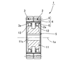
図1Aは本発明の実施の形態に係るデュアルタイプの波動歯車装置(以下、単に「波動歯車装置」と呼ぶ。)を示す端面図であり、図1Bは図1Aの1B−1B線で切断した部分を示す縦断面図である。また、図2は図1Aの波動歯車装置の模式図である。波動歯車装置1は、例えば減速機として用いられ、円環状の剛性の第1内歯歯車2と、円環状の剛性の第2内歯歯車3と、半径方向に撓み可能な薄肉弾性体からなる円筒形状の可撓性の外歯歯車4と、楕円状輪郭の波動発生器5とを備えている。
FIG. 1A is an end view showing a dual type wave gear device (hereinafter simply referred to as “wave gear device”) according to an embodiment of the present invention, and FIG. 1B is cut along
第1、第2内歯歯車2、3は、中心軸線1aの方向に、所定の隙間を開けて、同軸に並列配置されている。本例では、第1内歯歯車2は回転しないように固定された静止側内歯歯車であり、その第1内歯2aの歯数はZc1である。第2内歯歯車3は回転自在の状態に支持された駆動側内歯歯車であり、その第2内歯3aの歯数はZc2である。第2内歯歯車3は波動歯車装置1の減速回転出力要素である。
The first and second
円筒形状の外歯歯車4は、第1、第2内歯歯車2、3の内側に同軸に配置されている。外歯歯車4は、半径方向に撓み可能な薄肉弾性体である円筒体6と、この円筒体6の円形外周面に形成した第1外歯7および第2外歯8と、これらの間に形成したカッター逃げ部として機能する隙間9(図3A、3B、3C参照)とを備えている。第1外歯7は、円筒体6の円形外周面において、中心軸線1aの方向における一方の側に形成され、第2外歯8は他方の側に形成されている。これら第1、第2外歯7、8は、中心軸線1aの方向が歯筋方向となるように形成されている。
The cylindrical
すなわち、第1外歯7は第1内歯2aに対峙する側に形成され、その歯数はZf1であり、第1内歯2aにかみ合い可能である。第2外歯8は第2内歯3aに対峙する側に形成され、その歯数はZf2であり、第2内歯3aにかみ合い可能である。これらの歯数Zf1、Zf2は異なる。
That is, the first
波動発生器5は、楕円状輪郭の剛性プラグ11と、この剛性プラグ11の楕円状外周面に装着した第1ウエーブベアリング12および第2ウエーブベアリング13とを備えている。第1、第2ウエーブベアリング12、13はボールベアリングから形成されている。
The
波動発生器5は外歯歯車4の円筒体6の内周面に嵌め込まれ、円筒体6を楕円状に撓めている。したがって、第1、第2外歯7、8も楕円状に撓められている。楕円状に撓められた外歯歯車4は、その楕円形状の長軸Lmaxの両端位置において、第1、第2内歯歯車2、3にかみ合っている。すなわち、第1外歯7が楕円形状の長軸Lmaxの両端位置において第1内歯2aにかみ合っており、第2外歯8が長軸Lmaxの両端位置において第2内歯3aにかみ合っている。
The
波動発生器5は波動歯車装置1の入力回転要素である。波動発生器5の剛性プラグ11は軸穴11cを備えており、ここに、入力回転軸10(図2参照)が同軸に連結固定される。例えば、モーター出力軸が連結固定される。波動発生器5が回転すると、外歯歯車4の第1外歯7と静止側の第1内歯2aのかみ合い位置、および、外歯歯車4の第2外歯8と駆動側の第2内歯3aのかみ合い位置が円周方向に移動する。
The
第1外歯7の歯数Zf1と第2外歯8の歯数Zf2とは異なり、本例では第2外歯8の歯数Zf2の方が多い。また、第1内歯2aの歯数Zc1は第1外歯7の歯数Zf1とは異なり、本例では、第1内歯2aの歯数Zc1の方が多い。第2内歯3aの歯数Zc2と第2外歯8の歯数Zf2とは異なり、本例では、第2内歯3aの歯数Zc2の方が少ない。
Unlike the number of teeth Zf1 of the first
本例では、外歯歯車4が楕円状に撓められて円周方向の2か所で内歯歯車2、3にかみ合う。したがって、第1外歯7の歯数Zf1と第2外歯8の歯数Zf2との差は、n0を正の整数とすると、2n0枚である。同様に、第1内歯2aの歯数Zc1と第1外歯7の歯数Zf1との差は、n1を正の整数とすると、2n1枚である。第2内歯3aの歯数Zc2と第2外歯8の歯数Zf2との差は、n2を正の整数とすると、2n2枚である。
Zf2=Zf1+2n0
Zc1=Zf1+2n1
Zc2=Zf2−2n2
In this example, the
Zf2 = Zf1 + 2n 0
Zc1 = Zf1 + 2n 1
Zc2 = Zf2-2n 2
具体例として、各歯数は次のように設定される(n0=2、n1=n2=1)。
Zc1=62
Zf1=60
Zc2=62
Zf2=64
As a specific example, the number of teeth is set as follows (n 0 = 2, n 1 = n 2 = 1).
Zc1 = 62
Zf1 = 60
Zc2 = 62
Zf2 = 64
第1内歯歯車2と第1外歯7の間の速比R1、第2内歯歯車3と第2外歯8の間の速比R2は、それぞれ次のようになる。
i1=1/R1=(Zf1−Zc1)/Zf1=(60−62)/60=−1/30
i2=1/R2=(Zf2−Zc2)/Zf2=(64−62)/64=1/32
したがって、R1=−30、R2=32が得られる。
The speed ratio R1 between the first
i1 = 1 / R1 = (Zf1-Zc1) / Zf1 = (60-62) / 60 = -1 / 30
i2 = 1 / R2 = (Zf2-Zc2) / Zf2 = (64-62) / 64 = 1/32
Therefore, R1 = −30 and R2 = 32 are obtained.
波動歯車装置1の速比Rは、速比R1、R2を用いて、次式で表される。よって、本発明によれば、大幅に小さな速比(低減速比)の波動歯車装置を実現できる。(なお、速比のマイナス符号は、出力回転の方向が入力回転の方向とは逆方向であることを示す。)
R=(R1・R2−R1)/(−R1+R2)
=(−30×32+30)/(30+32)
=−930/62
=−15
The speed ratio R of the
R = (R1 · R2-R1) / (− R1 + R2)
= (− 30 × 32 + 30) / (30 + 32)
=-930/62
= -15
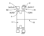
(隙間:カッター逃げ部)
図3A、図3Bおよび図3Cは、それぞれ、隙間9の形成例を示す説明図である。なお、図3B、図3Cにおいて、図3Aにおける各部に対応する部位には、図3Aにおける場合と同一の符号を付してある。第1、第2外歯7、8の間に形成されている隙間9は、第1、第2外歯7、8を歯切するために用いる歯切り用カッターのカッター逃げ部として機能する。
(Gap: Cutter clearance)
FIG. 3A, FIG. 3B and FIG. 3C are explanatory drawings each showing an example of formation of the gap 9. In FIGS. 3B and 3C, portions corresponding to the respective portions in FIG. 3A are denoted by the same reference numerals as in FIG. 3A. A gap 9 formed between the first and second
図3Aを参照して、第1、第2外歯7、8について説明する。本例の第1、第2内歯2a、3aの歯幅が実質的に同一である。したがって、円筒体6における歯筋方向の中央位置6aを中心として、対称な状態で同一歯幅の第1外歯7および第2外歯8が形成されている。第1内歯2a、第2内歯3aの歯幅が相互に異なる場合には、これに対応させて、第1外歯7、第2外歯8も異なる歯幅とされる。
The first and second
隙間9は、歯筋方向に所定の幅を有し、歯筋方向の中央部分において歯丈方向に最深となる最深部を有している。本例では、歯厚方向から見た場合に、歯筋方向の中央部分が歯筋方向に平行に延びる直線によって規定される最深部9aとなっている。最深部9aにおける歯筋方向の両端には、第1外歯7の歯筋方向の内側端面7aを規定する凹円弧曲線および第2外歯8の歯筋方向の内側端面8aを規定する凹円弧曲線が滑らかに繋がっている。最深部9aを凹曲面によって規定し、両側の内側端面7a、8aを傾斜直線によって規定することもできる。また、最深部9aを直線によって規定し、両側の内側端面7a、8aを傾斜直線によって規定することもできる。
The gap 9 has a predetermined width in the tooth trace direction, and has a deepest portion that is deepest in the tooth height direction at the center portion in the tooth trace direction. In this example, when viewed from the tooth thickness direction, the central portion in the tooth trace direction is the
本例の隙間9の歯筋方向の幅は、最深部9aから歯丈方向に向けて漸増している。その歯筋方向における最大幅L1は、第1外歯7の歯先円の歯筋方向の内側端7bから、第2外歯8の歯先円の歯筋方向の内側端8bまでの歯筋方向の距離である。
The width of the gap 9 in this example in the tooth trace direction gradually increases from the
ここで、第1外歯7の歯筋方向の外端7cから第2外歯8の歯筋方向の外端8cまでの幅をL、隙間9の歯筋方向における最大幅をL1とすると、
0.1L < L1 < 0.35L
に設定されている。
Here, when the width from the
0.1 L <
It is set to.
また、隙間9の最深部9aの深さは次のように設定されている。第1外歯7の歯丈をh1、第2外歯8の歯丈をh2、第1外歯7の歯先面7dから最深部9aまでの歯丈方向の深さをt1、第2外歯8の歯先面8dから最深部9aまでの歯丈方向の深さをt2とする。また、深さt1、t2は、次の条件1、条件2、および条件3のうちのいずれか一つを満足するように設定されている。図3Aは条件1を満たす場合の説明図であり、図3Bは条件2を満たす場合の説明図であり、図3Cは条件3を満たす場合の説明図である。
Further, the depth of the
(条件1)
0.9h1 < t1 < 1.3h1
0.3h2 < t2 < 0.9h2
(条件2)
0.3h1 < t1 < 0.9h1
0.9h2 < t2 < 1.3h2
(条件3)
0.3h1 < t1 < 0.9h1
( Condition 1 )
0.9h1 <t1 <1.3h1
0.3h2 <t2 <0.9h2
( Condition 2 )
0.3h1 <t1 <0.9h1
0.9h2 <t2 <1.3h2
( Condition 3 )
0.3h1 <t1 <0.9h1
デュアルタイプの波動歯車装置1の外歯歯車4においては、第1、第2外歯7、8の歯切りを行うために用いる歯切り用カッターも異なる。したがって、外歯歯車4の歯筋方向の中央部分、すなわち、第1外歯7と第2外歯8の間に、カッター逃げ部として機能する隙間9が形成されている。
In the
このように隙間9を形成することで、第1、第2外歯7、8の歯筋方向の歯面荷重分布を均一化でき、第1、第2内歯2a、3aに対する第1、第2外歯7、8の歯筋方向の各位置で歯当りも良好な状態に維持できる。特に、本例によれば、第1、第2外歯7、8において、それらの歯筋方向の内側端面の側の部分の剛性を相対的に上げることができる。これにより、負荷が加わった際の第1、第2外歯7、8のねじれを低減でき、第1、第2外歯7、8のそれぞれの内歯に対する片当たりが軽減される。この結果、歯のかみ合い部分において歯筋方向に応力が適切に分散され、外歯歯車4の耐摩耗性および疲労強度を大幅に高めることができる。したがって、速比が30以下の波動歯車装置を容易に実現できると共に、耐摩耗性および疲労強度が高く、負荷容量の高い波動歯車装置を実現できる。
By forming the gap 9 in this way, the tooth surface load distribution in the tooth trace direction of the first and second
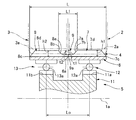
(ベアリングボール中心間距離)
次に、図3Aを参照して、第1、第2ウエーブベアリング12、13のベアリングボール中心間距離について説明する。
(Distance between bearing ball centers)
Next, with reference to FIG. 3A, the bearing ball center distance of the first and
波動発生器5の剛性プラグ11は、その中心軸線の方向の一方の側に、一定幅の楕円形輪郭の第1外周面11aが形成され、他方の側に、一定幅の楕円状輪郭の第2外周面11bが形成されている。第1外周面11aと第2外周面11bとは、同一形状で同一位相の楕円形状の外周面である。
The
第1外周面11aには、楕円状に撓められた状態で第1ウエーブベアリング12が装着されており、第2外周面11bには、楕円状に撓められた状態で第2ウエーブベアリング13が装着されている。第1、第2ウエーブベアリング12、13は同一サイズのベアリングである。
The first wave bearing 12 is attached to the first outer
第1ウエーブベアリング12および第2ウエーブベアリング13のベアリングボール中心12a、13aは、外歯歯車4の歯幅方向の中央位置6aから、歯幅方向に等距離の位置にある。また、ベアリングボール中心間距離は、隙間9の最大幅L1の増加に伴って増加するように設定される。さらに、ベアリングボール中心間距離をLoとすると、当該ボール中心間距離Loは次式で示す範囲内の値となるように設定されている。
0.35L < Lo < 0.7L
The bearing ball centers 12a and 13a of the first wave bearing 12 and the second wave bearing 13 are equidistantly spaced in the tooth width direction from the
0.35L <Lo <0.7L
本例では、歯数の異なる第1、第2外歯7、8の支持剛性を高め、各外歯7、8の歯筋方向の各位置において内歯2a、3aに対する歯当りを改善できるように、2列のウエーブベアリング12、13のボール中心間距離Loを広げてある。すなわち、上記のように、第1、第2外歯7、8の間に形成されるカッター逃げ部として機能する隙間9の歯筋方向の最大幅L1の増加に伴って、ボール中心間距離Loを広げる(増加させる)ようにしている。また、ボール中心間距離Loの増減の範囲を外歯歯車4の幅Lに対して0.35倍から0.7倍までの範囲としてある。
In this example, the support rigidity of the first and second
形成される隙間9の幅に応じて、第1、第2外歯7、8のそれぞれに対して、歯筋方向における適切な位置にボール中心が位置するように、第1、第2ウエーブベアリング12、13を配置できる。これにより、第1、第2外歯7、8のそれぞれの歯幅方向の各位置において、第1、第2外歯7、8を第1、第2ウエーブベアリング12、13によって確実に支持できる(波動発生器5の支持剛性を高めることができる。)。
According to the width of the gap 9 to be formed, the first and second wave bearings are arranged so that the center of the ball is positioned at an appropriate position in the tooth trace direction with respect to each of the first and second
この結果、第1、第2外歯7、8の歯幅方向の各位置における歯当りを改善でき、これらの歯底疲労強度を高めることができる。また、波動発生器5の各ウエーブベアリング12、13におけるベアリングボール荷重分布を平均化でき、その最大荷重を低減できるので、波動発生器5の寿命を改善できる。
As a result, the tooth contact at each position in the tooth width direction of the first and second
(その他の実施の形態)
なお、上記の例では、第1内歯歯車2を静止側内歯歯車、第2内歯歯車3を駆動側内歯歯車としている。逆に、第1内歯歯車2を駆動側内歯歯車、第2内歯歯車3を静止側内歯歯車とすることもできる。
(Other embodiments)
In the above example, the first
また、外歯歯車4は、波動発生器5によって、楕円状以外の非円形形状、例えば、スリーローブ状等の非円形形状に撓めることができる。非円形に撓めた外歯歯車と内歯歯車のかみ合い箇所の数をh(h:2以上の正の整数)とすると、両歯車の歯数差は、h・p(p:正の整数)に設定すればよい。
The
1 波動歯車装置
1a 中心軸線
2 第1内歯歯車
2a 第1内歯
3 第2内歯歯車
3a 第2内歯
4 外歯歯車
5 波動発生器
6 円筒体
6a 中央位置
7 第1外歯
7a 内側端面
7b 内側端
7c 外端
7d 歯先面
8 第2外歯
8a 内側端面
8b 内側端
8c 外端
8d 歯先面
9 隙間
9a 最深部
10 入力回転軸
11 剛性プラグ
11a 第1外周面
11b 第2外周面
11c 軸穴
12 第1ウエーブベアリング
12a ベアリングボール中心
13 第2ウエーブベアリング
13a ベアリングボール中心
Lo ベアリングボール中心間距離
L 幅
L1 最大幅
h1、h2 歯丈
t1、t2 深さ
DESCRIPTION OF
Claims (9)
前記第1内歯歯車に同軸に並列配置され、第2内歯が形成されている剛性の第2内歯歯車と、
前記第1、第2内歯歯車の内側に同軸に配置され、半径方向に撓み可能な円筒体の外周面に、前記第1内歯にかみ合い可能な第1外歯および前記第2内歯にかみ合い可能で前記第1外歯とは歯数が異なる第2外歯が形成されている可撓性の外歯歯車と、
前記外歯歯車を半径方向に撓めて、前記第1外歯を前記第1内歯に部分的にかみ合わせ、前記第2外歯を前記第2内歯に部分的にかみ合わせる波動発生器と、
を有しており、
前記第1外歯の歯筋方向の内側端面と前記第2外歯の歯筋方向の内側端面との間には、歯筋方向に所定幅を有し、歯筋方向の中央部分において歯丈方向に最深となる最深部を有する隙間が形成されており、
前記第1外歯の歯筋方向の外端から前記第2外歯の歯筋方向の外端までの歯筋方向の幅をL、前記隙間の歯筋方向における最大幅をL1とすると、
0.1L < L1 < 0.35L
に設定されており、
前記第1外歯の歯丈をh1、前記第2外歯の歯丈をh2、前記第1外歯の歯先面から前記最深部までの歯丈方向の深さをt1、前記第2外歯の歯先面から前記最深部までの歯丈方向の深さをt2とすると、
前記深さt1、t2は、3つの条件1〜3のうちのいずれか一つの条件を満足し、
前記条件1は、
0.9h1 < t1 < 1.3h1、および、
0.3h2 < t2 < 0.9h2であり、
前記条件2は、
0.3h1 < t1 < 0.9h1、および、
0.9h2 < t2 < 1.3h2であり、
前記条件3は、
0.3h1 < t1 < 0.9h1、および
0.3h2 < t2 < 0.9h2である
デュアルタイプの波動歯車装置。 A rigid first internal gear on which first internal teeth are formed;
A rigid second internal gear arranged coaxially in parallel with the first internal gear and forming a second internal tooth;
The first and second internal teeth are coaxially arranged inside the first and second internal gears, and can be engaged with the first internal teeth on the outer peripheral surface of the cylindrical body that can be bent in the radial direction. A flexible external gear having second external teeth that are meshable and have a different number of teeth from the first external teeth;
A wave generator that flexes the external gear in the radial direction, partially meshes the first external teeth with the first internal teeth, and partially meshes the second external teeth with the second internal teeth; ,
Have
Between the inner end face of the first external teeth in the direction of the teeth and the inner end face of the second teeth in the direction of the teeth, there is a predetermined width in the direction of the teeth, and A gap having a deepest part that is deepest in the direction is formed,
Let L be the width in the direction of the teeth from the outer end of the first external teeth in the direction of the teeth to the outer end of the second external teeth in the direction of the teeth, let L1 be the maximum width in the direction of the teeth in the gap,
0.1 L <L 1 <0.35 L
Is set to
The first external teeth have a height h1; the second external teeth have a height h2; and the depth in the direction of the depth from the tip of the first external teeth to the deepest portion t1; the second exterior Assuming that the depth in the height direction from the tip of the tooth to the deepest portion is t2 .
The depths t1 and t2 satisfy any one of three conditions 1 to 3,
Condition 1 is
0.9h1 <t1 <1.3h1 , and
0.3h2 <t2 <0.9h2 ,
Condition 2 is
0.3h1 <t1 <0.9h1 , and
0.9h2 <t2 <1.3h2 ,
Condition 3 is
0.3h1 <t1 <0.9h1, and is 0.3h2 <t2 <0.9h2
Dual type wave gear device.
前記第1、第2ウエーブベアリングのそれぞれのボール中心は、歯筋方向において、前記隙間における歯筋方向の中心から等しい距離に位置し、
前記第1、第2ウエーブベアリングのボール中心間距離をLoとすると、
前記ボール中心間距離Loは、前記隙間の最大幅L1の増加に伴って増加し、かつ、
0.35L < Lo < 0.7L
に設定されている請求項1に記載のデュアルタイプの波動歯車装置。 The wave generator comprises a first wave bearing comprising a ball bearing supporting the first external tooth, and a second wave bearing comprising a ball bearing supporting the second external tooth,
The respective ball centers of the first and second wave bearings are located in the tooth trace direction at an equal distance from the center of the tooth trace direction in the gap,
Assuming that the distance between the ball centers of the first and second wave bearings is Lo,
The ball center distance Lo increases as the maximum width L1 of the gap increases, and
0.35L <Lo <0.7L
The dual type wave gear device according to claim 1, wherein the dual type wave gear device is set.
前記第2外歯の歯数は前記第2内歯の歯数とは異なる、
請求項1に記載のデュアルタイプの波動歯車装置。 The number of teeth of the first external teeth is different from the number of teeth of the first internal teeth,
The number of teeth of the second external teeth is different from the number of teeth of the second internal teeth.
The dual-type wave gear device according to claim 1.
前記第1内歯の歯数と前記第2内歯の歯数は同一である、
請求項1に記載のデュアルタイプの波動歯車装置。 The number of teeth of the first external teeth is less than the number of teeth of the first internal teeth,
The number of teeth of the first internal teeth and the number of teeth of the second internal teeth are the same.
The dual-type wave gear device according to claim 1.
前記第1内歯歯車および前記第2内歯歯車のうち、一方は回転しないように固定された静止側内歯歯車であり、他方は減速回転出力要素である駆動側内歯歯車である、
請求項1に記載のデュアルタイプの波動歯車装置。 The wave generator is a rotational input element;
One of the first internal gear and the second internal gear is a stationary-side internal gear fixed so as not to rotate, and the other is a drive-side internal gear that is a reduction rotation output element.
The dual-type wave gear device according to claim 1.
前記第1外歯の歯数と前記第2外歯の歯数の差は、nを整数とすると、2n枚である、請求項1に記載のデュアルタイプの波動歯車装置。 The wave generator bends the external gear in an elliptical shape, engages the first external teeth at two places in the circumferential direction with respect to the first internal teeth, and the second external teeth. Engaging at two places in the circumferential direction with respect to the second internal tooth,
The dual type wave gear device according to claim 1, wherein the difference between the number of first external teeth and the number of second external teeth is 2 n, where n is an integer.
前記第1、第2ウエーブベアリングのそれぞれのボール中心は、歯筋方向において、前記隙間における歯筋方向の中心から等しい距離に位置し、
前記第1、第2ウエーブベアリングのボール中心間距離をLoとすると、
前記ボール中心間距離Loは、前記隙間の最大幅L1の増加に伴って増加し、かつ、
0.35L < Lo < 0.7L
に設定されており、
前記第1外歯の歯数は前記第1内歯の歯数とは異なり、前記第2外歯の歯数は前記第2内歯の歯数とは異なり、
前記波動発生器は回転入力要素であり、前記第1内歯歯車および前記第2内歯歯車のうち、一方は回転しないように固定された静止側内歯歯車であり、他方は減速回転出力要素である駆動側内歯歯車である、
請求項1に記載のデュアルタイプの波動歯車装置。 The wave generator comprises a first wave bearing comprising a ball bearing supporting the first external tooth, and a second wave bearing comprising a ball bearing supporting the second external tooth,
The respective ball centers of the first and second wave bearings are located in the tooth trace direction at an equal distance from the center of the tooth trace direction in the gap,
Assuming that the distance between the ball centers of the first and second wave bearings is Lo,
The ball center distance Lo increases as the maximum width L1 of the gap increases, and
0.35L <Lo <0.7L
Is set to
The number of teeth of the first external teeth is different from the number of teeth of the first internal teeth, the number of teeth of the second external teeth is different from the number of teeth of the second internal teeth,
The wave generator is a rotation input element, and one of the first internal gear and the second internal gear is a stationary internal gear fixed so as not to rotate, and the other is a reduced rotation output element. It is a drive side internal gear that is
The dual-type wave gear device according to claim 1.
請求項7に記載のデュアルタイプの波動歯車装置。 The wave generator bends the external gear in an elliptical shape, engages the first external teeth at two places in the circumferential direction with respect to the first internal teeth, and the second external teeth. When the number of teeth of the first external teeth and the number of teeth of the second external teeth is n, n is an integer, and 2n is engaged with the second internal teeth at two places in the circumferential direction. Is a sheet,
The dual-type wave gear device according to claim 7.
前記第1、第2ウエーブベアリングのそれぞれのボール中心は、歯筋方向において、前記隙間における歯筋方向の中心から等しい距離に位置し、
前記第1、第2ウエーブベアリングのボール中心間距離をLoとすると、
前記ボール中心間距離Loは、前記隙間の最大幅L1の増加に伴って増加し、かつ、
0.35L < Lo < 0.7L
に設定されており、
前記第1外歯の歯数は前記第1内歯の歯数よりも少なく、前記第1内歯の歯数と前記第2内歯の歯数は同一であり、
前記波動発生器は回転入力要素であり、前記第1内歯歯車および前記第2内歯歯車のうち、一方は回転しないように固定された静止側内歯歯車であり、他方は減速回転出力要素である駆動側内歯歯車であり、
前記波動発生器は、前記外歯歯車を楕円状に撓めて、前記第1外歯を前記第1内歯に対して円周方向の2か所の部位でかみ合わせ、前記第2外歯を前記第2内歯に対して円周方向の2か所の部位でかみ合わせており、前記第1外歯の歯数と前記第2外歯の歯数の差は2枚である、
請求項1に記載のデュアルタイプの波動歯車装置。 The wave generator comprises a first wave bearing comprising a ball bearing supporting the first external tooth, and a second wave bearing comprising a ball bearing supporting the second external tooth,
The respective ball centers of the first and second wave bearings are located in the tooth trace direction at an equal distance from the center of the tooth trace direction in the gap,
Assuming that the distance between the ball centers of the first and second wave bearings is Lo,
The ball center distance Lo increases as the maximum width L1 of the gap increases, and
0.35L <Lo <0.7L
Is set to
The number of first external teeth is smaller than the number of first internal teeth, and the number of first internal teeth is the same as the number of second internal teeth.
The wave generator is a rotation input element, and one of the first internal gear and the second internal gear is a stationary internal gear fixed so as not to rotate, and the other is a reduced rotation output element. Drive side internal gear that is
The wave generator bends the external gear in an elliptical shape, engages the first external teeth at two places in the circumferential direction with respect to the first internal teeth, and the second external teeth. The second internal teeth are engaged at two places in the circumferential direction, and the difference between the number of teeth of the first external teeth and the number of teeth of the second external teeth is two.
The dual-type wave gear device according to claim 1.
Priority Applications (10)
| Application Number | Priority Date | Filing Date | Title |
|---|---|---|---|
| JP2017191871A JP6552571B2 (en) | 2017-09-29 | 2017-09-29 | Dual type wave gear device |
| EP18863424.0A EP3690280B1 (en) | 2017-09-29 | 2018-08-30 | Dual-type wave gear device |
| MX2019006403A MX2019006403A (en) | 2017-09-29 | 2018-08-30 | Dual-type wave gear device. |
| CN201880006728.1A CN111108307B (en) | 2017-09-29 | 2018-08-30 | Duplex wave gear device |
| PCT/JP2018/032257 WO2019065070A1 (en) | 2017-09-29 | 2018-08-30 | Dual-type wave gear device |
| RU2019112402A RU2714353C1 (en) | 2017-09-29 | 2018-08-30 | Double-shaft transmission |
| KR1020197014389A KR102209016B1 (en) | 2017-09-29 | 2018-08-30 | Dual type wave gear device |
| BR112019009060A BR112019009060A2 (en) | 2017-09-29 | 2018-08-30 | double type harmonic gear |
| US16/346,941 US11280370B2 (en) | 2017-09-29 | 2018-08-30 | Dual-type strain wave gearing |
| TW107131809A TWI698600B (en) | 2017-09-29 | 2018-09-11 | Dual-type strain wave gearing |
Applications Claiming Priority (1)
| Application Number | Priority Date | Filing Date | Title |
|---|---|---|---|
| JP2017191871A JP6552571B2 (en) | 2017-09-29 | 2017-09-29 | Dual type wave gear device |
Publications (3)
| Publication Number | Publication Date |
|---|---|
| JP2019065958A JP2019065958A (en) | 2019-04-25 |
| JP2019065958A5 JP2019065958A5 (en) | 2019-06-27 |
| JP6552571B2 true JP6552571B2 (en) | 2019-07-31 |
Family
ID=65903093
Family Applications (1)
| Application Number | Title | Priority Date | Filing Date |
|---|---|---|---|
| JP2017191871A Active JP6552571B2 (en) | 2017-09-29 | 2017-09-29 | Dual type wave gear device |
Country Status (10)
| Country | Link |
|---|---|
| US (1) | US11280370B2 (en) |
| EP (1) | EP3690280B1 (en) |
| JP (1) | JP6552571B2 (en) |
| KR (1) | KR102209016B1 (en) |
| CN (1) | CN111108307B (en) |
| BR (1) | BR112019009060A2 (en) |
| MX (1) | MX2019006403A (en) |
| RU (1) | RU2714353C1 (en) |
| TW (1) | TWI698600B (en) |
| WO (1) | WO2019065070A1 (en) |
Families Citing this family (4)
| Publication number | Priority date | Publication date | Assignee | Title |
|---|---|---|---|---|
| JP2020034128A (en) * | 2018-08-31 | 2020-03-05 | セイコーエプソン株式会社 | Gear device, gear device unit and robot |
| JP6793867B1 (en) * | 2020-06-29 | 2020-12-02 | 株式会社ハーモニック・ドライブ・システムズ | Strain wave gearing unit |
| CN114370487B (en) * | 2022-01-24 | 2023-12-12 | 王瑞松 | Harmonic speed reducer and transmission device |
| DE102022124529B3 (en) | 2022-09-23 | 2023-12-21 | Harmonic Drive Se | Flat gear |
Family Cites Families (13)
| Publication number | Priority date | Publication date | Assignee | Title |
|---|---|---|---|---|
| DE3738521C1 (en) * | 1987-11-13 | 1988-12-01 | Delta Getriebe Gmbh | Planetary gear |
| KR100988215B1 (en) * | 2008-06-24 | 2010-10-18 | 한국과학기술연구원 | Harmonic drive using profile shifted gear |
| CN105358871A (en) * | 2013-07-01 | 2016-02-24 | 谐波传动系统有限公司 | Strain wave gear device |
| US9360098B2 (en) * | 2013-10-29 | 2016-06-07 | Roopnarine | Strain wave drive with improved performance |
| JP6218693B2 (en) * | 2014-07-23 | 2017-10-25 | 株式会社ハーモニック・ドライブ・システムズ | Dual type wave gear device |
| JP6370624B2 (en) * | 2014-07-23 | 2018-08-08 | 株式会社ハーモニック・ドライブ・システムズ | Dual type wave gear device |
| JP6218690B2 (en) * | 2014-07-23 | 2017-10-25 | 株式会社ハーモニック・ドライブ・システムズ | Dual type wave gear device |
| JP6218691B2 (en) * | 2014-07-23 | 2017-10-25 | 株式会社ハーモニック・ドライブ・システムズ | Dual type wave gear device |
| JP6218692B2 (en) * | 2014-07-23 | 2017-10-25 | 株式会社ハーモニック・ドライブ・システムズ | Dual type wave gear device |
| JP6324832B2 (en) * | 2014-07-23 | 2018-05-16 | 株式会社ハーモニック・ドライブ・システムズ | Dual type wave gear device |
| RU2659313C1 (en) * | 2014-08-06 | 2018-06-29 | Хармоник Драйв Системс Инк. | Coplanar harmonic gear drive |
| KR102102748B1 (en) | 2016-02-11 | 2020-04-22 | 삼성전자주식회사 | Electronic apparatus, external apparatus and method for controlling a power supply of external apparatus |
| LU93010B1 (en) * | 2016-03-30 | 2017-10-23 | Ovalo Gmbh | Tension shaft gear |
-
2017
- 2017-09-29 JP JP2017191871A patent/JP6552571B2/en active Active
-
2018
- 2018-08-30 WO PCT/JP2018/032257 patent/WO2019065070A1/en unknown
- 2018-08-30 MX MX2019006403A patent/MX2019006403A/en unknown
- 2018-08-30 US US16/346,941 patent/US11280370B2/en active Active
- 2018-08-30 RU RU2019112402A patent/RU2714353C1/en active
- 2018-08-30 KR KR1020197014389A patent/KR102209016B1/en active IP Right Grant
- 2018-08-30 CN CN201880006728.1A patent/CN111108307B/en active Active
- 2018-08-30 BR BR112019009060A patent/BR112019009060A2/en not_active Application Discontinuation
- 2018-08-30 EP EP18863424.0A patent/EP3690280B1/en active Active
- 2018-09-11 TW TW107131809A patent/TWI698600B/en active
Also Published As
| Publication number | Publication date |
|---|---|
| JP2019065958A (en) | 2019-04-25 |
| TWI698600B (en) | 2020-07-11 |
| EP3690280A4 (en) | 2021-04-14 |
| WO2019065070A1 (en) | 2019-04-04 |
| RU2714353C1 (en) | 2020-02-14 |
| KR102209016B1 (en) | 2021-01-27 |
| CN111108307A (en) | 2020-05-05 |
| BR112019009060A2 (en) | 2019-07-16 |
| EP3690280A1 (en) | 2020-08-05 |
| MX2019006403A (en) | 2019-08-29 |
| CN111108307B (en) | 2023-02-28 |
| US20200056653A1 (en) | 2020-02-20 |
| US11280370B2 (en) | 2022-03-22 |
| TW201920854A (en) | 2019-06-01 |
| KR20190069526A (en) | 2019-06-19 |
| EP3690280B1 (en) | 2022-07-27 |
Similar Documents
| Publication | Publication Date | Title |
|---|---|---|
| JP6552571B2 (en) | Dual type wave gear device | |
| JP6218691B2 (en) | Dual type wave gear device | |
| JP6218692B2 (en) | Dual type wave gear device | |
| JP6218690B2 (en) | Dual type wave gear device | |
| JP6351724B2 (en) | Flat wave gear device | |
| JP6324832B2 (en) | Dual type wave gear device | |
| JP6370624B2 (en) | Dual type wave gear device | |
| JP6218693B2 (en) | Dual type wave gear device |
Legal Events
| Date | Code | Title | Description |
|---|---|---|---|
| A521 | Request for written amendment filed |
Free format text: JAPANESE INTERMEDIATE CODE: A523 Effective date: 20190523 |
|
| A621 | Written request for application examination |
Free format text: JAPANESE INTERMEDIATE CODE: A621 Effective date: 20190523 |
|
| A871 | Explanation of circumstances concerning accelerated examination |
Free format text: JAPANESE INTERMEDIATE CODE: A871 Effective date: 20190523 |
|
| A975 | Report on accelerated examination |
Free format text: JAPANESE INTERMEDIATE CODE: A971005 Effective date: 20190611 |
|
| TRDD | Decision of grant or rejection written | ||
| A01 | Written decision to grant a patent or to grant a registration (utility model) |
Free format text: JAPANESE INTERMEDIATE CODE: A01 Effective date: 20190702 |
|
| A61 | First payment of annual fees (during grant procedure) |
Free format text: JAPANESE INTERMEDIATE CODE: A61 Effective date: 20190702 |
|
| R150 | Certificate of patent or registration of utility model |
Ref document number: 6552571 Country of ref document: JP Free format text: JAPANESE INTERMEDIATE CODE: R150 |
|
| R250 | Receipt of annual fees |
Free format text: JAPANESE INTERMEDIATE CODE: R250 |
|
| R250 | Receipt of annual fees |
Free format text: JAPANESE INTERMEDIATE CODE: R250 |