JP6370624B2 - Dual type wave gear device - Google Patents
Dual type wave gear device Download PDFInfo
- Publication number
- JP6370624B2 JP6370624B2 JP2014149372A JP2014149372A JP6370624B2 JP 6370624 B2 JP6370624 B2 JP 6370624B2 JP 2014149372 A JP2014149372 A JP 2014149372A JP 2014149372 A JP2014149372 A JP 2014149372A JP 6370624 B2 JP6370624 B2 JP 6370624B2
- Authority
- JP
- Japan
- Prior art keywords
- teeth
- external
- internal
- gear
- wave
- Prior art date
- Legal status (The legal status is an assumption and is not a legal conclusion. Google has not performed a legal analysis and makes no representation as to the accuracy of the status listed.)
- Active
Links
Images


Classifications
-
- F—MECHANICAL ENGINEERING; LIGHTING; HEATING; WEAPONS; BLASTING
- F16—ENGINEERING ELEMENTS AND UNITS; GENERAL MEASURES FOR PRODUCING AND MAINTAINING EFFECTIVE FUNCTIONING OF MACHINES OR INSTALLATIONS; THERMAL INSULATION IN GENERAL
- F16H—GEARING
- F16H49/00—Other gearings
- F16H49/001—Wave gearings, e.g. harmonic drive transmissions
-
- F—MECHANICAL ENGINEERING; LIGHTING; HEATING; WEAPONS; BLASTING
- F16—ENGINEERING ELEMENTS AND UNITS; GENERAL MEASURES FOR PRODUCING AND MAINTAINING EFFECTIVE FUNCTIONING OF MACHINES OR INSTALLATIONS; THERMAL INSULATION IN GENERAL
- F16H—GEARING
- F16H1/00—Toothed gearings for conveying rotary motion
- F16H1/28—Toothed gearings for conveying rotary motion with gears having orbital motion
- F16H1/32—Toothed gearings for conveying rotary motion with gears having orbital motion in which the central axis of the gearing lies inside the periphery of an orbital gear
-
- F—MECHANICAL ENGINEERING; LIGHTING; HEATING; WEAPONS; BLASTING
- F16—ENGINEERING ELEMENTS AND UNITS; GENERAL MEASURES FOR PRODUCING AND MAINTAINING EFFECTIVE FUNCTIONING OF MACHINES OR INSTALLATIONS; THERMAL INSULATION IN GENERAL
- F16H—GEARING
- F16H49/00—Other gearings
- F16H49/001—Wave gearings, e.g. harmonic drive transmissions
- F16H2049/003—Features of the flexsplines therefor
Description
本発明は、一対の内歯歯車、半径方向に撓み可能な円筒状の外歯歯車、および波動発生器を備えた波動歯車装置に関する。 The present invention relates to a pair of internal gears, a cylindrical external gear that can be bent in the radial direction, and a wave gear device that includes a wave generator.
円筒状の外歯歯車を備えた波動歯車装置は、一般に、回転しないように固定される静止側内歯歯車と、回転入力要素である波動発生器と、減速回転出力要素である駆動側内歯歯車と、静止側内歯歯車および駆動側内歯歯車にかみ合い可能で半径方向に撓み可能な円筒状の外歯歯車とを備えている。典型的な波動歯車装置では、外歯歯車は楕円状に撓められて静止側および駆動側の内歯歯車に対して楕円形状の長軸両端の位置でかみ合っている。 A wave gear device having a cylindrical external gear generally includes a stationary-side internal gear that is fixed so as not to rotate, a wave generator that is a rotation input element, and a drive-side internal tooth that is a reduction rotation output element. A gear and a cylindrical external gear that can mesh with the stationary-side internal gear and the driving-side internal gear and bend in the radial direction are provided. In a typical wave gear device, the external gear is bent in an elliptical shape and meshes with the stationary-side and driving-side internal gears at positions on both ends of the elliptical long axis.
特許文献1には、静止側内歯歯車の歯数が外歯歯車より2枚多く、駆動側内歯歯車の歯数が外歯歯車と同一の一般的な波動歯車装置が記載されている。外歯歯車の外歯は、その歯筋方向の中央部分で二分され、一方の外歯部分が静止側内歯歯車にかみ合い可能であり、他方の外歯部分が駆動側内歯歯車にかみ合い可能である。波動発生器が回転すると、外歯歯車が、静止側内歯歯車との歯数差に応じた速比で減速回転する。外歯歯車と一体回転する駆動側内歯歯車から、外歯歯車の減速回転が出力される。
特許文献2には、静止側内歯歯車の歯数が外歯歯車よりも2枚多く、駆動側内歯歯車の歯数が外歯歯車よりも2枚少ない波動歯車装置が記載されている。この波動歯車装置では、波動発生器が回転すると、外歯歯車が、静止側内歯歯車との歯数差に応じた速比で減速回転する。外歯歯車の回転は、当該外歯歯車と駆動側内歯歯車との間の歯数差に応じた速比で増速されて、駆動側内歯歯車から出力される。駆動側内歯歯車から出力される回転は、波動発生器への入力回転に対して、速比50よりも小さな速比で減速された減速回転になる。
一方、特許文献2、3には、2列のボールベアリングを備えた波動発生器を有する波動歯車装置が記載されている。この形式の波動発生器は、楕円状輪郭の外周面を備えた剛性プラグと、この外周面に装着した2列のボールベアリングとから構成される。楕円状に撓められている各ボールベアリングの外輪の外周面の長軸両端の部分によって、可撓性外歯歯車が半径方向の外方に押されて、第1、第2剛性内歯歯車に対するかみ合いが保持される。
On the other hand,
ここで、外歯歯車として、半径方向に撓み可能な円筒体の外周面に、一方の内歯歯車にかみ合い可能な第1外歯と、他方の内歯歯車にかみ合い可能で第1外歯とは歯数の異なる第2外歯とが形成されたものを用いることが考えられる。このようにすれば、特許文献2に記載されている波動歯車装置と同様に、速比が50未満の波動歯車装置を実現可能である。また、特許文献2に記載の波動歯車装置に比べて、50未満の速比を備えた波動歯車
装置を、より高い自由度で設計可能になる。
Here, as the external gear, on the outer peripheral surface of the cylindrical body that can be bent in the radial direction, a first external tooth that can mesh with one internal gear, and a first external tooth that can mesh with the other internal gear It is conceivable to use those formed with second external teeth having different numbers of teeth. In this way, a wave gear device having a speed ratio of less than 50 can be realized as in the wave gear device described in
本明細書においては、撓み可能な円筒体の外周面に、歯数が異なる第1、第2外歯が形成されている外歯歯車を備えた波動歯車装置を、「デュアルタイプの波動歯車装置」と呼ぶものとする。 In the present specification, a wave gear device including an external gear having first and second external teeth having different numbers of teeth formed on the outer peripheral surface of a bendable cylindrical body is referred to as “dual type wave gear device”. ".
デュアルタイプの波動歯車装置においては、外歯歯車の第1外歯および第2外歯が共通の円筒体の外周面に形成されており、それらの歯底リム部は相互に繋がっている。円筒体が波動発生器によって楕円状に撓められると、歯数の異なる第1、第2外歯は、それぞれ別の内歯歯車にかみ合う。 In the dual-type wave gear device, the first external teeth and the second external teeth of the external gear are formed on the outer peripheral surface of a common cylindrical body, and the root rim portions thereof are connected to each other. When the cylindrical body is bent elliptically by the wave generator, the first and second external teeth having different numbers of teeth mesh with different internal gears.
ここで、各外歯の撓み量の設定は、それらの外歯のかみ合い状態、耐摩耗性、および歯底疲労強度に大きく影響を与える。また、各外歯の撓み状態は、第1、第2外歯を支持する波動発生器の各ウエーブベアリングのボール荷重分布に大きく影響を与え、これらのウエーブベアリングの寿命にも影響を与える。 Here, the setting of the deflection amount of each external tooth greatly affects the meshing state, wear resistance, and root fatigue strength of the external teeth. In addition, the bending state of each external tooth greatly affects the ball load distribution of each wave bearing of the wave generator that supports the first and second external teeth, and also affects the life of these wave bearings.
第1、第2外歯が独立した歯車の場合には、各歯車を、別個の波動発生器によって、各歯車に適した撓み量となるように楕円状に撓めることができる。これにより、第1、第2外歯をそれぞれ適切なかみ合い状態で対応する内歯にかみ合わせることができる。 In the case where the first and second external teeth are independent gears, each gear can be bent elliptically by a separate wave generator so as to have a bending amount suitable for each gear. Thereby, a 1st, 2nd external tooth can be meshed | engaged with a corresponding internal tooth in an appropriate meshing state, respectively.
しかしながら、デュアルタイプの波動歯車装置の場合には、共通の円筒体の外周面に第1、第2外歯が形成されているので、第1、第2外歯をそれらの歯数に応じて異なる撓み量で独立して撓めることができない。また、一方の外歯に適した撓み量で円筒体を撓めると、他方の外歯のかみ合い状態を適切な状態に維持できないことがある。さらに、第1、第2外歯のそれぞれの撓み状態が他方の撓み状態に影響を及ぼすので、双方の撓み状態の相互作用を考慮しないと、各外歯を適切なかみ合い状態となるように撓めることができない。 However, in the case of the dual type wave gear device, the first and second external teeth are formed on the outer peripheral surface of the common cylindrical body, and therefore the first and second external teeth are set according to the number of teeth. It cannot be bent independently with different bending amounts. Further, if the cylindrical body is bent with a bending amount suitable for one external tooth, the meshing state of the other external tooth may not be maintained in an appropriate state. Further, since the bending state of each of the first and second external teeth affects the other bending state, the bending of each external tooth so as to be in an appropriate meshing state without considering the interaction of both of the bending states. I can't stop.
本発明の課題は、このような点に鑑みて、歯数の異なる第1、第2外歯を適切に撓めて各内歯歯車との間で良好なかみ合い状態を形成可能なデュアルタイプの波動歯車装置を提供することにある。 In view of such a point, the problem of the present invention is a dual type capable of forming a good meshing state with each internal gear by appropriately bending the first and second external teeth having different numbers of teeth. The object is to provide a wave gear device.
また、本発明の課題は、歯数の異なる第1、第2外歯を適切に撓めることにより、これらを支持する波動発生器のウエーブベアリングのベアリングボール荷重分布の均一化を図ったデュアルタイプの波動歯車装置を提供することにある。 Another object of the present invention is to provide a dual bearing ball load distribution of a wave bearing of a wave generator that supports the first and second external teeth having different numbers of teeth by appropriately bending them. The object is to provide a wave gear device of the type.
上記の課題を解決するために、本発明のデュアルタイプの波動歯車装置は、
第1内歯が形成されている剛性の第1内歯歯車と、
前記第1内歯歯車に同軸に並列配置され、第2内歯が形成されている剛性の第2内歯歯車と、
前記第1、第2内歯歯車の内側に同軸に配置され、半径方向に撓み可能な円筒体の外周面に、前記第1内歯にかみ合い可能な第1外歯および前記第2内歯にかみ合い可能で前記第1外歯とは歯数が異なる第2外歯が形成されている可撓性の外歯歯車と、
前記外歯歯車を楕円状に撓めて、前記第1外歯を前記第1内歯に部分的にかみ合わせ、前記第2外歯を前記第2内歯に部分的にかみ合わせる波動発生器と、
を有しており、
前記第1外歯のモジュールをm1、前記第2外歯のモジュールをm2とし、
n1、n2を正の整数として、前記第1外歯と前記第1内歯の歯数差を2n1、前記第2外歯と前記第2内歯の歯数差を2n2と表し、
楕円状に撓められる前記第1外歯の長軸位置における半径方向撓み量の理論値d1および前記第2外歯の半径方向撓み量の理論値d2を、それぞれ、
d1=m1n1
d2=m2n2
と表すものとすると、
前記波動発生器によって撓められる前記第1外歯の半径方向撓み量をd1a、第2外歯の半径方向撓み量をd2a、ωを1よりも大きな値の係数とすると、これらの半径方向撓み量d1a、d2aは、
d1a=ωd1
d2a=ωd2
であることを特徴としている。
In order to solve the above problems, the dual-type wave gear device of the present invention includes:
A rigid first internal gear on which first internal teeth are formed;
A rigid second internal gear arranged coaxially in parallel with the first internal gear and forming a second internal tooth;
The first and second internal teeth are coaxially arranged inside the first and second internal gears, and can be engaged with the first internal teeth on the outer peripheral surface of the cylindrical body that can be bent in the radial direction. A flexible external gear having second external teeth that are meshable and have a different number of teeth from the first external teeth;
A wave generator that bends the external gear into an ellipse, partially meshes the first external teeth with the first internal teeth, and partially meshes the second external teeth with the second internal teeth; ,
Have
The module of the first external tooth is m 1 , the module of the second external tooth is m 2 ,
n 1 and n 2 are positive integers, the difference in the number of teeth between the first external teeth and the first internal teeth is represented by 2n 1 , and the difference in the number of teeth between the second external teeth and the second internal teeth is represented by 2n 2. ,
The theoretical value d 2 in the radial deflection amount in the radial direction deflection amount of theory d 1 and the second external teeth in the long axis position of the first external teeth flexed into an elliptical shape, respectively,
d 1 = m 1 n 1
d 2 = m 2 n 2
If
When the amount of radial deflection of the first external teeth deflected by the wave generator is d 1a , the amount of radial deflection of the second external teeth is d 2a , and ω is a coefficient having a value larger than 1, these radii The direction deflection amounts d 1a and d 2a are:
d 1a = ωd 1
d 2a = ωd 2
It is characterized by being.
すなわち、第1、第2外歯の半径方向撓み量d1、d2の双方が、それらの理論値d1、d2よりも大きくなるように設定される。具体的には、このような撓み量で第1、第2外歯が撓められるように、波動発生器の輪郭形状が設定される。 That is, both the radial deflection amounts d 1 and d 2 of the first and second external teeth are set to be larger than their theoretical values d 1 and d 2 . Specifically, the contour shape of the wave generator is set so that the first and second external teeth are bent with such a bending amount.
ここで、係数ωの値は次の範囲内とすることが望ましい。
1.25 ≦ ω ≦ 3
Here, the value of the coefficient ω is preferably within the following range.
1.25 ≦ ω ≦ 3
外歯歯車を楕円状に撓める前の真円の状態において、その円筒体(歯底リム)の厚みの中央を通る円をリム中立円とする。このリム中立円は、外歯歯車を楕円状に撓めることによって楕円状に変形する。これを楕円状リム中立曲線と呼ぶものとする。外歯歯車の半径方向撓み量は、楕円状リム中立曲線における長軸の半径とリム中立円の半径との差であり、外歯歯車のモジュールをm、2n(n:正の整数)を内歯歯車との歯数差、ωを撓み係数として、ωmnと表される。ω=1の場合の半径方向撓み量mnは、外歯歯車のピッチ円直径を、剛性内歯車を固定した場合の減速比で除した値であり、これが半径方向撓み量の理論値(標準撓み量)である。 In the state of a perfect circle before the external gear is bent into an ellipse, a circle passing through the center of the thickness of the cylindrical body (bottom rim) is defined as a rim neutral circle. The rim neutral circle is deformed into an ellipse by bending the external gear into an ellipse. This is called an elliptical rim neutral curve. The amount of bending in the radial direction of the external gear is the difference between the radius of the major axis and the radius of the rim neutral circle in the elliptical rim neutral curve, and the external gear module is m, 2n (n: positive integer). The difference in the number of teeth from the toothed gear, ω, is expressed as ωmn, with the deflection coefficient as the deflection coefficient. The radial deflection amount mn when ω = 1 is a value obtained by dividing the pitch circle diameter of the external gear by the reduction ratio when the rigid internal gear is fixed, and this is a theoretical value (standard deflection) of the radial deflection amount. Amount).
同一の円筒体の外周面に形成されている歯数の異なる第1、第2外歯の場合には、双方のピッチ円直径がほぼ同一である。よって、半径方向撓み量の理論値mnは歯数の多い方が小さくなる。 In the case of the first and second external teeth having different numbers of teeth formed on the outer peripheral surface of the same cylindrical body, both pitch circle diameters are substantially the same. Therefore, the theoretical value mn of the amount of bending in the radial direction becomes smaller as the number of teeth increases.
本発明では、歯数の異なる第1、第2外歯の半径方向撓み量を双方共に、上記のように、理論値よりも大きな値(ω>1)に設定してある。このように第1、第2外歯の撓み量を理論値よりも大きな値に設定すると、双方の外歯を共に良好なかみ合い状態で内歯のそれぞれにかみ合わせることができ、第1、第2外歯の耐摩耗性および歯底疲労強度を高めることが可能である。特に、上記ようにωの値を設定することで、第1、第2外歯の良好なかみ合い状態を形成でき、それらの耐摩耗性および歯底疲労強度を高めることができる。 In the present invention, the radial deflection amounts of the first and second external teeth having different numbers of teeth are both set to a value (ω> 1) larger than the theoretical value as described above. Thus, when the amount of bending of the first and second external teeth is set to a value larger than the theoretical value, both the external teeth can be engaged with each of the internal teeth in a good meshing state. 2 It is possible to increase the wear resistance and root fatigue strength of the external teeth. In particular, by setting the value of ω as described above, a good meshing state of the first and second external teeth can be formed, and their wear resistance and root fatigue strength can be increased.
また、波動発生器が、第1、第2外歯をそれぞれ支持している2列のウエーブベアリングを備えている場合には、各ウエーブベアリングのベアリングボール荷重分布の均一化を図ることができる。これにより、ウエーブベアリングの寿命を向上させることができる。 Further, when the wave generator includes two rows of wave bearings that respectively support the first and second external teeth, the bearing ball load distribution of each wave bearing can be made uniform. Thereby, the lifetime of a wave bearing can be improved.
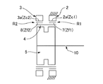
次に、本発明のデュアルタイプの波動歯車装置において、第1内歯の歯数をZc1、第2内歯の歯数をZc2、第1外歯の歯数をZf1、第2外歯の歯数をZf2とすると、第1内歯歯車と第1外歯を備えた外歯歯車との間の速比R1、第2内歯歯車と第2外歯を備えた外歯歯車との間の速比R2、および、波動歯車装置の速比Rは、それぞれ次のように表される。
R1=1/{(Zf1−Zc1)/Zf1}
R2=1/{(Zf2−Zc2)/Zf2}
R=(R1・R2−R1)/(−R1+R2)
Next, in the dual type wave gear device of the present invention, the number of teeth of the first internal teeth is Zc1, the number of teeth of the second internal teeth is Zc2, the number of teeth of the first external teeth is Zf1, and the number of teeth of the second external teeth When the number is Zf2, the speed ratio R1 between the first internal gear and the external gear provided with the first external teeth, and between the second internal gear and the external gear provided with the second external teeth The speed ratio R2 and the speed ratio R of the wave gear device are respectively expressed as follows.
R1 = 1 / {(Zf1-Zc1) / Zf1}
R2 = 1 / {(Zf2-Zc2) / Zf2}
R = (R1 · R2-R1) / (− R1 + R2)
したがって、50未満、例えば、30よりも大幅に低い速比を得ることが可能である。また、従来とは異なり、外歯歯車の外歯として、歯数、モジュールの異なる第1外歯および第2外歯が形成されている。よって、速比設定のための設計の自由度が高く、低い速比の波動歯車装置を従来に比べて、容易に実現できる。 It is thus possible to obtain a speed ratio of less than 50, for example significantly lower than 30. Further, unlike the prior art, first external teeth and second external teeth having different number of teeth and modules are formed as external teeth of the external gear. Therefore, the degree of freedom in design for setting the speed ratio is high, and a wave gear device with a low speed ratio can be easily realized as compared with the conventional one.
本発明のデュアルタイプの波動歯車装置では、一般に、第1外歯の歯数Zf1は第1内歯の歯数Zc1とは異なり、第2外歯の歯数Zf2は第2内歯の歯数Zc2とは異なる。例えば、第1外歯の歯数Zf1を第1内歯の歯数Zc1よりも少なくし、第1内歯の歯数Zc1と第2内歯の歯数Zc2を同一とすることができる。 In the dual-type wave gear device of the present invention, generally, the number of teeth Zf1 of the first external teeth is different from the number of teeth Zc1 of the first internal teeth, and the number of teeth Zf2 of the second external teeth is the number of teeth of the second internal teeth. Different from Zc2. For example, the number of teeth Zf1 of the first external teeth can be made smaller than the number of teeth Zc1 of the first internal teeth, and the number of teeth Zc1 of the first internal teeth and the number of teeth Zc2 of the second internal teeth can be made the same.
また、波動発生器が回転入力要素とされ、第1内歯歯車および第2内歯歯車のうち、一方が回転しないように固定された静止側内歯歯車とされ、他方が減速回転出力要素である駆動側内歯歯車とされる。 The wave generator is a rotation input element, one of the first internal gear and the second internal gear is a stationary internal gear fixed so as not to rotate, and the other is a reduced rotation output element. A certain drive-side internal gear is used.
以下に、図面を参照して、本発明を適用したデュアルタイプの波動歯車装置の実施の形態を説明する。 Hereinafter, an embodiment of a dual-type wave gear device to which the present invention is applied will be described with reference to the drawings.
図1(a)は本発明の実施の形態に係るデュアルタイプの波動歯車装置(以下、単に「波動歯車装置」と呼ぶ。)を示す端面図であり、図1(b)は図1(a)のb−b線で切断した部分を示す縦断面図である。また、図2は図1の波動歯車装置の模式図である。波動歯車装置1は、例えば減速機として用いられ、円環状の剛性の第1内歯歯車2と、円環状の剛性の第2内歯歯車3と、半径方向に撓み可能な薄肉弾性体からなる円筒形状の可撓性の外歯歯車4と、楕円状輪郭の波動発生器5とを備えている。
FIG. 1A is an end view showing a dual-type wave gear device (hereinafter simply referred to as “wave gear device”) according to an embodiment of the present invention, and FIG. It is a longitudinal cross-sectional view which shows the part cut | disconnected by the bb line | wire of (). FIG. 2 is a schematic diagram of the wave gear device of FIG. The
第1、第2内歯歯車2、3は、中心軸線1aの方向に、所定の隙間を開けて、同軸に並列配置されている。本例では、第1内歯歯車2は回転しないように固定された静止側内歯歯車であり、その第1内歯2aの歯数はZc1である。第2内歯歯車3は回転自在の状態に支持された駆動側内歯歯車であり、その第2内歯3aの歯数はZc2である。第2内歯歯車3は波動歯車装置1の減速回転出力要素である。
The first and second
円筒形状の外歯歯車4は、第1、第2内歯歯車2、3の内側に同軸に配置されている。外歯歯車4は、半径方向に撓み可能な薄肉弾性体である円筒体6と、この円筒体6の円形外周面に形成した第1外歯7および第2外歯8と、これらの間に形成したカッター逃げ部として機能する隙間9(図3参照)とを備えている。第1外歯7は、円筒体6の円形外周面において、中心軸線1aの方向における一方の側に形成され、第2外歯8は他方の第2内歯3aの側に形成されている。これら第1、第2外歯7、8は、中心軸線1aの方向が歯筋方向となるように形成されている。
The cylindrical
すなわち、第1外歯7は第1内歯2aに対峙する側に形成され、その歯数はZf1であ
り、第1内歯2aにかみ合い可能である。第2外歯8は第2内歯3aに対峙する側に形成され、その歯数はZf2であり、第2内歯3aにかみ合い可能である。これらの歯数Zf1、Zf2は異なる。
That is, the 1st
波動発生器5は、楕円状輪郭の剛性プラグ11と、この剛性プラグ11の楕円状外周面に装着した第1ウエーブベアリング12および第2ウエーブベアリング13とを備えている。第1、第2ウエーブベアリング12、13はボールベアリングから形成されている。
The
波動発生器5は外歯歯車4の円筒体6の内周面に嵌め込まれ、円筒体6を楕円状に撓めている。したがって、第1、第2外歯7、8も楕円状に撓められている。楕円状に撓められた外歯歯車4は、その楕円形状の長軸Lmaxの両端位置において、第1、第2内歯歯車2、3にかみ合っている。すなわち、第1外歯7が楕円形状の長軸の両端位置において第1内歯2aにかみ合っており、第2外歯8が長軸の両端位置において第2内歯3aにかみ合っている。
The
波動発生器5は波動歯車装置1の入力回転要素である。波動発生器5の剛性プラグ11は軸穴11cを備えており、ここに、入力回転軸10(図2参照)が同軸に連結固定される。例えば、モーター出力軸が連結固定される。波動発生器5が回転すると、外歯歯車4の第1外歯7と静止側の第1内歯2aのかみ合い位置、および、外歯歯車4の第2外歯8と駆動側の第2内歯3aのかみ合い位置が円周方向に移動する。
The
第1外歯7の歯数Zf1と第2外歯8の歯数Zf2とは異なり、本例では第2外歯Zf2の歯数の方が多い。また、第1内歯2aの歯数Zc1は第1外歯7の歯数Zf1とは異なり、本例では、第1内歯2aの歯数Zc1の方が多い。第2内歯3aの歯数Zc2と第2外歯8の歯数Zf2とは異なり、本例では、第2内歯3aの歯数Zc2の方が少ない。
Unlike the number of teeth Zf1 of the first
本例では、外歯歯車4が楕円状に撓められて円周方向の2か所で内歯歯車2、3にかみ合う。したがって、第1外歯7の歯数Zf1と第2外歯8の歯数Zf2との差は、n0を正の整数とすると、2n0枚である。同様に、第1内歯2aの歯数Zc1と第1外歯7の歯数Zf1との差は、n1を正の整数とすると、2n1枚である。第2内歯3aの歯数Zc2と第2外歯8の歯数Zf2との差は、n2を正の整数とすると、2n2枚である。
Zf1=Zf2+2n0
Zc1=Zf1+2n1
Zc2=Zf2−2n2
In this example, the
Zf1 = Zf2 + 2n 0
Zc1 = Zf1 + 2n 1
Zc2 = Zf2-2n 2
具体例として、各歯数は次のように設定される(n0=n1=n2=1)。
Zc1=62
Zf1=60
Zc2=62
Zf2=64
As a specific example, the number of teeth is set as follows (n 0 = n 1 = n 2 = 1).
Zc1 = 62
Zf1 = 60
Zc2 = 62
Zf2 = 64
第1内歯歯車2と第1外歯7の間の速比R1、第2内歯歯車3と第2外歯8の間の速比R2は、それぞれ次のようになる。
i1=1/R1=(Zf1−Zc1)/Zf1=(60−62)/60=−1/30
i2=1/R2=(Zf2−Zc2)/Zf2=(64−62)/64=1/32
したがって、R1=−30、R2=32が得られる。
The speed ratio R1 between the first
i1 = 1 / R1 = (Zf1-Zc1) / Zf1 = (60-62) / 60 = -1 / 30
i2 = 1 / R2 = (Zf2-Zc2) / Zf2 = (64-62) / 64 = 1/32
Therefore, R1 = −30 and R2 = 32 are obtained.
波動歯車装置1の速比Rは、速比R1、R2を用いて、次式で表される。よって、本発明によれば、大幅に小さな速比(低減速比)の波動歯車装置を実現できる。(なお、速比のマイナス符号は、出力回転の方向が入力回転の方向とは逆方向であることを示す。)
R=(R1・R2−R1)/(−R1+R2)
=(−30×32+30)/(30+32)
=−930/62
=−15
The speed ratio R of the
R = (R1 · R2-R1) / (− R1 + R2)
= (− 30 × 32 + 30) / (30 + 32)
= -930 / 62
= -15
(隙間:カッター逃げ部)
図3は波動歯車装置1の部分拡大断面図であり、外歯歯車4および波動発生器5の第1、第2ウエーブベアリング12、13を示す。第1、第2外歯7、8の間に形成されている隙間9は、第1、第2外歯7、8を歯切するために用いる歯切り用カッターのカッター逃げ部として機能する。
(Gap: Cutter clearance)
FIG. 3 is a partial enlarged cross-sectional view of the
まず、第1、第2外歯7、8について説明する。本例の第1、第2内歯2a、3aの歯幅が実質的に同一である。したがって、円筒体6における歯筋方向の中央位置6aを中心として、対称な状態で同一歯幅の第1外歯7および第2外歯8が形成されている。第1内歯2a、第2内歯3aの歯幅が相互に異なる場合には、これに対応させて、第1外歯7、第2外歯8も異なる歯幅とされる。
First, the first and second
隙間9は、歯筋方向に所定の幅を有し、歯筋方向の中央部分において歯丈方向に最深となる最深部を有している。本例では、歯厚方向から見た場合に、歯筋方向の中央部分が歯筋方向に平行に延びる直線によって規定される最深部9aとなっている。最深部9aにおける歯筋方向の両端には、第1外歯7の歯筋方向の内側端面7aを規定する凹円弧曲線および第2外歯8の歯筋方向の内側端面8aを規定する凹円弧曲線が滑らかに繋がっている。最深部9aを凹曲面によって規定し、両側の内側端面7a、8aを傾斜直線によって規定することもできる。また、最深部9aを直線によって規定し、両側の内側端面7a、8aを傾斜直線によって規定することもできる。
The gap 9 has a predetermined width in the tooth trace direction, and has a deepest portion that is deepest in the tooth height direction at the center portion in the tooth trace direction. In this example, when viewed from the tooth thickness direction, the central portion in the tooth trace direction is the
本例の隙間9の歯筋方向の幅は、最深部9aから歯丈方向に向けて漸増している。その歯筋方向における最大幅L1は、第1外歯7の歯先円の歯筋方向の内側端7bから、第2外歯8の歯先円の歯筋方向の内側端8bまでの歯筋方向の距離である。
The width of the gap 9 in this example in the tooth trace direction gradually increases from the
ここで、第1外歯7の歯筋方向の外端7cから第2外歯8の歯筋方向の外端8cまでの幅をL、隙間9の歯筋方向における最大幅をL1とすると、
0.1L < L1 < 0.3L
に設定されている。
Here, when the width from the
0.1L <L1 <0.3L
Is set to
また、隙間9の最深部9aの深さは次のように設定されている。第1外歯7の歯丈をh1、第2外歯8の歯丈をh2、第1外歯7の歯先面7dから最深部9aまでの歯丈方向の深さをt1、第2外歯8の歯先面8dから最深部9aまでの歯丈方向の深さをt2とすると、
0.9h1 < t1 < 1.3h1
0.9h2 < t2 < 1.3h2
に設定されている。
Further, the depth of the
0.9h1 <t1 <1.3h1
0.9h2 <t2 <1.3h2
Is set to
デュアルタイプの波動歯車装置1の外歯歯車4においては、第1、第2外歯7、8の歯切りを行うために用いる歯切り用カッターも異なる。したがって、外歯歯車4の歯筋方向の中央部分、すなわち、第1外歯7と第2外歯8の間に、カッター逃げ部として機能する隙間9が形成されている。
In the
この隙間9をどのように形成するのかによって、歯筋方向における第1内歯2aに対する第1外歯7の歯当り、および歯面荷重分布が大きく影響を受ける。同様に、歯筋方向に
おける第2内歯3aに対する第2外歯8の歯当り、および歯面荷重分布が大きく影響を受ける。
The contact of the first
この点に着目して、上記のように、隙間9の最大幅L1を外歯歯車4の幅Lの0.1倍から0.3倍までの範囲内に設定し、その最大深さt1、t2を、第1、第2外歯7、8の歯丈h1、h2の0.9倍から1.3倍までの範囲内に設定している。このように隙間9を形成することで、第1、第2外歯7、8の歯筋方向の歯面荷重分布を均一化でき、第1、第2内歯2a、3aに対する第1、第2外歯7、8の歯筋方向の各位置で歯当りも良好な状態に維持できることが確認された。
Focusing on this point, as described above, the maximum width L1 of the gap 9 is set within the range of 0.1 to 0.3 times the width L of the
したがって、速比が30以下の波動歯車装置を容易に実現できると共に、外歯歯車の歯底疲労強度が高く、負荷容量の大きな波動歯車装置を実現できる。 Therefore, a wave gear device having a speed ratio of 30 or less can be easily realized, and a wave gear device having a high tooth bottom fatigue strength and a large load capacity can be realized.
(ベアリングボール中心間距離)
次に、図3を参照して第1、第2ウエーブベアリング12、13のベアリングボール中心間距離について説明する。
(Bearing ball center distance)
Next, the distance between the bearing ball centers of the first and
波動発生器5の剛性プラグ11は、その中心軸線の方向の一方の側に、一定幅の楕円形輪郭の第1外周面11aが形成され、他方の側に、一定幅の楕円状輪郭の第2外周面11bが形成されている。第1外周面11aと第2外周面11bとは、同一形状で同一位相の楕円形状の外周面である。
The
第1外周面11aには、楕円状に撓められた状態で第1ウエーブベアリング12が装着されており、第2外周面11bには、楕円状に撓められた状態で第2ウエーブベアリング13が装着されている。第1、第2ウエーブベアリング12、13は同一サイズのベアリングである。
A first wave bearing 12 is mounted on the first outer
第1ウエーブベアリング12および第2ウエーブベアリング13のベアリングボール中心12a、13aは、外歯歯車4の歯幅方向の中央位置6aから、歯幅方向に等距離の位置にある。また、ベアリングボール中心間距離は、隙間9の最大幅L1の増加に伴って増加するように設定される。さらに、ベアリングボール中心間距離をLoとすると、当該ボール中心間距離Loは次式で示す範囲内の値となるように設定されている。
0.35L < Lo < 0.7L
The bearing ball centers 12a and 13a of the first wave bearing 12 and the second wave bearing 13 are located equidistant from the
0.35L <Lo <0.7L
従来においては、外歯歯車の支持面積を広くするために、2列のボールベアリングを備えた波動発生器が使用されている。ボール中心間距離については何ら考慮されておらず、2列のボールベアリングは外歯歯車の歯幅方向の中央部分に寄せて配置されている。 Conventionally, a wave generator having two rows of ball bearings is used to increase the support area of the external gear. No consideration is given to the distance between the centers of the balls, and the two rows of ball bearings are arranged close to the central portion of the external gear in the tooth width direction.
本例では、歯数の異なる第1、第2外歯7、8の支持剛性を高め、各外歯7、8の歯筋方向の各位置において内歯2a、3aに対する歯当りを改善できるように、2列のウエーブベアリング12、13のボール中心間距離Loを広げてある。すなわち、上記のように、第1、第2外歯7、8の間に形成されるカッター逃げ部として機能する隙間9の歯筋方向の最大幅L1の増加に伴って、ボール中心間距離Loを広げる(増加させる)ようにしている。また、ボール中心間距離Loの増減の範囲を外歯歯車4の幅Lに対して0.35倍から0.7倍までの範囲としてある。
In this example, the support rigidity of the first and second
これにより、形成される隙間9の幅に応じて、第1、第2外歯7、8のそれぞれに対して、歯筋方向における適切な位置にボール中心が位置するように、第1、第2ウエーブベアリング12、13を配置できる。これにより、第1、第2外歯7、8のそれぞれの歯幅方向の各位置において、第1、第2外歯7、8を第1、第2ウエーブベアリング12、1
3によって確実に支持できる(波動発生器5の支持剛性を高めることができる。)。
Thereby, according to the width | variety of the clearance gap 9 formed, with respect to each of the 1st, 2nd
3 can be reliably supported (the support rigidity of the
この結果、第1、第2外歯7、8の歯幅方向の各位置における歯当りを改善でき、これらの歯底疲労強度を高めることができる。また、波動発生器5の各ウエーブベアリング12、13におけるベアリングボール荷重分布を平均化でき、その最大荷重を低減できるので、波動発生器5の寿命を改善できる。
As a result, the tooth contact at each position in the tooth width direction of the first and second
(外歯歯車の撓み量)
本例の外歯歯車4の第1、第2外歯7、8は、上記構成の2列のウエーブベアリング12、13を備えた波動発生器5によって、異なる撓み量で楕円形状に撓められる。第1外歯7のモジュールをm1、第2外歯8のモジュールをm2とする。先に述べたように、第1外歯7と第1内歯2aの歯数差は2n1であり、第2外歯8と第2内歯3aの歯数差は2n2である。
(Bending amount of external gear)
The first and second
楕円状に撓められる第1外歯7の長軸位置Lmaxにおける半径方向撓み量の理論値d1および前記第2外歯8の半径方向撓み量の理論値d2を、それぞれ、
d1=m1n1
d2=m2n2
と表すことができる。
The theoretical value d 1 of the radial direction deflection amount at the major axis position Lmax of the first
d 1 = m 1 n 1
d 2 = m 2 n 2
It can be expressed as.
本例では、波動発生器5によって撓められる第1外歯7の半径方向撓み量d1aをその理論値d1よりも大きな値にしてある。同様に、第2外歯8の半径方向撓み量d2も、その理論値d2よりも大きな値にしてある。特に、本例では、半径方向撓み量d1a、d2aを、次の範囲内に設定している。
d1a=ωd1
d2a=ωd2
1.25 ≦ ω ≦ 3
In this example, the radial direction deflection d 1a of the first
d 1a = ωd 1
d 2a = ωd 2
1.25 ≦ ω ≦ 3
図4は外歯歯車4の撓み状態を誇張して示す説明図である。この図4を参照して説明すると、外歯歯車4を楕円状に撓める前の真円の状態において、その円筒体(歯底リム)6の厚みの中央を通る円をリム中立円Cとする。このリム中立円Cは、外歯歯車4を楕円状に撓めることによって楕円状に変形する。これを楕円状リム中立曲線と呼ぶものとする。外歯歯車4の半径方向撓み量は、楕円状リム中立曲線における長軸Lmaxの半径とリム中立円Cの半径との差である。
FIG. 4 is an explanatory diagram exaggeratingly illustrating the bending state of the
本例では、第1外歯7の側の半径方向撓み量が第2外歯8の側の半径方向撓み量よりも多い。したがって、図4において誇張して示すように、長軸Lmaxを含む断面においては、外歯歯車4は、その歯筋方向に沿って、第2外歯8の外端8cから第1外歯7の外端7cに向けて、外端8cからの距離に略比例して撓み量が増加する。上記の半径方向撓み量d1aおよびd2aは、それぞれ第1、第2外歯7、8の平均撓み量である。それらの歯筋方向の中央位置における撓み量(楕円状リム中立曲線C1、C2とリム中立円Cとの差)に略等しい。
In this example, the amount of radial deflection on the first
歯数の異なる第1、第2外歯7、8を、上記のように理論値よりも大きな値に設定することにより、双方の外歯7、8を共に良好なかみ合い状態で、各内歯歯車にかみ合わせることができ、第1、第2外歯7、8の耐摩耗性および歯底疲労強度が改善されることが確認された。また、第1、第2外歯7、8のそれぞれを支持している2列のウエーブベアリング12、13のベアリングボール荷重分布を均一化でき、ウエーブベアリング12、13の寿命を向上できることが確認された。
By setting the first and second
(その他の実施の形態)
なお、上記の例では、第1内歯歯車2を静止側内歯歯車、第2内歯歯車3を駆動側内歯歯車としている。逆に、第1内歯歯車2を駆動側内歯歯車、第2内歯歯車3を静止側内歯歯車とすることもできる。
(Other embodiments)
In the above example, the first
1 波動歯車装置、
1a 中心軸線、
2 第1内歯歯車、
2a 第1内歯、
3 第2内歯歯車、
3a 第2内歯、
4 外歯歯車、
5 波動発生器、
6 円筒体、
6a 中央位置、
7 第1外歯、
7a 内側端面、
7b 内側端、
7c 外端、
7d 歯先面、
8 第2外歯、
8a 内側端面、
8b 内側端、
8c 外端、
8d 歯先面、
9 隙間、
9a 最深部、
10 入力回転軸、
11 剛性プラグ、
11a 第1外周面、
11b 第2外周面、
11c 軸穴、
12 第1ウエーブベアリング、
12a ベアリングボール中心、
13 第2ウエーブベアリング、
13a ベアリングボール中心、
Lo ベアリングボール中心間距離、
L 幅、
L1 最大幅、
h1 歯丈、
h2 歯丈、
t1 深さ、
t2 深さ、
C リム中立円
C1、C2 楕円状リム中立曲線、
Lmax 長軸
1 wave gear device,
1a central axis,
2 1st internal gear,
2a first internal teeth,
3 Second internal gear,
3a second internal teeth,
4 external gears,
5 Wave generator,
6 cylinder,
6a center position,
7 first external teeth,
7a inner end face,
7b inner edge,
7c outer end,
7d tooth tip surface,
8 Second external teeth,
8a inner end face,
8b inner edge,
8c outer end,
8d tooth tip surface,
9 Clearance,
9a deepest part,
10 input rotation axis,
11 Rigid plug,
11a 1st outer peripheral surface,
11b 2nd outer peripheral surface,
11c shaft hole,
12 First wave bearing,
12a Bearing ball center,
13 Second wave bearing,
13a bearing ball center,
Lo Bearing ball center distance,
L width,
L1 maximum width,
h1 tooth height,
h2 tooth height,
t1 depth,
t2 depth,
C rim neutral circle C1, C2 Elliptic rim neutral curve,
Lmax long axis
Claims (4)
前記第1内歯歯車に同軸に並列配置され、第2内歯が形成されている剛性の第2内歯歯車と、
前記第1、第2内歯歯車の内側に同軸に配置され、半径方向に撓み可能な円筒体の外周面に、前記第1内歯にかみ合い可能な第1外歯および前記第2内歯にかみ合い可能で前記第1外歯とは歯数が異なる第2外歯が形成されている可撓性の外歯歯車と、
前記外歯歯車を楕円状に撓めて、前記第1外歯を前記第1内歯に部分的にかみ合わせ、前記第2外歯を前記第2内歯に部分的にかみ合わせる波動発生器と、
を有しており、
前記波動発生器は、剛性のプラグと、前記プラグの外周面に形成した楕円状輪郭の外周面と、前記外周面に装着され、前記第1外歯を支持するボールベアリングからなる第1ウエーブベアリングと、前記外周面に装着され、前記第2外歯を支持するボールベアリングからなる第2ウエーブベアリングとを備えており、
前記第1外歯のモジュールをm1、前記第2外歯のモジュールをm2とし、
n1、n2を正の整数として、前記第1外歯と前記第1内歯の歯数差を2n1、前記第2外歯と前記第2内歯の歯数差を2n2と表し、
楕円状に撓められる前記第1外歯の長軸位置における半径方向撓み量の理論値d1および前記第2外歯の半径方向撓み量の理論値d2を、それぞれ、
d1=m1n1
d2=m2n2
と表すものとすると、
前記波動発生器によって撓められる前記第1外歯の半径方向撓み量をd1a、第2外歯の半径方向撓み量をd2a、ωを1よりも大きな値を有する係数であるとすると、
前記第1外歯の前記半径方向撓み量d 1a が前記第2外歯の前記半径方向撓み量d 2a よりも大きく、
前記長軸位置を含む断面においては、前記外歯歯車は、その歯筋方向に沿って、前記第2外歯の外端から第1外歯の外端に向けて、前記外端からの距離に応じて撓み量が増加しており、
前記半径方向撓み量d 1a およびd 2a は、それぞれ前記第1、第2外歯7、8の平均半径方向撓み量であり、
これらの半径方向撓み量d1a、d2aは、
d1a=ωd1
d2a=ωd2
であり、
前記係数ωは、
1.4 ≦ ω ≦ 3
であることを特徴とするデュアルタイプの波動歯車装置。 A rigid first internal gear on which first internal teeth are formed;
A rigid second internal gear arranged coaxially in parallel with the first internal gear and forming a second internal tooth;
The first and second internal teeth are coaxially arranged inside the first and second internal gears, and can be engaged with the first internal teeth on the outer peripheral surface of the cylindrical body that can be bent in the radial direction. A flexible external gear having second external teeth that are meshable and have a different number of teeth from the first external teeth;
A wave generator that bends the external gear into an ellipse, partially meshes the first external teeth with the first internal teeth, and partially meshes the second external teeth with the second internal teeth; ,
Have
The wave generator includes a rigid plug, an outer peripheral surface having an elliptical shape formed on an outer peripheral surface of the plug, and a first wave bearing comprising a ball bearing mounted on the outer peripheral surface and supporting the first external teeth. And a second wave bearing comprising a ball bearing mounted on the outer peripheral surface and supporting the second external teeth,
The module of the first external tooth is m 1 , the module of the second external tooth is m 2 ,
n 1 and n 2 are positive integers, the difference in the number of teeth between the first external teeth and the first internal teeth is represented by 2n 1 , and the difference in the number of teeth between the second external teeth and the second internal teeth is represented by 2n 2. ,
The theoretical value d 2 in the radial deflection amount in the radial direction deflection amount of theory d 1 and the second external teeth in the long axis position of the first external teeth flexed into an elliptical shape, respectively,
d 1 = m 1 n 1
d 2 = m 2 n 2
If
Assuming that the radial deflection amount of the first external teeth deflected by the wave generator is d 1a , the radial deflection amount of the second external teeth is d 2a , and ω is a coefficient having a value larger than 1.
The radial deflection amount d 1a of the first external teeth is larger than the radial deflection amount d 2a of the second external teeth ,
In the cross section including the major axis position, the external gear is a distance from the outer end toward the outer end of the first external tooth from the outer end of the second external tooth along the tooth trace direction. The amount of deflection increases according to
The radial deflection amounts d 1a and d 2a are average radial deflection amounts of the first and second external teeth 7 and 8, respectively.
These radial deflection amounts d 1a and d 2a are:
d 1a = ωd 1
d 2a = ωd 2
And
The coefficient ω is
1.4 ≦ ω ≦ 3
A dual-type wave gear device, characterized in that
前記第2外歯の歯数は前記第2内歯の歯数とは異なる、
請求項1に記載の波動歯車装置。 The number of teeth of the first external teeth is different from the number of teeth of the first internal teeth,
The number of teeth of the second external teeth is different from the number of teeth of the second internal teeth.
The wave gear device according to claim 1.
前記第1内歯の歯数と前記第2内歯の歯数は同一である、
請求項1または2に記載の波動歯車装置。 The number of teeth of the first external teeth is less than the number of teeth of the first internal teeth,
The number of teeth of the first internal teeth and the number of teeth of the second internal teeth are the same.
The wave gear device according to claim 1 or 2.
前記第1内歯歯車および前記第2内歯歯車のうち、一方は回転しないように固定された静止側内歯歯車であり、他方は減速回転出力要素である駆動側内歯歯車である、
請求項1ないし3のうちのいずれか一つの項に記載の波動歯車装置。 The wave generator is a rotational input element;
One of the first internal gear and the second internal gear is a stationary-side internal gear fixed so as not to rotate, and the other is a drive-side internal gear that is a reduction rotation output element.
The wave gear device according to any one of claims 1 to 3.
Priority Applications (10)
| Application Number | Priority Date | Filing Date | Title |
|---|---|---|---|
| JP2014149372A JP6370624B2 (en) | 2014-07-23 | 2014-07-23 | Dual type wave gear device |
| KR1020167035464A KR101918011B1 (en) | 2014-07-23 | 2015-07-03 | Dual-type wave gear device |
| PCT/JP2015/069244 WO2016013380A1 (en) | 2014-07-23 | 2015-07-03 | Dual-type wave gear device |
| CN201580038728.6A CN106536976B (en) | 2014-07-23 | 2015-07-03 | Amphistyly Wave gear device |
| RU2016148940A RU2658846C1 (en) | 2014-07-23 | 2015-07-03 | Dual harmonic gear drive |
| MX2017001006A MX2017001006A (en) | 2014-07-23 | 2015-07-03 | Dual-type wave gear device. |
| BR112017000370-8A BR112017000370B1 (en) | 2014-07-23 | 2015-07-03 | DUAL TYPE TENSION WAVE GEAR |
| EP15824221.4A EP3173659B1 (en) | 2014-07-23 | 2015-07-03 | Dual-type wave gear device |
| US15/327,866 US10309513B2 (en) | 2014-07-23 | 2015-07-03 | Dual-type strain wave gearing |
| TW104123405A TWI608185B (en) | 2014-07-23 | 2015-07-20 | Dual type strain wave gearing |
Applications Claiming Priority (1)
| Application Number | Priority Date | Filing Date | Title |
|---|---|---|---|
| JP2014149372A JP6370624B2 (en) | 2014-07-23 | 2014-07-23 | Dual type wave gear device |
Publications (3)
| Publication Number | Publication Date |
|---|---|
| JP2016023744A JP2016023744A (en) | 2016-02-08 |
| JP2016023744A5 JP2016023744A5 (en) | 2017-01-05 |
| JP6370624B2 true JP6370624B2 (en) | 2018-08-08 |
Family
ID=55162912
Family Applications (1)
| Application Number | Title | Priority Date | Filing Date |
|---|---|---|---|
| JP2014149372A Active JP6370624B2 (en) | 2014-07-23 | 2014-07-23 | Dual type wave gear device |
Country Status (10)
| Country | Link |
|---|---|
| US (1) | US10309513B2 (en) |
| EP (1) | EP3173659B1 (en) |
| JP (1) | JP6370624B2 (en) |
| KR (1) | KR101918011B1 (en) |
| CN (1) | CN106536976B (en) |
| BR (1) | BR112017000370B1 (en) |
| MX (1) | MX2017001006A (en) |
| RU (1) | RU2658846C1 (en) |
| TW (1) | TWI608185B (en) |
| WO (1) | WO2016013380A1 (en) |
Families Citing this family (5)
| Publication number | Priority date | Publication date | Assignee | Title |
|---|---|---|---|---|
| CN107387725A (en) * | 2017-08-10 | 2017-11-24 | 金明必 | Flexible gear and its component, decelerator and speed reducing ratio algorithm using the component |
| JP6912989B2 (en) * | 2017-09-27 | 2021-08-04 | 住友重機械工業株式会社 | Flexible meshing gear device |
| JP6552571B2 (en) * | 2017-09-29 | 2019-07-31 | 株式会社ハーモニック・ドライブ・システムズ | Dual type wave gear device |
| JP2019105311A (en) * | 2017-12-13 | 2019-06-27 | 本田技研工業株式会社 | Force distribution device |
| CN112145650B (en) * | 2020-09-28 | 2022-03-25 | 珠海格力电器股份有限公司 | Rigidity compensation device, harmonic speed reducer and robot |
Family Cites Families (20)
| Publication number | Priority date | Publication date | Assignee | Title |
|---|---|---|---|---|
| SU912980A1 (en) * | 1980-06-30 | 1982-03-15 | Московское Ордена Ленина И Ордена Трудового Красного Знамени Высшее Техническое Училище Им. Н.Э.Баумана | Doubled wave toothed gearing |
| JPS6491151A (en) | 1987-10-02 | 1989-04-10 | Ricoh Kk | Device for operating copying machine |
| JPH0451235Y2 (en) | 1987-12-10 | 1992-12-02 | ||
| JP2718540B2 (en) | 1989-04-17 | 1998-02-25 | 株式会社ハーモニック・ドライブ・システムズ | Wave gear device |
| UA78075C2 (en) * | 2005-02-07 | 2007-02-15 | Robert Vachahan Ambartsumiants | Method for determination of teeth module of involute cylindrical toothed wheels |
| JP2007303592A (en) * | 2006-05-12 | 2007-11-22 | Honda Motor Co Ltd | Harmonic drive |
| US8028603B2 (en) | 2007-12-04 | 2011-10-04 | Harmonic Drive Systems Inc. | Method for setting gear tooth profile in flat wave gear device on side where gears have same number of teeth |
| JP4877837B2 (en) * | 2007-12-04 | 2012-02-15 | 株式会社ハーモニック・ドライブ・システムズ | Tooth profile setting method for the same number of teeth side gear of flat type wave gear device |
| JP5064300B2 (en) * | 2008-05-28 | 2012-10-31 | 株式会社ハーモニック・ドライブ・システムズ | Wave gear type linear motion mechanism |
| KR100988215B1 (en) * | 2008-06-24 | 2010-10-18 | 한국과학기술연구원 | Harmonic drive using profile shifted gear |
| JP4948479B2 (en) * | 2008-06-26 | 2012-06-06 | 株式会社ハーモニック・ドライブ・システムズ | Compound wave gear reducer |
| JP5275150B2 (en) * | 2009-06-23 | 2013-08-28 | 株式会社ハーモニック・ドライブ・システムズ | Wave gear device |
| JP5337008B2 (en) * | 2009-11-30 | 2013-11-06 | 住友重機械工業株式会社 | Flexure meshing gear device and method of manufacturing the external gear |
| JP5256249B2 (en) * | 2010-06-18 | 2013-08-07 | 住友重機械工業株式会社 | Bending gear system |
| TWI412674B (en) * | 2010-11-17 | 2013-10-21 | Ind Tech Res Inst | Reducer structure and its wave gear drive |
| JP5840214B2 (en) * | 2011-09-16 | 2016-01-06 | 株式会社ハーモニック・ドライブ・システムズ | Wave gear device for generating vibration |
| JP5639992B2 (en) | 2011-12-08 | 2014-12-10 | 住友重機械工業株式会社 | Bending gear system |
| JP5833480B2 (en) * | 2012-03-21 | 2015-12-16 | 本田技研工業株式会社 | Wave gear device and walking assist device |
| US9360098B2 (en) * | 2013-10-29 | 2016-06-07 | Roopnarine | Strain wave drive with improved performance |
| JP6218692B2 (en) * | 2014-07-23 | 2017-10-25 | 株式会社ハーモニック・ドライブ・システムズ | Dual type wave gear device |
-
2014
- 2014-07-23 JP JP2014149372A patent/JP6370624B2/en active Active
-
2015
- 2015-07-03 RU RU2016148940A patent/RU2658846C1/en active
- 2015-07-03 MX MX2017001006A patent/MX2017001006A/en unknown
- 2015-07-03 CN CN201580038728.6A patent/CN106536976B/en active Active
- 2015-07-03 US US15/327,866 patent/US10309513B2/en active Active
- 2015-07-03 WO PCT/JP2015/069244 patent/WO2016013380A1/en active Application Filing
- 2015-07-03 EP EP15824221.4A patent/EP3173659B1/en active Active
- 2015-07-03 BR BR112017000370-8A patent/BR112017000370B1/en active IP Right Grant
- 2015-07-03 KR KR1020167035464A patent/KR101918011B1/en active IP Right Grant
- 2015-07-20 TW TW104123405A patent/TWI608185B/en active
Also Published As
| Publication number | Publication date |
|---|---|
| TWI608185B (en) | 2017-12-11 |
| EP3173659A4 (en) | 2018-07-11 |
| BR112017000370A2 (en) | 2018-03-13 |
| US10309513B2 (en) | 2019-06-04 |
| TW201610324A (en) | 2016-03-16 |
| MX2017001006A (en) | 2017-09-01 |
| CN106536976A (en) | 2017-03-22 |
| BR112017000370B1 (en) | 2023-02-14 |
| EP3173659A1 (en) | 2017-05-31 |
| EP3173659B1 (en) | 2021-01-27 |
| KR101918011B1 (en) | 2018-11-13 |
| CN106536976B (en) | 2019-05-17 |
| KR20170010320A (en) | 2017-01-26 |
| US20170211679A1 (en) | 2017-07-27 |
| WO2016013380A1 (en) | 2016-01-28 |
| JP2016023744A (en) | 2016-02-08 |
| RU2658846C1 (en) | 2018-06-25 |
Similar Documents
| Publication | Publication Date | Title |
|---|---|---|
| JP6218691B2 (en) | Dual type wave gear device | |
| JP6218692B2 (en) | Dual type wave gear device | |
| JP6218690B2 (en) | Dual type wave gear device | |
| JP6370624B2 (en) | Dual type wave gear device | |
| JP6218693B2 (en) | Dual type wave gear device | |
| JP6351724B2 (en) | Flat wave gear device | |
| KR102209016B1 (en) | Dual type wave gear device | |
| JP6324832B2 (en) | Dual type wave gear device |
Legal Events
| Date | Code | Title | Description |
|---|---|---|---|
| A521 | Request for written amendment filed |
Free format text: JAPANESE INTERMEDIATE CODE: A523 Effective date: 20161119 |
|
| A621 | Written request for application examination |
Free format text: JAPANESE INTERMEDIATE CODE: A621 Effective date: 20161119 |
|
| A131 | Notification of reasons for refusal |
Free format text: JAPANESE INTERMEDIATE CODE: A131 Effective date: 20170919 |
|
| A521 | Request for written amendment filed |
Free format text: JAPANESE INTERMEDIATE CODE: A523 Effective date: 20171116 |
|
| A02 | Decision of refusal |
Free format text: JAPANESE INTERMEDIATE CODE: A02 Effective date: 20180410 |
|
| A521 | Request for written amendment filed |
Free format text: JAPANESE INTERMEDIATE CODE: A523 Effective date: 20180618 |
|
| A911 | Transfer to examiner for re-examination before appeal (zenchi) |
Free format text: JAPANESE INTERMEDIATE CODE: A911 Effective date: 20180622 |
|
| TRDD | Decision of grant or rejection written | ||
| A01 | Written decision to grant a patent or to grant a registration (utility model) |
Free format text: JAPANESE INTERMEDIATE CODE: A01 Effective date: 20180710 |
|
| A61 | First payment of annual fees (during grant procedure) |
Free format text: JAPANESE INTERMEDIATE CODE: A61 Effective date: 20180711 |
|
| R150 | Certificate of patent or registration of utility model |
Ref document number: 6370624 Country of ref document: JP Free format text: JAPANESE INTERMEDIATE CODE: R150 |
|
| R250 | Receipt of annual fees |
Free format text: JAPANESE INTERMEDIATE CODE: R250 |
|
| R250 | Receipt of annual fees |
Free format text: JAPANESE INTERMEDIATE CODE: R250 |
|
| R250 | Receipt of annual fees |
Free format text: JAPANESE INTERMEDIATE CODE: R250 |