RU2658846C1 - Dual harmonic gear drive - Google Patents
Dual harmonic gear drive Download PDFInfo
- Publication number
- RU2658846C1 RU2658846C1 RU2016148940A RU2016148940A RU2658846C1 RU 2658846 C1 RU2658846 C1 RU 2658846C1 RU 2016148940 A RU2016148940 A RU 2016148940A RU 2016148940 A RU2016148940 A RU 2016148940A RU 2658846 C1 RU2658846 C1 RU 2658846C1
- Authority
- RU
- Russia
- Prior art keywords
- teeth
- gear
- internal
- wave
- external
- Prior art date
Links
Images
Classifications
-
- F—MECHANICAL ENGINEERING; LIGHTING; HEATING; WEAPONS; BLASTING
- F16—ENGINEERING ELEMENTS AND UNITS; GENERAL MEASURES FOR PRODUCING AND MAINTAINING EFFECTIVE FUNCTIONING OF MACHINES OR INSTALLATIONS; THERMAL INSULATION IN GENERAL
- F16H—GEARING
- F16H49/00—Other gearings
- F16H49/001—Wave gearings, e.g. harmonic drive transmissions
-
- F—MECHANICAL ENGINEERING; LIGHTING; HEATING; WEAPONS; BLASTING
- F16—ENGINEERING ELEMENTS AND UNITS; GENERAL MEASURES FOR PRODUCING AND MAINTAINING EFFECTIVE FUNCTIONING OF MACHINES OR INSTALLATIONS; THERMAL INSULATION IN GENERAL
- F16H—GEARING
- F16H1/00—Toothed gearings for conveying rotary motion
- F16H1/28—Toothed gearings for conveying rotary motion with gears having orbital motion
- F16H1/32—Toothed gearings for conveying rotary motion with gears having orbital motion in which the central axis of the gearing lies inside the periphery of an orbital gear
-
- F—MECHANICAL ENGINEERING; LIGHTING; HEATING; WEAPONS; BLASTING
- F16—ENGINEERING ELEMENTS AND UNITS; GENERAL MEASURES FOR PRODUCING AND MAINTAINING EFFECTIVE FUNCTIONING OF MACHINES OR INSTALLATIONS; THERMAL INSULATION IN GENERAL
- F16H—GEARING
- F16H49/00—Other gearings
- F16H49/001—Wave gearings, e.g. harmonic drive transmissions
- F16H2049/003—Features of the flexsplines therefor
Abstract
Description
ОБЛАСТЬ ТЕХНИКИFIELD OF TECHNOLOGY
[0001] Настоящее изобретение относится к волновой зубчатой передаче, включающей пару зубчатых колес внутреннего зацепления, цилиндрическое зубчатое колесо внешнего зацепления, выполненное с возможностью изгиба в радиальном направлении, и генератор волн.[0001] The present invention relates to a wave gear including a pair of internal gears, a cylindrical external gear configured to bend in the radial direction, and a wave generator.
УРОВЕНЬ ТЕХНИКИBACKGROUND
[0002] Волновые зубчатые передачи, включающие цилиндрические зубчатые колеса внешнего зацепления, обычно оснащены зубчатым колесом внутреннего зацепления, расположенным с неподвижной стороны и закрепленным без возможности вращения, генератором волн, представляющим собой элемент ввода вращения, зубчатым колесом внутреннего зацепления, расположенным с приводной стороны и представляющим собой элемент вывода замедленного вращения, и цилиндрическим зубчатым колесом внешнего зацепления, выполненным с возможностью изгиба в радиальном направлении и возможностью зацепления с зубчатым колесом внутреннего зацепления, расположенным с неподвижной стороны, и зубчатым колесом внутреннего зацепления, расположенным с приводной стороны. В известных волновых зубчатых передачах зубчатое колесо внешнего зацепления подвергают изгибу с получением эллипсоидной формы, причем зубчатое колесо внешнего зацепления, изогнутое с получением эллипсоидной формы, входит в зацепление с зубчатыми колесами внутреннего зацепления, расположенными с неподвижной стороны и с приводной стороны, в обоих конечных положениях на большой оси эллипса.[0002] Wave gears, including spur gears, are typically equipped with an internal gear located on the fixed side and rotationally fixed, a wave generator representing a rotation input member, an internal gear located on the drive side and representing an element of the output of slow rotation, and a cylindrical gear wheel external gearing, made with the possibility of bending in the radial direction the possibility and gearing with the internal gear located on the fixed side, and the internal gear located on the drive side. In known wave gears, the external gear is bent to obtain an ellipsoid shape, the external gear gear bent to obtain an ellipsoid shape is engaged with the internal gears located on the fixed side and on the drive side in both end positions on the major axis of the ellipse.
[0003] В патентном документе 1 раскрыта известная волновая зубчатая передача, в которой число зубьев зубчатого колеса внутреннего зацепления, расположенного с неподвижной стороны, на два больше, чем число зубьев зубчатого колеса внешнего зацепления, а число зубьев зубчатого колеса внутреннего зацепления, расположенного с приводной стороны, равно числу зубьев зубчатого колеса внешнего зацепления. Наружные зубья зубчатого колеса внешнего зацепления разделены пополам в его центральной части по направлению линии зуба, причем один из участков наружных зубьев выполнен с возможностью зацепления с зубчатым колесом внутреннего зацепления, расположенным с неподвижной стороны, а другой участок наружных зубьев выполнен с возможностью зацепления с зубчатым колесом внутреннего зацепления, расположенным с приводной стороны. При вращении генератора волн зубчатое колесо внешнего зацепления вращается согласно передаточному отношению, соответствующему разнице в числе зубьев между зубчатым колесом внешнего зацепления и зубчатым колесом внутреннего зацепления, расположенным с неподвижной стороны. Замедленное вращение зубчатого колеса внешнего зацепления выводят с зубчатого колеса внутреннего зацепления, расположенного с приводной стороны, которое вращается совместно с зубчатым колесом внешнего зацепления.[0003]
[0004] В патентном документе 2 раскрыта волновая зубчатая передача, в которой число зубьев зубчатого колеса внутреннего зацепления, расположенного с неподвижной стороны, на два больше, чем число зубьев зубчатого колеса внешнего зацепления, а число зубьев зубчатого колеса внутреннего зацепления, расположенного с приводной стороны, на два меньше, чем число зубьев зубчатого колеса внешнего зацепления. В указанной волновой зубчатой передаче, при вращении генератора волн зубчатое колесо внешнего зацепления вращается медленнее в соответствии с передаточным отношением, соответствующим разнице в числе зубьев относительно зубчатого колеса внутреннего зацепления, расположенного с неподвижной стороны. Скорость вращения зубчатого колеса внешнего зацепления увеличивается в соответствии с передаточным отношением, соответствующим разнице в числе зубьев между зубчатым колесом внешнего зацепления и зубчатым колесом внутреннего зацепления, расположенным с приводной стороны, и вращение выводят с зубчатого колеса внутреннего зацепления, расположенного с приводной стороны. Вращение, выводимое с зубчатого колеса внутреннего зацепления, расположенного с приводной стороны, оказывается замедленным при передаточном отношении менее 50 относительно вращения, вводимого на генератор волн.[0004]
[0005] В патентных документах 2 и 3 раскрыты волновые зубчатые передачи, имеющие генераторы волн, содержащие два ряда шарикоподшипников. Указанный тип генератора волн выполнен из жесткого кулачка, имеющего наружную периферическую поверхность с эллипсоидным контуром, и двух рядов шарикоподшипников, установленных на наружной периферической поверхности. Гибкое зубчатое колесо внешнего зацепления сжимается в радиальном направлении наружу двумя конечными участками большой оси наружных периферических поверхностей изогнутых с получением эллипсоидной формы наружных колец шарикоподшипников и поддерживается зацепление между гибким зубчатым колесом внешнего зацепления и первым и вторым жесткими зубчатыми колесами внутреннего зацепления.[0005]
Документы известного уровня техникиPrior art documents
Патентные документыPatent documents
[0006][0006]
Патентный документ 1: JP-A 2011-112214Patent Document 1: JP-A 2011-112214
Патентный документ 2: JP-A 02-275147Patent Document 2: JP-A 02-275147
Патентный документ 3: JP-U 01-91151Patent Document 3: JP-U 01-91151
РАСКРЫТИЕ СУЩНОСТИ ИЗОБРЕТЕНИЯSUMMARY OF THE INVENTION
ПРОБЛЕМЫ, РЕШАЕМЫЕ ИЗОБРЕТЕНИЕМPROBLEMS SOLVED BY THE INVENTION
[0007]Установлено, что в используемом в настоящей заявке зубчатом колесе внешнего зацепления первые зубья, выполненные с возможностью зацепления с одним первым зубчатым колесом внутреннего зацепления, и вторые зубья, выполненные с возможностью зацепления с другим вторым зубчатым колесом внутреннего зацепления, выполнены на наружной периферической поверхности гибкого в радиальном направлении цилиндрического тела, причем число вторых зубьев отличается от числа первых зубьев. Применение такой конфигурации делает возможным реализацию волновой зубчатой передачи с передаточным отношением менее 50 аналогично волновой зубчатой передаче, описанной в патентном документе 2. Кроме того, указанная конфигурация позволяет спроектировать волновую зубчатую передачу, имеющую передаточное отношение менее 50, с большей степенью свободы, чем в волновой зубчатой передаче, описанной в патентном документе 2.[0007] It has been found that in the external gear used in the present application, the first teeth arranged to mesh with one first internal gear and the second teeth arranged to engage with another second internal gear are made on the outer peripheral the surface of a radially flexible cylindrical body, the number of second teeth being different from the number of first teeth. The use of this configuration makes it possible to implement a wave gear with a gear ratio of less than 50 similarly to the wave gear described in
[0008] В настоящем описании изобретения волновая зубчатая передача, содержащая зубчатое колесо внешнего зацепления, в котором первые и вторые наружные зубья, отличающиеся числом, выполнены на наружной периферической поверхности гибкого цилиндрического тела, называется «сдвоенной волновой зубчатой передачей».[0008] In the present description of the invention, a wave gear comprising an external gear, in which the first and second outer teeth, differing in number, are formed on the outer peripheral surface of the flexible cylindrical body, is referred to as a “dual wave gear”.
[0009] B сдвоенной волновой зубчатой передаче первые наружные зубья и вторые наружные зубья зубчатого колеса внешнего зацепления выполнены на наружной периферической поверхности общего цилиндрического тела, а расположенные у корня зуба участки ободьев первых и вторых наружных зубьев соединены друг с другом. Когда генератор волн изгибает цилиндрическое тело с получением эллипсоидной формы, первые и вторые наружные зубья, отличающиеся числом, соответственно входят в зацепление с отдельными зубчатыми колесами внутреннего зацепления.[0009] In a dual wave gear, the first outer teeth and the second outer teeth of the external gear are made on the outer peripheral surface of the common cylindrical body, and the rim portions of the first and second outer teeth located at the root of the tooth are connected to each other. When the wave generator bends the cylindrical body to obtain an ellipsoidal shape, the first and second outer teeth, differing in number, respectively engage with the individual gears of the internal gearing.
[0010] Определение величины изгиба каждого из этих наружных зубьев оказывает большое влияние на положение зацепления, износоустойчивость и усталостную прочность корня зуба каждого из наружных зубьев. Кроме того, положение изгиба каждого из наружных зубьев оказывает большое влияние на распределение нагрузки на шарики каждого из волновых подшипников генератора волн, поддерживающих первые и вторые наружные зубья соответственно. Это также влияет на срок службы указанных волновых подшипников.[0010] Determining the amount of bending of each of these external teeth has a large effect on the engagement position, wear resistance and fatigue strength of the tooth root of each of the external teeth. In addition, the bending position of each of the outer teeth has a large effect on the load distribution on the balls of each of the wave bearings of the wave generator supporting the first and second outer teeth, respectively. It also affects the service life of these wave bearings.
[0011] Когда первые и вторые наружные зубья выполнены на отдельных зубчатых колесах, соответствующие зубчатые колеса могут быть изогнуты с получением эллипсоидной формы таким образом, чтобы иметь соответствующую величину изгиба для каждого колеса. Таким образом, первые и вторые наружные зубья могут входить в зацепление с соответствующими внутренними зубьями в подходящем положении зацепления.[0011] When the first and second outer teeth are formed on separate gears, the respective gears can be bent to obtain an ellipsoid shape so as to have an appropriate amount of bend for each wheel. Thus, the first and second outer teeth can mesh with the corresponding internal teeth in a suitable engagement position.
[0012] Однако, когда дело касается сдвоенной волновой зубчатой передачи, то поскольку первые и вторые наружные зубья выполнены на общем цилиндрическом теле, они не могут изгибаться отдельно друг от друга на разную величину изгиба в соответствии с числами указанных наружных зубьев. Кроме того, когда цилиндрическое тело изгибают на величину изгиба, подходящую для одних наружных зубьев, в некоторых случаях невозможно поддерживать положение зацепления других наружных зубьев в соответствующем состоянии. Более того, поскольку одни из положений зацепления первых и вторых наружных зубьев оказывают воздействие на другие их положения зацепления, то каждый из наружных зубьев не может изгибаться соответствующим образом, если не учитывать взаимодействие между положениями зацепления указанных наружных зубьев.[0012] However, when it comes to the dual wave gear, since the first and second outer teeth are made on a common cylindrical body, they cannot be bent separately from each other by a different amount of bending in accordance with the numbers of said outer teeth. In addition, when the cylindrical body is bent by a bend amount suitable for one of the outer teeth, in some cases it is not possible to maintain the engagement position of the other outer teeth in a corresponding state. Moreover, since some of the engagement positions of the first and second outer teeth affect their other engagement positions, each of the outer teeth cannot be bent accordingly if the interaction between the engagement positions of said outer teeth is not taken into account.
[0013] В свете вышеописанных недостатков задачей настоящего изобретения является создание сдвоенной волновой зубчатой передачи, в которой первые и вторые наружные зубья, имеющие разное число зубьев, могут изгибаться соответствующим образом для образования подходящих положений зацепления относительно соответствующих зубчатых колес внутреннего зацепления.[0013] In light of the above-described drawbacks, it is an object of the present invention to provide a dual wave gear in which the first and second outer teeth having different numbers of teeth can be bent appropriately to form suitable engagement positions relative to respective internal gears.
[0014] Другой задачей настоящего изобретения является создание сдвоенной волновой зубчатой передачи, в которой возможно усреднение распределения нагрузки на шарики волновых подшипников генератора волн для поддержки первых и вторых наружных зубьев посредством изгиба первых и вторых наружных зубьев, имеющих разное число зубьев, надлежащим образом.[0014] Another object of the present invention is to provide a dual wave gear train in which it is possible to average the load distribution of the balls of the wave bearings of the wave generator to support the first and second outer teeth by bending the first and second outer teeth having a different number of teeth in an appropriate manner.
СРЕДСТВА РЕШЕНИЯ ПРОБЛЕМMEANS FOR SOLVING PROBLEMS
[0015] Для решения вышеописанной проблемы предлагается сдвоенная волновая зубчатая передача, отличающаяся тем, что содержит:[0015] To solve the above problem, a dual wave gear train is proposed, characterized in that it comprises:
- первое жесткое зубчатое колесо внутреннего зацепления, в котором выполнены первые внутренние зубья;- the first hard gear wheel of the internal gearing, in which the first internal teeth are made;
- второе жесткое зубчатое колесо внутреннего зацепления, в котором выполнены вторые внутренние зубья,- the second hard gear wheel of the internal gearing, in which the second internal teeth are made,
причем второе зубчатое колесо внутреннего зацепления расположено с обеспечением соосного выравнивания с первым зубчатым колесом внутреннего зацепления и параллельно ему;moreover, the second gear wheel of the internal gearing is arranged to ensure coaxial alignment with the first gear wheel of the internal gearing and parallel to it;
- гибкое зубчатое колесо внешнего зацепления, в котором первые наружные зубья, выполненные с возможностью зацепления с первыми внутренними зубьями, и вторые наружные зубья, выполненные с возможностью зацепления со вторыми внутренними зубьями, выполнены на наружной периферической поверхности гибкого в радиальном направлении цилиндрического тела,- a flexible gear wheel of external engagement, in which the first external teeth made with the possibility of engagement with the first internal teeth, and the second external teeth made with the possibility of engagement with the second internal teeth, are made on the outer peripheral surface of a radially flexible cylindrical body,
причем число первых зубьев отличается от числа вторых зубьев, при этом зубчатое колесо внешнего зацепления расположено соосно внутри первого и второго зубчатых колес внутреннего зацепления; иmoreover, the number of first teeth differs from the number of second teeth, while the gear of the external gear is coaxially inside the first and second gears of the internal gear; and
- генератор волн, выполненный с возможностью изгиба зубчатого колеса внешнего зацепления с получением эллипсоидной формы, для обеспечения частичного зацепления первых наружных зубьев с первыми внутренними зубьями и вторых наружных зубьев со вторыми внутренними зубьями; причем- a wave generator configured to bend the external gear to an ellipsoidal shape to provide partial engagement of the first external teeth with the first internal teeth and the second external teeth with the second internal teeth; moreover
когда m1 - модуль первых наружных зубьев, m2 - модуль вторых наружных зубьев,when m 1 is the module of the first external teeth, m 2 is the module of the second external teeth,
n1 и n2 - положительные целые числа, 2n1 - разница в числе зубьев между первыми наружными зубьями и первыми внутренними зубьями, 2n2 - разница в числе зубьев между вторыми наружными зубьями и вторыми внутренними зубьями, иn 1 and n 2 are positive integers, 2n 1 is the difference in the number of teeth between the first external teeth and the first internal teeth, 2n 2 is the difference in the number of teeth between the second external teeth and the second internal teeth, and
теоретическое значение d1 величины, на которую первые наружные зубья изогнуты в радиальном направлении в местах положения большой оси, и теоретическое значение d2 величины, на которую вторые наружные зубья изогнуты в радиальном направлении при изгибе зубчатого колеса внешнего зацепления с получением эллипсоидной формы, соответственно представлены следующими соотношениямиthe theoretical value d 1 of the value by which the first outer teeth are radially bent at the positions of the major axis, and the theoretical value d 2 of the value by which the second external teeth are bent in the radial direction when the external gear is bent to obtain an ellipsoidal shape, respectively the following relations
d1=m1n1;d 1 = m 1 n 1 ;
d1=m2n2; тоd 1 = m 2 n 2 ; then
величины d1a и d2a удовлетворяют соотношениямthe quantities d 1a and d 2a satisfy the relations
d1a=ωd1,d 1a = ωd 1 ,
d2a=ωd2,d 2a = ωd 2 ,
где d1a - величина, на которую первые наружные зубья изогнуты в радиальном направлении генератором волн,where d 1a is the value by which the first outer teeth are radially bent by the wave generator,
d2a - величина, на которую вторые наружные зубья изогнуты в радиальном направлении генератором волн, иd 2a is the amount by which the second outer teeth are radially curved by the wave generator, and
ω - коэффициент, имеющий значение больше 1.ω is a coefficient having a value greater than 1.
[0016] Другими словами, величины d1a и d2a радиального изгиба первых и вторых наружных зубьев превышают их теоретические значения d1 и d2 соответственно. Более конкретно, форма профиля генератора волн задана таким образом, что первые и вторые наружные зубья изгибаются на такую величину изгиба.[0016] In other words, the radial bending values d 1a and d 2a of the first and second outer teeth exceed their theoretical values of d 1 and d 2, respectively. More specifically, the shape of the profile of the wave generator is set so that the first and second outer teeth are bent by this amount of bend.
[0017] Предпочтительно, чтобы значение коэффициента со находилось в пределах следующего диапазона:[0017] Preferably, the value of the coefficient co is within the following range:
![]()
![]()
[0018] Окружность обода в нейтральном положении представляет собой окружность, проходящую через центр толщины цилиндрического тела (обод у корня зуба) в положении, в котором зубчатое колесо внешнего зацепления является идеально круглым перед изгибом с получением эллипсоидной формы. Окружность обода в нейтральном положении деформируется с получением эллипсоидной формы вследствие изгиба зубчатого колеса внешнего зацепления с получением эллипсоидной формы. Указанную деформированную окружность называют «эллипсоидной кривой обода в нейтральном положении». Величина, на которую зубчатое колесо внешнего зацепления изогнуто в радиальном направлении, представляет собой разницу между радиусом большой оси эллипсоидной кривой обода в нейтральном положении и радиусом окружности обода в нейтральном положении. Указанная величина представлена произведением kmn, где m - модуль зубчатого колеса внешнего зацепления, 2n - разница в числе зубьев относительно зубчатых колес внутреннего зацепления (n является положительным целым числом), и k - коэффициент смещения. Величина mn радиального изгиба при к равном 1 представляет собой величину, полученную делением диаметра делительной окружности зубчатого колеса внешнего зацепления на передаточное отношение с момента закрепления жесткого зубчатого колеса внутреннего зацепления; это теоретическое значение (величина изгиба при стандартном отклонении) величины изгиба в радиальном направлении.[0018] The rim circumference in the neutral position is a circle passing through the center of the thickness of the cylindrical body (the rim at the root of the tooth) in a position in which the external gear is perfectly round before bending to obtain an ellipsoidal shape. The rim circumference in the neutral position is deformed to obtain an ellipsoid shape due to the bending of the external gear to produce an ellipsoid shape. The specified deformed circle is called the "ellipsoid curve of the rim in the neutral position." The value by which the external gear is curved in the radial direction is the difference between the radius of the major axis of the ellipsoid curve of the rim in the neutral position and the radius of the circumference of the rim in the neutral position. The indicated value is represented by the product kmn, where m is the gear module of the external gear, 2n is the difference in the number of teeth relative to the gears of the internal gear (n is a positive integer), and k is the displacement coefficient. The value of mn of the radial bend at k equal to 1 is the value obtained by dividing the diameter of the pitch circle of the external gear gear by the gear ratio from the moment of fixing the hard internal gear gear; this is the theoretical value (bending value at standard deviation) of the bending value in the radial direction.
[0019] Таким образом, в случае, если первые и вторые наружные зубья 7 и 8 отличаются числом и выполнены на наружной периферической поверхности одного и того же цилиндрического тела, диаметры делительной окружности зубьев с обеих сторон приблизительно равны и, следовательно, теоретическое значение mn величины радиального изгиба меньше для группы наружных зубьев, имеющей большее число зубьев.[0019] Thus, if the first and second
[0020] В настоящем изобретении величины радиального изгиба первых и вторых наружных зубьев, отличающихся числом, больше теоретических значений (ω>1), как описано выше. Когда величина изгиба первых и вторых наружных зубьев больше теоретических значений, первые и вторые наружные зубья могут быть надлежащим образом введены в зацепление с соответствующими внутренними зубьями таким образом, что износоустойчивость и усталостная прочность корня зуба первых и вторых наружных зубьев могут быть повышены. В частности, задавая значение со, как описано выше, возможно установить подходящее положение зацепления первых и вторых наружных зубьев, и их износоустойчивость и усталостная прочность корня зуба может быть повышена.[0020] In the present invention, the radial bending values of the first and second outer teeth, differing in number, are greater than theoretical values (ω> 1), as described above. When the amount of bending of the first and second external teeth is greater than the theoretical values, the first and second external teeth can be properly engaged with the corresponding internal teeth so that the wear resistance and fatigue strength of the root of the tooth of the first and second external teeth can be increased. In particular, by setting the value of co, as described above, it is possible to establish a suitable engagement position of the first and second external teeth, and their wear resistance and fatigue strength of the tooth root can be increased.
[0021]В случае использования генератора волн с двумя рядами волновых подшипников для поддержки первых и вторых наружных зубьев возможно усреднить распределение нагрузки на шарики каждого из волновых подшипников. При этом, срок службы волновых подшипников может быть увеличен.[0021] In the case of using a wave generator with two rows of wave bearings to support the first and second outer teeth, it is possible to average the load distribution on the balls of each of the wave bearings. At the same time, the service life of wave bearings can be increased.
[0022] В предложенной сдвоенной волновой зубчатой передаче передаточное отношение R1 между первым зубчатым колесом внутреннего зацепления и зубчатым колесом внешнего зацепления с первыми наружными зубьями, передаточное отношение R2 между вторым зубчатым колесом внутреннего зацепления и зубчатым колесом внешнего зацепления со вторыми наружными зубьями и передаточное отношение R волновой зубчатой передачи соответственно заданы следующими соотношениями:[0022] In the proposed dual wave gear, the gear ratio R1 between the first gear wheel of the internal gearing and the gear wheel of the external gearing with the first outer teeth, the gear ratio R2 between the second gear wheel of the internal gearing and the gear wheel of the external gearing with the second outer gears and the gear ratio R wave gears are respectively given by the following relationships:
R1=1/{(Zf1-Zc1)/Zf1},R1 = 1 / {(Zf1-Zc1) / Zf1},
R2=1/{(Zf2-Zc2)/Zf2}, иR2 = 1 / {(Zf2-Zc2) / Zf2}, and
R=(R1×R2-R1)/(-R1+R2),R = (R1 × R2-R1) / (- R1 + R2),
где Zc1 - число первых внутренних зубьев, Zc2 - число вторых внутренних зубьев, Zf1 - число первых наружных зубьев, Zf2 - число вторых наружных зубьев.where Zc1 is the number of first internal teeth, Zc2 is the number of second internal teeth, Zf1 is the number of first external teeth, Zf2 is the number of second external teeth.
[0023] Соответственно, возможно получить передаточное отношение меньше 50, например, передаточное отношение значительно ниже 30. Кроме того, в отличие от известного уровня техники, первые наружные зубья и вторые наружные зубья, отличающиеся числом и модулем, выполнены как наружные зубья зубчатого колеса внешнего зацепления. Таким образом, в конструкции имеется большая степень свободы для установки передаточного отношения, и волновая зубчатая передача, имеющая малое передаточное отношение, может быть реализована легче, чем в известном уровне техники.[0023] Accordingly, it is possible to obtain a gear ratio of less than 50, for example, a gear ratio of significantly lower than 30. In addition, unlike the prior art, the first outer teeth and second outer teeth, differing in number and modulus, are made as the outer teeth of the outer gear gearing. Thus, the design has a large degree of freedom for setting the gear ratio, and a wave gear train having a low gear ratio can be realized more easily than in the prior art.
[0024] В предложенной сдвоенной волновой зубчатой передаче число Zf1 первых наружных зубьев отличается от числа Zc1 первых внутренних зубьев, и число Zf2 вторых наружных зубьев отличается от числа Zc2 вторых внутренних зубьев. Например, число Zf1 первых наружных зубьев меньше числа Zc1 первых внутренних зубьев, а число Zc1 первых внутренних зубьев и число Zc2 вторых внутренних зубьев равны между собой.[0024] In the proposed dual wave gear, the number Zf1 of the first external teeth is different from the number Zc1 of the first internal teeth, and the number Zf2 of the second external teeth is different from the number Zc2 of the second internal teeth. For example, the number Zf1 of the first external teeth is less than the number Zc1 of the first internal teeth, and the number Zc1 of the first internal teeth and the number Zc2 of the second internal teeth are equal.
[0025] Кроме того, генератор волн является элементом ввода вращения; и любое колесо из первого зубчатого колеса внутреннего зацепления и второго зубчатого колеса внутреннего зацепления является зубчатым колесом внутреннего зацепления, расположенным с неподвижной стороны и закрепленным без возможности вращения, а другое колесо из первого зубчатого колеса внутреннего зацепления и второго зубчатого колеса внутреннего зацепления является зубчатым колесом внутреннего зацепления, расположенным с приводной стороны и представляющим собой элемент вывода замедленного вращения.[0025] Furthermore, the wave generator is a rotation input element; and any wheel from the first internal gear and the second internal gear is an internal gear located on the fixed side and rotatably fixed, and the other wheel from the first internal gear and the second internal gear is an internal gear engagement located on the drive side and representing an element of output slow motion.
КРАТКОЕ ОПИСАНИЕ ЧЕРТЕЖЕЙBRIEF DESCRIPTION OF THE DRAWINGS
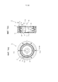
[0026]На фиг. 1 изображен вид с торца и продольный разрез сдвоенной волновой зубчатой передачи в соответствии с настоящим изобретением;[0026] FIG. 1 is an end view and a longitudinal section of a dual wave gear in accordance with the present invention;
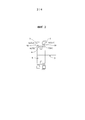
на фиг. 2 изображен схематический чертеж сдвоенной волновой зубчатой передачи, показанной на фиг. 1;in FIG. 2 is a schematic drawing of a dual wave gear train shown in FIG. one;
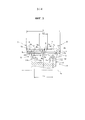
на фиг. 3 изображен частичный увеличенный разрез сдвоенной волновой зубчатой передачи, показанной на фиг. 1;in FIG. 3 is a partial enlarged sectional view of the dual wave gear of FIG. one;
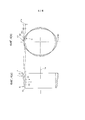
на фиг. 4 изображен схематический чертеж зубчатого колеса внешнего зацепления, показанного на фиг. 1, в изогнутом положении.in FIG. 4 is a schematic drawing of an external gear gear shown in FIG. 1, in a curved position.
ОСУЩЕСТВЛЕНИЕ ИЗОБРЕТЕНИЯDETAILED DESCRIPTION OF THE INVENTION
[0027] Далее приведено описание варианта осуществления сдвоенной волновой зубчатой передачи в соответствии с настоящим изобретением со ссылкой на сопроводительные чертежи.[0027] The following is a description of an embodiment of a dual wave gear in accordance with the present invention with reference to the accompanying drawings.
[0028] На фиг. 1(a) изображен вид с торца, демонстрирующий сдвоенную волновую зубчатую передачу (далее называемую просто «волновая зубчатая передача») в соответствии с вариантом осуществления настоящего изобретения, и на фиг. 1(b) изображен продольный разрез, демонстрирующий разрез участка вдоль линии b-b на фиг. 1(a). На фиг. 2 изображен схематический чертеж того же самого. Волновая зубчатая передача 1, используемая в качестве, например, зубчатого редуктора, содержит первое кольцевое жесткое зубчатое колесо 2 внутреннего зацепления, второе кольцевое жесткое зубчатое колесо 3 внутреннего зацепления, цилиндрическое гибкое зубчатое колесо 4 внешнего зацепления, состоящее из гибкого в радиальном направлении тонкостенного упругого тела, и генератор 5 волн с эллипсоидным контуром.[0028] In FIG. 1 (a) is an end view showing a dual wave gear (hereinafter referred to simply as a “wave gear”) in accordance with an embodiment of the present invention, and FIG. 1 (b) is a longitudinal sectional view showing a sectional view of a portion along line b-b in FIG. 1 (a). In FIG. 2 is a schematic drawing of the same. The
[0029] Первое и второе зубчатые колеса 2, 3 внутреннего зацепления расположены обеспечением соосного выравнивания друг с другом параллельно друг, и между ними образован зазор вдоль направления центральной оси 1а. В данном примере первое зубчатое колесо 2 внутреннего зацепления является зубчатым колесом внутреннего зацепления, расположенным с неподвижной стороны и закрепленным без возможности вращения, число первых внутренних зубьев 2а которого обозначено Zc1. Второе зубчатое колесо 3 внутреннего зацепления является зубчатым колесом внутреннего зацепления, расположенным с приводной стороны и поддерживаемым с возможностью вращения, число вторых внутренних зубьев 3а которого обозначено Zc2. Второе зубчатое колесо 3 внутреннего зацепления представляет собой элемент вывода замедленного вращения волновой зубчатой передачи 1.[0029] The first and second
[0030] Цилиндрическое зубчатое колесо 4 внешнего зацепления, расположено соосно внутри первого и второго зубчатых колес 2, 3 внутреннего зацепления. Зубчатое колесо 4 внешнего зацепления содержит цилиндрическое тело 6, представляющее собой гибкое в радиальном направлении тонкостенное упругое тело, первые наружные зубья 7 и вторые наружные зубья 8, выполненные на кольцевой наружной периферической поверхности цилиндрического тела 6, и зазор 9 (см. фиг. 3), образованный между наружными зубьями 7, 8 с обеих сторон и служащий в качестве просвета между инструментом и заготовкой. Первые наружные зубья 7 выполнены с одной стороны вдоль направления центральной оси 1а кольцевой наружной периферической поверхности цилиндрического тела 6, а вторые наружные зубья 8 выполнены с другой стороны вторых внутренних зубьев За кольцевой наружной периферической поверхности. Первые и вторые наружные зубья 7, 8 выполнены таким образом, что направление центральной оси 1а является направлением линии зуба.[0030] An external
[0031]В частности, первые наружные зубья 7 выполнены напротив первых внутренних зубьев 2а и выполнены с возможностью зацепления с первыми внутренними зубьями 2а, причем число первых наружных зубьев 7 обозначено Zf1. Вторые наружные зубья 8 выполнены напротив вторых внутренних зубьев 3а и выполнены с возможностью зацепления со вторыми внутренними зубьями 3а, причем число вторых наружных зубьев 8 обозначено Zf2. Числа Zf1, Zf2 зубьев отличаются друг от друга.[0031] In particular, the first
[0032] Генератор 5 волн содержит жесткий кулачок 11 с эллипсоидным контуром, а также первый волновой подшипник 12 и второй волновой подшипник 13, причем первый и второй волновые подшипники установлены на наружной периферической эллипсоидной поверхности жесткого кулачка 11. Первый и второй волновые подшипники образованы из шарикоподшипников.[0032] The
[0033] Генератор волн 5 вставлен во внутреннюю периферическую поверхность цилиндрического тела 6 зубчатого колеса 4 внешнего зацепления и вызывает изгиб цилиндрического тела 6 с получением эллипсоидной формы. В результате чего, первые и вторые наружные зубья 7, 8 также изгибаются с получением эллипсоидной формы. Зубчатое колесо 4 внешнего зацепления, изогнутое с получением эллипсоидной формы, входит в зацепление с первым и вторым зубчатыми колесами 2, 3 внутреннего зацепления в обоих конечных положениях вдоль большой оси Lmax эллипса. В частности, первые наружные зубья 7 входят в зацепление с первыми внутренними зубьями 2а в обоих конечных положениях вдоль большой оси эллипса, а вторые наружные зубья 8 входят в зацепление со вторыми внутренними зубьями 3а в обоих конечных положениях вдоль большой оси эллипса.[0033] The
[0034] Генератор 5 волн представляет собой элемент ввода вращения волновой зубчатой передачи 1. Жесткий кулачок 11 генератора 5 волн имеет отверстие 11 с для вала, в котором соосно установлен и надежно закреплен входной поворотный вал 10 (см. фиг. 2). Например, в отверстии 11 с может быть соосно установлен и надежно закреплен выходной вал электродвигателя. При вращении генератора 5 волн положения, в которых входят в зацепление первые наружные зубья 7 зубчатого колеса 4 внешнего зацепления и расположенные с неподвижной стороны первые внутренние зубья 2а, а также положения, в которых входят в зацепление вторые наружные зубья 8 зубчатого колеса 4 внешнего зацепления и расположенные с приводной стороны вторые внутренние зубья 3а, перемещаются вдоль окружного направления.[0034] The
[0035] Число Zf1 первых наружных зубьев 7 и число Zf2 вторых наружных зубьев 8 отличаются друг от друга; в данном примере число Zf2 вторых наружных зубьев больше. Число Zc1 первых внутренних зубьев 2а и число Zf1 первых наружных зубьев 7 также отличаются друг от друга; в данном примере число Zc1 первых внутренних зубьев 2а больше. Число Zc2 вторых внутренних зубьев 3а и число Zf2 вторых наружных зубьев 8 отличаются друг от друга; в данном примере число Zc2 вторых внутренних зубьев 3а меньше.[0035] The number Zf1 of the first
[0036] В данном примере зубчатое колесо 4 внешнего зацепления изгибается с получением эллипсоидной формы и входит в зацепление с зубчатыми колесами 2, 3 внутреннего зацепления в двух положениях вдоль окружного направления. Таким образом, разница между числом Zc1 первых внутренних зубьев 2а и числом Zf1 первых наружных зубьев 7 равна 2n1, где n1 - это положительное целое число. Разница между числом Zc2 вторых внутренних зубьев 3а и числом Zf2 вторых наружных зубьев 8 равна 2n2, где n2 - это положительное целое число.[0036] In this example, the
Zc1=Zf1+2n1 Zc1 = Zf1 + 2n 1
Zc2=Zf2-2n2 Zc2 = Zf2-2n 2
[0037] В конкретном примере числа зубьев установлены следующим образом (n1=n2=1):[0037] In a specific example, the number of teeth is set as follows (n 1 = n 2 = 1):
Zc1=62Zc1 = 62
Zf1=60Zf1 = 60
Zc2=62Zc2 = 62
Zf2=64Zf2 = 64
[0038]Передаточное отношение R1 между первым зубчатым колесом 2 внутреннего зацепления и первыми наружными зубьями 7, а также передаточное отношение R2 между вторым зубчатым колесом 3 внутреннего зацепления и вторыми наружными зубьями 8 соответственно заданы следующим образом:[0038] The gear ratio R1 between the
i1=1/R1=(Zf1-Zc1)/Zf1=(60-62)/60=-1/30i1 = 1 / R1 = (Zf1-Zc1) / Zf1 = (60-62) / 60 = -1 / 30
i2=1/R2=(Zf2-Zc2)/Zf2=(64-62)/64=1/32i2 = 1 / R2 = (Zf2-Zc2) / Zf2 = (64-62) / 64 = 1/32
Таким образом, R1=-30, a R2=32.Thus, R1 = -30, a R2 = 32.
[0039] Передаточное отношение R волновой зубчатой передачи 1 представлено следующей формулой, использующей значения передаточных отношений R1 и R2. Таким образом, в соответствии с настоящим изобретением может быть реализована волновая зубчатая передача, имеющая очень малое передаточное отношение (низкий коэффициент редукции) (отрицательное передаточное отношение означает, что вращение на выходе осуществляется в направлении, противоположном вращению на входе).[0039] The gear ratio R of the
R=(R1×R2-R1)/(-R1+R2)R = (R1 × R2-R1) / (- R1 + R2)
=(-30×32+30)/(30+32)= (- 30 × 32 + 30) / (30 + 32)
=-930/62= -930 / 62
=-15= -15
[0040] 3азор: просвет между инструментом и заготовкой[0040] Gap: clearance between tool and workpiece
На фиг. 3 изображен частичный увеличенный разрез волновой зубчатой передачи, показывающий зубчатое колесо 4 внешнего зацепления, а также первый и второй волновые подшипники 12 и 13 генератора 5 волн. Зазор 9, образованный между первыми и вторыми наружными зубьями 7, 8, служит в качестве просвета между инструментом и заготовкой для зуборезных фрез, используемых для нарезания первых и вторых наружных зубьев 7, 8.In FIG. 3 is a partial enlarged sectional view of a wave gear showing an
[0041] Далее сначала описаны первые и вторые наружные зубья 7 и 8. Поскольку первые и вторые внутренние зубья 2а и 3а имеют по существу одинаковую ширину зуба, то первые наружные зубья 7 и вторые наружные зубья 8, имеющие одинаковую ширину зуба, выполнены симметрично относительно центрального положения 6а по направлению линии зуба цилиндрического тела 6. В том случае, если первые и вторые внутренние зубья отличаются друг от друга по ширине зуба, первые и вторые наружные зубья 7 и 8 также будут отличаться по ширине зуба.[0041] The first and second
[0042] 3азор 9 имеет установленную ширину вдоль направления линии зуба; а самый глубокий участок, который представляет собой участок зазора 9, выполненный самым глубоким вдоль направления высоты зуба, образован в центральной части направления линии зуба. В настоящем изобретении самый глубокий участок 9а представляет собой участок, на котором центральная часть по направлению линии зуба задана прямой линией, проходящей параллельно направлению линии зуба, если смотреть со стороны направления толщины зуба. С двух концов самого глубокого участка 9а по направлению линии зуба плавно соединены вогнутая дугообразная кривая, которая задает внутреннюю торцевую поверхность 7а первых наружных зубьев 7 по направлению линии зуба, и вогнутая дугообразная кривая, которая задает внутреннюю торцевую поверхность 8а вторых наружных зубьев 8 по направлению линии зуба. Может быть также принята конфигурация, в которой самый глубокий участок 9а задан вогнутой дугообразной поверхностью, а две внутренние торцевые поверхности 7а, 8а заданы наклонными прямыми линиями. Кроме того, может быть принята конфигурация, в которой самый глубокий участок 9а задан прямой линией, а две внутренние торцевые поверхности 7а, 8а заданы наклонными прямыми линиями.[0042] The gap 9 has a predetermined width along the direction of the tooth line; and the deepest portion, which is the portion of the gap 9, made the deepest along the direction of the height of the tooth, is formed in the Central part of the direction of the line of the tooth. In the present invention, the
[0043] Ширина зазора 9 по направлению линии зуба в данном примере постепенно увеличивается от самого глубокого участка 9а вдоль направления высоты зуба. Максимальная ширина L1 по направлению линии зуба представляет собой расстояние вдоль направления линии зуба от внутреннего края 7b окружности вершин первых наружных зубьев 7 до внутреннего края 8b окружности вершин вторых наружных зубьев 8.[0043] The width of the gap 9 in the direction of the tooth line in this example is gradually increasing from the
[0044] Установлено соотношение[0044] The ratio is established
0,1L<L1<0,3L,0.1L <L1 <0.3L,
где L - ширина от наружного торца 7с первых наружных зубьев 7 по направлению линии зуба до наружного торца 8с вторых наружных зубьев 8 по направлению линии зуба, a L1 - максимальная ширина зазора 9 по направлению линии зуба.where L is the width from the outer end 7c of the first
[0045] Высота самого глубокого участка 9а зазора 9 задана следующим образом. Установлены соотношения[0045] The height of the
0,9h1<t1<l,3h1 и0.9h1 <t1 <l, 3h1 and
0,9h2<t2<l,3h2,0.9h2 <t2 <l, 3h2,
где h1 - высота зуба первых наружных зубьев 7, h2 - высота зуба вторых наружных зубьев 8, t1 - глубина по высоте зуба от вершины 7d зуба первых наружных зубьев 7 до самого глубокого участка 9а, и t2 - глубина по высоте зуба от вершины 8d зуба вторых наружных зубьев 8 до самого глубокого участка 9а.where h1 is the height of the tooth of the first
[004б] Более того, для зубчатого колеса 4 внешнего зацепления сдвоенной волновой зубчатой передачи 1 используются разные зуборезные фрезы для нарезания первых и вторых наружных зубьев. По этой причине зазор 9, служащий в качестве просвета между инструментом и заготовкой, образован в центральной части по направлению линии зуба зубчатого колеса 4 внешнего зацепления, а именно, между первыми и вторыми наружными зубьями 7 и 8.[004b] Moreover, for the
[0047] То, каким образом образован зазор 9, оказывает заметное воздействие на контакт первых наружных зубьев 7 с первыми внутренними зубьями 2а вдоль направления линии зуба, равно как и на распределение нагрузки по пятну контакта. Аналогично, то, каким образом образован зазор 9, оказывает заметное воздействие на контакт вторых наружных зубьев 8 со вторыми внутренними зубьями 3а вдоль направления линии зуба, равно как и на распределение нагрузки по пятну контакта.[0047] The manner in which the gap 9 is formed has a noticeable effect on the contact of the first
[0048] Ввиду вышеизложенного, максимальная ширина L1 зазора 9 установлена в пределах диапазона от 0,1 до 0,3 ширины L зубчатого колеса 4 внешнего зацепления, а максимальные значения глубины t1, t2 установлены в пределах диапазона от 0,9 до 1,3 высоты h1, h2 зуба первых и вторых наружных зубьев 7 и 8. Было подтверждено, что образование зазора 9 таким способом позволяет поддерживать равномерность распределения нагрузки по пятну контакта вдоль направления линии зуба первых и вторых наружных зубьев 7, 8, а также поддерживать удовлетворительное состояние контакта первых и вторых наружных зубьев 7, 8 с первыми и вторыми внутренними зубьями 2а, 3а в каждом положении по направлению линии зуба.[0048] In view of the foregoing, the maximum width L1 of the gap 9 is set within the range from 0.1 to 0.3 of the width L of the
[0049] Соответственно, можно реализовать волновую зубчатую передачу с передаточным отношением менее 30, а также с высокой усталостной прочностью корня зуба и большой нагрузочной способностью.[0049] Accordingly, it is possible to implement a wave gear transmission with a gear ratio of less than 30, as well as with high fatigue strength of the tooth root and high load capacity.
[0050] [Расстояние между центрами шариков подшипников в волновом генераторе][0050] [The distance between the centers of the balls of bearings in the wave generator]
Далее со ссылками на фиг. 3 описано расстояние между центрами шариков первого и второго волновых подшипников 12, 13.Next, with reference to FIG. 3, the distance between the centers of the balls of the first and
[0051] В жестком кулачке 11 генератора 5 волн первая наружная периферическая поверхность 11а фиксированной ширины с эллипсоидным контуром выполнена с одной стороны по направлению центральной оси, а вторая наружная поверхность 11b фиксированной ширины с эллипсоидным контуром выполнена с другой стороны по направлению центральной оси. Первая наружная периферическая поверхность 11а и вторая наружная периферическая поверхность 11b представляют собой эллипсоидные наружные периферические поверхности, имеющие одинаковую форму и одинаковую фазу.[0051] In the
[0052] Первый волновой подшипник 12 установлен на первой наружной периферической поверхности 11а изогнутым с получением эллипсоидной формы, а второй волновой подшипник 13 установлен на второй наружной периферической поверхности 11b изогнутым с получением эллипсоидной формы. Первый и второй волновые подшипники 12, 13 имеют одинаковый размер.[0052] The first wave bearing 12 is mounted on the first outer
[0053] Центры 12а, 13а первого волнового подшипника 12 и второго волнового подшипника 13 равноудалены, вдоль направления ширины зуба, от центрального положения ба по направлению линии зуба на зубчатом колесе 4 внешнего зацепления. Расстояние между центрами шариков подшипников установлено таким образом, что оно увеличивается соответственно при увеличении максимальной ширины L1 зазора 9. Кроме того, межцентровое расстояние Lo установлено таким образом, чтобы находиться в пределах диапазона, заданного следующей формулой, где Lo - расстояние между центрами шариков подшипников.[0053] The
0,35L<Lo<0,7L0.35L <Lo <0.7L
[0054] B известном уровне техники применяют генератор волн, содержащий два ряда шариков для подшипников, для увеличения площади, на которую опирается зубчатое колесо внешнего зацепления. Два ряда шариков для подшипников были расположены относительно центральной части по направлению ширины зуба зубчатого колеса внешнего зацепления, не учитывая межцентровое расстояние.[0054] In the prior art, a wave generator comprising two rows of balls for bearings is used to increase the area on which an external gear is supported. Two rows of balls for bearings were located relative to the central part in the direction of the width of the tooth of the external gear tooth, not taking into account the center distance.
[0055] В настоящем примере межцентровое расстояние Lo между двумя рядами волновых подшипников 12, 13 увеличено с тем, чтобы можно было повысить жесткость опоры первых и вторых наружных зубьев 7, 8, отличающихся друг от друга числом, и улучшить контакт каждого из наружных зубьев 7, 8 с внутренними зубьями 2а, 3а в каждом положении по направлению линии зуба. В частности, как описано выше, принята конфигурация, в которой межцентровое расстояние Lo удлиняется (увеличивается) в соответствии с увеличением в направлении линии зуба максимальной длины L1 зазора 9, образованного между первыми и вторыми наружными зубьями 7, 8 и служащего в качестве просвета между инструментом и заготовкой. Величина увеличения межцентрового расстояния Lo установлена в диапазоне 0,35-0,7 ширины L зубчатого колеса 4 внешнего зацепления.[0055] In the present example, the center-to-center distance Lo between the two rows of
[005б] Это позволяет разместить первый и второй волновые подшипники 12, 13 таким образом, чтобы центры шариков подшипников имели подходящее расположение по направлению линии зуба относительно первых и вторых наружных зубьев 7, 8 в соответствии с шириной образованного зазора 9. Это позволяет обеспечить надежную поддержку первых и вторых наружных зубьев 7, 8 с использованием первых и вторых волновых подшипников 12, 13 в каждом положении по направлению линии зуба первых и вторых наружных зубьев 7, 8 (т.е. увеличить опорную жесткость генератора 5 волн).[005b] This allows you to place the first and
[0057] В результате, можно улучшить пятно контакта первых и вторых наружных зубьев 7, 8 в каждом положении по направлению линии зуба и повысить их усталостную прочность корня зуба. Кроме того, можно усреднить распределение нагрузки на шарики каждого волнового подшипника 12, 13 генератора 5 волн и снизить максимальную нагрузку и, тем самым, увеличить срок службы генератора 5 волн.[0057] As a result, the contact spot of the first and second
[0058] Величина, на которую изгибается зубчатое колесо внешнего зацепления[0058] The amount by which the external gear is bent
В настоящем примере первые и вторые наружные зубья 7, 8 зубчатого колеса 4 внешнего зацепления подвергаются изгибу с получением эллипсоидной формы генератором 5 волн, имеющим два ряда волновых подшипников 12, 13. m1 - модуль первых наружных зубьев 7, и m2 - модуль вторых наружных зубьев 8. 2n1 - разница в числе зубьев между первыми наружными зубьями 7 и первыми внутренними зубьями 2a, и 2n2 - разница в числе зубьев между вторыми наружными зубьями 8 и вторыми внутренними зубьями 3а.In the present example, the first and second
[0059] Теоретическое значение d1 величины, на которую первые наружные зубья 7 изогнуты в радиальном направлении в местах положения большой оси Lmax, и теоретическое значение d2 величины, на которую вторые наружные зубья 8 изогнуты в радиальном направлении при изгибе наружных зубьев с получением эллипсоидной формы, соответственно представлены следующими соотношениями[0059] The theoretical value d 1 of the value by which the first
d1=m1n1;d 1 = m 1 n 1 ;
d2=m2n2.d 2 = m 2 n 2 .
[0060]В настоящем примере величина d1a, на которую первые наружные зубья 7 изогнуты в радиальном направлении генератором 5 волн, больше теоретического значения d1. Аналогичным образом, величина d2a, на которую вторые наружные зубья 8 изогнуты в радиальном направлении генератором 5 волн, больше теоретического значения d2. В частности, в настоящем примере величины d1a и d2a радиального изгиба заданы в пределах следующих диапазонов:[0060] In the present example, the value of d 1a by which the first
d1a=ωd1,d 1a = ωd 1 ,
d2a=ωd2,d 2a = ωd 2 ,
![]()
![]()
[0061] На фиг. 4 в преувеличенной форме изображен схематический чертеж зубчатого колеса 4 внешнего зацепления в изогнутом положении. Как показано на фиг. 4, окружность С обода в нейтральном положении представляет собой окружность, проходящую через центр толщины цилиндрического тела 6 (обод у корня зуба) в положении, в котором зубчатое колесо 4 внешнего зацепления является идеально круглым перед изгибом с получением эллипсоидной формы. Окружность С обода в нейтральном положении деформируется с получением эллипсоидной формы вследствие изгиба зубчатого колеса 4 внешнего зацепления с получением эллипсоидной формы. Указанную деформированную окружность называют «эллипсоидной кривой С1 обода в нейтральном положении». Величина d, на которую зубчатое колесо 4 внешнего зацепления изогнуто в радиальном направлении, представляет собой разницу между радиусом большой оси Lmax эллипсоидной кривой С1 обода в нейтральном положении и радиусом окружности С обода в нейтральном положении.[0061] FIG. 4, an exaggerated form depicts a schematic diagram of an
[0062] В настоящем примере величина радиального изгиба первых наружных зубьев 7 больше величины радиального изгиба вторых наружных зубьев 8. Соответственно, величина изгиба зубчатого колеса 4 внешнего зацепления увеличивается от наружного торца 8 с второго наружного колеса 8 к наружному торцу 7 с первого наружного колеса 7 примерно пропорционально расстоянию от наружного торца 8 с в поперечном сечении, включающем большую ось Umax, как показано в преувеличенной форме на фиг. 4. Вышеописанные величины d1a и d2a радиального изгиба представляют собой средние величины изгиба первых и вторых наружных зубьев 7 и 8 соответственно. Они приблизительно равны величинам изгиба в центральных положениях первых и вторых наружных зубьев по направлению линии зуба (разница между радиусами эллипсоидных кривых C1, С2 обода в нейтральном положении и окружности С обода в нейтральном положении).[0062] In the present example, the radial bending value of the first
[0063] Величины радиального изгиба первых и вторых наружных зубьев 7 и 8, отличающихся числом, больше теоретических значений, как описано выше. Было подтверждено, что наружные зубья 7 и 8 могут быть надлежащим образом введены в зацепление с соответствующими зубчатыми колесами внутреннего зацепления, и может быть увеличена износоустойчивость и усталостная прочность корня зуба первых и вторых наружных зубьев. Кроме того, было подтверждено, что может быть обеспечено равномерное распределение нагрузки на шарики двух рядов волновых подшипников 12 и 13 для поддержки первых и вторых наружных зубьев 7 и 8, и срок службы волновых подшипников 12 и 13 может быть увеличен.[0063] The radial bending values of the first and second
[0064] Другие варианты осуществления изобретения В примере, описанном выше, первое зубчатое колесо 2 внутреннего зацепления выполнено как зубчатое колесо внутреннего зацепления, расположенное с неподвижной стороны, а второе зубчатое колесо 3 внутреннего зацепления выполнено как зубчатое колесо внутреннего зацепления, расположенное с приводной стороны. И наоборот, вместо этого возможно выполнить первое зубчатое колесо 2 внутреннего зацепления как зубчатое колесо внутреннего зацепления, расположенное с приводной стороны, а второе зубчатое колесо 3 внутреннего зацепления выполнить как зубчатое колесо внутреннего зацепления, расположенное с неподвижной стороны.[0064] Other Embodiments In the example described above, the first
Claims (51)
Applications Claiming Priority (3)
| Application Number | Priority Date | Filing Date | Title |
|---|---|---|---|
| JP2014149372A JP6370624B2 (en) | 2014-07-23 | 2014-07-23 | Dual type wave gear device |
| JP2014-149372 | 2014-07-23 | ||
| PCT/JP2015/069244 WO2016013380A1 (en) | 2014-07-23 | 2015-07-03 | Dual-type wave gear device |
Publications (1)
| Publication Number | Publication Date |
|---|---|
| RU2658846C1 true RU2658846C1 (en) | 2018-06-25 |
Family
ID=55162912
Family Applications (1)
| Application Number | Title | Priority Date | Filing Date |
|---|---|---|---|
| RU2016148940A RU2658846C1 (en) | 2014-07-23 | 2015-07-03 | Dual harmonic gear drive |
Country Status (10)
| Country | Link |
|---|---|
| US (1) | US10309513B2 (en) |
| EP (1) | EP3173659B1 (en) |
| JP (1) | JP6370624B2 (en) |
| KR (1) | KR101918011B1 (en) |
| CN (1) | CN106536976B (en) |
| BR (1) | BR112017000370B1 (en) |
| MX (1) | MX2017001006A (en) |
| RU (1) | RU2658846C1 (en) |
| TW (1) | TWI608185B (en) |
| WO (1) | WO2016013380A1 (en) |
Families Citing this family (5)
| Publication number | Priority date | Publication date | Assignee | Title |
|---|---|---|---|---|
| CN107387725A (en) * | 2017-08-10 | 2017-11-24 | 金明必 | Flexible gear and its component, decelerator and speed reducing ratio algorithm using the component |
| JP6912989B2 (en) * | 2017-09-27 | 2021-08-04 | 住友重機械工業株式会社 | Flexible meshing gear device |
| JP6552571B2 (en) * | 2017-09-29 | 2019-07-31 | 株式会社ハーモニック・ドライブ・システムズ | Dual type wave gear device |
| JP2019105311A (en) * | 2017-12-13 | 2019-06-27 | 本田技研工業株式会社 | Force distribution device |
| CN112145650B (en) * | 2020-09-28 | 2022-03-25 | 珠海格力电器股份有限公司 | Rigidity compensation device, harmonic speed reducer and robot |
Citations (7)
| Publication number | Priority date | Publication date | Assignee | Title |
|---|---|---|---|---|
| SU301479A1 (en) * | WAVE GEAR TRANSFER | |||
| SU1137269A1 (en) * | 1980-06-30 | 1985-01-30 | МВТУ им.Н.Э.Баумана | Twin wave gearing |
| JPH02275147A (en) * | 1989-04-17 | 1990-11-09 | Harmonic Drive Syst Ind Co Ltd | Wave motion gearing |
| UA78075C2 (en) * | 2005-02-07 | 2007-02-15 | Robert Vachahan Ambartsumiants | Method for determination of teeth module of involute cylindrical toothed wheels |
| JP2011112214A (en) * | 2009-11-30 | 2011-06-09 | Sumitomo Heavy Ind Ltd | Flexible meshing-type gear device, and method for manufacturing external gear thereof |
| JP2013119919A (en) * | 2011-12-08 | 2013-06-17 | Sumitomo Heavy Ind Ltd | Flexible meshing type gear device |
| US8656800B2 (en) * | 2008-06-24 | 2014-02-25 | Korea Institute Of Science And Technology | Harmonic drive using profile shifted gear |
Family Cites Families (14)
| Publication number | Priority date | Publication date | Assignee | Title |
|---|---|---|---|---|
| JPS6491151A (en) | 1987-10-02 | 1989-04-10 | Ricoh Kk | Device for operating copying machine |
| JPH0451235Y2 (en) | 1987-12-10 | 1992-12-02 | ||
| JP2007303592A (en) * | 2006-05-12 | 2007-11-22 | Honda Motor Co Ltd | Harmonic drive |
| US8028603B2 (en) | 2007-12-04 | 2011-10-04 | Harmonic Drive Systems Inc. | Method for setting gear tooth profile in flat wave gear device on side where gears have same number of teeth |
| JP4877837B2 (en) * | 2007-12-04 | 2012-02-15 | 株式会社ハーモニック・ドライブ・システムズ | Tooth profile setting method for the same number of teeth side gear of flat type wave gear device |
| JP5064300B2 (en) * | 2008-05-28 | 2012-10-31 | 株式会社ハーモニック・ドライブ・システムズ | Wave gear type linear motion mechanism |
| JP4948479B2 (en) * | 2008-06-26 | 2012-06-06 | 株式会社ハーモニック・ドライブ・システムズ | Compound wave gear reducer |
| JP5275150B2 (en) * | 2009-06-23 | 2013-08-28 | 株式会社ハーモニック・ドライブ・システムズ | Wave gear device |
| JP5256249B2 (en) * | 2010-06-18 | 2013-08-07 | 住友重機械工業株式会社 | Bending gear system |
| TWI412674B (en) * | 2010-11-17 | 2013-10-21 | Ind Tech Res Inst | Reducer structure and its wave gear drive |
| US9425712B2 (en) | 2011-09-16 | 2016-08-23 | Harmonic Drive Systems Inc. | Vibration power-generating strain wave gearing |
| JP5833480B2 (en) | 2012-03-21 | 2015-12-16 | 本田技研工業株式会社 | Wave gear device and walking assist device |
| US9360098B2 (en) * | 2013-10-29 | 2016-06-07 | Roopnarine | Strain wave drive with improved performance |
| JP6218692B2 (en) * | 2014-07-23 | 2017-10-25 | 株式会社ハーモニック・ドライブ・システムズ | Dual type wave gear device |
-
2014
- 2014-07-23 JP JP2014149372A patent/JP6370624B2/en active Active
-
2015
- 2015-07-03 RU RU2016148940A patent/RU2658846C1/en active
- 2015-07-03 MX MX2017001006A patent/MX2017001006A/en unknown
- 2015-07-03 KR KR1020167035464A patent/KR101918011B1/en active IP Right Grant
- 2015-07-03 CN CN201580038728.6A patent/CN106536976B/en active Active
- 2015-07-03 US US15/327,866 patent/US10309513B2/en active Active
- 2015-07-03 WO PCT/JP2015/069244 patent/WO2016013380A1/en active Application Filing
- 2015-07-03 EP EP15824221.4A patent/EP3173659B1/en active Active
- 2015-07-03 BR BR112017000370-8A patent/BR112017000370B1/en active IP Right Grant
- 2015-07-20 TW TW104123405A patent/TWI608185B/en active
Patent Citations (7)
| Publication number | Priority date | Publication date | Assignee | Title |
|---|---|---|---|---|
| SU301479A1 (en) * | WAVE GEAR TRANSFER | |||
| SU1137269A1 (en) * | 1980-06-30 | 1985-01-30 | МВТУ им.Н.Э.Баумана | Twin wave gearing |
| JPH02275147A (en) * | 1989-04-17 | 1990-11-09 | Harmonic Drive Syst Ind Co Ltd | Wave motion gearing |
| UA78075C2 (en) * | 2005-02-07 | 2007-02-15 | Robert Vachahan Ambartsumiants | Method for determination of teeth module of involute cylindrical toothed wheels |
| US8656800B2 (en) * | 2008-06-24 | 2014-02-25 | Korea Institute Of Science And Technology | Harmonic drive using profile shifted gear |
| JP2011112214A (en) * | 2009-11-30 | 2011-06-09 | Sumitomo Heavy Ind Ltd | Flexible meshing-type gear device, and method for manufacturing external gear thereof |
| JP2013119919A (en) * | 2011-12-08 | 2013-06-17 | Sumitomo Heavy Ind Ltd | Flexible meshing type gear device |
Also Published As
| Publication number | Publication date |
|---|---|
| BR112017000370B1 (en) | 2023-02-14 |
| TW201610324A (en) | 2016-03-16 |
| MX2017001006A (en) | 2017-09-01 |
| EP3173659A1 (en) | 2017-05-31 |
| JP6370624B2 (en) | 2018-08-08 |
| JP2016023744A (en) | 2016-02-08 |
| CN106536976A (en) | 2017-03-22 |
| EP3173659B1 (en) | 2021-01-27 |
| US10309513B2 (en) | 2019-06-04 |
| CN106536976B (en) | 2019-05-17 |
| US20170211679A1 (en) | 2017-07-27 |
| BR112017000370A2 (en) | 2018-03-13 |
| TWI608185B (en) | 2017-12-11 |
| WO2016013380A1 (en) | 2016-01-28 |
| KR20170010320A (en) | 2017-01-26 |
| EP3173659A4 (en) | 2018-07-11 |
| KR101918011B1 (en) | 2018-11-13 |
Similar Documents
| Publication | Publication Date | Title |
|---|---|---|
| RU2668455C2 (en) | Dual harmonic gear drive | |
| RU2659187C1 (en) | Dual harmonic gear drive | |
| RU2655578C1 (en) | Dual wave gear transmission | |
| RU2658846C1 (en) | Dual harmonic gear drive | |
| KR100988215B1 (en) | Harmonic drive using profile shifted gear | |
| JP6351724B2 (en) | Flat wave gear device | |
| RU2659276C1 (en) | Dual harmonic gear drive | |
| RU2659196C1 (en) | Dual harmonic gear drive | |
| RU2714353C1 (en) | Double-shaft transmission | |
| KR20090087612A (en) | Harmonic drive | |
| CN114370486B (en) | Three-wave cam wave generator on harmonic reducer and harmonic reducer |