BR112017000374B1 - DUAL TYPE TENSION WAVE GEAR - Google Patents
DUAL TYPE TENSION WAVE GEAR Download PDFInfo
- Publication number
- BR112017000374B1 BR112017000374B1 BR112017000374-0A BR112017000374A BR112017000374B1 BR 112017000374 B1 BR112017000374 B1 BR 112017000374B1 BR 112017000374 A BR112017000374 A BR 112017000374A BR 112017000374 B1 BR112017000374 B1 BR 112017000374B1
- Authority
- BR
- Brazil
- Prior art keywords
- teeth
- tooth
- outer teeth
- wave
- gear
- Prior art date
Links
Images


Classifications
-
- F—MECHANICAL ENGINEERING; LIGHTING; HEATING; WEAPONS; BLASTING
- F16—ENGINEERING ELEMENTS AND UNITS; GENERAL MEASURES FOR PRODUCING AND MAINTAINING EFFECTIVE FUNCTIONING OF MACHINES OR INSTALLATIONS; THERMAL INSULATION IN GENERAL
- F16H—GEARING
- F16H49/00—Other gearings
- F16H49/001—Wave gearings, e.g. harmonic drive transmissions
-
- F—MECHANICAL ENGINEERING; LIGHTING; HEATING; WEAPONS; BLASTING
- F16—ENGINEERING ELEMENTS AND UNITS; GENERAL MEASURES FOR PRODUCING AND MAINTAINING EFFECTIVE FUNCTIONING OF MACHINES OR INSTALLATIONS; THERMAL INSULATION IN GENERAL
- F16C—SHAFTS; FLEXIBLE SHAFTS; ELEMENTS OR CRANKSHAFT MECHANISMS; ROTARY BODIES OTHER THAN GEARING ELEMENTS; BEARINGS
- F16C19/00—Bearings with rolling contact, for exclusively rotary movement
- F16C19/02—Bearings with rolling contact, for exclusively rotary movement with bearing balls essentially of the same size in one or more circular rows
- F16C19/04—Bearings with rolling contact, for exclusively rotary movement with bearing balls essentially of the same size in one or more circular rows for radial load mainly
- F16C19/06—Bearings with rolling contact, for exclusively rotary movement with bearing balls essentially of the same size in one or more circular rows for radial load mainly with a single row or balls
-
- F—MECHANICAL ENGINEERING; LIGHTING; HEATING; WEAPONS; BLASTING
- F16—ENGINEERING ELEMENTS AND UNITS; GENERAL MEASURES FOR PRODUCING AND MAINTAINING EFFECTIVE FUNCTIONING OF MACHINES OR INSTALLATIONS; THERMAL INSULATION IN GENERAL
- F16H—GEARING
- F16H1/00—Toothed gearings for conveying rotary motion
- F16H1/28—Toothed gearings for conveying rotary motion with gears having orbital motion
- F16H1/32—Toothed gearings for conveying rotary motion with gears having orbital motion in which the central axis of the gearing lies inside the periphery of an orbital gear
-
- F—MECHANICAL ENGINEERING; LIGHTING; HEATING; WEAPONS; BLASTING
- F16—ENGINEERING ELEMENTS AND UNITS; GENERAL MEASURES FOR PRODUCING AND MAINTAINING EFFECTIVE FUNCTIONING OF MACHINES OR INSTALLATIONS; THERMAL INSULATION IN GENERAL
- F16H—GEARING
- F16H55/00—Elements with teeth or friction surfaces for conveying motion; Worms, pulleys or sheaves for gearing mechanisms
- F16H55/02—Toothed members; Worms
- F16H55/14—Construction providing resilience or vibration-damping
- F16H55/16—Construction providing resilience or vibration-damping relating to teeth only
-
- F—MECHANICAL ENGINEERING; LIGHTING; HEATING; WEAPONS; BLASTING
- F16—ENGINEERING ELEMENTS AND UNITS; GENERAL MEASURES FOR PRODUCING AND MAINTAINING EFFECTIVE FUNCTIONING OF MACHINES OR INSTALLATIONS; THERMAL INSULATION IN GENERAL
- F16C—SHAFTS; FLEXIBLE SHAFTS; ELEMENTS OR CRANKSHAFT MECHANISMS; ROTARY BODIES OTHER THAN GEARING ELEMENTS; BEARINGS
- F16C2370/00—Apparatus relating to physics, e.g. instruments
-
- F—MECHANICAL ENGINEERING; LIGHTING; HEATING; WEAPONS; BLASTING
- F16—ENGINEERING ELEMENTS AND UNITS; GENERAL MEASURES FOR PRODUCING AND MAINTAINING EFFECTIVE FUNCTIONING OF MACHINES OR INSTALLATIONS; THERMAL INSULATION IN GENERAL
- F16H—GEARING
- F16H49/00—Other gearings
- F16H49/001—Wave gearings, e.g. harmonic drive transmissions
- F16H2049/003—Features of the flexsplines therefor
Landscapes
- Engineering & Computer Science (AREA)
- General Engineering & Computer Science (AREA)
- Mechanical Engineering (AREA)
- Retarders (AREA)
- Gears, Cams (AREA)
Abstract
Trata-se de uma engrenagem externamente dentada de uma engrenagem com onda de tensão do tipo duplo, dotada de primeiros e segundos dentes externos (7, 8) que têm diferentes números de dentes. Os primeiros e segundos dentes externos (7, 8) são flexionados por um gerador de onda pela mesma quantidade de flexão, em um formato de elipse. O ângulo de pressão médio (a1) de seções de superfície de dente principal de perfis de dente (70) dos primeiros dentes externos (7) que têm um número de dentes baixo é menos agudo que o ângulo de pressão médio (a2) de seções de superfície de dente principal de perfis de dente (80) dos segundos dentes externos (8) que têm um número de dentes alto. Consequentemente, uma engrenagem com onda de tensão do tipo duplo pode ser alcançada, com a qual os primeiros e os segundos dentes externos que têm diferentes números de dentes podem ser adequadamente flexionados para formar excelentes estados de entrelaçamento com respectivas engrenagens internamente dentadas.It is an externally toothed gear of a double type stress wave gear having first and second external teeth (7, 8) having different numbers of teeth. The first and second outer teeth (7, 8) are flexed by a wave generator by the same amount of flexion, in an ellipse shape. The average pressure angle (a1) of main tooth surface sections of tooth profiles (70) of the first outer teeth (7) that have a low number of teeth is less acute than the average pressure angle (a2) of sections main tooth surface of tooth profiles (80) of the second outer teeth (8) having a high number of teeth. Consequently, a double-type stress wave gearing can be achieved, with which the first and second outer teeth having different numbers of teeth can be suitably flexed to form excellent meshing states with respective internally toothed gears.
Description
[0001] A presente invenção refere-se a uma engrenagem com onda de tensão que tem um par de engrenagens internamente dentadas, uma engrenagem externamente dentada cilíndrica com capacidade de se flexionar em uma direção radial, e um gerador de onda.[0001] The present invention relates to a voltage wave gear having a pair of internally toothed gears, a cylindrical externally toothed gear capable of flexing in a radial direction, and a wave generator.
[0002] As engrenagens com onda de tensão que têm engrenagens externamente dentadas cilíndricas são tipicamente dotadas de uma engrenagem internamente dentada de lado estacionário presa com a finalidade de não girar, um gerador de onda que é um elemento de inserção de rotação, uma engrenagem internamente dentada de lado de acionamento que é um elemento de emissão de rotação reduzida, e uma engrenagem externamente dentada cilíndrica com capacidade de se flexionar na direção radial e entrelaçar com a engrenagem internamente dentada de lado estacionário e a engrenagem internamente dentada de lado de acionamento. Em engrenagens com onda de tensão típicas, a engrenagem externamente dentada é provocada a se flexionar em um formato de elipse, em que engrenagem externamente dentada flexionada em formato de elipse entrelaça com as engrenagens internamente dentada de lado de acionamento e de lado estacionário em ambas as posições de extremidade ao longo do eixo geométrico principal do formato de elipse.[0002] Stress wave gears that have cylindrical external toothed gears are typically provided with an internally toothed stationary-side gear attached for non-turning purposes, a wave generator that is a rotation insert element, an internally geared drive side gear which is a low speed emitting element, and a cylindrical externally toothed gear capable of flexing in the radial direction and meshing with the stationary side internally toothed gear and the driving side internally toothed gear. In typical stress wave gears, the externally toothed gear is caused to flex into an elliptical shape, where the externally toothed gear flexed into an ellipse meshes with the driving-side and stationary-side internally toothed gears on both sides. endpoint positions along the major axis of the ellipse shape.
[0003] Os Documentos de Patente 1 e 4 revelam engrenagens com onda de tensão típicas nas quais o número de dentes da engrenagem internamente dentada de lado estacionário é duas vezes maior do que o da engrenagem externamente dentada, e o número de dentes da engrenagem internamente dentada de lado de acionamento é igual ao da engrenagem externamente dentada. No Documento de Patente 1, os dentes externos da engrenagem externamente dentada são bisseccionados na porção central de direção de traço de dente dos mesmos, em que uma das porções de dente externo tem capacidade de entrelaçar com a engrenagem internamente dentada de lado estacionário, e a outra das porções de dente externo tem capacidade de entrelaçar com a engrenagem internamente dentada de lado de acionamento. O Documento de Patente 4 indica que a espessura de parede de aro da engrenagem externamente dentada afeta dramaticamente a resistência à fadiga de fundo de dente da engrenagem externamente dentada.[0003]
[0004] Nas engrenagens com onda de tensão reveladas nos Documentos de Patente 1 e 4, quando o gerador de onda gira, a engrenagem externamente dentada gira mais lentamente em uma razão de velocidade que corresponde à diferença no número de dentes em relação à engrenagem internamente dentada de lado estacionário. A rotação reduzida da engrenagem externamente dentada é emitida a partir da engrenagem internamente dentada de lado de acionamento, que gira integralmente com a engrenagem externamente dentada.[0004] In the stress wave gears disclosed in
[0005] O Documento de Patente 2 revela uma engrenagem com onda de tensão na qual o número de dentes da engrenagem internamente dentada de lado estacionário é duas vezes maior que o da engrenagem externamente dentada, e o número de dentes da engrenagem internamente dentada de lado de acionamento é duas vezes menor que o da engrenagem externamente dentada. Nessa engrenagem com onda de tensão, quando o gerador de onda gira, a engrenagem externamente dentada gira mais lentamente em uma razão de velocidade que corresponde à diferença no número de dentes em relação à engrenagem internamente dentada de lado estacionário. A rotação da engrenagem externamente dentada é aumentada em uma razão de velocidade que corresponde à diferença em número e dentes entre a engrenagem externamente dentada e a engrenagem internamente dentada de lado de acionamento, e é emitida a partir da engrenagem internamente dentada de lado de acionamento. A rotação emitida a partir da engrenagem internamente dentada de lado de acionamento é reduzida a uma razão de velocidade de menos que 50 em relação à rotação inserida no gerador de onda.[0005]
[0006] Os Documentos de Patente 2 e 3 revelam engrenagens com onda de tensão que têm geradores de onda que têm duas fileiras de mancais esféricos. Esse tipo de gerador de onda é configurado a partir de um plugue rígido que tem uma superfície periférica externa de contorno em elipse, e duas fileiras de mancais esféricos encaixados na superfície periférica externa. A engrenagem internamente dentada flexível é pressionada radialmente para fora pelas duas porções de extremidade de eixo geométrico principal das superfícies periféricas externas dos traços externos flexionados em forma de elipse dos mancais esféricos, e o entrelaçamento da engrenagem internamente dentada flexível em relação à primeira e à segunda engrenagens internamente dentadas rígidas é sustentado.[0006]
[0007] Documento de Patente 1: JP-A2011-112214[0007] Patent Document 1: JP-A2011-112214
[0008] Documento de Patente 2: JP-A02-275147[0008] Patent Document 2: JP-A02-275147
[0009] Documento de Patente 3: JP-U01-91151[0009] Patent Document 3: JP-U01-91151
[0010] Documento de Patente 4: 2008-180259[0010] Patent Document 4: 2008-180259
[0011] Considera-se que, na engrenagem externamente dentada usada no presente documento, os primeiros dentes com capacidade de entrelaçar com uma primeira engrenagem internamente dentada e os segundos dentes com capacidade de entrelaçar com uma outra segunda engrenagem internamente dentada são formados na superfície periférica externa de um corpo cilíndrico radialmente flexível, em que os segundos dentes diferem em número dos primeiros dentes. A adoção de tal configuração possibilita reduzir ou aumentar a velocidade de rotação entre os primeiros dentes externos e uma primeira engrenagem internamente dentada, e reduzir ou aumentar a velocidade de rotação entre os segundos dentes externos e uma segunda engrenagem internamente dentada, de uma maneira similar como na engrenagem com onda de tensão revelada no Documento de Patente 2. Consequentemente, é possível realizar uma engrenagem com onda de tensão que tem uma razão de engrenagem menor do que 50. Adicionalmente, essa configuração permite que uma engrenagem com onda de tensão que tem uma razão de velocidade menor que 50 seja projetada com um grau de liberdade maior do que na engrenagem com onda de tensão revelada do Documento de Patente 2.[0011] It is considered that, in the externally toothed gear used herein, the first teeth capable of meshing with a first internally toothed gear and the second teeth capable of meshing with another second internally toothed gear are formed on the peripheral surface external part of a radially flexible cylindrical body, in which the second teeth differ in number from the first teeth. The adoption of such a configuration makes it possible to reduce or increase the speed of rotation between the first external teeth and a first internally toothed gear, and to reduce or increase the speed of rotation between the second external teeth and a second internally toothed gear, in a similar manner as in the stress wave gear disclosed in
[0012] No presente relatório descritivo, uma engrenagem com onda de tensão que tem uma engrenagem externamente dentada na qual os primeiros e segundos dentes externos diferem número são formados na superfície periférica externa de um corpo cilíndrico flexível é chamada de "engrenagem com onda de tensão de tipo duplo".[0012] In the present specification, a stress wave gear having an externally toothed gear in which the first and second external teeth differ in number are formed on the outer peripheral surface of a flexible cylindrical body is called a "stress wave gear double type".
[0013] Em uma engrenagem com onda de tensão de tipo duplo, os primeiros dentes externos e os segundos dentes externos de uma engrenagem externamente dentada são formados na superfície periférica externa de um corpo cilíndrico compartilhado, e as partes de aro de fundo de dente dos primeiros e dos segundos dentes externos são conectadas entre si. Quando o corpo cilíndrico é provocado pelo gerador de onda a flexionar em um formato de elipse, os primeiros e segundos dentes externos, que diferem em número, respectivamente, se entrelaçam com engrenagens internamente dentadas.[0013] In a double-type stress wave gear, the first outer teeth and the second outer teeth of an externally toothed gear are formed on the outer peripheral surface of a shared cylindrical body, and the tooth bottom rim parts of the first and second outer teeth are connected to each other. When the cylindrical body is caused by the wave generator to flex into an elliptical shape, the first and second outer teeth, which differ in number respectively, interlock with internally toothed gears.
[0014] Em casos em que a engrenagem externamente dentada é provocada pelo gerador de onda a flexionar em um formato de elipse, os primeiros e os segundos dentes externos formados na engrenagem externamente dentada flexionam pela mesma quantidade na direção radial. Os primeiros e os segundos dentes externos diferem em termos de módulo bem como número. A quantidade pela qual os primeiros dentes externos são flexionados para terem capacidade de entrelaçar satisfatoriamente com os dentes internos da primeira engrenagem internamente dentada e a quantidade pela qual os segundos dentes externos são flexionados para terem capacidade de entrelaçar satisfatoriamente com os dentes internos da segunda engrenagem internamente dentada diferem entre si.[0014] In cases where the externally toothed gear is caused by the wave generator to flex in an elliptical shape, the first and second external teeth formed on the externally toothed gear flex by the same amount in the radial direction. The first and second external teeth differ in terms of module as well as number. The amount by which the first outer teeth are flexed to be able to mesh satisfactorily with the inner teeth of the first internally toothed gear and the amount by which the second outer teeth are flexed to be able to mesh satisfactorily with the inner teeth of the second gear internally toothed differ from each other.
[0015] Portanto, mesmo quando os dentes externos em um lado podem entrelaçar satisfatoriamente com os dentes internos, o grau de entrelaçamento dos dentes externos no outro lado em relação a dentes internos é insuficiente ou excessivo. Quando o grau de entrelaçamento dos dentes externos em relação aos dentes internos é insuficiente, a capacidade de carga da engrenagem com onda de tensão e a capacidade de torque de transmissão diminuem. Adversamente, quando o grau de entrelaçamento dos dentes externos em relação aos dentes internos é excessivo, os dentes em ambos os lados interferem uns nos outros, e a resistência a desgaste dos mesmos diminui. Quando os estados de entrelaçamento dos primeiros e dos segundos dentes externos em relação aos dentes internos diferem, o equilíbrio de resistência à fadiga de fundo de dente entre os primeiros e os segundos dentes externos se deteriora. Adicionalmente, haverá um aumento na faixa de oscilação na distribuição de carga de esfera de mancal em primeiros e segundos mancais de onda no gerador de onda, em que os mancais de onda sustentam os primeiros e os segundos dentes externos, e é apresentado um risco de que esses aumentos pudessem degradar a vida útil dos mancais de onda.[0015] Therefore, even when the outer teeth on one side can satisfactorily interlock with the inner teeth, the degree of interlocking of the outer teeth on the other side with respect to inner teeth is insufficient or excessive. When the degree of interlocking of the outer teeth relative to the inner teeth is insufficient, the load carrying capacity of the stress wave and transmission torque capacity decrease. Adversely, when the degree of interlocking of the outer teeth with respect to the inner teeth is excessive, the teeth on both sides interfere with each other, and the wear resistance of the teeth decreases. When the entanglement states of the first and second outer teeth relative to the inner teeth differ, the tooth bottom fatigue resistance balance between the first and second outer teeth deteriorates. Additionally, there will be an increase in the range of oscillation in the bearing ball load distribution on first and second wave bearings in the wave generator, where the wave bearings support the first and second outer teeth, and a risk of that these increases could degrade the useful life of the wave bearings.
[0016] Nenhuma dessas engrenagens com onda de tensão do tipo duplo foi proposta na técnica anterior. Portanto, nenhuma atenção foi voltada para os estados de entrelaçamento com engrenagens internamente dentadas quando os primeiros e segundos dentes externos direitos e esquerdos diferem em número são flexionados pela mesma quantidade, ou para os efeitos adversos ocasionados por tais estados de entrelaçamento.[0016] None of these double-type stress wave gears have been proposed in the prior art. Therefore, no attention has been paid to meshing states with internally toothed gears when the first and second right and left outer teeth differ in number are flexed by the same amount, or to the adverse effects occasioned by such meshing states.
[0017] Em vista das desvantagens descritas acima, um objetivo da presente invenção consiste em fornecer uma engrenagem com onda de tensão do tipo duplo na qual os perfis de dente dos primeiros e dos segundos dentes externos que diferem em número são adequadamente definidos de modo que seja possível flexionar os primeiros e os segundos dentes externos de uma maneira adequada e formar estados de entrelaçamento satisfatórios em relação a cada uma das engrenagens internamente dentadas.[0017] In view of the disadvantages described above, an object of the present invention is to provide a double-type stress wave gear in which the tooth profiles of the first and second outer teeth differing in number are suitably defined so that it is possible to flex the first and second outer teeth in a suitable manner and form satisfactory interlocking states with respect to each of the internally toothed gears.
[0018] A fim de solucionar o problema descrito acima, uma engrenagem com onda de tensão de tipo duplo da presente invenção é caracterizada por incluir:[0018] In order to solve the problem described above, a dual-type voltage wave gear of the present invention is characterized by including:
[0019] uma primeira engrenagem internamente dentada rígida na qual primeiros dentes internos são formados;[0019] a rigid first internally toothed gear on which first internal teeth are formed;
[0020] uma segunda engrenagem internamente dentada rígida na qual segundos dentes internos são formados, em que a segunda engrenagem internamente dentada é disposta com a finalidade de ser coaxialmente alinhada em paralelo com a primeira engrenagem internamente dentada;[0020] a rigid second internally toothed gear on which second internally toothed teeth are formed, wherein the second internally toothed gear is arranged for the purpose of being coaxially aligned in parallel with the first internally toothed gear;
[0021] uma engrenagem externamente dentada flexível na qual primeiros dentes externos com capacidade de entrelaçar com os primeiros dentes internos e os segundos dentes externos com capacidade de entrelaçar com os segundos dentes internos são formados na superfície periférica externa de um corpo cilíndrico radialmente flexível, em que os segundos dentes diferem em número dos primeiros dentes, e a engrenagem externamente dentada é disposta coaxialmente dentro da primeira e da segunda engrenagens internamente dentadas; e[0021] a flexible externally toothed gear in which first external teeth capable of interlocking with the first internal teeth and second external teeth capable of meshing with the second internal teeth are formed on the outer peripheral surface of a radially flexible cylindrical body, in that the second teeth differ in number from the first teeth, and the externally toothed gear is coaxially disposed within the first and second internally toothed gears; It is
[0022] um gerador de onda que faz com que a engrenagem externamente dentada se flexione em um formato de elipse, fazendo com que os primeiros dentes externos entrelacem parcialmente com os primeiros dentes internos e fazendo com que os segundos dentes externos entrelacem parcialmente com os segundos dentes internos;[0022] a wave generator that causes the externally toothed gear to flex in an elliptical shape, causing the first external teeth to partially intertwine with the first internal teeth and causing the second external teeth to partially intertwine with the second internal teeth;
[0023] em que uma relação
[0024] é satisfeita, onde Zf1 é o número de primeiros dentes externos, Zf2 é o número de segundos dentes externos, e n é um número inteiro positivo; e[0024] is satisfied, where Zf1 is the number of first outer teeth, Zf2 is the number of second outer teeth, and n is a positive integer; It is
[0025] em que m1 é o módulo dos primeiros dentes externos, m2 é o módulo dos segundos dentes externos,[0025] where m1 is the module of the first external teeth, m2 is the module of the second external teeth,
[0026] n1 e n2 são números inteiros positivos, 2n1 é a diferença em número de dentes entre os primeiros dentes externos e os primeiros dentes internos, e 2n2 é a diferença em número de dentes entre os segundos dentes externos e os segundos dentes internos, e[0026] n1 and n2 are positive integers, 2n1 is the difference in number of teeth between the first outer teeth and the first inner teeth, and 2n2 is the difference in number of teeth between the second outer teeth and the second inner teeth, It is
[0027] o valor teórico d1 da quantidade pela qual os primeiros dentes externos são radialmente flexionados em posições de eixo geométrico principal e o valor teórico d2 da quantidade pela qual os segundos dentes externos são radialmente flexionados quando a engrenagem radialmente interna flexionada é flexionada em um formato de elipse são respectivamente representados por
[0028] em que uma quantidade de flexão radial d, que é uma quantidade de flexão radial dos primeiros e dos segundos dentes externos que são flexionados pelo gerador de onda, satisfaz as relações
[0029] em que uma relação
[0030] é satisfeita, onde um primeiro ângulo de pressão médio α1 é a média de ângulos que são formados por uma linha central de perfil de dente e uma linha tangente de perfil de dente que se estende para porções individuais da área de contato de dente dentro de uma faixa de 50% do total de profundidade de dente no perfil de dente dos primeiros dentes externos, em que a faixa é centralizada em torno do círculo de intervalo dos primeiros dentes externos, e[0030] is satisfied, where a first average pressure angle α1 is the average of angles that are formed by a tooth profile centerline and a tooth profile tangent line that extends to individual portions of the tooth contact area within a range of 50% of the total tooth depth in the tooth profile of the first outer teeth, where the range is centered around the gap circle of the first outer teeth, and
[0031] um segundo ângulo de pressão médio α2 é a média de ângulos que são formados por uma linha central de perfil de dente dos segundos dentes externos e uma linha tangente de perfil de dente que se estende para porções individuais da área de contato de dente dentro de uma faixa de 50% do total de profundidade de dente no perfil de dente dos segundos dentes externos, em que a faixa é centralizada em torno do círculo de intervalo dos segundos dentes externos.[0031] a second average pressure angle α2 is the average of angles that are formed by a tooth profile centerline of the second outer teeth and a tooth profile tangent line that extends to individual portions of the tooth contact area within a range of 50% of the total tooth depth in the tooth profile of the second outer teeth, where the range is centered around the gap circle of the second outer teeth.
[0032] O primeiro e o segundo ângulos de pressão médios α1 e α2 satisfazem de preferência
[0033] Na presente invenção, os primeiros e os segundos dentes externos diferem em número são provocados a flexionar em um formato de elipse com a finalidade de flexionar a mesma quantidade, e são provocados a entrelaçar com os primeiros e segundos dentes internos, respectivamente. Em relação aos primeiros dentes externos, os quais estão em um número menor, a quantidade de flexão é menor do que o valor teórico. O perfil de dente dos primeiros dentes externos é configurado de modo que a profundidade de dente e o ângulo de pressão médio dos mesmos sejam maiores do que os do perfil de dente dos segundos dentes externos. Isso possibilita eliminar qualquer insuficiência em entrelaçamento entre os primeiros dentes internos e os primeiros dentes externos, que avançam menos durante o entrelaçamento, e formar um estado de entrelaçamento satisfatório.[0033] In the present invention, the first and second outer teeth differing in number are caused to flex in an elliptical shape for the purpose of flexing the same amount, and are caused to interlock with the first and second inner teeth, respectively. Regarding the first outer teeth, which are in a smaller number, the amount of flexion is less than the theoretical value. The tooth profile of the first outer teeth is configured so that the tooth depth and average pressure angle thereof are greater than those of the tooth profile of the second outer teeth. This makes it possible to eliminate any lack of interlacing between the first inner teeth and the first outer teeth, which advance less during interlacing, and form a satisfactory interlacing state.
[0034] Adversamente, em relação aos segundos dentes externos, os quais estão em um número maior, a quantidade de flexão é maior do que o valor teórico. O perfil de dente dos segundos dentes externos é configurado de modo que a profundidade de dente e o ângulo de pressão médio dos mesmos sejam menores do que os do perfil de dente dos primeiros dentes externos. Isso possibilita eliminar a interferência entre os segundos dentes internos e os segundos dentes externos, que avançam mais durante o entrelaçamento, e formar um estado de entrelaçamento satisfatório.[0034] Adversely, in relation to the second external teeth, which are in a larger number, the amount of flexion is greater than the theoretical value. The tooth profile of the second outer teeth is configured so that their tooth depth and average pressure angle are smaller than those of the tooth profile of the first outer teeth. This makes it possible to eliminate the interference between the second inner teeth and the second outer teeth, which advance further during interlacing, and form a satisfactory interlacing state.
[0035] Como um resultado, é possível eliminar efeitos adversos tais como: degradação do estado de entrelaçamento entre os primeiros dentes externos e os primeiros dentes internos e o estado de entrelaçamento entre os segundos dentes externos e os segundos dentes internos, o que reduziria a capacidade de carga da engrenagem com onda de tensão; piora do equilíbrio de resistência à fadiga de fundo de dente entre os primeiros e os segundos dentes externos; e uma diminuição em resistência a desgaste da engrenagem externamente dentada e das engrenagens internamente dentadas. Adicionalmente, no gerador de onda para sustentar os primeiros e os segundos dentes externos, é possível minimizar a faixa de oscilação na distribuição de carga de esfera de mancal em primeiros e segundos mancais de onda, e impedir qualquer redução na vida útil dos mancais de onda.[0035] As a result, it is possible to eliminate adverse effects such as: degradation of the state of interlacing between the first external teeth and the first internal teeth and the state of interlacing between the second external teeth and the second internal teeth, which would reduce the gear load capacity with voltage wave; worsening of the balance of resistance to tooth root fatigue between the first and second external teeth; and a decrease in wear resistance of the externally toothed gear and the internally toothed gears. Additionally, in the wave generator to support the first and second outer teeth, it is possible to minimize the swing range in the bearing ball load distribution in first and second wave bearings, and prevent any reduction in service life of the wave bearings .
[0036] Na presente invenção, as primeiras e segundas espessuras de parede de aro t(1), t(2) satisfazem de preferência a relação
[0037] onde a primeira espessura de parede de aro t(1) é a espessura de parede de aro do aro de fundo de dente dos primeiros dentes externos, e a segunda espessura de parede de aro t(2) é a espessura de parede de aro do aro de fundo de dente dos segundos dentes externos.[0037] where the first rim wall thickness t(1) is the rim wall thickness of the bottom rim of the first outer teeth, and the second rim wall thickness t(2) is the wall thickness rim of the bottom rim of the second external teeth.
[0038] Dessa forma, a espessura de parede de aro dos segundos dentes externos, os quais estão em um número maior, é maior que a espessura de parede de aro dos outros primeiros dentes externos, que estão em um número menor. Isso possibilita manter a ausência de resistência à fadiga de fundo de dente entre os primeiros e os segundos dentes externos.[0038] In this way, the rim wall thickness of the second outer teeth, which are in a larger number, is greater than the rim wall thickness of the other first outer teeth, which are in a smaller number. This makes it possible to maintain the absence of resistance to tooth root fatigue between the first and second external teeth.
[0039] Adicionalmente, na presente invenção, o gerador de onda inclui, de preferência:[0039] Additionally, in the present invention, the wave generator preferably includes:
[0040] um plugue rígido;[0040] a hard plug;
[0041] uma superfície periférica externa de contorno em formato de elipse formada na superfície periférica externa do plugue;[0041] an ellipse-shaped outer peripheral surface formed on the outer peripheral surface of the plug;
[0042] um primeiro mancal de onda encaixado na superfície periférica externa, em que o primeiro mancal de onda compreende mancais de esfera para sustentar os primeiros dentes externos; e[0042] a first wave bearing fitted to the outer peripheral surface, wherein the first wave bearing comprises ball bearings for supporting the first outer teeth; It is
[0043] um segundo mancal de onda encaixado na superfície periférica externa, em que o segundo mancal de onda compreende mancais de esfera para sustentar os segundos dentes externos.[0043] a second wave bearing fitted to the outer peripheral surface, wherein the second wave bearing comprises ball bearings for supporting the second outer teeth.
[0044] Na engrenagem com onda de tensão do tipo duplo, a relação numérica entre cada um dos dentes pode ser estabelecida conforme descrito abaixo. Especificamente, o número de primeiros dentes externos difere do número de primeiros dentes internos, e o número de segundos dentes externos difere do número de segundos dentes internos.[0044] In the double-type voltage wave gear, the numerical relationship between each of the teeth can be established as described below. Specifically, the number of first outer teeth differs from the number of first inner teeth, and the number of second outer teeth differs from the number of second inner teeth.
[0045] Especificamente, o número de primeiros dentes externos é menor que o número de primeiros dentes internos, e o número de primeiros dentes internos e o número de segundos dentes internos são iguais entre si.[0045] Specifically, the number of first outer teeth is less than the number of first inner teeth, and the number of first inner teeth and the number of second inner teeth are equal to each other.
[0046] Adicionalmente, a engrenagem com onda de tensão do tipo duplo é tipicamente usada como um redutor de engrenagem. Nesse caso, por exemplo, o gerador de onda é um elemento de inserção de rotação; e uma dentre a primeira engrenagem internamente dentada e a segunda engrenagem internamente dentada é uma engrenagem internamente dentada de lado estacionário presa com a finalidade de não girar, e a outra dentre a primeira engrenagem internamente dentada e a segunda engrenagem internamente dentada é uma engrenagem internamente dentada de lado de acionamento que é um elemento de emissão de rotação reduzida.[0046] Additionally, the dual type voltage wave gear is typically used as a gear reducer. In this case, for example, the wave generator is a rotating insert; and one of the first internally toothed gear and the second internally toothed gear is a stationary side internally toothed gear attached for the purpose of not rotating, and the other of the first internally toothed gear and the second internally toothed gear is an internally toothed gear on the drive side which is a low-rev emission element.
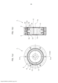
[0047] A Figura 1 é uma vista de superfície de extremidade e uma vista em corte transversal longitudinal de uma engrenagem com onda de tensão de tipo duplo à qual a presente invenção é aplicada;[0047] Figure 1 is an end surface view and a longitudinal cross-sectional view of a dual-type stress wave gear to which the present invention is applied;
[0048] A Figura 2 é um diagrama esquemático da engrenagem com onda de tensão de tipo duplo mostrada na Figura 1;[0048] Figure 2 is a schematic diagram of the dual-type voltage wave gear shown in Figure 1;
[0049] A Figura 3 é uma vista em corte transversal parcial ampliada da engrenagem com onda de tensão mostrada na Figura 1;[0049] Figure 3 is an enlarged partial cross-sectional view of the voltage wave gear shown in Figure 1;
[0050] A Figura 4 é um diagrama que mostra o estado flexionado da engrenagem externamente dentada mostrada na Figura 1; e[0050] Figure 4 is a diagram showing the flexed state of the externally toothed gear shown in Figure 1; It is
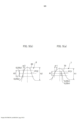
[0051] A Figura 5 é um par de gráficos que mostra o perfil de dentes dos primeiros e dos segundos dentes externos da engrenagem externamente dentada mostrada na Figura 1.[0051] Figure 5 is a pair of graphs showing the tooth profile of the first and second external teeth of the externally toothed gear shown in Figure 1.
[0052] Uma modalidade de uma engrenagem com onda de tensão de tipo duplo à qual a presente invenção é aplicada é descrita abaixo em referência aos desenhos anexos.[0052] One embodiment of a dual type stress wave gear to which the present invention is applied is described below with reference to the accompanying drawings.
[0053] A Figura 1 é uma vista de superfície de extremidade e uma vista em corte transversal longitudinal que mostra uma engrenagem com onda de tensão de tipo duplo (chamada abaixo simplesmente de "engrenagem com onda de tensão") de acordo com uma modalidade da presente invenção, e a Figura 2 é um diagrama esquemático da mesma. A engrenagem com onda de tensão 1, que é usada como, por exemplo, um redutor de engrenagem, tem uma primeira engrenagem internamente dentada rígida anular 2, uma segunda engrenagem internamente dentada rígida anular 3, uma engrenagem internamente dentada flexível cilíndrica 4 que compreende um corpo elástico de parede fina radialmente flexível e um gerador de onda com contorno de elipse 5.[0053] Figure 1 is an end surface view and a longitudinal cross-sectional view showing a dual-type stress wave gear (referred to below simply as a "stress wave gear") according to an embodiment of the present invention, and Figure 2 is a schematic diagram thereof. The
[0054] A primeira e a segunda engrenagens internamente dentadas 2, 3 são dispostas com a finalidade de serem coaxialmente alinhadas em paralelo entre si, com um vão previsto entre as mesmas, ao longo da direção de um eixo geométrico central 1a. No presente exemplo, a primeira engrenagem internamente dentada 2 é uma engrenagem internamente dentada de lado estacionário presa com a finalidade de girar, o número de primeiros dentes internos 2a da mesma é indicado por Zc1. A segunda engrenagem internamente dentada 3 é uma engrenagem internamente dentada de lado de acionamento sustentada de modo girável, o número de segundos dentes internos 3a da mesma é indicado por Zc2. A segunda engrenagem internamente dentada 3 é o elemento de emissão de rotação reduzida da engrenagem com onda de tensão 1.[0054] The first and second internally
[0055] A engrenagem externamente dentada cilíndrica 4 é disposta coaxialmente dentro da primeira e da segunda engrenagens internamente dentadas 2, 3. A engrenagem externamente dentada 4 tem um corpo cilíndrico 6 que é um corpo elástico de parede fina radialmente flexível, primeiros dentes externos 7 e segundos dentes externos 8 formados na superfície periférica externa circular do corpo cilíndrico 6, e um vão 9 (em referência à Figura 3) formado entre os dentes externos 7, 8 em cada lado, em que o vão 9 funciona como uma área de folga de cortador. Os primeiros dentes externos 7 são formados em um lado ao longo da direção do eixo geométrico central 1a da superfície periférica externa circular do corpo cilíndrico 6, e os segundos dentes externos 8 são formados no outro lado de segundo dentes internos 3a da superfície periférica externa circular. Os primeiros e os segundos dentes externos 7, 8 são formados de modo que a direção do eixo geométrico central 1a seja a direção de traço de dente.[0055] The cylindrical externally
[0056] Especificamente, os primeiros dentes externos 7 são formados no lado oposto aos primeiros dentes internos 2a, e têm capacidade de entrelaçar com os primeiros dentes internos 2a, o número de primeiros dentes externos 7 é indicado por Zf1. Os segundos dentes externos 8 são formados no lado oposto aos segundos dentes internos 3a, e têm capacidade de entrelaçar com os segundos dentes internos 3a, o número de segundos dentes externos 8 é indicado por Zf2. Os números Zf1, Zf2 de dentes são diferentes uns dos outros.[0056] Specifically, the first
[0057] O gerador de onda 5 tem um plugue rígido com formato de elipse 11, e um primeiro mancal de onda 12 e segundo mancal de onda 13, em que o primeiro e o segundo mancais de onda são encaixados na superfície periférica externa em formato de elipse do plugue rígido 11. O primeiro e o segundo mancais de onda 12, 13 são formados a partir de mancais esféricos.[0057] The
[0058] O gerador de onda 5 é inserido na superfície periférica interna do corpo cilíndrico 6 da engrenagem externamente dentada 4, e faz com que o corpo cilíndrico 6 se flexione em um formato de elipse. Portanto, os primeiros e os segundos dentes externos 7, 8 são também flexionados em um formato de elipse. A engrenagem externamente dentada flexionada em formato de elipse 4 entrelaça com a primeira e a segunda engrenagens internamente dentadas 2, 3 em ambas as posições de extremidade ao longo do eixo geométrico principal Lmax do formato de elipse. Especificamente, os primeiros dentes externos 7 se entrelaçam com os primeiros dentes internos 2a em ambas as posições de extremidade ao longo do eixo geométrico principal do formato de elipse, e os segundos dentes externos 8 se entrelaçam com os segundos dentes internos 3a em ambas as posições de extremidade ao longo do eixo geométrico principal.[0058] The
[0059] O gerador de onda 5 é o elemento de inserção de rotação da engrenagem com onda de tensão 1. O plugue rígido 11 do gerador de onda 5 tem um orifício de eixo 11c, no qual um eixo de rotação de entrada 10 (em referência à Figura 2) é conectado seguramente em uma disposição coaxial. Por exemplo, um eixo de saída de motor pode ser seguramente conectado em uma disposição coaxial no orifício de eixo 11c. Quando o gerador de onda 5 gira, as posições nas quais os primeiros dentes externos 7 da engrenagem externamente dentada 4 e os primeiros dentes internos de lado estacionário 2a se entrelaçam, e as posições nas quais os segundos dentes externos 8 da engrenagem externamente dentada 4 e os segundos dentes internos de lado de acionamento 3a se entrelaçam, se movem ao longo da direção circunferencial.[0059] The
[0060] O número Zf1 de primeiros dentes externos 7 e o número Zf2 de segundos dentes externos 8 diferem um do outro; no presente exemplo, o número Zf2 de segundos dentes externos é maior. O número Zc1 de primeiros dentes internos 2a e o número Zf1 de primeiros dentes externos 7 também diferem um do outro; no presente exemplo, o número Zc1 de primeiros dentes internos 2a é maior. O número Zc2 de segundos dentes internos 3a e o número Zf2 de segundos dentes externos 8 diferem um do outro; no presente exemplo, o número Zc2 de segundos dentes internos 3a é menor.[0060] The Zf1 number of first
[0061] No presente exemplo, a engrenagem externamente dentada 4 é provocada a flexionar em um formato de elipse, e entrelaça com as engrenagens internamente dentadas 2 e 3 em dois locais ao longo da direção circunferencial. Portanto, a diferença entre o número Zc1 de primeiros dentes internos 2a e o número Zf1 de primeiros dentes externos 7 é 2n1, em que n1 é um número inteiro positivo. A diferença entre o número Zc2 de segundos dentes internos 3a e o número Zf2 de segundos dentes externos 8 é 2n2, em que n2 é um número inteiro positivo. Zc1=Zf1+2n1 Zc2=Zf2-2n2[0061] In the present example, the externally
[0062] Em um exemplo específico, os números de dentes são definidos da seguinte forma (n1=n2=1): Zc1=62 Zf1=60 Zc2=62 Zf2=64[0062] In a specific example, the numbers of teeth are defined as follows (n1=n2=1): Zc1=62 Zf1=60 Zc2=62 Zf2=64
[0063] A razão de velocidade R1 entre a primeira engrenagem internamente dentada 2 e os primeiros dentes externos 7, e a razão de velocidade R2 entre a segunda engrenagem internamente dentada 3 e os segundos dentes externos 8, são respectivamente definidas da seguinte forma: i1=1/R1=(Zf1 -Zcl )/Zf1 =(60—62)/60=-1 /30 i2= 1 /R2=(Zf2-Zc2)/Zf2=(64-62)/64=1 /32[0063] The speed ratio R1 between the first internally
[0064] Portanto, R1=-30 e R2=32.[0064] Therefore, R1=-30 and R2=32.
[0065] A razão de velocidade R da engrenagem com onda de tensão 1 é representada pela seguinte fórmula com o uso das razões de velocidade R1 e R2. Dessa forma, de acordo com a presente invenção, uma engrenagem com onda de tensão que tem uma razão de velocidade dramaticamente baixa (razão de redução baixa) pode ser realizada (uma razão de velocidade negativa indica que a rotação de saída progride na direção oposta à da rotação de entrada). R=(R1xR2-R1)/(-R1+R2) =(-30x32+30)/(30+32) = -930/62 = -15[0065] The gear speed ratio R with
[0066] Dessa forma, de acordo com a engrenagem com onda de tensão 1 do presente exemplo, é possível obter uma razão de velocidade menor que 50, por exemplo, uma razão de velocidade notavelmente menor que 30. Adicionalmente, diferentemente da técnica anterior, os primeiros dentes externos 7 e os segundos dentes externos 8 que diferem em número e módulo são formados como os dentes externos da engrenagem externamente dentada. Consequentemente, há um grau de liberdade maior no projeto para definir a razão de velocidade, e uma engrenagem com onda de tensão que tem uma razão de velocidade baixa pode ser realizada mais facilmente do que na técnica anterior.[0066] Thus, according to the
[0067] A Figura 3 é uma vista em corte transversal parcial ampliada da engrenagem com onda de tensão 1 mostrada na Figura 1. Os primeiros e os segundos dentes externos 7, 8 formados na engrenagem externamente dentada 4 serão agora descritos em detalhes em referência principalmente à Figura 3. No presente exemplo, a largura de dente dos primeiros e dos segundos dentes externos 7, 8 é substancialmente igual à dos primeiros e dos segundos dentes internos 2a, 3a, com a qual os primeiros e os segundo dentes externos 7, 8 têm capacidade de se entrelaçar. Portanto, os primeiros dentes externos 7 e os segundos dentes externos 8, que têm a mesma largura de dente, são formados simetricamente em torno de uma posição central de direção de traço de dente 6a no corpo cilíndrico 6. Em casos em que os primeiros dentes internos 2a e os segundos dentes internos 3a diferem em termos de largura de dente, os primeiros dentes externos 7 e os segundos dentes externos 8 são também configurados com larguras de dente diferentes de uma maneira correspondente.[0067] Figure 3 is an enlarged partial cross-sectional view of the
[0068] O vão 9, que tem uma largura prescrita ao longo da direção de traço de dente, é formado entre os primeiros e os segundos dentes externos 7, 8. O vão 9 funciona como uma área de folga de cortador para cortadores de corte de dente usados para cortar os primeiros e segundos dentes externos 7, 8.[0068]
[0069] A espessura de parede de aro do aro de fundo de dente dos primeiros dentes externos 7 e dos segundos dentes externos 8 é definida da seguinte forma. A segunda espessura de parede de aro t(2) dos segundos dentes externos 8, os quais existem em grandes números, é definida com a finalidade de ser maior que a primeira espessura de parede de aro t(1) dos primeiros dentes externos 7, os quais estão em um número menor, onde a primeira espessura de parede de aro t(1) é a espessura de parede de aro dos primeiros dentes externos 7, e a segunda espessura de parede de aro t(2) é a espessura de parede de aro dos segundos dentes externos 8.
[0070] Os primeiros e segundos dentes externos 7, 8 da engrenagem externamente dentada 4 no presente exemplo são ambos provocados a flexionar em um formato de elipse pelo gerador de onda 5 que tem as duas fileiras de mancais de onda 12, 13. m1 é o módulo dos primeiros dentes externos 7, e m2 é o módulo dos segundos dentes externos 8. 2n1 é a diferença em número entre os primeiros dentes externos 7 e os primeiros dentes internos 2a, e 2n2 é a diferença em número entre os segundos dentes externos 8 e os segundos dentes internos 3a. Portanto, o valor teórico d1 da quantidade pela qual os primeiros dentes externos 7 são radialmente flexionados em posições de eixo geométrico principal Lmax e o valor teórico d2 da quantidade pela qual os segundos dentes externos 8 são radialmente flexionados quando os dentes externos são flexionados em um formato de elipse são respectivamente representados pelo seguinte.
[0071] No caso dos primeiros e segundos dentes externos 7, 8 que diferem em número e são formados na superfície periférica externa do mesmo corpo cilíndrico 6, os diâmetros de círculo de intervalo dos dentes em ambos os lados são aproximadamente iguais. Consequentemente, o valor teórico mn da quantidade de flexão radial é normalmente menor quando o número de dentes é maior.[0071] In the case of the first and second
[0072] No presente exemplo, as quantidades pelas quais os primeiros e os segundos dentes externos 7, 8 são radialmente flexionados pelo gerador de onda 5 são ambas definidas como quantidade d. A quantidade d de flexão radial é representada pelo seguinte
[0073] A Figura 4 é um diagrama que mostra o estado flexionado da engrenagem externamente dentada 4. Na Figura 4, o círculo neutro de aro C é o círculo que atravessa o centro de espessura do corpo cilíndrico (aro de fundo de dente) 6 em um estado no qual a engrenagem externamente dentada 4 é perfeitamente circular antes de ser flexionada em um formato de elipse. O círculo neutro de aro C é deformado em um formato de elipse devido à engrenagem externamente dentada 4 que é flexionada em um formato de elipse. Esse círculo deformado é chamado de curva neutra de aro em formato de elipse C1.[0073] Figure 4 is a diagram showing the flexed state of the externally
[0074] A quantidade d pela qual a engrenagem externamente dentada 4 é radialmente flexionada é a diferença entre o raio do eixo geométrico principal Lmax da curva neutra de aro em formato de elipse C1 e o raio do círculo neutro de aro C. Essa quantidade d é representada por Kmn, onde m é o módulo da engrenagem externamente dentada, 2n é a diferença em número de dentes em relação às engrenagens internamente dentadas (n sendo um número inteiro positivo), e K é o coeficiente de deflexão. A quantidade mn de flexão radial quando K é igual a 1 é um valor obtido pela divisão do diâmetro de círculo de arfagem da engrenagem externamente dentada pela razão de redução de quando a engrenagem internamente dentada rígida é presa; esse é o valor teórico (quantidade de flexão em uma deflexão padrão) da quantidade de flexão radial.[0074] The amount d by which the externally
[0075] No presente exemplo, o estado de flexão dos primeiros dentes externos 7, os quais estão em um número menor, é definido como uma quantidade de flexão menor que o valor teórico (uma quantidade de flexão em um ângulo de deflexão negativo onde k < 1), conforme descrito acima. Adversamente, o estado de flexão dos segundos dentes externos 8, os quais estão em um número maior, é definido como uma quantidade de flexão maior que o valor teórico (uma quantidade de flexão em um ângulo de deflexão positivo onde k>1).[0075] In the present example, the state of flexion of the first
[0076] A Figura 5(a) é um gráfico que mostra o ângulo de pressão do perfil de dente que define os primeiros dentes externos 7, e a Figura 5(b) é um gráfico que mostra o ângulo de pressão do perfil de dente que define os segundos dentes externos 8. Os ângulos de pressão dos perfis de dente dos primeiros e dos segundos dentes externos 7 e 8 no presente exemplo são descritos em referência a esses gráficos.[0076] Figure 5(a) is a graph showing the pressure angle of the tooth profile that defines the first
[0077] Na Figura 5(a), que mostra um perfil de dente 70 dos primeiros dentes externos 7, uma região de área de contato de dente principal A1 é a região de área de contato de dente que define uma faixa de 50% do total de profundidade de dente h1 do perfil de dente 70, em que a região de área de contato de dente principal A1 é centralizada em torno do círculo de intervalo PC1. A média dos ângulos que são formados por uma linha central de perfil de dente do perfil de dente 70 e uma linha tangente de perfil de dente que se estende para porções individuais da região de área de contato de dente principal A1 é determinada, em que essa média é um primeiro ângulo de pressão médio α1.[0077] In Figure 5(a), which shows a
[0078] De modo similar, na Figura 5(b), que mostra um perfil de dente 80 dos segundos dentes externos 8, uma região de área de contato de dente principal A2 é a região de área de contato de dente que define uma faixa de 50% do total de profundidade de dente h2 do perfil de dente 80, em que a região de área de contato de dente principal A2 é centralizada em torno do círculo de intervalo PC2. A média de ângulos que são formados por uma linha central de perfil de dente do perfil de dente 80 e uma linha tangente de perfil de dente que se estende para porções individuais da região de área de contato de dente principal A2 é determinada, em que essa média é um segundo ângulo de pressão médio α2.[0078] Similarly, in Figure 5(b), which shows a
[0079] No presente exemplo, o primeiro ângulo de pressão médio α1 dos primeiros dentes externos 7, os quais estão em um número menor, é definida com a finalidade de ser maior que o segundo ângulo de pressão médio α2 dos segundos dentes externos 8, os quais estão em um maior número (isto é, α1>α2). Por exemplo, a relação entre o primeiro e o segundo ângulos de pressão médios α1, α2 pode ser estabelecida da seguinte forma.
[0080] De acordo com os experimentos executados pelos inventores, foi confirmado que a relação entre o primeiro e o segundo ângulos de pressão médios α1, α2 é de preferência estabelecida da seguinte forma.
[0081] Ao definir os ângulos de pressão médios dos primeiros e dos segundos dentes externos 7 e 8 que diferem em número conforme descrito acima, tanto os primeiros quanto os segundos dentes externos 7 e 8 podem ser entrelaçados de uma maneira satisfatória com as engrenagens internamente dentadas correspondentes. Além disso, foi confirmado que a resistência a desgaste dos primeiros e dos segundos dentes externos 7 e 8 é aprimorada, e que o equilíbrio da resistência à fadiga de fundo de dentes entre os primeiros e os segundos dentes externos 7 e 8 é aprimorada. Também foi confirmado que a distribuição de carga de esfera de mancal das duas fileiras dos mancais de onda 12 e 13 do gerador de onda 5 para sustentar os primeiros e os segundos dentes externos 7 e 8 pode ser uniforme e que os tempos de vida dos mancais de onda 12 e 13 pode ser prolongado.[0081] By defining the average pressure angles of the first and second
[0082] O vão 9 formado entre os primeiros e os segundos dentes externos 7, 8 é descrito a seguir em referência à Figura 3. Conforme descrito anteriormente, o vão 9 funciona como uma área de folga de cortador para cortadores de corte de dente usados para cortar os primeiros e segundos dentes externos 7, 8.[0082] The
[0083] O vão 9 tem uma largura prescrita ao longo da direção de traço de dente; a parte mais profunda, que é a parte do vão 9 que é formada mais profundamente ao longo da direção de profundidade de dente, é formada na porção central de direção de traço de dente. No presente exemplo, a parte mais profunda 9a é uma porção na qual a porção central de direção de traço de dente é definida por uma linha reta que se estende paralela à direção de traço de dente, conforme visualizado a partir da direção de espessura de dente. Nas duas extremidades de direção de traço de dente da parte mais profunda 9a, uma curva arqueada côncava que define a superfície de extremidade interna de direção de traço de dente 7a dos primeiros dentes externos 7 e uma curva arqueada côncava que define a superfície de extremidade interna de direção de traço de dente 8a dos segundos dentes externos 8 são suavemente conectadas. Também é possível adotar uma configuração na qual a parte mais profunda 9a é definida por uma superfície curva côncava e as duas superfícies de extremidade interna 7a, 8a são definidas por linhas retas inclinadas. É adicionalmente possível adotar uma configuração na qual a parte mais profunda 9a é definida por uma linha reta e as duas superfícies de extremidade interna 7a, 8a são definidas por linhas retas inclinadas.[0083]
[0084] A direção de traço de dente largura do vão 9 no presente exemplo aumenta gradualmente a partir da parte mais profunda 9a ao longo da direção de profundidade de dente. A largura máxima L1 na direção de traço de dente é a distância, ao longo da direção de traço de dente, a partir da extremidade interna de direção de traço de dente 7b do círculo adendo dos primeiros dentes externos 7 para a extremidade interna de direção de traço de dente 8b do círculo adendo dos segundos dentes externos 8.[0084] The tooth trace
[0085] A relação
[0086] é estabelecida, em que L é a largura a partir da extremidade externa de direção de traço de dente 7c dos primeiros dentes externos 7 para a extremidade externa de direção de traço de dente 8c dos segundos dentes externos 8, e L1 é a largura máxima de direção de traço de dente do vão 9.[0086] is established, where L is the width from the outer end of
[0087] A profundidade da parte mais profunda 9a do vão 9 é definida da seguinte forma. As relações
[0088] são estabelecidas, em que h1 é a profundidade de dente dos primeiros dentes externos 7, h2 é a profundidade de dente dos segundos dentes externos 8, t1 é a profundidade de direção de profundidade de dente da área de contato de topo 7d dos primeiros dentes externos 7 até a parte mais profunda 9a, e t2 é a profundidade de direção de profundidade de dente da área de contato de topo 8d dos segundos dentes externos 8 até a parte mais profunda 9a.[0088] are established, where h1 is the tooth depth of the first
[0089] Na engrenagem externamente dentada 4 da engrenagem com onda de tensão do tipo duplo 1, os cortadores de corte de dente usados para cortar os primeiros e os segundos dentes externos 7, 8 são também diferentes entre si. Portanto, o vão 9, que funciona como uma área de folga de corte, é formado na porção central de direção de traço de dente da engrenagem externamente dentada 4; isto é, entre os primeiros dentes externos 7 e os segundos dentes externos 8.[0089] In the externally
[0090] A maneira na qual o vão 9 é formado tem um efeito proeminente sobre o contato de dente dos primeiros dentes externos 7 em relação aos primeiros dentes internos 2a ao longo da direção de traço de dente, bem como sobre a distribuição de carga de área de contato de dente. A maneira na qual o vão 9 é formado tem de modo similar um efeito proeminente sobre o contato de dente dos segundos dentes externos 8 em relação aos segundos dentes internos 3a ao longo da direção de traço de dente, bem como sobre a distribuição de carga de área de contato de dente.[0090] The way in which the
[0091] Em vista desses pontos, a largura máxima L1 do vão é definida dentro de uma faixa de 0,1 a 0,3 vezes a largura L da engrenagem externamente dentada, e as profundidades máximas t1, t2 são definidas dentro de uma faixa de 0,9 a 1,3 vezes as profundidades de dente h1, h2 dos primeiros e segundos dentes externos 7, 8 conforme descrito acima. Foi confirmado que a formação do vão 9 dessa maneira torna possível manter a uniformidade nas distribuições de carga de área de contato de dente de direção de traço de dente dos primeiros e segundos dentes externos 7, 8 para manter um estado satisfatório para o contato de dente dos primeiros e dos segundos dentes externos 7, 8 em relação aos primeiros e aos segundos dentes internos 2a, 3a em cada posição de direção de traço de dente.[0091] In view of these points, the maximum span width L1 is defined within a range of 0.1 to 0.3 times the width L of the externally toothed gear, and the maximum depths t1, t2 are defined within a range from 0.9 to 1.3 times the tooth depths h1, h2 of the first and second
[0092] A distância entre os centros de esfera de mancal do primeiro e do segundo mancais de onda 12, 13 é descrita a seguir em referência à Figura 3.[0092] The distance between the bearing ball centers of the first and
[0093] No plugue rígido 11 do gerador de onda 5, uma primeira superfície periférica externa com contorno de elipse 11a de largura fixa é formada em um lado da direção de eixo geométrico central, e uma segunda superfície periférica externa com contorno de elipse 11b de largura fixa é formada no outro lado da direção de eixo geométrico central. A primeira superfície periférica externa 11a e a segunda superfície periférica externa 11b são superfícies periféricas externas em formato de elipse que têm o mesmo formato e a mesma fase.[0093] On the
[0094] O primeiro mancal de onda 12 é encaixado na primeira superfície periférica externa 11a em um estado que é flexionado em um formato de elipse, e o segundo mancal de onda 13 é encaixado na segunda superfície periférica externa 11b em um estado que é flexionado em um formato de elipse. O primeiro e o segundo mancais de onda 12, 13 são do mesmo tamanho.[0094] The first wave bearing 12 is fitted to the first outer
[0095] Os centros de mancal 12a, 13a do primeiro mancal de onda 12 e do segundo mancal de onda 13 estão localizados em posições que são equidistantes, ao longo da direção de largura de dente, a partir da posição central de direção de traço de dente 6a na engrenagem externamente dentada 4. A distância entre centros de esfera de mancal é definida com a finalidade de aumentar correspondentemente com um aumento na largura máxima L1 do vão 9. Adicionalmente, a distância de centro entre esferas Lo é definida com a finalidade de alcançar um valor dentro da faixa indicado pela seguinte fórmula, Lo sendo a distância entre centros de esfera de mancal.
[0096] Na técnica anterior, um gerador de onda que tem duas fileiras de mancais esféricos é usado a fim de aumentar a área na qual a engrenagem externamente dentada é sustentada. As duas fileiras de mancais de esfera foram dispostas em relação à porção central de direção de largura de dente da engrenagem externamente dentada, independentemente da distância de centro entre esferas.[0096] In the prior art, a wave generator having two rows of spherical bearings is used in order to increase the area on which the externally toothed gear is supported. The two rows of ball bearings were arranged relative to the tooth-width drive center portion of the externally toothed gear, regardless of the center distance between balls.
[0097] No presente exemplo, a distância de centro entre esferas Lo entre duas fileiras de mancais de onda 12, 13 é aumentada de modo que seja possível aumentar a rigidez para sustentar os primeiros e os segundos dentes externos 7, 8 que diferem em número, e para aprimorar o contato de dente de cada um dos dentes externos 7, 8 em relação aos dentes internos 2a em cada posição de direção de traço de dente. Especificamente, conforme descrito acima, é adotada uma configuração na qual a distância de centro entre esferas Lo se estende (aumenta) em correspondência com um aumento no comprimento máximo de direção de traço de dente L1 do vão 9, que é formado entre os primeiros e os segundos dentes externos 7,8 e funciona como uma área de folga de cortador. A faixa de aumento da distância de centro entre esferas Lo é definida como 0,35 a 0,7 vezes a largura L da engrenagem externamente dentada 4.[0097] In the present example, the ball center distance Lo between two rows of
[0098] Isso torna possível dispor o primeiro e o segundo mancais de onda 12, 13 de modo que os centos da esfera sejam posicionados nas posições de direção de traço de dente adequadas em relação a cada um dos primeiros e segundos dentes externos 7, 8 de acordo com a largura do vão que é formado. Isso torna possível sustentar confiavelmente os primeiros e os segundos dentes externos 7, 8, com o uso do primeiro e do segundo mancais de onda 12, 13, em cada posição de direção de traço de dente de cada um dos primeiros e segundos dentes externos 7, 8 (isto é, para aumentar a rigidez de sustentação do gerador de onda 5).[0098] This makes it possible to arrange the first and
[0099] Como um resultado, é possível aprimorar o contato de dente dos primeiros e segundos dentes externos 7, 8 em cada posição de direção de traço de dente, e aumentar a resistência à fadiga de fundo de dente dos mesmos. Também é possível ponderar a distribuição de carga de esfera de mancal de cada um dos mancais de onda 12, 13 do gerador de onda 5, e reduzir a carga máxima; portanto, a vida útil do gerador de onda 5 pode ser aprimorada.[0099] As a result, it is possible to improve the tooth contact of the first and second
[00100] No exemplo descrito acima, a primeira engrenagem internamente dentada 2 é configurada como uma engrenagem internamente dentada de lado estacionário, e a segunda engrenagem internamente dentada 3 é configurada como uma engrenagem internamente dentada de lado de acionamento (membro de emissão de rotação reduzida). Entretanto, é possível, em vez disso, configurar a primeira engrenagem internamente dentada 2 como uma engrenagem internamente dentada de lado de acionamento (membro de emissão de rotação reduzida), e configurar a segunda engrenagem internamente dentada 3 como uma engrenagem internamente dentada de lado estacionário.[00100] In the example described above, the first internally
Claims (9)


Applications Claiming Priority (3)
| Application Number | Priority Date | Filing Date | Title |
|---|---|---|---|
| JP2014149374A JP6218692B2 (en) | 2014-07-23 | 2014-07-23 | Dual type wave gear device |
| JP2014-149374 | 2014-07-23 | ||
| PCT/JP2015/069246 WO2016013382A1 (en) | 2014-07-23 | 2015-07-03 | Dual-type wave gear device |
Publications (2)
| Publication Number | Publication Date |
|---|---|
| BR112017000374A2 BR112017000374A2 (en) | 2018-03-27 |
| BR112017000374B1 true BR112017000374B1 (en) | 2023-02-14 |
Family
ID=55162914
Family Applications (1)
| Application Number | Title | Priority Date | Filing Date |
|---|---|---|---|
| BR112017000374-0A BR112017000374B1 (en) | 2014-07-23 | 2015-07-03 | DUAL TYPE TENSION WAVE GEAR |
Country Status (10)
| Country | Link |
|---|---|
| US (1) | US10197145B2 (en) |
| EP (1) | EP3173658B1 (en) |
| JP (1) | JP6218692B2 (en) |
| KR (1) | KR101838926B1 (en) |
| CN (1) | CN106536975B (en) |
| BR (1) | BR112017000374B1 (en) |
| MX (1) | MX2017001003A (en) |
| RU (1) | RU2655578C1 (en) |
| TW (1) | TWI620883B (en) |
| WO (1) | WO2016013382A1 (en) |
Families Citing this family (8)
| Publication number | Priority date | Publication date | Assignee | Title |
|---|---|---|---|---|
| JP6370624B2 (en) * | 2014-07-23 | 2018-08-08 | 株式会社ハーモニック・ドライブ・システムズ | Dual type wave gear device |
| CN106641183B (en) * | 2016-12-28 | 2019-01-29 | 重庆奔腾智能装备技术有限公司 | Harmonic drive rack gear approximation tooth Profile Design method |
| US10253864B2 (en) * | 2017-07-03 | 2019-04-09 | Optimal Actuation Inc. | Bearing wave generator assembly |
| DE102017119323A1 (en) | 2017-08-24 | 2018-09-06 | Schaeffler Technologies AG & Co. KG | Gear pairing and wave gear |
| JP6552571B2 (en) * | 2017-09-29 | 2019-07-31 | 株式会社ハーモニック・ドライブ・システムズ | Dual type wave gear device |
| US11092224B2 (en) | 2017-10-10 | 2021-08-17 | Hamilton Sundstrand Corporation | Method of developing spline profile |
| CN108730478B (en) * | 2018-08-14 | 2021-06-15 | 台邦电机工业集团有限公司 | Harmonic gear |
| CN110671482A (en) * | 2019-10-11 | 2020-01-10 | 重庆大学 | Double wave complex wave type oscillating tooth speed reducer |
Family Cites Families (30)
| Publication number | Priority date | Publication date | Assignee | Title |
|---|---|---|---|---|
| SU1137269A1 (en) * | 1980-06-30 | 1985-01-30 | МВТУ им.Н.Э.Баумана | Twin wave gearing |
| US4601216A (en) * | 1982-06-18 | 1986-07-22 | Matsushita Electric Industrial Co., Ltd. | Reduction gear |
| JP2503027B2 (en) | 1987-09-21 | 1996-06-05 | 株式会社ハーモニック・ドライブ・システムズ | Flexible mesh gear |
| JPS6491151A (en) | 1987-10-02 | 1989-04-10 | Ricoh Kk | Device for operating copying machine |
| JPH01108441A (en) * | 1987-10-20 | 1989-04-25 | Sumitomo Heavy Ind Ltd | Differential gear mechanism |
| JPH0451235Y2 (en) | 1987-12-10 | 1992-12-02 | ||
| JP2718540B2 (en) | 1989-04-17 | 1998-02-25 | 株式会社ハーモニック・ドライブ・システムズ | Wave gear device |
| JP3739017B2 (en) * | 1995-12-15 | 2006-01-25 | 株式会社ハーモニック・ドライブ・システムズ | Flexible meshing gear system with non-interfering wide meshing teeth |
| UA78075C2 (en) * | 2005-02-07 | 2007-02-15 | Robert Vachahan Ambartsumiants | Method for determination of teeth module of involute cylindrical toothed wheels |
| JPWO2007116756A1 (en) * | 2006-03-31 | 2009-08-20 | 株式会社ジェイテクト | Flexure meshing gear device and vehicle steering device |
| JP4999475B2 (en) | 2007-01-24 | 2012-08-15 | 株式会社ハーモニック・ドライブ・システムズ | Flat wave gear device |
| US8028603B2 (en) * | 2007-12-04 | 2011-10-04 | Harmonic Drive Systems Inc. | Method for setting gear tooth profile in flat wave gear device on side where gears have same number of teeth |
| JP4877837B2 (en) * | 2007-12-04 | 2012-02-15 | 株式会社ハーモニック・ドライブ・システムズ | Tooth profile setting method for the same number of teeth side gear of flat type wave gear device |
| KR100988215B1 (en) * | 2008-06-24 | 2010-10-18 | 한국과학기술연구원 | Harmonic drive using profile shifted gear |
| JP5337008B2 (en) | 2009-11-30 | 2013-11-06 | 住友重機械工業株式会社 | Flexure meshing gear device and method of manufacturing the external gear |
| CN102753859B (en) * | 2010-02-15 | 2015-03-11 | 株式会社捷太格特 | Swing internal contact type planetary gear device and rotation drive device |
| JP5256249B2 (en) * | 2010-06-18 | 2013-08-07 | 住友重機械工業株式会社 | Bending gear system |
| JP5734102B2 (en) * | 2011-06-01 | 2015-06-10 | 株式会社ハーモニック・ドライブ・システムズ | Wave gear device having a tapered flexible external gear |
| WO2013038463A1 (en) * | 2011-09-16 | 2013-03-21 | 株式会社ハーモニック・ドライブ・システムズ | Vibration power-generating strain wave gearing |
| WO2013046274A1 (en) * | 2011-09-29 | 2013-04-04 | 株式会社ハーモニック・ドライブ・システムズ | Wave gear device having tapered flexible external gear |
| JP5639992B2 (en) * | 2011-12-08 | 2014-12-10 | 住友重機械工業株式会社 | Bending gear system |
| JP5833480B2 (en) * | 2012-03-21 | 2015-12-16 | 本田技研工業株式会社 | Wave gear device and walking assist device |
| JP5496416B1 (en) * | 2012-05-31 | 2014-05-21 | 株式会社ハーモニック・ドライブ・システムズ | Wave gear device and flexible internal gear |
| JPWO2015001974A1 (en) * | 2013-07-01 | 2017-02-23 | 株式会社ハーモニック・ドライブ・システムズ | Wave gear device |
| US9341252B2 (en) * | 2013-07-10 | 2016-05-17 | Harmonic Drive Systems Inc. | Wave generator and strain wave gearing |
| DE112013006221T5 (en) * | 2013-11-19 | 2015-09-24 | Harmonic Drive Systems Inc. | Deformation wave gear, wave device with friction engagement and wave generator |
| KR101763719B1 (en) * | 2014-03-31 | 2017-08-01 | 가부시키가이샤 하모닉 드라이브 시스템즈 | Wave gear device and method for manufacturing multi-layered hollow body |
| EP3141777A4 (en) * | 2014-05-08 | 2018-03-21 | Harmonic Drive Systems Inc. | Wave generator for wave gear device and production method for wave generator |
| WO2016006102A1 (en) * | 2014-07-11 | 2016-01-14 | 株式会社ハーモニック・ドライブ・システムズ | Strain wave gear device comprising continuous contact tooth profile formed using circular arc tooth profile |
| JP6751230B2 (en) * | 2016-06-27 | 2020-09-02 | サミー株式会社 | Amusement machine |
-
2014
- 2014-07-23 JP JP2014149374A patent/JP6218692B2/en active Active
-
2015
- 2015-07-03 MX MX2017001003A patent/MX2017001003A/en active IP Right Grant
- 2015-07-03 BR BR112017000374-0A patent/BR112017000374B1/en active IP Right Grant
- 2015-07-03 US US15/327,750 patent/US10197145B2/en active Active
- 2015-07-03 RU RU2016148942A patent/RU2655578C1/en active
- 2015-07-03 WO PCT/JP2015/069246 patent/WO2016013382A1/en active Application Filing
- 2015-07-03 CN CN201580038727.1A patent/CN106536975B/en active Active
- 2015-07-03 EP EP15824078.8A patent/EP3173658B1/en active Active
- 2015-07-03 KR KR1020167036440A patent/KR101838926B1/en active IP Right Grant
- 2015-07-20 TW TW104123407A patent/TWI620883B/en active
Also Published As
| Publication number | Publication date |
|---|---|
| RU2655578C1 (en) | 2018-05-28 |
| CN106536975A (en) | 2017-03-22 |
| JP6218692B2 (en) | 2017-10-25 |
| EP3173658A1 (en) | 2017-05-31 |
| EP3173658A4 (en) | 2018-05-02 |
| KR20170010325A (en) | 2017-01-26 |
| US10197145B2 (en) | 2019-02-05 |
| BR112017000374A2 (en) | 2018-03-27 |
| JP2016023746A (en) | 2016-02-08 |
| EP3173658B1 (en) | 2019-10-16 |
| TWI620883B (en) | 2018-04-11 |
| US20170198802A1 (en) | 2017-07-13 |
| CN106536975B (en) | 2018-12-04 |
| TW201616013A (en) | 2016-05-01 |
| WO2016013382A1 (en) | 2016-01-28 |
| MX2017001003A (en) | 2017-09-01 |
| KR101838926B1 (en) | 2018-03-15 |
Similar Documents
| Publication | Publication Date | Title |
|---|---|---|
| BR112017000374B1 (en) | DUAL TYPE TENSION WAVE GEAR | |
| BR112017000371B1 (en) | DUAL TYPE TENSION WAVE GEAR | |
| BR112017000375B1 (en) | DUAL TYPE TENSION WAVE GEAR | |
| BR112017000368B1 (en) | DUAL TYPE TENSION WAVE GEAR | |
| BR112017000370B1 (en) | DUAL TYPE TENSION WAVE GEAR | |
| BR112017000366B1 (en) | DUAL TYPE TENSION WAVE GEAR | |
| RU2714353C1 (en) | Double-shaft transmission |
Legal Events
| Date | Code | Title | Description |
|---|---|---|---|
| B15I | Others concerning applications: loss of priority | ||
| B12F | Other appeals [chapter 12.6 patent gazette] | ||
| B06U | Preliminary requirement: requests with searches performed by other patent offices: procedure suspended [chapter 6.21 patent gazette] | ||
| B09A | Decision: intention to grant [chapter 9.1 patent gazette] | ||
| B16A | Patent or certificate of addition of invention granted [chapter 16.1 patent gazette] |
Free format text: PRAZO DE VALIDADE: 20 (VINTE) ANOS CONTADOS A PARTIR DE 03/07/2015, OBSERVADAS AS CONDICOES LEGAIS |