US11833676B2 - Combining sensor output data to prevent unsafe operation of an exoskeleton - Google Patents
Combining sensor output data to prevent unsafe operation of an exoskeleton Download PDFInfo
- Publication number
- US11833676B2 US11833676B2 US17/114,457 US202017114457A US11833676B2 US 11833676 B2 US11833676 B2 US 11833676B2 US 202017114457 A US202017114457 A US 202017114457A US 11833676 B2 US11833676 B2 US 11833676B2
- Authority
- US
- United States
- Prior art keywords
- exoskeleton
- joint
- sensor
- output data
- sensors
- Prior art date
- Legal status (The legal status is an assumption and is not a legal conclusion. Google has not performed a legal analysis and makes no representation as to the accuracy of the status listed.)
- Active, expires
Links
- 230000007246 mechanism Effects 0.000 claims abstract description 338
- 230000033001 locomotion Effects 0.000 claims abstract description 129
- 230000002547 anomalous effect Effects 0.000 claims abstract description 93
- 238000000034 method Methods 0.000 claims abstract description 81
- 230000007257 malfunction Effects 0.000 claims abstract description 44
- 230000000246 remedial effect Effects 0.000 claims description 56
- 230000005540 biological transmission Effects 0.000 claims description 48
- 238000001514 detection method Methods 0.000 claims description 25
- 230000004044 response Effects 0.000 claims description 9
- 230000009471 action Effects 0.000 claims description 2
- 230000008859 change Effects 0.000 claims description 2
- 210000002310 elbow joint Anatomy 0.000 description 25
- 230000003190 augmentative effect Effects 0.000 description 24
- 210000003414 extremity Anatomy 0.000 description 20
- 238000012546 transfer Methods 0.000 description 20
- 230000006870 function Effects 0.000 description 19
- 238000004891 communication Methods 0.000 description 16
- 238000010586 diagram Methods 0.000 description 13
- 238000006073 displacement reaction Methods 0.000 description 13
- 238000005516 engineering process Methods 0.000 description 13
- 210000000323 shoulder joint Anatomy 0.000 description 13
- 210000001503 joint Anatomy 0.000 description 12
- 210000000629 knee joint Anatomy 0.000 description 12
- 230000006835 compression Effects 0.000 description 11
- 238000007906 compression Methods 0.000 description 11
- 230000002950 deficient Effects 0.000 description 11
- 210000002414 leg Anatomy 0.000 description 11
- 210000002683 foot Anatomy 0.000 description 10
- 230000015654 memory Effects 0.000 description 10
- 238000012545 processing Methods 0.000 description 9
- 230000005355 Hall effect Effects 0.000 description 8
- 208000027418 Wounds and injury Diseases 0.000 description 8
- 230000006378 damage Effects 0.000 description 8
- 230000005291 magnetic effect Effects 0.000 description 8
- 230000008878 coupling Effects 0.000 description 7
- 238000010168 coupling process Methods 0.000 description 7
- 238000005859 coupling reaction Methods 0.000 description 7
- 208000014674 injury Diseases 0.000 description 7
- 230000008569 process Effects 0.000 description 7
- 230000005484 gravity Effects 0.000 description 6
- 238000005259 measurement Methods 0.000 description 6
- 238000004364 calculation method Methods 0.000 description 5
- 230000005021 gait Effects 0.000 description 5
- 210000003127 knee Anatomy 0.000 description 5
- 230000006855 networking Effects 0.000 description 5
- 238000013016 damping Methods 0.000 description 4
- 230000007547 defect Effects 0.000 description 4
- 230000003287 optical effect Effects 0.000 description 4
- 230000009466 transformation Effects 0.000 description 4
- 210000001624 hip Anatomy 0.000 description 3
- 230000014759 maintenance of location Effects 0.000 description 3
- 230000009467 reduction Effects 0.000 description 3
- 239000011800 void material Substances 0.000 description 3
- 238000003491 array Methods 0.000 description 2
- 230000008901 benefit Effects 0.000 description 2
- 230000000295 complement effect Effects 0.000 description 2
- 238000013500 data storage Methods 0.000 description 2
- 230000005684 electric field Effects 0.000 description 2
- 239000003302 ferromagnetic material Substances 0.000 description 2
- 239000012530 fluid Substances 0.000 description 2
- 210000004247 hand Anatomy 0.000 description 2
- 238000010438 heat treatment Methods 0.000 description 2
- 210000004394 hip joint Anatomy 0.000 description 2
- 238000010348 incorporation Methods 0.000 description 2
- 230000003993 interaction Effects 0.000 description 2
- 238000003032 molecular docking Methods 0.000 description 2
- 238000012544 monitoring process Methods 0.000 description 2
- 230000000737 periodic effect Effects 0.000 description 2
- 230000009897 systematic effect Effects 0.000 description 2
- 238000012384 transportation and delivery Methods 0.000 description 2
- 206010023230 Joint stiffness Diseases 0.000 description 1
- 239000008186 active pharmaceutical agent Substances 0.000 description 1
- 210000003484 anatomy Anatomy 0.000 description 1
- 210000000544 articulatio talocruralis Anatomy 0.000 description 1
- 230000009286 beneficial effect Effects 0.000 description 1
- 230000002902 bimodal effect Effects 0.000 description 1
- 239000006227 byproduct Substances 0.000 description 1
- 230000000981 bystander Effects 0.000 description 1
- 239000003795 chemical substances by application Substances 0.000 description 1
- 238000010276 construction Methods 0.000 description 1
- 238000012937 correction Methods 0.000 description 1
- 125000004122 cyclic group Chemical group 0.000 description 1
- 230000001419 dependent effect Effects 0.000 description 1
- 238000013461 design Methods 0.000 description 1
- 238000007599 discharging Methods 0.000 description 1
- 239000012636 effector Substances 0.000 description 1
- 230000005672 electromagnetic field Effects 0.000 description 1
- 230000007717 exclusion Effects 0.000 description 1
- 230000004907 flux Effects 0.000 description 1
- 239000000446 fuel Substances 0.000 description 1
- 230000003116 impacting effect Effects 0.000 description 1
- 238000012423 maintenance Methods 0.000 description 1
- 238000007726 management method Methods 0.000 description 1
- 238000013507 mapping Methods 0.000 description 1
- 239000011159 matrix material Substances 0.000 description 1
- 238000012986 modification Methods 0.000 description 1
- 230000004048 modification Effects 0.000 description 1
- 238000013021 overheating Methods 0.000 description 1
- 230000000717 retained effect Effects 0.000 description 1
- 239000004065 semiconductor Substances 0.000 description 1
- 239000007787 solid Substances 0.000 description 1
- 230000005236 sound signal Effects 0.000 description 1
- 125000006850 spacer group Chemical group 0.000 description 1
- 238000009987 spinning Methods 0.000 description 1
- 239000013589 supplement Substances 0.000 description 1
- 238000012360 testing method Methods 0.000 description 1
- 230000007723 transport mechanism Effects 0.000 description 1
- 238000013024 troubleshooting Methods 0.000 description 1
- 230000000007 visual effect Effects 0.000 description 1
- 210000003857 wrist joint Anatomy 0.000 description 1
Images


Classifications
-
- B—PERFORMING OPERATIONS; TRANSPORTING
- B25—HAND TOOLS; PORTABLE POWER-DRIVEN TOOLS; MANIPULATORS
- B25J—MANIPULATORS; CHAMBERS PROVIDED WITH MANIPULATION DEVICES
- B25J9/00—Programme-controlled manipulators
- B25J9/0006—Exoskeletons, i.e. resembling a human figure
-
- B—PERFORMING OPERATIONS; TRANSPORTING
- B25—HAND TOOLS; PORTABLE POWER-DRIVEN TOOLS; MANIPULATORS
- B25J—MANIPULATORS; CHAMBERS PROVIDED WITH MANIPULATION DEVICES
- B25J13/00—Controls for manipulators
- B25J13/08—Controls for manipulators by means of sensing devices, e.g. viewing or touching devices
- B25J13/085—Force or torque sensors
-
- B—PERFORMING OPERATIONS; TRANSPORTING
- B25—HAND TOOLS; PORTABLE POWER-DRIVEN TOOLS; MANIPULATORS
- B25J—MANIPULATORS; CHAMBERS PROVIDED WITH MANIPULATION DEVICES
- B25J9/00—Programme-controlled manipulators
- B25J9/16—Programme controls
- B25J9/1628—Programme controls characterised by the control loop
- B25J9/1653—Programme controls characterised by the control loop parameters identification, estimation, stiffness, accuracy, error analysis
-
- B—PERFORMING OPERATIONS; TRANSPORTING
- B25—HAND TOOLS; PORTABLE POWER-DRIVEN TOOLS; MANIPULATORS
- B25J—MANIPULATORS; CHAMBERS PROVIDED WITH MANIPULATION DEVICES
- B25J9/00—Programme-controlled manipulators
- B25J9/16—Programme controls
- B25J9/1674—Programme controls characterised by safety, monitoring, diagnostic
-
- G—PHYSICS
- G05—CONTROLLING; REGULATING
- G05B—CONTROL OR REGULATING SYSTEMS IN GENERAL; FUNCTIONAL ELEMENTS OF SUCH SYSTEMS; MONITORING OR TESTING ARRANGEMENTS FOR SUCH SYSTEMS OR ELEMENTS
- G05B2219/00—Program-control systems
- G05B2219/30—Nc systems
- G05B2219/40—Robotics, robotics mapping to robotics vision
- G05B2219/40204—Each fault condition has a different recovery procedure
-
- G—PHYSICS
- G05—CONTROLLING; REGULATING
- G05B—CONTROL OR REGULATING SYSTEMS IN GENERAL; FUNCTIONAL ELEMENTS OF SUCH SYSTEMS; MONITORING OR TESTING ARRANGEMENTS FOR SUCH SYSTEMS OR ELEMENTS
- G05B2219/00—Program-control systems
- G05B2219/30—Nc systems
- G05B2219/40—Robotics, robotics mapping to robotics vision
- G05B2219/40305—Exoskeleton, human robot interaction, extenders
Definitions
- Robotic systems such as exoskeletons and humanoid robots
- exoskeletons in which there is a human operator donning and operating the exoskeleton
- these can inherently pose a safety risk to the human operator donning the exoskeleton, such as if one or more components or systems of the exoskeleton fails or malfunctions leading to unintended operation scenarios.
- both exoskeletons and humanoid robots these can pose safety risks to others in the vicinity of the operating exoskeleton or humanoid robot as a result of similar failures of malfunctions.
- exoskeletons and other humanoid robots are becoming more and more prevalent in their use as technologies and efficiencies improve.
- exoskeletons full body or partial body
- exoskeletons full body or partial body
- safety to the operator and others must be paramount and of the upmost importance from design to implementation of the functionality of the exoskeleton.
- such high-performance exoskeletons comprise operational functionality that, if not properly constrained, can overpower the operator donning the exoskeleton, thus presenting significant potential risks to the operator of serious injury or death.
- the present disclosure sets forth an exoskeleton operable to prevent unsafe operation of the exoskeleton.
- the exoskeleton can comprise a plurality of support structures, and a plurality of joint mechanisms each rotatably coupling two of the plurality of support structures to define a joint of the exoskeleton rotatable about an axis of rotation.
- the exoskeleton can comprise a plurality of sensors comprising a first sensor configured to generate sensor output data associated with a first joint mechanism of the plurality of joint mechanisms, and a second sensor configured to generate sensor output data associated with a second joint mechanism of the plurality of joint mechanisms.
- the exoskeleton can comprise a controller configured to: receive the sensor output data generated by the first and second sensors; combine the sensor output data generated by the first and second sensors; and determine whether the combination of the sensor output data from the first and second sensors satisfies an error condition in relation to at least one defined criterion, wherein the existence of an error condition is indicative of an anomalous operating state of the exoskeleton.
- the present disclosure sets forth an exoskeleton operable to prevent unsafe operation of the exoskeleton.
- the exoskeleton can comprise a plurality of support structures, and a plurality of joint mechanisms each rotatably coupling two of the plurality of support structures to define a joint of the exoskeleton rotatable about an axis of rotation.
- the exoskeleton can comprise a plurality of force sensors each configured to generate force sensor output data associated with a respective joint mechanism in response to user movement, and a controller, having one or more processors, configured to: generate a first command signal, based on the force sensor output data from a first sensor, for impending operational control of a first joint mechanism, and generate a second command signal, based on the force sensor output data from a second sensor, for impending operational control of a second joint mechanism; combine the first and second command signals; and determine whether the combination of the first and second command signals satisfies an error condition in relation to at least one defined criterion, wherein the existence of the error condition is indicative of an anomalous operating state of the exoskeleton.
- the present disclosure sets forth a method for safe operation of an exoskeleton.
- the method can comprise operating an exoskeleton comprising at least two joint mechanisms, and operating an anomalous operating state detection system of the exoskeleton.
- the anomalous operating state detection system can comprise a controller and can comprise a plurality of sensors configured to generate sensor output data associated with the at least two joint mechanisms.
- the controller can be configured to combine sensor output data of at least two sensors of the plurality of sensors to determine whether the combination of the sensor output data satisfies an error condition in relation to at least one defined criterion, wherein the existence of the error condition is indicative of an anomalous operating state of the exoskeleton.
- the controller can be configured to execute a remedial measure based on the existence of the error condition to prevent unsafe operation of the exoskeleton.
- the present disclosure sets forth a computer implemented method to prevent unsafe operation of an exoskeleton.
- the method can comprise facilitating operation of an exoskeleton comprising a plurality of joint mechanisms.
- the exoskeleton can comprise a plurality of sensors operable to generate sensor output data.
- the method can comprise receiving sensor output data generated by a first sensor of the plurality of sensors, and the sensor output data from the first sensor can be associated with a first joint mechanism of the plurality of joint mechanisms.
- the method can comprise receiving sensor output data generated by a second sensor of the plurality of sensors, and the sensor output data from the second sensor can be associated with a second joint mechanism of the plurality of joint mechanisms.
- the method can comprise combining the sensor output data from the first and second sensors, and determining whether the combination of the sensor output data from the first and second sensors satisfies an error condition in relation to at least one defined criterion, wherein the existence of the error condition is indicative of an anomalous operating state of the exoskeleton.
- the present disclosure sets forth a computer implemented method to prevent unsafe operation of an exoskeleton.
- the method can comprise operating an exoskeleton comprising a plurality of joint mechanisms that define respective joints of the exoskeleton rotatable about respective axes of rotation.
- the exoskeleton can comprise a plurality of sensors operable to generate sensor output data.
- the method can comprise generating a first command signal, based on sensor output data from a first sensor of the plurality of sensors, for impending operational control of a first joint mechanism of the plurality of joint mechanisms.
- the method can comprise generating a second command signal, based on sensor output data from a second sensor of the plurality of sensors, for impending operational control of a second joint mechanism of the plurality of joint mechanisms.
- the method can comprise combining the first and second command signals, and determining whether the combination of the first and second command signals satisfies an error condition in relation to at least one defined criterion, wherein the existence of the error condition is indicative of an anomalous kinematic movement of the exoskeleton.
- the present disclosure sets forth an anomalous operating state detection system of an exoskeleton, which can comprise a plurality of sensors operable with an exoskeleton and configured to generate sensor output data associated with at least two joint mechanisms of the exoskeleton.
- the system can comprise at least one processor, and a memory device including instructions that, when executed by the at least one processor, cause the system to: combine sensor output data from the plurality of sensors; determine whether the combination of the sensor output data from the plurality of sensors satisfies an error condition in relation to at least one defined criterion, wherein the existence of the error condition is indicative of an anomalous operating state of the exoskeleton; and execute a remedial measure based on the existence of an error condition to prevent unsafe operation of the exoskeleton.
- the present disclosure sets forth one or more non-transitory computer readable storage media storing instructions that, when executed by one or more processors, cause the one or more processors to: receive sensor output data generated by a first sensor of a plurality of sensors of an exoskeleton, the sensor output data from the first sensor being associated with a first joint mechanism of the exoskeleton; receive sensor output data generated by a second sensor of the plurality of sensors, the sensor output data from the second sensor being associated with a second joint mechanism of the exoskeleton; combine the sensor output data from the first and second sensors; and determine whether the combination of the sensor output data from the first and second sensors satisfies an error condition in relation to at least one defined criterion, wherein the existence of the error condition is indicative of an anomalous operating state of the exoskeleton.
- FIG. 1 schematically illustrates an exoskeleton having an anomalous operating state detection system, in accordance with an example of the present disclosure.
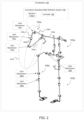
- FIG. 2 schematically illustrates the exoskeleton of FIG. 1 that has detected an anomalous operating state associated with an upper body limb structure, in accordance with an example of the present disclosure.
- FIG. 3 schematically illustrates the exoskeleton of FIG. 1 that has detected an anomalous operating state of a lower body limb, in accordance with an example of the present disclosure.
- FIG. 4 is a block diagram that illustrates example components included in the exoskeleton of FIG. 1 , and an anomalous operating state detection system of the exoskeleton of FIG. 1 , in accordance with an example of the present disclosure.
- FIG. 5 A is a flow diagram that illustrates an example method executed by an anomalous operating state detection system, in accordance with an example of the present disclosure.
- FIG. 5 B is a flow diagram that illustrates an example method executed by an anomalous operating state detection system, in accordance with an example of the present disclosure.
- FIG. 6 is a block diagram that illustrates example components included in a joint mechanism of an exoskeleton, in accordance with an example of the present disclosure.
- FIG. 7 is an isometric view of an exoskeleton, in accordance with an example of the present disclosure.
- FIG. 8 A is an isometric view of a joint mechanism of the exoskeleton of FIG. 7 , in accordance with an example of the present disclosure.
- FIG. 8 B is a partially exploded view of the joint mechanism of FIG. 7 A .
- FIG. 9 is a partially exploded view of a joint mechanism of the exoskeleton of FIG. 7 , in accordance with an example of the present disclosure.
- FIG. 10 is a partially exploded view of the joint mechanism of FIG. 9 .
- FIG. 11 is a cross sectional view exploded view of a portion of the joint mechanism of FIG. 9 .
- FIG. 12 is a flow diagram that illustrates an example method to prevent unsafe operation of an exoskeleton, in accordance with an example of the present disclosure.
- FIG. 13 is a flow diagram that illustrates an example method to prevent unsafe operation of an exoskeleton, in accordance with an example of the present disclosure.
- FIG. 14 is a flow diagram that illustrates an example method to prevent unsafe operation of an exoskeleton, in accordance with an example of the present disclosure.
- FIG. 15 is block diagram illustrating an example of a computing device that can be used to execute a method to prevent unsafe operation of an exoskeleton, in accordance with an example of the present disclosure.
- adjacent refers to the proximity of two structures or elements. Particularly, elements that are identified as being “adjacent” may be either abutting or connected. Such elements may also be near or close to each other without necessarily contacting each other. The exact degree of proximity may in some cases depend on the specific context.
- joint mechanism is referred to herein as a rotating mechanism that comprises a rotating joint of the exoskeleton. More specifically, a joint mechanism can comprise structural components or elements of the exoskeleton that are directly or indirectly rotatably connected or coupled to one another, and that rotate relative to one another about an axis of rotation, thus forming or defining a joint of the exoskeleton.
- joint mechanisms having differing structural arrangements of different types of structural components or elements rotatable relative to one another are contemplated herein, and as such, those specifically described and shown in the drawings are not intended to be limiting in any way.
- a joint mechanism can further comprise one or more objects, devices, and/or systems (e.g., actuator(s), sensor(s), clutch(es), transmission(s), and any combination of these), some of which can comprise or support the rotatably coupled structural components or elements of the joint (e.g., a rotary actuator having structural components or elements in the form of input and output members rotatable relative to one another that can couple to support structures of the exoskeleton, and that is operable to power the joint), or some of which facilitate rotation between two or more coupled structural components or elements (e.g., an actuated joint mechanism comprising a linear actuator operable to rotate relative to one another rotatably coupled structural components or elements in the form of support structures to provide a powered or actuated joint), or some of which indirectly rotatably couple or facilitate the rotatable coupling of the structural components or members (e.g., structural components or elements rotatably coupled together via a clutch or clutch
- a “joint mechanism” can comprise adjacent structural components or elements in the form of limb support structures that form all or part of the limbs of the exoskeleton, each having coupling portions that are configured to interface and fit with one another, and that are rotatably coupled together at a point of contact between the limb support structures, thus forming or defining a joint, wherein the limb support structures are able to rotate relative to one another about an axis of rotation of the joint mechanism (i.e., the joint axis of rotation) (e.g., a passive, non-powered exoskeleton joint in the form of or defined by two limb type support structures rotatably coupled together at respective coupling portions, such that they are rotatable relative to each other).
- the joint mechanism comprises a portion of the adjacent limb support structures, namely the respective coupling portions of the limb support structures.
- a “joint mechanism” can comprise structural components or elements in the form of input and output members of a system or device at the point of contact between the structural components or elements (such as those part of an actuator or of a clutch device or of a brake device, or an elastic element (e.g., spring or quasi-passive elastic actuator) or of a combination of these operating together), where the input and output members are rotatably coupled together via the actuator or clutch device or brake device, or spring element, or any of these in combination, thus forming or defining a joint, and where the input and output members are able to rotate relative to one another about an axis of rotation of the joint mechanism (i.e., the joint axis of rotation) (e.g., an actuated or powered exoskeleton joint in the form of or defined by an actuator comprising input and output members of a motor indirectly rotatably coupled together, such that they are rotatable relative to each other).
- an axis of rotation of the joint mechanism i.e., the joint axis
- the joint mechanism and particularly the input and output members of the joint mechanism, can be further coupled to respective limb type support structures, such that the limb type support structures are further caused to rotate with the input and output members, respectively, and relative to one another, about the axis of rotation of the joint mechanism.
- a “joint mechanism” can comprise some or all of the components described in the joint mechanism 106 of FIG. 6 , which is further discussed below, and which is further exemplified in the specific joint mechanisms shown and described below as pertaining to FIGS. 7 - 11 .
- the input and output members see FIG. 8 B, 236 a , 236 b
- the connecting limb type support structures FIG. 7 , 204 a , 204 b are not part of the “joint mechanism” 206 a as these are additional structural members coupled to the input and output members.
- FIGS. 1 - 3 illustrate a representative exoskeleton 100
- FIG. 4 is a block diagram illustrating an anomalous operating state detection system 102 of the exoskeleton 100 , in accordance with an example of the present disclosure.
- the exoskeleton 100 is a wireframe that is schematically representative of support structures, as well as respective joints of a plurality of joint mechanisms of a full body exoskeleton.
- an exoskeleton contemplated in the present disclosure may be a lower or upper body exoskeleton.
- FIG. 7 illustrates an example upper and lower body exoskeleton.
- U.S. patent application Ser. No. 17/114,460 filed Dec. 7, 2020 which is incorporated by reference herein in its entirety.
- the plurality of sensors 110 may include joint position sensor(s) 150 a (e.g., Hall effect sensor), a thermal sensor 150 b , motion sensor(s) 150 c (e.g., IMUs), current sensor(s) 150 d (e.g., phase current sensor), motor rotor position sensor 150 e , torque sensor 150 f , and/or other sensor(s) 150 g .
- joint position sensor(s) 150 a e.g., Hall effect sensor
- a thermal sensor 150 b e.g., motion sensor(s) 150 c (e.g., IMUs), current sensor(s) 150 d (e.g., phase current sensor), motor rotor position sensor 150 e , torque sensor 150 f , and/or other sensor(s) 150 g .
- motion sensor(s) 150 c e.g., IMUs
- current sensor(s) 150 d e.g., phase current sensor
- motor rotor position sensor 150 e
- the command signals referenced in the present disclosure may be generated by the controller 108 based on sensor output data from one or more of the sensors 150 a - g that are associated with the joint mechanism 106 .
- the exoskeleton 100 can comprise a plurality of sensors 110 a - n configured to generate sensor output data associated with at least one operational function of the exoskeleton 100 , as will be appreciated from the below discussion regarding the sensors of FIGS. 6 - 11 , for instance.
- the sensors 110 a - n can be part of the anomalous operating state detection system 102 , as further detailed below.
- the sensors 110 a - n can be coupled to various components of the exoskeleton 100 in a suitable manner, as further exemplified below, for generating and providing sensor output data via sensor output signals transmitted to a control system or controller 108 of the sensor suite discrepancy system 102 of the exoskeleton 100 .
- the sensors 110 a - n may include various types of sensors having various purposes for operational function of the exoskeleton 100 .
- a force moment sensor e.g., 6-axis load cell
- control system or controller 108 can be a bimodal or multi-modal controller that has the ability to control the operation of the exoskeleton responsive to user inputs.
- a contact displacement system is further described with reference to U.S. Pat. No. 8,849,457 B2, issued Sep. 30, 2014, which is incorporated by reference herein, and further described below regarding FIGS. 6 - 11 .
- an exoskeleton of the present disclosure may implement other suitable means for sensing user movement to effectuate movement of the exoskeleton according to the user movement.
- sensors of the suite of sensors 110 a - n may include a variety of different sensor types incorporated for different purposes associated with operating the exoskeleton 100 .
- the suite of sensors 110 a - n may include a variety of joint position sensors, motor rotor position sensors, joint torque sensors, thermal or temperature sensors, current sensors, and motion sensors such as Inertial Measurement Units (IMUs).
- IMUs Inertial Measurement Units
- a particular exoskeleton can support or incorporate dozens of sensors for a variety of different purposes, such as gravity compensation functions, feedback, and others, as exemplified herein.
- the controller 108 can be configured detect an anomalous operating state of the exoskeleton 100 to prevent an unsafe operation of the exoskeleton 100 , such as to avoid injury to the user/wearer, and/or to others that may be in the vicinity of the exoskeleton 100 during operation.
- An anomalous operating state can comprise an anomalous kinematic movement, a malfunction of the exoskeleton 100 , or any combination of these.
- a malfunction of the exoskeleton 100 can include one or more of a faulty or defective sensor, actuator, transmission, controller, processor, bearing, or other component or system, which can be one or more of a number of such components that may not be working properly.
- the controller 108 can detect such malfunction(s) and the effectuate or cause performance a remedial measure, ideally before such malfunction becomes a significant problem that can cause injury to persons or property. Examples of malfunctions are further discussed below.
- an “anomalous kinematic movement” can be defined as any unsafe or undesirable movement of the exoskeleton 100 based on the information provided by two or more sensors 110 a - n as associated with two or more joint mechanisms 106 a - n . That is, before the controller 108 transmits generated command signal(s) to actuator(s) of one or more joint mechanisms 106 a - n to effectuate a particular rotational movement about the one or more joint mechanisms 106 a - n (i.e., impending operational control of one or more joint mechanisms), the controller 108 will first determine whether such impending operational control is “safe or unsafe” to prevent an unsafe kinematic movement of the exoskeleton 100 that may result in injury.
- Such “safe or unsafe” kinematic movements can be based on known safe or unsafe movements that are programmed or stored into, or accessible by, the controller 108 based on acceptable exoskeleton movements.
- an unsafe movement could be an arm of an exoskeleton performing a kinematic movement that results in the user being undesirably impacted by the exoskeleton arm, such as being struck in the face, leg, or other part of the user's body by a portion of the exoskeleton.
- Another unsafe movement could be a kinematic movement that results in both legs of the exoskeleton being lifted upwardly at the same time, for instance, which may unbalance the exoskeleton to the point that it falls over and potentially injures the user.
- the controller 108 can effectuate a remedial measure (examples below) to prevent such unsafe movements. This can be achieved by the controller 108 monitoring two or more joint mechanism 106 a - n as they related to each other in terms of their current rotational positions and positions in space, and in terms of impending or future rotational position if the two or more joint mechanisms 106 a - n were actuated, as exemplified below regarding the detailed discussion of FIGS. 1 - 3 .
- the controller 108 can achieve the aforementioned detection of an “anomalous operating state” of the exoskeleton 100 in different ways.
- the controller 108 can be configured to monitor and receive the sensor output data generated by two or more sensors 110 a - n to determine an anomalous operating state.
- the controller 108 can be configured to monitor two or more command signals generated by the controller 108 that are based on processed sensor output data, wherein the controller can then determine whether any one of the command signals (to be transmitted to actuator(s)) may result in an unsafe anomalous kinematic movement.
- Each of these examples for detection of an anomalous operating state can be performed separately, meaning that they do not depend on each other.
- each of these means for detection of an anomalous operating state can be performed in at the same time or in parallel, which provides some level of redundancy to provide two layers of protection to prevent unsafe movements of the exoskeleton.
- an anomalous kinematic movement may be the result of a user unintentionally commanding the exoskeleton to perform an unsafe kinematic movement, or it may be the result of a malfunction, such as one caused by a faulty or non-functioning sensor, as discussed below.
- the upper body 103 a of the exoskeleton 100 includes a right arm 105 a having joint mechanisms 106 a - c (and others not labeled), each one being rotatably coupled together by two or more of the relative support structures 104 a - d .
- a safety envelope 107 a can be defined as a three dimensional zone or area about which the right arm 105 a can or should safely operate within.
- the controller 108 detects that one or more support structures and/or one or more joint mechanisms of the right arm 105 a are outside of this safety envelope 107 a , then that may be indicative of an anomalous operating state, such as a malfunction that requires performance of a remedial measure for safe operation.
- one or more sensors e.g., position sensors
- the knee joint mechanism 106 d also based on the sensed position of the knee joint mechanism 106 d
- the controller 108 has determined that the elbow joint mechanism 106 a is outside of the pre-determined and defined safety envelope 107 a , based on the sensed, known position of the elbow joint mechanism 106 a and the knee joint position 106 d relative to each other.
- a first joint mechanism i.e., 106 a
- a second joint mechanism e.g., 106 d
- some joint mechanisms provide sequentially coupled joints (e.g., 106 a and 106 b provide sequentially coupled joint mechanism).
- such anomalous operating state may be a malfunction of the position sensor (e.g., Hall effect sensor) supported by or associated with the elbow joint mechanism 106 a , which may be providing inaccurate or erroneous sensor output data for a number of reasons (e.g., faulty wiring, defective encoder, faulty sensing element, broken sensor mount, or other reasons).
- the controller 108 can receive the sensor output data of two or more sensors (joint position sensors), as associated with two joint mechanisms (elbow and knee), to determine the existence of an anomalous operating state indicative of a malfunction. The manner in which the controller 108 achieves such a determination is further detailed below.
- FIG. 2 shows a portion of the right arm 105 a being outside of the safety envelop 107 a , which, if such movement were performed by the exoskeleton, this would result in the user being struck in the face (i.e., support member 104 e may impact the user's face if the right arm 105 a were actuated to the position of FIG. 2 ).
- FIG. 2 shows a portion of the right arm 105 a being outside of the safety envelop 107 a , which, if such movement were performed by the exoskeleton, this would result in the user being struck in the face (i.e., support member 104 e may impact the user's face if the right arm 105 a were actuated to the position of FIG. 2 ).
- FIG. 2 shows a portion of the right arm 105 a being outside of the safety envelop 107 a , which, if such movement were performed by the exoskeleton, this would result in the user being struck in the face (i.
- FIG. 2 illustrates its position “if it were to be actuated” in the event that the controller 108 operated/actuated one or more joint mechanisms 106 a - c as commanded by the user (e.g., as a result of utilizing the aforementioned contact displacement system). That is, before the right arm 105 a is actively actuated to the position of FIG. 2 by the controller 108 , the controller 108 can detected beforehand that such movement of the exoskeleton arm would be an unsafe movement, and therefore the controller 108 can instead perform a remedial measure to prevent the unsafe movement and position of the arm as shown in FIG. 2 . Such remedial measure may include not actuating the joint mechanism(s) 106 a - c to such a position as shown in FIG.
- the controller 108 may include actuating the joint mechanism(s) 106 a - c to an acceptable/lesser degree so that the right arm 105 a remains within the bounds of the safety envelope 107 a .
- the manner in which the controller 108 achieves such determination and functionality is further detailed below.
- the lower body 103 b of the exoskeleton 100 includes a right leg 105 b having joint mechanisms 106 d - f (and others not labeled) rotatably coupled together by support structures 104 f - j (and others not labeled).
- a safety envelope 107 b can be a three dimensional zone or area about which the right leg 105 b can or should safely operate within. If, for example, the controller 108 detects that one or more support structures and/or one or more joint mechanisms of the right leg 105 b are outside of this safety envelope 107 b , then that may be indicative of an anomalous operating state, such as a malfunction or anomalous kinematic movement.
- the controller 108 can “look at” (compare or combine as discussed below) the sensor output data of two or more sensors (e.g., joint position sensors), as associated with at least two joint mechanisms ( 106 a - n ) to determine the existence of an anomalous operating state (e.g., one indicative of a malfunction), such as one where the right knee joint mechanism 106 d is physically within the left knee joint mechanism (not labeled),which is not illustrated in FIG. 3 . Indeed, FIG.
- FIG. 3 illustrates the other manner in which the controller 108 can detect an anomalous operating state by “looking at” two or more command signals to determine if an impending operation function of actuating joint mechanism(s) 106 d - f would result in an unsafe kinematic movement, such as the right foot (structural support 104 j ) of the exoskeleton 100 impacting the user's left foot and/or the left foot structure of the exoskeleton 100 .
- FIG. 3 is similar to the example discussed above regarding FIG. 2 .
- each safety envelope 107 a and 107 b may not be a perfectly, well-defined envelope as illustrated in the drawings, and may not necessarily be known or generated by the controller 108 in the manner illustrated. Rather, the safety envelopes may be defined by the particular joint positions of two or more of all of the particular joint mechanisms 106 a - n of the exoskeleton 100 , and at a particular point in time of operating the exoskeleton 100 . To this end, it should be appreciated that the safety envelope 107 a (and other safety envelopes) may be constantly changing based on the rotational position of two or more joint mechanisms 106 a - n as related to each other, and as relative to acceptable, safe kinematic movements of the exoskeleton 100 .
- each exoskeleton limb may have their own safety envelope that is dynamically changing depending on the movement and position of the joint mechanisms and that defines the safe operating area or volume about which each exoskeleton limb can and should operate within for safe operation of the exoskeleton.
- the anomalous operating state detection system 102 exemplified in FIG. 4 can comprise the controller 108 and the plurality sensors 110 a - n .
- FIG. 4 illustrates one sensor associated with each joint mechanism of the exoskeleton 100 , for purposes of simplification of the examples discussed below, it will be appreciated that a plurality of sensors can be associated with each joint mechanism, as discussed below regarding FIG. 6 .
- association with this means that the sensor(s) is used in a manner that it measures a characteristic of the respective joint mechanism, such as a joint position sensor attached to a rotational component of a particular joint mechanism, as exemplified in FIG. 7 - 11 , for instance.
- the controller 108 can be considered a computing device or a control system, which can include a malfunction module 120 , an anomalous kinematic movement module 124 , a remedial measure module 126 , a data store 130 , one or more processors 132 , one or more memory module(S) 134 , and other system components discussed herein.
- FIGS. 5 A and 5 B each illustrate a flow diagram representative of a method as associated with and executed by the various modules of controller 108 of the anomalous operating state detection system 102 of FIG. 4 .
- the various processes and/or other functionality contained within the controller 108 may be executed on/by the one or more processors 132 that are in communication with one or more memory modules 134 .
- the controller 108 can include a number of computing devices that are arranged, for example, in one or more server banks or computer banks, or other arrangements.
- the term “data store” may refer to any device or combination of devices capable of storing, accessing, organizing and/or retrieving data, which may include any combination and number of data servers, relational databases, object oriented databases, cluster storage systems, data storage devices, data warehouses, flat files and data storage configuration in any centralized, distributed, or clustered environment.
- the storage system components of the data store 130 may include storage systems such as a SAN (Storage Area Network), cloud storage network, volatile or non-volatile RAM, optical media, or hard-drive type media.
- the data store 130 may be representative of a plurality of data stores 130 as can be appreciated. API calls, procedure calls, inter-process calls, or other commands can be used for communications between the modules.
- FIG. 5 A illustrates the aforementioned manner in which the controller 108 can “look at” sensor output data to determine or detect an anomalous operating state, such as a malfunction and/or an anomalous kinematic movement.
- Sensor output data 135 generated by at least some of the sensors 110 a - n can be received and processed (by the processors(s) 132 ), and then the malfunction module 120 can be configured to determine whether the sensor output data 135 satisfies an error condition in relation to at least one defined criterion (or a plurality of defined criterion), whereby the existence of the error condition is indicative of an anomalous operating state of the exoskeleton.
- a joint position sensor e.g., 110 a , such as a Hall effect sensor S 1 of FIG. 8 A
- sensor output data from a joint position sensor (e.g., 110 a , such as a Hall effect sensor S 1 of FIG. 8 A ) associated with or supported by the elbow joint mechanism 106 a indicates that the rotational position of the elbow joint is at 125 degrees (or equivalent radians)
- sensor output data from a joint position sensor (e.g., 110 c ) of the shoulder joint mechanism 106 c (flexion/extension) indicates that the rotational position of the shoulder joint mechanism 106 c is at 180 degrees
- this may satisfy an error condition in relation to a defined criterion or a plurality of defined criterion.
- a defined criterion can comprise an acceptable/unacceptable relationship between the rotational positon of two joints of a particular limb. For instance, it may be known (and therefore programmed in the controller as a defined criterion) that it is unsafe to have a shoulder flexed backwardly so far behind the body (i.e., 180 degrees) along with the elbow joint being bent upwardly to such a degree (i.e., 125 degrees), because it may place a large strain on the user because such limb position is beyond a comfortable or safe position (e.g., outside of the safety envelope 107 a and therefore may cause injury).
- the controller 108 can be configured to never rotate the joint mechanisms 106 a and 106 c to such an unsafe position (being outside of the safety envelope), the controller 108 can effectively assume or know that there is a malfunctioning component. For instance, unbeknownst to the user (and the controller 108 ), assume that the rotational position sensor associated with the shoulder joint mechanism 106 c is defective and therefore should be outputting an actual rotational position of 90 degrees (and not be outputting the inaccurate/erroneous reading of 180 degrees).
- the malfunction module 120 has determined that the sensor output data 135 (i.e., rotational positions of the joint mechanisms 106 a and 106 c ) indeed satisfies an error condition in relation to a particular defined criterion (i.e., the shoulder joint being positioned “too high” relative to the elbow joint position and outside the safety envelope), which therefore indicates the existence of an anomalous operating state being a malfunction of the exoskeleton (i.e., faulty or defective sensor).
- a particular defined criterion i.e., the shoulder joint being positioned “too high” relative to the elbow joint position and outside the safety envelope
- the particular defined criterion can be a threshold limit or range as related to the rotational position of two or more joint mechanisms. For instance, if the rotational position the elbow joint mechanism 106 a is between 90 and 130 degrees, then the shoulder joint mechanism 106 c cannot exceed 100 degrees (i.e., the defined criterion), otherwise an error condition is satisfied, which may indicate a malfunction of a sensor (e.g., sensor 110 c ).
- the same principle can apply to some or all of the joint mechanism 106 a - n , such that each joint mechanism 106 a - n must be within a particular range of rotational degrees relative to the particular rotational degrees of one or more other joint mechanisms.
- a particular defined criterion (related to the determination of the malfunction module 120 ) can include that the fact that the sensed spatial position of any joint mechanism should never be within a certain distance from any other joint mechanism (which may indicative of a malfunction of a sensor or other component, as exemplified above regarding FIG. 1 ). This can also be the case with the particular position of the support members 104 a - n relative to each other and relative to one or more of the joint mechanisms 106 a - n .
- at least some of the support structures 104 a - n can each support an IMU (inertia measurement unit) sensor for generating sensor output data associated with the three dimensional spatial position of the support structure.
- IMU inertia measurement unit
- none of the sensors should be returning sensor output data that indicates one of the joint mechanisms (e.g., a first joint mechanism), for example one or more of the support structures of the joint mechanisms, as being “physically inside of” another joint mechanism (e.g., a second joint mechanism), such as one or more of the support structures of the other joint mechanism (i.e., at least part of the joint mechanisms occupying at least part of the same space or spatial position), because that is physically impossible, so if the controller 108 determines that the sensor output data indicates this anomalous operating state, this may be indicative of a sensor (e.g., IMU) malfunction.
- a sensor e.g., IMU
- the anomalous kinematic movement module 124 can be configured to combine the sensor output data 135 from at least two sensors 110 a - n , and to determine whether the combination of the sensor output data from the at least two sensors 110 a - n satisfies an error condition in relation to at least one defined criterion (or a plurality of defined criterion), whereby the existence of the error condition is indicative of an anomalous operating state of the exoskeleton (i.e., an anomalous kinematic movement, as introduced above).
- the processes executed by the anomalous kinematic movement module 124 can occur in parallel with the processes executed by the malfunction module 120 . As exemplified above regarding the discussion of FIG.
- the anomalous kinematic movement module 124 can “look at” (compare or combine as discussed below) the sensor output data associated with the elbow joint mechanism 106 a and the sensor output data associated with the shoulder joint mechanism 106 b (thereby combining or comparing the sensor output data) to detect an anomalous operating state, which may indicate an anomalous kinematic movement that may be unsafe (which is determined before the joint mechanisms 106 a and 106 c are actuated). For instance, assume that a first force moment sensor associated with the joint mechanism 106 a accurately generates sensor output data that indicates that the user desires to rotate his elbow to lift a load, such that the joint mechanism 106 a should be actuated to have a torque output of 90 Nm.
- a second force moment sensor associated with the shoulder joint mechanism 106 b (medial/lateral rotation) inaccurately generates sensor output data that indicates that the user desires to medially rotate his shoulder, such that the joint mechanism 106 a would be actuated to have a torque output of 25 Nm.
- the second force moment sensor is defective and providing erroneous sensor data, and therefore the joint mechanism 106 b should not be actuated at all, because the resulting movement would culminate in a portion of the right arm 105 a being situated outside of the safety envelope 107 a , and thereby would be an unsafe movement.
- the controller 108 can “look at” the impending movement that would otherwise be effectuated by the controller 108 , and can then determine that the combination of the sensor output data from the first and second force moment sensors indeed satisfies an error condition in relation to at least one defined criterion, as further exemplified here, to prevent unsafe operation of the exoskeleton.
- the unsafe movements of the exoskeleton 100 can be stored and retrieved as acceptable kinematic movement data 136 of the data store 130 .
- the acceptable kinematic movement data 136 can include known unacceptable or unsafe kinematic movements that result in certain combinations of movement effectuated by two or more joint modules 106 a - n that would otherwise be unsafe movements. For instance, it may be unsafe to have the lower legs of the exoskeleton spread apart too far from each other, which could cause injury to the user.
- the acceptable kinematic movement data 136 can include a defined criterion being that the joint rotational position of a first hip joint mechanism (for left hip flexion/extension) cannot exceed an upper bound limit (e.g., 90 degrees) relative to the joint rotational position of a second hip mechanism (for right hip flexion/extension), because exceeding this upper bound limit may result in an unstable/unbalanced exoskeleton and/or injury to the user.
- an upper bound limit e.g. 90 degrees
- the acceptable kinematic movement data 136 can include any number of defined criterion associated with the position of any combination of joints and/or support structures as related to each other that would be unsafe movements or positions.
- the remedial measure module 126 may be configured to execute one or more remedial measures to prevent unsafe operation of the exoskeleton 100 , as further discussed herein.
- the controller 108 can “look at” two or more command signals 137 a - n to determine or detect an anomalous operating state, such as a malfunction and/or an anomalous kinematic movement.
- sensor output data generated by force moment sensors at some of the joint mechanism 106 a - n can be received by the controller 108 and then processed according to known signal processing techniques for purposes of generating command signals that are then transmitted to the actuators (e.g., a certain voltage sent to an EM motor) of the respective joint mechanisms as part of a closed loop control system to appropriately operate the exoskeleton.
- the controller 108 can “look at” or compare two or more command signals, each for controlling at least one operational aspect at least one joint mechanism, to determine if the resulting actuation of the at least one joint mechanisms would constitute an unsafe kinematic movement that would situate one or more parts of the exoskeleton outside of a particular safety envelope (e.g., 107 a , 107 b ), for instance.
- a particular safety envelope e.g., 107 a , 107 b
- the controller 108 has generated a first command signal 137 a for impending operational control of the elbow joint mechanism 106 a to actuate its EM motor with a supplied voltage that results in an output of 90 Nm (i.e., to lift a payload).
- the impending operational control of the elbow joint mechanism 106 a includes impending or subsequent control of the elbow joint mechanism 106 a that would occur only if the command signal 137 a were in fact transmitted to the EM motor to rotate the joint (or transmitted to a local encoder or controller of the joint mechanism).
- the controller 108 has also generated a second command signal 137 b to be transmitted to the shoulder joint mechanism 106 b to actuate its EM motor with a voltage that results in an output of 25 Nm (i.e., “impending operational control” of the shoulder joint mechanism 106 b ).
- the controller 108 causes execution of a remedial measure to prevent such unsafe movement of the exoskeleton 100 (instead of transmitting the command signals 137 a and 137 b to the joint mechanisms 106 a and 106 b ).
- the controller 108 has combined or compared the command signals 137 a and 137 b and determined that the command signals 137 a and 137 b , when looked at together, would otherwise result in an anomalous kinematic movement that should not be performed. Based on this determination, the controller 108 has prevented an otherwise unsafe action or movement before it occurs to protect the safety of the user, the exoskeleton, and others around the exoskeleton.
- the particular defined criterion can be a threshold limit or range as related to the rotational position of the joint mechanisms 106 a and 106 b (if the command signals 137 a and 137 b were transmitted to the joint mechanisms 106 a and 106 b for actuation). For instance, if the future rotational position the elbow joint mechanism 106 a is going to be between 90 and 130 degrees, then the shoulder joint mechanism 106 c should not be actuated to exceed 100 degrees when actuated from its current/known position, otherwise an error condition is satisfied.
- the same principle can apply to some or all of the joint mechanism 106 a - n , such that a future position of two or more joint mechanism 106 a - n must be within a particular range of rotational degrees relative to the particular rotational degrees of one or more other joint mechanisms.
- the joint mechanisms 106 a - n of the exoskeleton 100 will not be actuated to unsafe positions relative to each other, relative to the user, and relative to particular support structures, so that the joint mechanisms 106 a - n can operate safety and in harmony prior to any impending actuation or movement that may be unsafe.
- the remedial measure module 126 may be configured to execute one or more remedial measures to prevent unsafe operation of the exoskeleton 100 .
- the controller 108 may transmit a command signal to the actuator of a joint mechanism for effectuating some amount of acceptable/safe rotation about the joint mechanism.
- the controller 108 may instead transmit an appropriate command signal that would only cause 40 degrees of actual rotation so that the right arm 105 a stays within the particular safety envelope 107 a.
- the controller 108 may transmit a command or other signal to a clutch or brake device (e.g., 144 of FIG. 6 , or see clutches of FIGS. 9 - 11 ) for an appropriate/safe function, such as entirely disengaging the clutch or brake device, partially engaging the clutch or brake device (while also actuating the actuator), or fully engaging the clutch or brake device (to “freeze” up the joint).
- a clutch or brake device e.g., 144 of FIG. 6 , or see clutches of FIGS. 9 - 11
- an appropriate/safe function such as entirely disengaging the clutch or brake device, partially engaging the clutch or brake device (while also actuating the actuator), or fully engaging the clutch or brake device (to “freeze” up the joint).
- the controller 108 may perform this remedial measure for some or all of the other possible brakes or clutches of some or all of the joint mechanisms of the exoskeleton. Examples of clutches or brakes are provided below regarding FIGS. 6 - 11 .
- the controller (e.g., 108 , 208 ) may be configured to execute or perform a remedial measure using a remedial measure module 128 of the controller, which may be based on the selection of the preferred substitute sensor effectuated by the preferred sensor selector module 126 (see e.g., the discussion below regarding FIGS. 7 - 10 ).
- the remedial measure module 128 may provide at least one notification to indicate to the user (and/or to others) of the possibility of a defect or malfunction of the exoskeleton.
- the at least one notification can be a visual notification, an audible notification, a haptic notification, or any combination of these.
- the notification can be provided as an audio signal to the user, it can be displayed on a screen visible to the user, it can comprise a vibration of one or more components of the exoskeleton sensed by the user, or others as will be recognized by those skilled in the art. Based on such notification, the user can then discontinue use of the exoskeleton, or return it to a docking station, or actively switch to another control policy.
- the remedial measure module 128 can ensure that command signals are not transmitted to some or all of the actuators of the joint mechanism 106 a - n.
- the remedial measure module 128 may cause one or more joint mechanisms to be autonomously actuated to a “safe position”, such as a generally upright position of the exoskeleton so that the user can safely step out of the exoskeleton to allow it to be diagnosed and fixed.
- a “safe position” such as a generally upright position of the exoskeleton so that the user can safely step out of the exoskeleton to allow it to be diagnosed and fixed.
- This is “autonomous” because it is independent of any system that functions to effectuate movement of the exoskeleton based on user control of the exoskeleton (e.g., a contact displacement user actuation system).
- the remedial measure module 128 may be configured to ignore or shut off or override the contact displacement system of the exoskeleton, and instead cause autonomous movement of the exoskeleton independent of movement of the user by actuating the joint mechanisms to a pre-defined, safe position.
- the remedial measure module 128 may also control one or more brake or clutch devices once the exoskeleton is autonomously positioned in a desired safety position, and then shut off any command signals to all of the motors of the joint mechanisms to ensure the exoskeleton is not accidentally actuated unsafely.
- a particular joint mechanism 106 may include some or all of the components shown (see also FIGS. 7 - 11 for structural features of example joint mechanisms).
- the joint mechanism 106 may include an actuator 140 , such as a pneumatic, electric, or hydraulic actuator.
- One or more transmissions 142 may be operatively coupled to the actuator 140 , such as gear train(s), belt(s), etc.
- the joint mechanism 106 may further include a clutch or brake device 144 , such as friction disks or plates for restricting or limiting rotation about the joint (which may be a remedial measure, discussed below).
- the joint mechanism 106 may further comprise an elastic element 146 , such as a rotary air spring, torsion spring, or other suitable elastic element operable to store and release energy.
- an elastic element 146 such as a rotary air spring, torsion spring, or other suitable elastic element operable to store and release energy.
- a particular joint mechanism may be passive (i.e., not having an actuator), such as a joint mechanism having a clutch or brake device and an elastic element (e.g., FIGS. 8 A- 10 ), whereby the clutch or brake device is controllable via the controller 108 to engage or disengage application of the elastic element, and configured to fully “freeze” or brake the joint, in one example of a remedial measure.
- the joint mechanism 106 can include some or all of the features of the tunable actuator joint modules discussed in U.S. patent application Ser. No. 15/810,108, filed Nov. 12, 2017, which is incorporated by reference herein, and as further exemplified in FIGS. 7 - 11 .
- a force moment sensor 148 may be coupled to a support structure (or strap or other component) adjacent the joint mechanism 106 , and positioned to be in contact with a human element of a user wearing the exoskeleton 100 , for instance (see e.g., FIGS. 7 and 8 A ).
- the force moment sensor 148 may be part of a contact displacement system, in which the sensor 148 transmits output signals to the controller 108 in response to user movement so that the controller 108 can effectively control functions of the joint mechanism 106 , as discussed above and further below regarding FIGS. 7 - 11 .
- the plurality of sensors 110 may include joint position sensor(s) 150 a (e.g., Hall effect sensor), a thermal sensor 150 b , motion sensor(s) 150 c (e.g., IMUs), current sensor(s) 150 d (e.g., phase current sensor), motor rotor position sensor 150 e , torque sensor 150 f , and/or other sensor(s) 150 g .
- joint position sensor(s) 150 a e.g., Hall effect sensor
- a thermal sensor 150 b e.g., motion sensor(s) 150 c (e.g., IMUs), current sensor(s) 150 d (e.g., phase current sensor), motor rotor position sensor 150 e , torque sensor 150 f , and/or other sensor(s) 150 g .
- motion sensor(s) 150 c e.g., IMUs
- current sensor(s) 150 d e.g., phase current sensor
- motor rotor position sensor 150 e
- the command signals referenced in the present disclosure may be generated by the controller 108 based on sensor output data from one or more of the sensors 150 a - g that are associated with the joint mechanism 106 .
- FIG. 6 illustrates an exoskeleton 200 having a sensor discrepancy detection system 202 , in accordance with an example of the present disclosure.
- the exoskeleton 200 can have the same features and functionality as the exoskeleton 100 described above, such as have the anomalous operating state detection system 102 (labeled here as 101 , and which can include controller 208 and sensors S 1 -Sn, similarly as shown and described in the example of FIG. 1 ).
- the exoskeleton 200 can further include the various modules and their functionality as described in FIGS. 4 - 5 B (e.g., malfunction module, anomalous kinematic movement module, remedial measure module).
- the exoskeleton 200 can comprise a plurality of support structures 204 a - n (not all labeled) and a plurality of joint mechanisms 206 a - n (not all labeled) rotatably coupling together the support structures 204 a - n in accordance with pre-determined desired or required degrees of freedom within the exoskeleton 100 that correspond to the various degrees of freedom of a human operator.
- an exoskeleton can be configured in a number of different ways and with a number of degrees of freedom. As such, the exoskeleton configurations described herein, and shown in the drawings are not intended to be limiting in any way.
- each joint mechanism 206 a - n rotatably couples two or more adjacent support structures 204 a - n to define a joint rotatable about an axis of rotation that facilitates movement of the exoskeleton 200 in one or more degrees of freedom corresponding to one or more degrees of freedom of a human operator.
- the joint mechanism 206 a can rotatably couple support structures 204 a and 204 b , and can be operable to rotate about an axis of rotation associated with knee flexion/extension of the exoskeleton 200 that corresponds to knee flexion/extension of a human operator.
- the joint mechanism 206 a can have an actuator, such as an electromagnetic motor, as part of a drive system for actuating the joint, such as exemplified in FIGS. 8 A and 8 B and further discussed below.
- the exoskeleton 200 and the sensor discrepancy detection system 202 can comprise a suite of sensors S 1 -Sn configured to generate sensor output data associated with at least one operational function of the exoskeleton 200 .
- the sensors S 1 -Sn can be coupled to various portions or aspects of the exoskeleton 200 , as further exemplified herein, for producing sensor output data transmitted via sensor output signals to a control system or controller 208 of the sensor discrepancy detection system 202 of the exoskeleton 200 .
- a force moment sensor 248 (e.g., 6-axis load cell) associated with the joint mechanism 206 a can be provided as part of a contact displacement system to sense movement of a user to effectuate movement of the exoskeleton 200 that at least partially corresponds to movement in accordance with the degrees of freedom of the user when the exoskeleton 200 is being worn or donned by the user, similarly as discussed above regarding FIGS. 1 - 5 .
- the force moment sensor 248 can be coupled to the support structure 204 a proximate a shin/leg strap of the exoskeleton 200 .
- each joint mechanism 206 a - n can include or be associated with a force moment sensor coupled to a portion of the exoskeleton to be in contact with (or proximate) a human element of a user wearing the exoskeleton 200 .
- a plurality of sensors S 1 -S 4 of the suite of sensors S 1 -Sn can be identified as a sensor group 210 a associated with the joint mechanism 206 a .
- FIGS. 8 A and 8 B further illustrate possible sensors S 1 -S 4 and their possible positions on the exoskeleton 200 as being associated with the joint mechanism 206 a .
- the joint mechanism 206 a is shown inverted in FIG. 8 B . Connections between the various sensors and the controller are omitted to avoid obscuring the invention.
- suitable wired or wireless connections are provided to communicate sensor data from each sensor to the controller.
- a suitable power source (not shown) can be provided for powering operations of the exoskeleton.
- the power source can provide a source of electrical power for electronic components, such as the sensors, the controller, or other components.
- the power source can comprise a battery, a fuel-based power generator or a tethered connection to an external power source.
- the exoskeleton can also include a source of pressurized air or hydraulic fluid, as well as associated fluid lines, valves, busses, etc.
- the power source and the source of pressurized air can be carried on-board the exoskeleton or can be provided from a remote base unit by means of a tether arrangement.
- the controller 208 can be configured to determine a discrepancy between sensor output data of two or more sensors of a group of sensors, such as sensors S 1 -S 4 of the sensor group 210 a , and can be configured to recruit at least one sensor S 1 -S 4 of the sensor group 210 a as a substitute sensor to account or compensate for discrepant sensor output data of one of the sensors S 1 -S 4 .
- a target sensor S 1 can comprise a joint position sensor 222 (e.g., Hall effect sensor of FIG. 8 A ) that transmits rotational position data via sensor output signals to the controller 208 for processing to facilitate determination of a rotational position of the joint defined by the joint mechanism 206 a . As schematically shown in FIGS.
- an auxiliary sensor S 2 can be supported by or coupled to the joint mechanism 206 a , such as a torque or force sensor, motor rotor position sensor, or other possible auxiliary sensor discussed herein.
- Another auxiliary sensor S 3 can be supported by or coupled to the first support structure 204 a , such as an inertial-based motion sensor (e.g., an IMU).
- An auxiliary sensor S 4 can be supported by or coupled to the second support structure 204 b , and can comprise a second inertial-based motion sensor, such as an inertial measurement unit (IMU). Note that support structure 204 b is hidden from view in FIG. 8 A , but see FIG. 7 showing the second support structure 204 b that could support the auxiliary sensor S 4 . Further details of the sensors S 1 -S 4 of the sensor group 210 a are further discussed below, following the below details of the joint mechanism 206 a.
- the joint mechanism 206 a can include the same features of the tunable actuator joint module 109 a discussed in U.S. patent application Ser. No. 15/810,108, filed Nov. 12, 2017, which is incorporated herein, and also detailed below. More specifically, the joint mechanism 206 a can be configured to recover energy during a first gait movement and then release such energy during a second gait movement to apply an augmented torque to rotate the knee joint about the degree of freedom in parallel with a torque applied by a primary actuator of the joint mechanism 206 a , similarly as discussed in incorporated U.S. patent application Ser. No. 15/810,108.
- the joint mechanism 206 a comprises a primary actuator 232 and an elastic element, such as a quasi-passive elastic actuator 234 , structurally coupled to each other and operable with one another to provide torque to the joint.
- An input member 236 a and an output member 236 b (coupled to the quasi-passive elastic actuator 234 ) can rotate relative to one another about an axis of rotation 237 to achieve a flexion/extension degree of freedom of the exoskeleton 200 corresponding to a degree of freedom of a human joint, namely the flexion/extension of the knee joint.
- the input and output members 236 a and 236 b may be the respective first and second support structures 204 a and 204 b of FIG. 7 , but are shown in FIG. 8 B as generic members coupled to the input and output of the joint mechanism 206 a for purposes of illustration.
- the primary actuator 232 e.g., a geared electric motor
- the quasi-passive elastic actuator 234 e.g., a rotary pneumatic actuator
- the quasi-passive elastic actuator 234 is selectively operable to generate a braking force, or to apply an augmented torque to the output member 236 b along with the torque applied by the primary actuator 232 to actuate the joint, such as during a certain portion of a gait movement.
- the quasi-passive elastic actuator 234 is operable or controllable by a control system (e.g., a valve assembly) to selectively store energy or to selectively generate a braking force (in an elastic state or a semi-elastic state) upon a first rotation of the input member 236 a , and to selectively release that energy (while still in the elastic or semi-elastic state) during a second or subsequent rotation of the input member 236 a .
- a control system e.g., a valve assembly
- Such functionality may be effectuated by the controller 208 in concert with the valve assembly.
- the first rotation of the input member 236 a can be achieved via active actuation of the primary actuator to actuate the tunable joint module and to cause rotation of the joint module (and any structural supports coupled thereto).
- the first rotation of the input member 236 a can be achieved passively, namely by exploiting any available gravitational forces or external forces acting on the robotic system suitable to effectuate rotation of the input member 236 b within the tunable actuator joint module (e.g., such as a lower exoskeleton being caused to perform a sitting or crouching motion, which therefore affects rotation of the various tunable joint modules in the exoskeleton).
- the quasi-passive actuator in parallel with a primary actuator provides the tunable joint module with compliant gravity compensation. Once the energy is stored, it can be released in the form of an augmented torque to the output member 236 b , or it can be used to brake or restrict further rotation.
- the quasi-passive elastic actuator 234 can further be configured, upon a third or subsequent rotation(s), to neither store nor release energy, the quasi-passive elastic actuator 234 being caused to enter an inelastic state.
- the input and output members 236 a and 236 b are caused to enter a “free swing” mode relative to each other, meaning that negligible resistance exists about the quasi-passive elastic actuator 234 (this is so that the actuator 234 does not exhibit a joint stiffness value that would restrict rotation of the input member 236 a relative to the output member 236 b , such as would be desired during a leg swing phase of a gait cycle of the robotic device).
- the quasi-passive elastic actuator 234 is switchable between the elastic state and the inelastic state, such that the quasi-passive elastic actuator 234 applies an augmented toque (in the elastic state) in parallel with a torque applied by the primary actuator 234 .
- This combined torque functions to rotate the output member 236 b relative to the input member 236 a in a more efficient manner as less torque is required by the primary actuator to perform the specific gait phase, thereby reducing the power requirements/demands of the primary actuator 234 , as further detailed below.
- the quasi-passive elastic actuator 234 can be structurally mounted to the primary actuator 232 by a first mounting plate 238 a and a second mounting plate 238 b , each positioned on either side so as to constrain the primary actuator 232 and the quasi-passive elastic actuator 234 234 in a “sandwich” state.
- the first mounting plate 238 a is mounted to a housing mount 240 of the primary actuator 232 via a plurality of fasteners 242 (with spacers there between).
- the first mounting plate 238 a comprises a primary aperture 244 a that rotatably supports a collar bearing of the primary actuator 232 , and comprises a secondary aperture 244 b that rotatably receives a collar bearing supported by the quasi-passive elastic actuator 234 .
- the primary actuator 232 can comprise a housing mount 240 to house and structurally support the primary actuator 232 .
- the primary actuator 232 comprises a motor 278 , such as a high-performance Permanent Magnet Brushless DC motor (PM-BLDC).
- PM-BLDC Permanent Magnet Brushless DC motor
- the motor described above and shown in the drawings is not intended to be limiting in any way. Indeed, other motors suitable for use within the primary actuator 232 are contemplated herein, as are various other types of actuators, such as hydraulic actuators.
- the motor 278 can comprise a central void that receives a gear train or transmission, such as a planetary transmission 286 .
- a rotatable transfer wheel 298 can be fastened to the rotor of the motor 278 to transfer rotation from the rotor of the motor 278 to a sun gear of the transmission 286 about the axis of rotation 203 .
- the rotor rotates about axis 203 , which causes the transfer wheel 298 to rotate, which thereby causes the sun gear to rotate, which causes an output shaft 209 to rotate primary pulley 216 .
- the primary pulley 216 is rotatably coupled to a transmission belt 224 , which is rotatably coupled to a gear ring 268 that ultimately causes rotation of the joint via a vane device coupled to the output member 236 a (see U.S. patent application Ser. No. 15/810,108 incorporated herein for further details on the vane device and valve assembly).
- a sensor plate 220 can be fastened to an outer side of the housing 240 , and has an aperture that supports the position sensor 222 (i.e., target sensor S 1 , in this example).
- the position sensor 222 is adjacent the transfer wheel 298 , which has an aperture through to the sun gear (of the transmission 286 ) that facilitates the position sensor 222 to determine the rotational position of the sun gear.
- the sensor output data produced by the position sensor 222 can be transmitted via an output signal to the controller 208 for processing to determine the rotational position of the joint.
- the position sensor 222 can be any suitable sensor, such as a 13-bit Hall effect sensor, magnetic encoder, optical encoder, resolver, potentiometer, etc.
- joint position sensor may dictate the possible location on the joint mechanism that such sensor is mounted to.
- the particular rotational position of the knee joint mechanism is relevant for determining and controlling actuation of the joint via control of the motor 278 based on the contact displacement system.
- the motor 278 can comprise a stator and rotor rotatable relative to each other (in a typical fashion for commercially available frameless brushless motors), and the auxiliary sensor S 2 , such as a motor rotor position sensor, can be operably coupled to or proximate to the motor 278 for producing sensor output data associated with a rotational position of the rotor relative to the stator.
- the auxiliary sensor S 2 such as a motor rotor position sensor
- the controller 208 can execute a transformation calculation that transforms the sensor output data from the sensor S 2 into a format or value that can be an estimate of the rotational position of the joint defined by the joint mechanism 206 a (in the event the target sensor S 1 provides data that “fails” testing processes, as exemplified below).
- Such transformation of the sensor output data associated with the auxiliary sensor S 2 can produce “transformed sensor output data” that can be compared against the sensor output data of the target sensor S 1 .
- Such calculation may need to take into consideration the gear reduction provided by a transmission (e.g., planetary transmission 286 , and/or belt 224 ).
- Other transmissions or couplers may have a particular stiffness value that may need taken into consideration when determining such joint position.
- the data provided by the rotor position sensor can be used: (1) to control the commutation of the motor phases, and (2) for closed-loop position/velocity control of the rotor in control policies such as software stop limits, for instance. If a rotor position sensor malfunctions, it can render the motor unusable as a power source, or it may generate random commutations sequences, or it may make the joint simply unresponsive. Note that, if the problem is detected, the motor can still be used as a controlled passive brake, for instance.
- the rotor position sensor can be used as an auxiliary sensor to a target sensor (e.g., joint position sensor).
- a target sensor e.g., joint position sensor
- auxiliary sensors that act as a “back-up” or substitute sensor if the rotor position sensor is malfunctioning.
- a joint position sensor can be used as an auxiliary sensor to the rotor position sensor being the target sensor.
- ⁇ J f tr ( ⁇ M , T J , T M , ⁇ M ), where f tr is a function that encapsulate the characteristics of the transmission, including but not limited to: gear ratio (NGR), compliance, friction, backlash, periodic systematic error (e.g.
- ⁇ M is to rotor position
- T J is the joint torque (the torque applied by the transmission to the joint, and as a rule it may be the total joint torque minus the torque contributed by the elastic element coupled to the output joint)
- T M is the rotor (motor torque)
- ⁇ M is the rotor speed (also referred to as W M ).
- a motor rotor position sensor has a primary sensing functionality of producing data associated with the rotational position of the rotor relative to the stator (or other component), which is different than the primary sensing functionality of the target sensor S 1 , for instance.
- the motor rotor position sensor as an auxiliary sensor to the target sensor, can generate sensor output data that can be transformed by the sensor suite discrepancy detection system 202 for purposes of allowing the motor rotor position sensor to function as a possible substitute sensor for the target sensor.
- the controller 208 may include available software libraries tailored for “sensorless” control of the motor (i.e., rotor position state estimator) to measure the rotor position of the motor.
- the implementation of a rotor position state estimator could: provide the means for an actuator to continue operating in the event of a malfunction of the rotor position sensor where the rotor position sensor is relied upon as a complimentary sensor to the joint position sensor; allow joint position to be estimated by taking into account characteristics of a transmission (e.g., the transmission(s) discussed herein); allow rotor speed to be computed and used on one mechanism to determine if the primary joint position and rotor position sensors are working properly; and as a by-product of the state estimation algorithm to provide an estimate of the motor phase resistance, which, in turn, could be used to estimate motor coil temperature.
- the use of state estimator algorithms and software for sensorless motor control can serve as another “back-up” mechanism for a joint position sensor if it is defective or malfunctioning, thereby providing sensor redundancy.
- another possible auxiliary sensor can comprise a torque sensor operatively coupled to one or more components of the joint mechanism 206 a in a suitable manner for producing sensor output data associated with a torque applied to the joint by the motor.
- a joint torque sensor can be coupled to the shaft 209 , or to the sun gear of the transmission 286 , or at or near the input or output members of the joint mechanism 206 a , or to any other rotational component that generates or experiences a torque of the exoskeleton for purposes of sensing torque.
- the primary sensing functionality of the torque sensor is to produce data regarding a torque value generated or experienced by a component of the joint mechanism 206 a to appropriated close the loop on a torque command, such as in the case of its use with a force moment sensor (e.g., a 6-axis load cell) as part of a contact displacement system, as mentioned above.
- a force moment sensor e.g., a 6-axis load cell
- the same or additional torque sensor(s) may also be used for gravity compensation purposes of the exoskeleton itself, and also during tasks such as acquiring and lifting a load.
- a joint torque sensor may also be used to control the compliance and/or impedance characteristics of a joint, and/or to allow a joint to respond in a preset way to external forces applied to the exoskeleton.
- sensor output data produced by the torque sensor can be combined with information from other sensors such as a pair of IMUs installed on adjacent structural members rotatably couple to form a joint and can be transformed and used to estimate the rotational position of the joint, wherein the torque sensor and complementary sensors used together operate as a possible substitute sensors for the target sensor S 1 , as further exemplified herein.
- Each joint mechanism can include a joint torque sensor that is used a means to implement closed-loop joint level torque control, such as for control policies that include contact displacement, payload compensation, and gravity compensation, for instance. If a torque sensor malfunctions, this can result in a joint mechanism that improperly responds, or possible loses control due to large, unwanted torque commands being generated and executed by actuators of the joint mechanisms (and the controller may need to execute a remedial measure to prevent unsafe operation, as discussed above). Thus, appropriately sensing or estimating joint torque is a safety-critical operation for safe operation of the exoskeleton. Similar to the description above, in one example the joint torque sensor can be considered a target” sensor, while other sensors can be considered “auxiliary sensors” that are used to estimate joint torque in the event that the joint torque sensor malfunctions.
- the total torque applied at a particular joint can be estimated by using (1) the magnetic flux versus rotor angle (which is a parameter that may be characterized independently and measured current flowing in three phases of the motor to estimate electromagnetic torque generated by the motor), (2) measured and/or estimated contribution from the brake and/or elastic element operating in parallel with the (geared) motor, and (3) model of the transmission, including friction, backlash, and other non-linearities.
- the magnetic flux versus rotor angle which is a parameter that may be characterized independently and measured current flowing in three phases of the motor to estimate electromagnetic torque generated by the motor
- measured and/or estimated contribution from the brake and/or elastic element operating in parallel with the (geared) motor and (3) model of the transmission, including friction, backlash, and other non-linearities.
- auxiliary sensors can be included within the sensor group 210 a as associated with the joint mechanism 206 a , and coupled to or about various components of the joint mechanism 206 a , as also discussed above regarding FIG. 5 .
- a temperature or thermal sensor can be coupled to the motor 278 for sensing a temperature of the motor coils, which can be used by the controller 108 , 208 to prevent motor coils from being damaged as a result of overheating.
- a suitable thermal sensor may be a resistance temperature sensor (RDT), a thermocouple sensor, etc., which can be coupled at or near a coil of the motor 278 , or to the housing 240 , or even to a battery pack of the exoskeleton.
- the operating temperature of the motor 278 can be determined by measuring the electrical resistance of the motor coils, taking advantage of the fact that the resistance of the coils increases in a deterministic way as their temperature increases. This is monitored because if the temperature sensor is not responding, the sensed resistance can be used instead of the temperature sensor.
- Joule heating i.e. resistive heating
- auxiliary sensors such as one or more inertial-based motion sensors can be coupled to the joint mechanism 206 a and/or to the support structures 204 a and 204 b rotatably coupled together by the joint mechanism 206 a (or another support structure of the exoskeleton 200 ).
- motion sensors such as single axis or multi axis accelerometers, gyroscopes, magnetometers, IMUs, etc. can be utilized as auxiliary sensors that have a primary sensing functionality of sensing position, velocity, and/or motion of relevant support structures of the exoskeleton, but that can be recruited by the controller 208 to estimate a rotational position of the joint upon transformation of their sensor data.
- the controller 208 can determine the rotational position of the joint defined by the joint mechanism 206 a .
- each IMU measures its orientation and that of the structural member to which it is coupled, so the controller can monitor and measure the change in the orientation for each IMU from the prior orientation to determine the rotational position of a joint (e.g., 206 a ) situated between a pair of adjacent IMUs (e.g., one IMU, S 3 ) on support structure 204 a and the other IMU, S 4 on support structure 204 b ).
- a joint e.g., 206 a
- One method to calculate joint position from a pair of IMUs can include a 4D quaternion method (a 4-tuple that is a concise representation of rotations) calculated based on the data collected by each IMU.
- data generated a joint position sensor on joint mechanism 206 a and a joint position sensor on joint mechanism 206 c can be used by the controller to “check” whether an IMU (i.e., on the support structure linking such joint mechanisms) is accurately calculating its orientation (represented as a quaternion, as Euler angles, as a rotation matrix, or other representation of rotation and orientation) or is faulty.
- an IMU i.e., on the support structure linking such joint mechanisms
- orientation represented as a quaternion, as Euler angles, as a rotation matrix, or other representation of rotation and orientation
- Such calculation or transformation of the sensor output data associated with the auxiliary sensors S 3 and S 4 can generate “transformed sensor output data” that can be compared against the sensor output data of the target sensor S 1 , for purposes of estimating joint rotational position. Note that such calculation may need to take into consideration the kinematic makeup or construction of the exoskeleton, including the distance and spatial position of the IMUs relative to the axis of rotation 237 of the joint mechanism 206 a for knee rotation, for instance.
- the structure and functionality of motion sensors, such as IMUs is well known, and therefore will not be discussed in great detail herein. Those having skill in the art can readily appreciate the incorporation of one or multiple inertial-based motion sensor(s) with an exoskeleton, and the well-known operations for receiving and processing data produced by motion sensors.
- IMUs i.e., those which can be considered as auxiliary sensors of other pre-determined or defined sensor groups
- other support structures e.g., other than 204 a and 204 b
- IMUs can be used to determine or estimate joint rotation position of one or more joints.
- an IMU supported by support structure 204 c with its sensor output data transformed, can be used along with joint position sensors on the robot hip, knee, and ankle joints to “simulate” the output of a possibly defective IMU (e.g., auxiliary sensor S 3 ) supported by the support structure 204 a .
- auxiliary sensor S 3 possibly defective IMU supported by the support structure 204 a .
- sensors supported away from (i.e., not necessarily directly associated with) any one specific joint or joint mechanism can be used, such as an IMU supported by a support structure that is not directly coupled to the joint mechanism in question.
- all of the IMUs of the exoskeleton can be used to map the exoskeleton, along with the joint position sensors (e.g., 222 ) of each joint mechanism, to determine if one or more of the IMUs is faulty so that the faulty IMU can be discarded and not used by the controller.
- the joint position sensors e.g., 222
- this may indicate a defect or malfunction with the particular IMU, so that data produced by this IMU can be ignored or not used in processing operations and for control of the exoskeleton, such as one or more joint mechanisms of the exoskeleton.
- a similar principle applies for other groups of the same sensor, such as a group of joint position sensors associated with a limb of the exoskeleton. More specifically, a consecutive number of joint position sensors associated with flexion/extension of the respective wrist, elbow, and shoulder joints of a limb may be utilized to determine whether one of the joint position sensors (or another sensor) is faulty or defective by comparing the sensor output data of such sensors against each other. This is because, based on the known geometry of the exoskeleton arm, the controller can discern the expected torque at an elbow joint (flex/extend) based on the sensed torque of the shoulder joint (flex/extend), and perhaps based on the sensed position of the shoulder and elbow joints.
- the controller may determine that the torque sensor at the elbow joint is faulty or defective. This is merely one non-limiting example of how a group of sensors can be used in combination by the controller to indicate whether one or more sensors is faulty.
- a possible auxiliary sensor of the sensor group 210 a can comprise one or more current sensors, such as one or more total current sensors, which can be included for generating data associated with a transmitted current to the motor (or other type of actuator).
- the current sensors can be supported at or near a battery pack of the exoskeleton, and/or at network bus branches of the controller 208 .
- Another type of current sensor includes a motor phase current sensor, such as a sensing resistor, Hall effect sensor, etc., which can be used to generate data associated with the phase current transmitted to the motor during commutation of the motor.
- the controller 208 can switch from one control policy (e.g., based on a contact displacement system) to another control policy (e.g., admittance control) as one example of a remedial measure, whereby the admittance control policy may not rely on joint torque sensors for control, but can rather rely on joint position sensor to determine or estimate rotational joint position.
- the controller 208 may instead switch to a third control policy of a plurality of control policies that are available and running in the background concurrently.
- a motor phase current sensor used to measure phase current to an electric motor of the joint mechanism, can be considered a “target sensor” in that auxiliary sensors can be used as “back-up” in the event of a malfunction of the motor phase current sensor (such malfunction can cause an incorrect torque value to be produced by the motor).
- phase currents i.e., three phase current sensors
- the controller can constantly calculate the phase current sum and ensure it is zero.
- the controller can analyze the phase/amplitude relationships of the three phases to determine with of the three sensors failed.
- That failed sensor can then be ignored, because the missing phase current could be calculated by calculating the value that is necessary to sum the two correct phase currents to zero.
- a state estimator designed to allow the motor torque to be controlled by controlling phase voltage, thereby bypassing, in the process, the need for phase current sensing.
- inertial-based motion sensors such as IMUs
- IMUs inertial-based motion sensors
- one or more auxiliary sensors may include voltage sensors and current sensors.
- a voltage to RT and electronic bus sensor i.e., a target sensor
- a target sensor provides voltage measurement for high-power branch sensors to supplement the current information load. If this sensor malfunction, data from a high-power branch sensor can be compared against RT controller's voltage sensor.
- a battery module current primary sensor i.e., a target sensor
- a comparison between the battery management controller and the high-power branch sensors could detect a malfunctioning sensor in the battery module when the battery is discharging. When the battery is being charged, the battery current can be compared with the charger current. A malfunctioning sensor could wrongly turn off the batter, fail to isolate a short, or act slowly in protecting the battery during power delivery or charging. In this manner, a battery shutting off during a loaded robotic task could become a safety hazard, so proper battery current sensing is needed for safe operation of the exoskeleton.
- the charger current/sum of limb current value can be used to estimate the current of the battery module.
- control power voltage or limb power voltage can be used to estimate the voltage of the battery module.
- joint speed plays a key role in control policies for controlling the joint mechanisms of the exoskeleton.
- joint speed of a particular joint can be computed by numerically differentiating data provided by the joint position sensor (e.g., a target sensor) associated with the joint.
- joint speed can be computed numerically by using rotor position sensor data, as further detailed below.
- it may have an impact on particular control policies, including at the joint level using recurrence controller policies where joint speed is used to control stability of the joint mechanism. It may also include a control policy associated with software limit stops algorithms where damping uses joint speed as an input parameter.
- joint speed can be computed using an auxiliary sensor, such as a rotor position sensor that provides rotor speed information ⁇ M along with characteristics of the transmission.
- the speed of the rotor can be calculated by comparing differing rotor positions over time, which may be 15 to 120 times larger than that of the speed of the joint; this depends on the transmission ratio of a transmission of a particular joint mechanism.
- the IMUs can be used as a means to convert the exoskeleton into a full body motion capture device to compute joint speed of one or more joints (in the event of malfunction of one or more target sensors, such as joint position sensors).
- the data needed would include either (1) data from IMUs located on adjacent support structures (as also discussed above), or (2) IMU data on other nearby support structures (i.e., not adjacent IMUs), along with position sensor data and kinematics information required to compute angular speed of the two support structures about the axis of rotation of the joint of interest.
- joint speed computation using IMUs could be performed at the level of the joint controllers (i.e., using firmware running on individual link controllers) and the result (i.e., joint speed) can be used, not only as part of a control policy of the central controller, but also as part of the joint level control. Additionally, computing joint speed using IMU data at the level of the local controllers on each joint mechanism allows comparison of data obtained from the target sensor (e.g., joint position sensor) and auxiliary sensors, and selection of an alternative sensor in the event of malfunction of the target sensor, which is performed at the local controller level of each joint mechanism.
- target sensor e.g., joint position sensor
- Rotor speed can be calculated and used as a part of joint level control policies in which computed damping or software stops are applied directly to the rotor by controlling the rotor.
- Rotor speed can be computed by numerically differentiating rotor position sensor data, which may provide a higher quality signal for joint speed than that obtained from the joint position sensor.
- Joint position sensor along with characteristics of the transmission, can be implemented as an “auxiliary sensor” that can estimate rotor speed.
- the controller 208 may include available software libraries tailored to “sensorless” control of the motor (i.e., rotor speed state estimator) to measure the rotor speed of the motor.
- state estimator algorithms and software for sensorless motor control can serve as another “back-up” mechanism for a rotor position sensor if it is defective or malfunctioning, and thereby providing sensor redundancy.
- the exoskeleton 200 may include one or more force moment sensors 250 , such as 8-strain gauge bridges, supported about a foot support structure 204 g of the exoskeleton for determining a force moment associated with movement of the user's leg for controlling one or more joint mechanisms of the leg of the exoskeleton 200 .
- the controller 208 can detect whether any of these strain gauge bridges is faulty by the use of a shunt calibration operation (i.e., shorting one of the bridges to obtain a reading equivalent to loading the force moment sensor) to determine if one or more bridges is faulty, or even a structural component of the force moment sensor itself.
- the controller 208 may be configured to control one or more joint mechanisms by utilizing at least 6 of the bridges of the force moment sensor.
- This is another example of redundancy because for some key axis (such as the force normal to the sole of the foot) the information sensed by the force-moment sensor (e.g. by measuring the strain experienced by structural members of the force-moment sensor as a function of load applied to the sensor) is readily redundant (i.e. the sensor is equipped with more strain sensing devices than the minimum needed to measure the force-moments) and part of this information is not necessary to estimate the force-moments applied by the operator to the exoskeleton.
- the exoskeleton can include one or more ground contact sensors to measure one or more interaction force moments between the foot and/or hands and the ground and/or object.
- the ground contact sensors can be embedded between the sole and the base of the foot of the exoskeleton, for instance (and similarly regarding the hands of the exoskeleton). Data produced by the ground contact sensors can act as a complementary manner to detect when a load supported by the feet is low, for instance. This information can be fused with that provided by the force moment sensors on the feet in order to modulate control parameters. This can be a safety feature in terms of the controller knowing whether or not the feet of the exoskeleton make contact with the ground or leave the ground, which provides a level of redundancy for the other sensors of the exoskeleton in terms of the interaction forces, etc.
- FIGS. 9 - 11 illustrate further details of the joint mechanism 206 b introduced regarding the exoskeleton of FIG. 7 , in accordance with an example of the present disclosure.
- the suite of sensors S 1 -Sn can include a plurality of sensors S 5 -S 8 identified as a sensor group 210 b associated with the joint mechanism 206 a .
- sensor S 5 can comprise a joint position sensor 361 , as shown and discussed in FIG. 9 indicated as a target sensor S 5 .
- FIG. 11 schematically illustrates auxiliary sensor S 6 that can be a motor rotor position sensor, as detailed below.
- sensors S 7 and S 8 that can comprise auxiliary sensors that can be IMUs supported by respective support structures 204 e and 204 f ( FIG. 7 ).
- sensors S 7 and S 8 are schematically illustrated as being associated with respective input and output members 308 a and 308 b , but it will be appreciated that such sensors S 7 and S 8 can be supported by the support structures 204 e and 204 f coupled to the input and output of the joint mechanism 206 b .
- the sensor group 210 b will be further discussed below, following a description of the joint mechanism 206 b.
- the joint mechanism 206 b can include the same features of the clutched joint module 300 discussed in U.S. patent application Ser. No. 15/810,102, filed Nov. 12, 2017, which is incorporated by reference herein, and also detailed below.
- the joint mechanism 206 b which defines a degree of freedom corresponding to extension/flexion of an elbow joint, can be configured to recover energy during a first movement and then release such energy during a second movement to apply an augmented torque to rotate the elbow joint about the degree of freedom in parallel with a torque applied by a primary actuator of the joint mechanism 206 b , similarly as discussed in incorporated U.S. patent application Ser. No. 15/810,102.
- the joint mechanism 206 b can comprise a primary actuator 302 , a quasi-passive elastic actuator 304 ( FIG. 10 ), and a brake or clutch device/mechanism 306 operatively coupled to each other, and each situated or arranged along and operable about an axis of rotation 310 .
- the input member 308 a and the output member 308 b can be coupled to respective support structures 204 e and 204 f of the exoskeleton 200 , which support structures are rotatable relative to each other about the axis of rotation 310 of the joint, which can correspond to a degree of freedom of a human elbow joint.
- input and output members 308 a and 308 b are shown generically as members coupled to their respective components, but they can take many different forms and configurations of suitable input and output members or components that are coupleable to support structures, for instance, or can even comprise the pair of support structures rotatably coupled together by the joint mechanism 206 b.
- the primary actuator 302 can comprise a motor 312 ( FIG. 11 ) and, optionally, a transmission, such as a first planetary transmission 314 and, further optionally, a second transmission, such as second planetary transmission 316 .
- the motor 312 is operable to apply a primary torque to the output member 308 b for rotation about the axis of rotation 310
- the quasi-passive elastic actuator 304 e.g., one having an elastic component in the form of a torsional coil spring
- the quasi-passive elastic actuator 304 is selectively operable to store energy during a rotation of the joint via the joint mechanism 206 b , and to release energy in the form of augmented torque to be applied to the output member 308 b along with the primary torque applied by the motor 312 (the two torques being combined to generate an output via the output member 308 b ).
- the brake or clutch device 306 is operable to selectively control the quasi-passive elastic actuator 304 and to generate the braking force or application of the augmented torque. Indeed, a braking force can be generated to restrict rotation of the joint in some operational scenarios, such as when the controller 208 operates the joint mechanism 206 b in a safety mode discussed below, or an augmented torque can be generated and applied in combination with a primary torque to assist in rotation of the output member and the joint, as discussed below.
- the joint mechanism 206 b can comprise a first support frame 315 a , a second support frame 315 b , and a third support frame 315 c fastened together to retain and support the various components discussed herein, such as the motor 312 , the planetary transmissions 314 and 316 , the brake or clutch device 306 , etc.
- the elastic element or quasi-passive elastic actuator 304 is operable to selectively store energy or generate a braking force (when in an elastic or semi-elastic configuration or mode or state) upon a rotation of the input member 308 a (e.g., where the rotation is either actively carried out using the primary actuator, or passively carried out, such as rotation of a joint under the influence of gravity of some other externally applied force that induces rotation) when the brake or clutch device 306 is in the engaged or semi-engaged state, and is operable to selectively release energy (also when in the elastic or semi-elastic configuration or mode or state) upon a rotation (in the same or a different direction as the rotation for storing the energy) of the input member 308 a , when the brake or clutch device 306 is in the engaged or semi-engaged state, to apply the augmented torque to the output member 308 b in parallel with a primary torque applied by the primary actuator 302 , in this case the motor 312 .
- a braking force when in an elastic or semi
- the quasi-passive elastic actuator 304 is further operable in the inelastic state to neither store nor release energy during rotation of the joint (inelastic configuration) when the clutch mechanism 306 is selectively caused to be in the disengaged state.
- the input member 308 a is in “free swing” relative to the output member 308 b , meaning that negligible resistance is applied within the joint module 300 via the quasi-passive elastic actuator 304 (so that the quasi-passive elastic actuator 304 does not have a stiffness value that would restrict rotation of the input member 308 a relative to the output member 308 b ).
- the brake or clutch device 306 can also move from an engaged or semi-engaged state to a disengaged state to dissipate any stored energy (i.e., dissipate any braking force generated, such as when the braking force is no longer needed), or if the controller ( 108 , 208 ) is performing a remedial measure.
- the quasi-passive elastic actuator 304 is selectively switchable between the elastic state, the semi-elastic state, and the inelastic state via operation of the brake or clutch device 306 .
- “semi-engaged” can mean that the brake or clutch device is engaged, but not fully engaged nor disengaged, such that some slippage occurs within the brake or clutch.
- the semi-engaged state would mean that the plates are under a compression force sufficient to compress the plates together some degree, but that some relative movement (i.e., slippage) occurs between the plates (i.e., they are not completely locked up such that they rotate together and movement between them is not completely restricted) and a friction force is generated between them (e.g., a usable braking force).
- engaged state can include the semi-engaged state as these are also meant to describe at least a partially engaged state of the brake or clutch device, as well as to describe the brake or clutch device where the amount of slippage and thus the amount of the braking force (or augmented torque) is controllable and variable between the disengaged state where negligible braking force is generated and fully engaged where the clutch models a rigid connection member.
- the quasi-passive elastic actuator can be actuated to partially compress the elastic or spring component of the quasi-passive elastic actuator to store, and be enabled to release, an amount of energy or be enabled to generate a magnitude of a braking force that is less than what would otherwise be achieved if the quasi-passive elastic actuator were in a fully elastic state.
- “semi-elastic” describes that state in which there is a less than 1:1 transfer of energy or forces, due to rotation of the joint, to the quasi-passive elastic actuator coupled between the input and output members (e.g., because the brake or clutch device is in the semi-engaged state).
- “Semi-elastic,” as used herein, is not intended to refer to the inherent elastic property (i.e., the elasticity) of the elastic component of the quasi-passive elastic actuator, but merely to a degree of compression of the elastic component.
- the motor 312 can comprise a high-performance Permanent Magnet Brushless DC motor (PM-BLDC).
- the motor 312 can comprise a stator 320 and rotor 322 ( FIG. 10 ) rotatable relative to each other (in a typical fashion for commercially available frameless brushless motors).
- the motor 312 of the primary actuator 302 comprises a cylindrical void 324 about the central area of the rotor 322 .
- the first planetary transmission 314 can be positioned (at least partially) within the cylindrical void 324 of the motor 312 , which provides a low-profile, compact geared motor configuration because the first planetary transmission 314 and the motor 312 are packaged together, as shown and described.
- a transfer wheel 313 can be coupled to the rotor 322 via fasteners 319 , so that rotation of the rotor 322 causes rotation of the transfer wheel 313 about the axis of rotation 310 .
- a sun gear 332 can be disposed centrally between four planet gears 330 and along the axis of rotation 310 , with the sun gear 332 comprising teeth operable to engage the teeth of each of the four planet gears 330 that rotate around the sun gear 332 and about an outer housing 326 .
- the outer housing 326 can be fastened to the second support frame 315 b to hold it stationary.
- the planet gears 330 are coupled to a carrier plate 334 , which is coupled to a sun gear 346 of the second planetary transmission 316 .
- the output of the second planetary transmission 316 is coupled to the output member 308 b.
- the rotor 322 drives/rotates the transfer wheel 313 , which rotates/drives the sun gear 332 , which drives/rotates the carrier plate 334 (via planet gears 330 ).
- the carrier plate 334 then drives/rotates the sun gear 346 of the second planetary transmission 316 , which ultimately drives/rotates the output member 308 b via the output of the second planetary transmission 316 .
- the present example provides a 16:1 final drive transmission from the motor 312 to the output member 308 b.
- the quasi-passive elastic actuator 304 is operable to apply an augmented torque to rotate the output member 308 b along with the primary torque applied by the primary actuator 302 , or to generate a braking force within the joint mechanism 206 b .
- the quasi-passive elastic actuator 304 is switchable between an elastic configuration, a semi-elastic configuration, and an inelastic configuration via operation of the brake or clutch device 306 for selectively controlling application of the augmented torque applied by the quasi-passive elastic actuator 304 .
- the quasi-passive elastic actuator 304 can comprise an elastic element in the form of a torsional coil spring 305 .
- One end of the torsional coil spring 305 can be coupled to a transfer shaft 307 and can be wound clockwise therefrom, and the other end can be coupled to the input member 308 a (or to an intermediate component coupled between the torsional coil spring 305 and a suitable input member).
- the input member 308 a can comprise an annular ring surrounding the torsional coil spring 305 , or it can take other suitable forms as being coupled between the torsional coil spring 305 and a robotic support member.
- An output end of the transfer shaft 307 can be coupled to the transfer wheel 313 , such that rotation of the transfer shaft 307 (e.g., an applied augmented torque) causes rotation of the transfer wheel 313 , as detailed below.
- rotation of the transfer shaft 307 e.g., an applied augmented torque
- the torsional coil spring 305 is only shown in FIG. 9 , but it will be appreciated that it can be disposed between the transfer wheel 313 and the brake or clutch device 306 shown in the other FIGS. 8 and 10 .
- the brake or clutch device 306 can comprise an electromagnetic clutch configured to operate in series with the quasi-passive elastic actuator 304 .
- the brake or clutch device 306 can comprise the same or similar features discussed in U.S. patent application Ser. No. 15/810,102, incorporated herein.
- the brake or clutch device 306 can comprise a plurality of input plates 335 a (e.g., four total) retained by the plate retention component 331 to restrict movement of the input plates 335 a relative to a clutch housing 321 .
- a plurality of output plates 335 b (e.g., four total, hidden from view) can each be slidably or frictionally interfaced (i.e., sandwiched between) with adjacent input plates 335 a in an alternating manner.
- the output plates 335 b can each have a curvilinear perimeter that is slidably supported within curved inner surfaces of the plate retention component 331 . Thus, rotation of the output plates 335 b causes concurrent rotation of the clutch output shaft 343 .
- the clutch output shaft 343 is coupled to the transfer shaft 307 that is coupled to the quasi-passive elastic actuator 304 , such that rotation of the clutch output shaft 343 causes rotation of the transfer shaft 307 (which is coupled to the transfer wheel 313 discussed above).
- the output plates 335 b can be comprised of a non-ferromagnetic material while the input plates 335 b can be comprised of a ferromagnetic material.
- an electromagnetic actuator 329 of the brake or clutch device 306 Upon receiving a clutch control signal (e.g., from the controller 208 ), an electromagnetic actuator 329 of the brake or clutch device 306 is activated to apply an electromagnetic field in a direction that tends to axially urge the input plates 335 a along the axis of rotation 310 , which thereby compresses the output plates 335 b between the respective input plates 335 a , such that the plates 335 a and 335 b are restricted from movement relative to the plate retention component 331 (which is attached to the clutch housing 321 , and which is attached to the first support frame 315 a ). This is the engaged state of the brake or clutch device 306 .
- Such restricted movement of the plates 335 a and 335 b thereby restricts movement of the clutch output shaft 343 , which engages or otherwise activates the quasi-passive elastic actuator 304 . Therefore, upon rotation of the input member 308 a (either via the primary actuator or via application of an external force), and while the brake or clutch device 306 is in this engaged state, the quasi-passive elastic actuator 304 will therefore store energy or release energy (being in the elastic configuration), as described above, and depending upon the rotation of the input member 308 a (e.g., clockwise rotation of FIG. 10 stores energy, while counterclockwise rotation releases energy, but opposing directions are not to be limiting as the storage and release of energy can occur in the same rotational direction).
- the electromagnetic actuator 329 can be selectively operated and controlled by the controller 208 to apply a variable magnetic field and a variable compression force, such that the brake or clutch device 306 operates between a disengaged state, a semi-engaged state, and a fully engaged state to generate a variable braking force or a variable augmented torque.
- a variable magnetic field and a variable compression force such that the brake or clutch device 306 operates between a disengaged state, a semi-engaged state, and a fully engaged state to generate a variable braking force or a variable augmented torque.
- the brake or clutch device 306 and the quasi-passive elastic actuator 304 can function as a brake, or in other words, can provide a braking force operable to dissipate energy within the joint mechanism, or these can function to apply an augmented torque to the output member.
- the degree or magnitude of the compression force applied by the actuator 329 to the input and output plates 335 a , 335 b can be dynamically controlled in real-time by controlling or varying the amount of force generated and applied by the actuator 329 .
- the electromagnetic actuator 329 can be caused to place the brake or clutch device 306 in the disengaged state. That is, a clutch control signal is received by the electromagnetic actuator 329 , such that the applied electric field is removed, thereby releasing compression pressure applied by the input plates 335 b . This allows the output plates 335 b to freely rotate relative to the input plates 335 a . This permits relatively “free swing” rotation of the input member 308 a relative to the output member 308 b , therefore placing the quasi-passive elastic actuator 304 in its inelastic state.
- the quasi-passive elastic actuator 304 exerts negligible resistance in this “free swing” mode, when the brake or clutch device 306 is disengaged, so that the input and output members 308 a and 308 b can freely rotate relative to each other with minimal resistance. Furthermore, once stored, the energy can be dissipated at any time without being used either as a braking force or to apply an augmented torque, by disengaging the brake or clutch device 144 .
- the augmented torque can be applied by the torsional coil spring 305 .
- This augmented torque can be translated via the transfer shaft 307 to the sun gear 332 of the first planetary transmission 314 , and so on (as described above), to rotate the output member 308 b .
- the torsional coil spring is wound in the clockwise direction from the transfer shaft 307 (as shown), so that, upon a first clockwise rotation of the input member 308 a about the axis of rotation 310 , the torsional coil spring 305 stores energy.
- Such rotational movement can be the result of an elbow movement of an exoskeleton during a certain task (e.g., downward movement of “push-ups” of an operator wearing an exoskeleton).
- the quasi-passive elastic actuator 304 can release its stored energy, thereby transferring an augmented torque to rotate the output member 308 b (as detailed above) or to apply a braking force.
- the motor 312 of the primary actuator 302 can be operated to apply a primary toque (along with the augmented torque) to rotate the output member 308 b about axis of rotation 310 to actuate the joint mechanism 206 b .
- the electric motor 312 can be selected from a group of smaller (e.g., less power dissipation) motors than would otherwise be needed, which contributes to the compact configuration of the joint mechanism 206 b , as also discussed above.
- brake or clutch device 306 can be controlled as a binary device (i.e., the brake or clutch device 306 is either on/engaged or off/disengaged) when applying a compression force to compress the plates together, and when removing the compression force to release compression between the plates.
- the brake or clutch device 306 can be configured and controlled as an analog device, meaning a variable electromagnetic force can be applied by the electromagnetic actuator 329 to compress the plates together to a varying degree to generate a braking force and to facilitate gradually storing energy or dissipating/releasing stored energy in a more controlled manner for damping or braking purposes.
- the brake or clutch device 306 can be fully engaged or semi-engaged such that the quasi-passive elastic actuator 304 at least partially stores energy.
- This stored energy can function to generate a braking force that can restrict rotation of the output member (e.g., such as in the case where the primary actuator is inactive and not producing a primary torque, yet rotation of the joint is still desired or needed (e.g., rotation of the joint under the influence of gravity or in response to some externally applied force to the exoskeleton)), or it can be released as an augmented torque to assist the primary actuator.
- the actuator 329 can be operated to cause slight compression of the plates together to generate a gradual “braking force” about the plates so that the augmented torque can be discharged or applied in a controlled, gradual manner.
- the multi-plate configuration of the brake or clutch device 306 can act as a brake. This is achieved by controlling the compression force applied to the input and output plates 335 a and 335 b , thus providing a beneficial energy saving mode of operation, and/or providing a safety mode of operation if the controller (e.g., 108 , 208 ) has detected a malfunction or anomalous kinematic movement, as exemplified in FIGS. 1 - 6 . That is, in the event of a detection of a malfunction or defect of the exoskeleton, the controller 208 can operate the exoskeleton in a safety mode, which can include engaging or partially engaging the brake or clutch device 306 , as further discussed below.
- a safety mode can include engaging or partially engaging the brake or clutch device 306 , as further discussed below.
- the plurality of sensors S 5 -S 8 of the suite of sensors S 1 -Sn can be identified as a sensor group 210 b associated with the joint mechanism 206 b .
- the controller 208 can be configured (i.e., programmed) to determine a discrepancy between sensor output data of two or more sensors S 5 -S 8 of the sensor group 210 b , and configured to recruit at least one sensor S 5 -S 8 of the sensor group 210 b as a substitute sensor for discrepant sensor output data.
- a target sensor S 5 can comprise the joint position sensor 361 (e.g., Hall effect sensor) configured to produce and transmit data via sensor output signals to the controller 208 for processing to facilitate determination of a rotational position of the joint defined by the joint mechanism 206 b .
- the auxiliary sensor S 6 ( FIG. 11 ) can comprise a motor rotor position sensor positioned proximate the rotor 322 of the motor 312 , which can be used as a substitute if the target sensor S 5 fails, as further discussed herein.
- the auxiliary sensors S 7 and S 8 can each comprise an IMU, which can be used as substitutes if the target sensor S 5 fails, as further discussed herein.
- the sensor group 210 b associated with the elbow joint mechanism 206 b can comprise any number of other auxiliary sensors, such as described above regarding other possible auxiliary sensors of sensor group 210 a associated with the knee joint mechanism 206 a.
- FIG. 12 provides a flow diagram of a method 300 for safe operation of an exoskeleton, in accordance with an example of the present disclosure.
- the method can comprise operating an exoskeleton (e.g., 100 , 200 ) comprising at least two joint mechanisms (e.g., 106 a - n , 206 a - d ).
- the method can comprise operating an anomalous operating state detection system (e.g., 102 , or as applied to FIG.
- a controller e.g., 108 , 208
- a plurality of sensors e.g., 110 a - n , S 1 -Sn of FIG. 7 .
- the method can comprise facilitating combining, using the at least one processor of the controller, sensor output data of at least two sensors of the plurality of sensors to determine whether the combination of the sensor output data satisfies an error condition in relation to a defined criterion (or a plurality of defined criterion), wherein the existence of the error condition is indicative of an anomalous operating state of the exoskeleton, as in the examples of FIGS. 1 - 11 .
- the method can comprise facilitating combining, using the at least one processor of the controller, at least two commands signal based on the sensor output data of the at least two sensors to determine whether the combination of the at least two command signals satisfies an error condition in relation to at least one defined criterion, wherein the existence of the error condition is indicative of an impending anomalous kinematic movement of the exoskeleton, as in the examples of FIGS. 1 - 11 .
- the method can comprise facilitating execution of, using the at least one processor of the controller, a remedial measure based on the existence of the error condition to prevent unsafe operation of the exoskeleton, as in the examples of FIGS. 1 - 11 .
- FIG. 13 provides a flow diagram of a method 400 for safe operation of an exoskeleton, in accordance with an example of the present disclosure.
- the method can comprise facilitating operation of an exoskeleton (e.g., 100 , 200 ) comprising a plurality of joint mechanisms (e.g., 106 a - n , 206 a - d ) that define respective joints of the exoskeleton rotatable about respective axes of rotation.
- the exoskeleton can comprise a plurality of sensors (e.g., 110 a - n , S 1 -Sn) operable to generate sensor output data (e.g., 135 ).
- the method can comprise receiving sensor output data generated by a first sensor (e.g., 110 a , S 1 ) of the plurality of sensors, and where the sensor output data from the first sensor is associated with a first joint mechanism (e.g., 106 a , 206 a ) of the plurality of joint mechanisms.
- the method can comprise receiving sensor output data generated by a second sensor (e.g., 110 b , S 2 ) of the plurality of sensors, and where the sensor output data from the second sensor is associated with a second joint mechanism (e.g. 106 b , 206 b ) of the plurality of joint mechanisms.
- the method can comprise combining the sensor output data from the first and second sensors, as discussed above regarding FIG. 5 A , for instance.
- the method can comprise determining whether the combination of the sensor output data from the first and second sensors satisfies an error condition in relation to at least one defined criterion, wherein the existence of the error condition is indicative of an anomalous operating state of the exoskeleton, as in the examples of FIGS. 1 - 11 .
- the method can comprise executing a remedial measure based on the existence of an error condition to prevent unsafe operation of the exoskeleton, as in the examples of FIGS. 1 - 11 .
- FIG. 14 provides a flow diagram of a method 500 for safe operation of an exoskeleton, in accordance with an example of the present disclosure.
- the method can comprise facilitating operation of an exoskeleton (e.g., 100 , 200 ) comprising a plurality of joint mechanisms (e.g., 106 a - n , 206 a - d ) that define respective joints of the exoskeleton rotatable about respective axes of rotation, and the exoskeleton can comprise a plurality of sensors (e.g., 110 a - n , S 1 -Sn) operable to generate sensor output data (e.g., 135 ).
- an exoskeleton e.g., 100 , 200
- the exoskeleton can comprise a plurality of sensors (e.g., 110 a - n , S 1 -Sn) operable to generate sensor output data (e.g., 135 ).
- the method can comprise generating a first command signal (e.g., 137 a ), based on sensor output data from a first sensor (e.g., 110 a , S 1 ) of the plurality of sensors, for impending operational control of a first joint mechanism (e.g., 106 a , 206 a ) of the plurality of joint mechanisms.
- a first command signal e.g., 137 a
- a first joint mechanism e.g., 106 a , 206 a
- the method can comprise generating a second command signal (e.g., 137 b ), based on sensor output data from a second sensor (e.g., 110 b , S 2 ) of the plurality of sensors, for impending operational control of a second joint mechanism (e.g., 106 b , 206 b ) of the plurality of joint mechanisms.
- a second command signal e.g., 137 b
- S 2 sensor output data from a second sensor
- a second joint mechanism e.g., 106 b , 206 b
- the method can comprise determining whether the combination of the first and second command signals satisfies an error condition in relation to at least one defined criterion, wherein the existence of the error condition is indicative of an anomalous kinematic movement of the exoskeleton, as in the examples of FIGS. 1 - 11 .
- the method can comprise executing a remedial measure based on the existence of the error condition to prevent unsafe operation of the exoskeleton, as in the examples of FIGS. 1 - 11 .
- FIG. 15 illustrates a computing device 610 on which modules of this technology can execute.
- a computing device 610 is illustrated on which a high level example of the technology can be executed.
- the computing device 610 can include one or more processors 612 that are in communication with memory devices 620 .
- the computing device 610 can include a local communication interface 618 for the components in the computing device.
- the local communication interface 618 can be a local data bus and/or any related address or control busses as can be desired.
- the memory device 620 can contain modules 624 that are executable by the processor(s) 612 and data for the modules 624 .
- the modules 624 can execute the functions described earlier.
- a data store 622 can also be located in the memory device 620 for storing data related to the modules 624 and other applications along with an operating system that is executable by the processor(s) 612 .
- the computing device can also have access to I/O (input/output) devices 614 that are usable by the computing devices.
- I/O (input/output) devices 614 that are usable by the computing devices.
- Networking devices 616 and similar communication devices can be included in the computing device.
- the networking devices 616 can be wired or wireless networking devices that connect to the internet, a LAN, WAN, or other computing network.
- the components or modules that are shown as being stored in the memory device 620 can be executed by the processor(s) 612 .
- the term “executable” can mean a program file that is in a form that can be executed by a processor 612 .
- a program in a higher level language can be compiled into machine code in a format that can be loaded into a random access portion of the memory device 620 and executed by the processor 612 , or source code can be loaded by another executable program and interpreted to generate instructions in a random access portion of the memory to be executed by a processor.
- the executable program can be stored in any portion or component of the memory device 620 .
- the memory device 620 can be random access memory (RAM), read only memory (ROM), flash memory, a solid state drive, memory card, a hard drive, optical disk, floppy disk, magnetic tape, or any other memory components.
- the processor 612 can represent multiple processors and the memory device 620 can represent multiple memory units that operate in parallel to the processing circuits. This can provide parallel processing channels for the processes and data in the system.
- the local communication interface 618 can be used as a network to facilitate communication between any of the multiple processors and multiple memories. The local communication interface 618 can use additional systems designed for coordinating communication such as load balancing, bulk data transfer and similar systems.
- modules can be implemented as a hardware circuit comprising custom VLSI circuits or gate arrays, off-the-shelf semiconductors such as logic chips, transistors, or other discrete components.
- a module can also be implemented in programmable hardware devices such as field programmable gate arrays, programmable array logic, programmable logic devices or the like.
- Modules can also be implemented in software for execution by various types of processors.
- An identified module of executable code can, for instance, comprise one or more blocks of computer instructions, which can be organized as an object, procedure, or function. Nevertheless, the executables of an identified module need not be physically located together, but can comprise disparate instructions stored in different locations which comprise the module and achieve the stated purpose for the module when joined logically together.
- a module of executable code can be a single instruction, or many instructions and can even be distributed over several different code segments, among different programs and across several memory devices.
- operational data can be identified and illustrated herein within modules and can be embodied in any suitable form and organized within any suitable type of data structure. The operational data can be collected as a single data set, or it can be distributed over different locations including over different storage devices.
- the modules can be passive or active, including agents operable to perform desired functions.
- Computer readable storage medium includes volatile and non-volatile, removable and non-removable media implemented with any technology for the storage of information such as computer readable instructions, data structures, program modules, or other data.
- Computer readable storage media include, but is not limited to, a non-transitory machine readable storage medium, such as RAM, ROM, EEPROM, flash memory or other memory technology, CD-ROM, digital versatile disks (DVD) or other optical storage, magnetic cassettes, magnetic tapes, magnetic disk storage or other magnetic storage devices, or any other computer storage medium which can be used to store the desired information and described technology.
- the devices described herein can also contain communication connections or networking apparatus and networking connections that allow the devices to communicate with other devices.
- Communication connections are an example of communication media.
- Communication media typically embodies computer readable instructions, data structures, program modules and other data in a modulated data signal such as a carrier wave or other transport mechanism and includes any information delivery media.
- a “modulated data signal” means a signal that has one or more of its characteristics set or changed in such a manner as to encode information in the signal.
- communication media includes wired media such as a wired network or direct-wired connection and wireless media such as acoustic, radio frequency, infrared and other wireless media.
- the term computer readable media as used herein includes communication media.
Landscapes
- Engineering & Computer Science (AREA)
- Robotics (AREA)
- Mechanical Engineering (AREA)
- Human Computer Interaction (AREA)
- Manipulator (AREA)
- Prostheses (AREA)
- Measuring Oxygen Concentration In Cells (AREA)
- Fire-Detection Mechanisms (AREA)
Abstract
Description
and where, αo is a constant that depends on the convention used to define the zero angle of the joint. The inverse can be appreciated in a similar manner, namely that a group of position sensors can be used in the determination whether one or more IMUs is defective or faulty. For instance, data generated a joint position sensor on
Claims (50)
Priority Applications (6)
| Application Number | Priority Date | Filing Date | Title |
|---|---|---|---|
| US17/114,457 US11833676B2 (en) | 2020-12-07 | 2020-12-07 | Combining sensor output data to prevent unsafe operation of an exoskeleton |
| KR1020237021926A KR102613377B1 (en) | 2020-12-07 | 2021-12-06 | Combining sensor output data prevents unsafe operation of the exoskeleton |
| JP2023534421A JP2023548953A (en) | 2020-12-07 | 2021-12-06 | Combining sensor output data to prevent unsafe movement of the exoskeleton |
| PCT/US2021/062051 WO2022125460A1 (en) | 2020-12-07 | 2021-12-06 | Combining sensor output data to prevent unsafe operation of an exoskeleton |
| AU2021397714A AU2021397714A1 (en) | 2020-12-07 | 2021-12-06 | Combining sensor output data to prevent unsafe operation of an exoskeleton |
| EP21835531.1A EP4255692A1 (en) | 2020-12-07 | 2021-12-06 | Combining sensor output data to prevent unsafe operation of an exoskeleton |
Applications Claiming Priority (1)
| Application Number | Priority Date | Filing Date | Title |
|---|---|---|---|
| US17/114,457 US11833676B2 (en) | 2020-12-07 | 2020-12-07 | Combining sensor output data to prevent unsafe operation of an exoskeleton |
Publications (2)
| Publication Number | Publication Date |
|---|---|
| US20220176546A1 US20220176546A1 (en) | 2022-06-09 |
| US11833676B2 true US11833676B2 (en) | 2023-12-05 |
Family
ID=79171117
Family Applications (1)
| Application Number | Title | Priority Date | Filing Date |
|---|---|---|---|
| US17/114,457 Active 2041-10-13 US11833676B2 (en) | 2020-12-07 | 2020-12-07 | Combining sensor output data to prevent unsafe operation of an exoskeleton |
Country Status (6)
| Country | Link |
|---|---|
| US (1) | US11833676B2 (en) |
| EP (1) | EP4255692A1 (en) |
| JP (1) | JP2023548953A (en) |
| KR (1) | KR102613377B1 (en) |
| AU (1) | AU2021397714A1 (en) |
| WO (1) | WO2022125460A1 (en) |
Families Citing this family (1)
| Publication number | Priority date | Publication date | Assignee | Title |
|---|---|---|---|---|
| EP4302932A1 (en) * | 2022-07-05 | 2024-01-10 | Kassow Robots ApS | Control method for a robot |
Citations (425)
| Publication number | Priority date | Publication date | Assignee | Title |
|---|---|---|---|---|
| US1880138A (en) | 1929-03-13 | 1932-09-27 | Hubl Franz | Arrangement for performing mechanical works |
| GB686237A (en) | 1948-10-08 | 1953-01-21 | Bendix Aviat Corp | Improvements in or relating to toothed clutches |
| US2850189A (en) | 1956-05-14 | 1958-09-02 | M P Mccaffrey Inc | Grapple |
| US2981198A (en) | 1958-08-12 | 1961-04-25 | Nettel Frederick | Reciprocating variable delivery pump |
| US3171549A (en) | 1961-07-21 | 1965-03-02 | Molins Machine Co Ltd | Mechanical handling apparatus |
| US3280991A (en) | 1964-04-28 | 1966-10-25 | Programmed & Remote Syst Corp | Position control manipulator |
| US3306646A (en) | 1965-07-30 | 1967-02-28 | Flexicore Company Inc | Lifting hook assembly |
| US3358678A (en) | 1964-07-29 | 1967-12-19 | Kultsar Emery | Moving and support system for the human body |
| US3449008A (en) | 1967-06-08 | 1969-06-10 | Gen Dynamics Corp | Object handling system with remote manual control |
| US3449769A (en) | 1966-06-27 | 1969-06-17 | Cornell Aeronautical Labor Inc | Powered exoskeletal apparatus for amplifying human strength in response to normal body movements |
| US3535711A (en) | 1967-11-01 | 1970-10-27 | Gen Electric | Cutaneous stimuli sensor and transmission network |
| US3759563A (en) | 1970-12-26 | 1973-09-18 | Seiko Instr & Electronics | Manipulator device for use with industrial robots |
| US3858468A (en) | 1972-02-18 | 1975-01-07 | Lacrex Brevetti Sa | Clamping tool |
| JPS506043A (en) | 1973-05-22 | 1975-01-22 | ||
| JPS509803A (en) | 1973-06-02 | 1975-01-31 | ||
| JPS5213252A (en) | 1975-07-19 | 1977-02-01 | Sumitomo Heavy Ind Ltd | Electromagnet for suspension |
| US4046262A (en) | 1974-01-24 | 1977-09-06 | The United States Of America As Represented By The Administrator Of The National Aeronautics And Space Administration | Anthropomorphic master/slave manipulator system |
| JPS52134985A (en) | 1976-05-06 | 1977-11-11 | Hitachi Ltd | Remote controller with force sense |
| US4179233A (en) | 1977-07-14 | 1979-12-18 | National Advanced Drilling Machines, Inc. | Vertical motion compensated crane apparatus |
| US4200596A (en) | 1978-05-18 | 1980-04-29 | Honda Giken Kogyo Kabushiki Kaisha (Honda Motor Co., Ltd.) | Throttle valve apparatus in an internal combustion engine and its method of operation |
| US4251791A (en) | 1978-12-08 | 1981-02-17 | Kanetsu Kogyo Kabushiki Kaisha | Magnetic base |
| JPS56140510A (en) | 1980-04-03 | 1981-11-02 | Matsushita Electric Ind Co Ltd | Disk type recording and reproducing device |
| EP0039578A1 (en) | 1980-05-02 | 1981-11-11 | Edward P. Davis | Leg aid device |
| US4367891A (en) | 1978-05-30 | 1983-01-11 | Pfaff Industriemaschinen Gmbh | Industrial robot with a gripping mechanism |
| JPS58113586A (en) | 1981-12-28 | 1983-07-06 | Denki Kagaku Keiki Co Ltd | Plunger pump with multiple construction |
| US4398110A (en) | 1982-05-05 | 1983-08-09 | Westinghouse Electric Corp. | Harmonic electric actuator |
| US4483407A (en) | 1982-03-26 | 1984-11-20 | Hitachi, Ltd. | Variable configuration track laying vehicle |
| JPS60177883U (en) | 1984-05-02 | 1985-11-26 | 株式会社学習研究社 | game toys |
| US4561686A (en) | 1983-08-22 | 1985-12-31 | Raymond Atchley | End effector |
| US4567417A (en) | 1981-11-24 | 1986-01-28 | La Calhene, Societe Anonyme | Actuator |
| US4575297A (en) | 1981-12-24 | 1986-03-11 | Hans Richter | Assembly robot |
| US4591944A (en) | 1984-09-10 | 1986-05-27 | Gmf Robotics Corporation | Electronic circuit for tactile sensors |
| US4598601A (en) | 1982-09-17 | 1986-07-08 | Ole Molaug | Means for counterbalancing mass in mechanisms such as a robot arm |
| US4603896A (en) | 1983-10-28 | 1986-08-05 | S.A. Atecmi | Method and gripping head for gripping a layer of containers arranged on a plane |
| US4661032A (en) | 1984-12-20 | 1987-04-28 | Agency Of Industrial Science & Technology, Ministry Of International Trade & Industry | Bilateral master-slave manipulator control device |
| US4666357A (en) | 1985-04-17 | 1987-05-19 | Vmw Industries, Inc. | Ship transport system |
| JPS62193784A (en) | 1986-02-17 | 1987-08-25 | 株式会社東芝 | Master/slave manipulator device |
| JPS62200600A (en) | 1986-02-28 | 1987-09-04 | Yamatake Honeywell Co Ltd | Life deciding device for storage element |
| US4723353A (en) | 1984-05-14 | 1988-02-09 | Monforte Mathew L | Exchangeable multi-function end effector tools |
| US4762455A (en) | 1987-06-01 | 1988-08-09 | Remote Technology Corporation | Remote manipulator |
| US4768143A (en) | 1986-10-09 | 1988-08-30 | The Babcock & Wilcox Company | Apparatus and method using adaptive gain scheduling algorithm |
| US4821594A (en) | 1988-06-10 | 1989-04-18 | Mark E. Rosheim | Robot joints |
| US4834443A (en) | 1986-11-19 | 1989-05-30 | The Secretary Of State For Defence In Her Britannic Majesty's Government Of The United Kingdom Of Great Britain And Northern Ireland | Robotic gripping device having linkage actuated finger sections |
| US4853874A (en) | 1986-12-12 | 1989-08-01 | Hitachi, Ltd. | Master-slave manipulators with scaling |
| US4883400A (en) | 1988-08-24 | 1989-11-28 | Martin Marietta Energy Systems, Inc. | Dual arm master controller for a bilateral servo-manipulator |
| JPH01295772A (en) | 1988-05-19 | 1989-11-29 | Mitsubishi Heavy Ind Ltd | Robot for space |
| US4884720A (en) | 1987-06-05 | 1989-12-05 | The Coca-Cola Company | Post-mix beverage dispenser valve with continuous solenoid modulation |
| JPH0251083U (en) | 1988-09-30 | 1990-04-10 | ||
| US4915437A (en) | 1989-03-27 | 1990-04-10 | Kim Cherry | Tool tray |
| US4921292A (en) | 1988-09-23 | 1990-05-01 | The United States Of America As Represented By The Administrator Of The National Aeronautics And Space Administration | Magnetic attachment mechanism |
| FR2651220A1 (en) | 1989-08-29 | 1991-03-01 | Koehl Jean Marie | Retractable grab with electromagnet |
| US4997095A (en) | 1989-04-20 | 1991-03-05 | The United States Of America As Represented By The United States Department Of Energy | Methods of and system for swing damping movement of suspended objects |
| US5004391A (en) | 1989-08-21 | 1991-04-02 | Rutgers University | Portable dextrous force feedback master for robot telemanipulation |
| US5038089A (en) | 1988-03-23 | 1991-08-06 | The United States Of America As Represented By The Administrator Of The National Aeronautics And Space Administration | Synchronized computational architecture for generalized bilateral control of robot arms |
| JPH0385398U (en) | 1989-12-20 | 1991-08-29 | ||
| US5072361A (en) | 1990-02-01 | 1991-12-10 | Sarcos Group | Force-reflective teleoperation control system |
| US5080682A (en) | 1990-07-05 | 1992-01-14 | Schectman Leonard A | Artificial robotic hand |
| US5101472A (en) | 1990-10-04 | 1992-03-31 | Repperger Daniel W | Military robotic controller with majorizing function and nonlinear torque capability |
| US5105367A (en) | 1988-10-19 | 1992-04-14 | Hitachi, Ltd. | Master slave manipulator system |
| JPH0444296U (en) | 1990-08-20 | 1992-04-15 | ||
| US5117814A (en) | 1990-03-16 | 1992-06-02 | Q-Motus, Inc. | Dynamic splint |
| US5144943A (en) | 1990-03-16 | 1992-09-08 | O-Motus, Inc. | Dynamic ankle splint |
| US5172951A (en) | 1990-08-06 | 1992-12-22 | University Of Utah Research Foundation | Robotic grasping apparatus |
| JPH054177A (en) | 1991-06-28 | 1993-01-14 | Takenaka Komuten Co Ltd | Control system for manipulator |
| JPH0523989A (en) | 1991-07-15 | 1993-02-02 | Hitachi Ltd | Magnetic end effector for space robot |
| US5230147A (en) | 1991-09-13 | 1993-07-27 | Molex Incorporated | Electrical hardness termination apparatus and method |
| US5239246A (en) | 1992-07-08 | 1993-08-24 | The United States Of America As Represented By The Administrator Of The National Aeronautics And Space Administration | Force reflection with compliance control |
| US5246216A (en) | 1992-10-30 | 1993-09-21 | Oberst E Ernest | Vise jaw attachment for irregular shaped workpieces |
| US5280981A (en) | 1991-02-01 | 1994-01-25 | Odetics, Inc. | End effector with load-sensitive digit actuation mechanisms |
| US5282460A (en) | 1992-01-06 | 1994-02-01 | Joyce Ann Boldt | Three axis mechanical joint for a power assist device |
| JPH06213266A (en) | 1993-01-18 | 1994-08-02 | Nissan Motor Co Ltd | Supply flow control device for fluid type suspension |
| US5336982A (en) | 1993-03-24 | 1994-08-09 | The United States Of America As Represented By The Administrator Of The National Aeronautics And Space Administration | Dual-arm generalized compliant motion with shared control |
| EP0616275A2 (en) | 1993-03-16 | 1994-09-21 | Francis M. Fulton | Adaptive control man-augmentation system for a suspended work station |
| JPH06315879A (en) | 1993-02-24 | 1994-11-15 | Fanuc Robotics North America Inc | Electric rotary joint and assembly of modular robot using the same |
| GB2278041A (en) | 1993-03-12 | 1994-11-23 | Israel State | Exoskeletal system |
| WO1994029605A1 (en) | 1993-06-04 | 1994-12-22 | Michel Martial Revest | Spherical rolling ball joint device |
| JPH071366A (en) | 1993-05-13 | 1995-01-06 | Meidensha Corp | Controller of industrial manipulator |
| JPH075129Y2 (en) | 1991-04-10 | 1995-02-08 | ナショナル住宅産業株式会社 | Pillar / floor panel connection structure |
| US5389849A (en) | 1993-01-20 | 1995-02-14 | Olympus Optical Co., Ltd. | Tactility providing apparatus and manipulating device using the same |
| JPH0760679A (en) | 1993-08-31 | 1995-03-07 | Takenaka Komuten Co Ltd | Manipulator |
| US5399951A (en) | 1992-05-12 | 1995-03-21 | Universite Joseph Fourier | Robot for guiding movements and control method thereof |
| US5402690A (en) | 1992-09-30 | 1995-04-04 | Mitsubishi Denki Kabushiki Kaisha | Robot |
| JPH07112377A (en) | 1993-10-15 | 1995-05-02 | Komatsu Ltd | Operating device in bilateral master slave operation system |
| JPH0731291U (en) | 1993-11-01 | 1995-06-13 | 株式会社アイチコーポレーション | Manipulator device |
| JPH07246578A (en) | 1994-03-11 | 1995-09-26 | Yaskawa Electric Corp | Master hand device |
| US5516249A (en) | 1994-05-10 | 1996-05-14 | Technical Research Associates, Inc. | Exoskeleton with kinesthetic feedback and robotic control |
| JPH08126984A (en) | 1994-09-09 | 1996-05-21 | Honda Motor Co Ltd | Link device and artificial hand |
| US5577902A (en) | 1994-05-16 | 1996-11-26 | Director-General Of Agency Of Industrial Science And Technology | Robot hand for forging working |
| US5577417A (en) | 1993-11-08 | 1996-11-26 | Commissariat A L'energie Atomique | Tactile and/or kinesthetic manual information return control member |
| US5588688A (en) | 1990-08-06 | 1996-12-31 | Sarcos, Inc. | Robotic grasping apparatus |
| JPH0911176A (en) | 1995-06-21 | 1997-01-14 | Aichi Corp | Magnet hand device of manipulator |
| US5664636A (en) | 1993-10-29 | 1997-09-09 | Yamaha Hatsudoki Kabushiki Kaisha | Vehicle with electric motor |
| US5704945A (en) | 1995-02-24 | 1998-01-06 | Otto Bock Orthopaedische Industrie Besitzund Verwaltungs-Kommanditgesells chaft | Brake-action knee joint |
| US5762390A (en) | 1996-07-16 | 1998-06-09 | Universite Laval | Underactuated mechanical finger with return actuation |
| US5784542A (en) | 1995-09-07 | 1998-07-21 | California Institute Of Technology | Decoupled six degree-of-freedom teleoperated robot system |
| US5785505A (en) | 1996-10-21 | 1998-07-28 | Caterpillar Inc. | Integral fluid pump and internal combustion engine |
| US5797615A (en) | 1996-12-31 | 1998-08-25 | Harley Murray, Inc. | Heavy equipment trailer with adjustable tower |
| US5845540A (en) | 1995-06-30 | 1998-12-08 | Ross-Hime Designs, Incorporated | Robotic manipulator |
| US5865770A (en) | 1995-12-06 | 1999-02-02 | Schectman; Leonard A. | Device to counteract paralysis |
| JPH1156931A (en) | 1997-08-21 | 1999-03-02 | Tadao Totsuka | Transfer support robot |
| US5898599A (en) | 1993-10-01 | 1999-04-27 | Massachusetts Institute Of Technology | Force reflecting haptic interface |
| JPH11130279A (en) | 1997-10-31 | 1999-05-18 | Murata Mach Ltd | Plate material separating device |
| US5912658A (en) | 1993-10-08 | 1999-06-15 | Scuola Superiore Di Studi Universitari E Di Perfezionamento S. Anna | Device operable to supply a force feedback to a physiological unit to be used in particular as an advanced interface for machines and computers |
| US5949686A (en) | 1994-09-21 | 1999-09-07 | Komatsu Ltd. | Master/slave manipulator and control method therefor |
| US5957981A (en) | 1995-02-21 | 1999-09-28 | Gramtec Innovation Ab | Adjustable prosthesis joint |
| US5961476A (en) | 1997-07-28 | 1999-10-05 | Technology Research Association Of Medical And Welfare Apparatus | Walk assisting apparatus |
| US5967580A (en) | 1995-06-30 | 1999-10-19 | Ross-Hine Designs, Incorporated | Robotic manipulator |
| US5994864A (en) | 1995-09-11 | 1999-11-30 | Kabushiki Kaisha Yaskawa Denki | Robot controller |
| US6016385A (en) | 1997-08-11 | 2000-01-18 | Fanu America Corp | Real time remotely controlled robot |
| EP1037264A2 (en) | 1999-03-18 | 2000-09-20 | Applied Materials, Inc. | Mechanical gripper for wafer handling robots |
| US6170162B1 (en) | 1999-05-27 | 2001-01-09 | Sarcos, L.C. | Rotary displacement system using differential measuring |
| US6202013B1 (en) | 1998-01-15 | 2001-03-13 | Schwing America, Inc. | Articulated boom monitoring system |
| SE515372C2 (en) | 2000-07-05 | 2001-07-23 | Abb Ab | Industrial robot with a balancing device in the form of a leaf spring, as well as a method for manufacturing and a method for balancing an industrial robot |
| US6272924B1 (en) | 1999-02-19 | 2001-08-14 | Lockheed Martin Energy Research Corporation | Apparatus and methods for a human extender |
| US6301526B1 (en) | 1999-03-12 | 2001-10-09 | Institute Of Science And Technology | Master device having force reflection function |
| US20010033146A1 (en) | 2000-02-10 | 2001-10-25 | Tetsuaki Kato | Controller for machine |
| US20010043847A1 (en) | 1990-02-02 | 2001-11-22 | James Kramer | Force feedback and texture simulating interface device |
| US6338605B1 (en) | 1999-08-30 | 2002-01-15 | Kalmar Industries Usa Inc. | Tractor and system for unloading trailers from railcars |
| US6340065B1 (en) | 2000-04-14 | 2002-01-22 | Airtrax Corporation | Low vibration omni-directional wheel |
| US6360166B1 (en) | 2000-04-24 | 2002-03-19 | Caterpillar Lnc. | Apparatus and method for removing logs from a forestry site |
| US6394731B1 (en) | 1998-09-17 | 2002-05-28 | Toyota Jidosha Kabushiki Kaisha | Work assist device |
| JP2002161547A (en) | 2000-11-27 | 2002-06-04 | Takahashiworks Co Ltd | Loading type twin arm working vehicle |
| US20020075233A1 (en) | 2000-12-20 | 2002-06-20 | White Christopher Daniel | Ergonomic pointing device |
| US20020094919A1 (en) | 2000-07-26 | 2002-07-18 | Rennex Brain G. | Energy-efficient running aid |
| US6425865B1 (en) | 1998-06-12 | 2002-07-30 | The University Of British Columbia | Robotically assisted medical ultrasound |
| US6430473B1 (en) | 1999-10-13 | 2002-08-06 | Agency Of Industrial Science & Technology, Ministry Of International Trade & Industry | Power assist apparatus and control method for same |
| US6435794B1 (en) | 1998-11-18 | 2002-08-20 | Scott L. Springer | Force display master interface device for teleoperation |
| EP1258324A2 (en) | 2001-05-17 | 2002-11-20 | Famatec S.r.l. | Servocontrolled magnetic gripping device |
| US20030005896A1 (en) | 2001-07-05 | 2003-01-09 | Sarcos, Lc | Rapid response power conversion device |
| WO2003002309A1 (en) | 2001-06-27 | 2003-01-09 | Honda Giken Kogyo Kabushiki Kaisha | Method of estimating floor reactions of bipedal walking body, and method of estimating joint moments of bipedal walking body |
| US6507163B1 (en) | 1993-12-20 | 2003-01-14 | Mark A. Allen | Robotic bridge maintenance system |
| US6508058B1 (en) | 2001-03-15 | 2003-01-21 | Louis A. Seaverson | Hydraulic control system with tactile force and position feedback |
| US20030060808A1 (en) | 2000-10-04 | 2003-03-27 | Wilk Peter J. | Telemedical method and system |
| JP2003103480A (en) | 2001-09-27 | 2003-04-08 | Honda Motor Co Ltd | Leg body joint assist device for leg type mobile robot |
| US6554342B1 (en) | 2001-10-16 | 2003-04-29 | Scott A Burnett | Storage structure for vehicles |
| JP2003194104A (en) | 2001-11-21 | 2003-07-09 | Borgwarner Inc | Ball ramp clutch having force amplifying configuration |
| US20030146720A1 (en) | 2000-06-21 | 2003-08-07 | Alain Riwan | Control arm with two parallel branches |
| US20030152452A1 (en) | 2002-02-08 | 2003-08-14 | J.C. Bamford Excavators Limited | Control apparatus |
| WO2003081762A1 (en) | 2002-03-18 | 2003-10-02 | Sri International | Electroactive polymer devices for moving fluid |
| US6641371B2 (en) | 2000-08-31 | 2003-11-04 | Nuovo Pignone Holding S.P.A. | Device for continuous regulation of the gas flow rate processed by a reciprocating compressor |
| US20030223844A1 (en) | 2002-05-22 | 2003-12-04 | Organisation Intergouvernementale Dite Agence Spatiale Europeenne | Exoskeleton for the human arm, in particular for space applications |
| US6659939B2 (en) | 1998-11-20 | 2003-12-09 | Intuitive Surgical, Inc. | Cooperative minimally invasive telesurgical system |
| US6659703B1 (en) | 1998-04-28 | 2003-12-09 | Oceantech Plc | Stabilized ship-borne access apparatus and control method for the same |
| US20040004362A1 (en) | 2002-07-02 | 2004-01-08 | Dan Love | Magnetic grapple |
| JP2004041279A (en) | 2002-07-09 | 2004-02-12 | Japan Science & Technology Corp | Electric artificial hand |
| US20040037681A1 (en) | 2002-08-13 | 2004-02-26 | Neil Marcotte | Road transportable loading machine for gondola cars |
| US6714839B2 (en) | 1998-12-08 | 2004-03-30 | Intuitive Surgical, Inc. | Master having redundant degrees of freedom |
| JP2004105261A (en) | 2002-09-13 | 2004-04-08 | Matsushita Electric Ind Co Ltd | Body wearing type power assistance instrument |
| US6740125B2 (en) | 2002-03-28 | 2004-05-25 | Otto Bock Healthcare Gmbh | Knee-joint prosthesis with a hydraulic damping cylinder |
| US20040102723A1 (en) | 2002-11-25 | 2004-05-27 | Horst Robert W. | Active muscle assistance device and method |
| US20040106881A1 (en) | 2002-11-21 | 2004-06-03 | Mcbean John M. | Powered orthotic device |
| US20040116836A1 (en) | 2002-09-23 | 2004-06-17 | Masakazu Kawai | Method and processor for obtaining moments and torques in a biped walking system |
| JP2004195576A (en) | 2002-12-17 | 2004-07-15 | Japan Science & Technology Agency | Flexible joint manipulator using functional fluid |
| US20040246769A1 (en) | 2001-10-16 | 2004-12-09 | Tetsuya Ido | Walking condition determining device and method |
| US20040250644A1 (en) | 2001-11-19 | 2004-12-16 | Florian Gosselin | Articulated mechanism comprising a cable reduction gear for use in a robot arm |
| US6855170B2 (en) | 2000-08-25 | 2005-02-15 | Gramtec Innovation Ab | Device in a leg prosthesis |
| US20050059908A1 (en) | 2003-09-11 | 2005-03-17 | The Cleveland Clinic Foundation | Apparatus for assisting body movement |
| KR20050037754A (en) | 2003-10-20 | 2005-04-25 | 현대자동차주식회사 | A drum brake for vehicle |
| US20050099386A1 (en) | 1999-07-19 | 2005-05-12 | Makoto Kukita | Hand-held portable electronic apparatus |
| JP2005118938A (en) | 2003-10-16 | 2005-05-12 | Sanyo Electric Co Ltd | Leg part mechanism for robot device |
| US6920374B2 (en) | 2000-05-19 | 2005-07-19 | Honda Giken Kogyo Kabushiki Kaisha | Floor shape estimation system of legged mobile robot |
| US20050159850A1 (en) | 2004-01-16 | 2005-07-21 | Emanuel Melman | Shift knob computer operating device |
| US20050166413A1 (en) | 2003-04-28 | 2005-08-04 | Crampton Stephen J. | CMM arm with exoskeleton |
| US20050193451A1 (en) | 2003-12-30 | 2005-09-01 | Liposonix, Inc. | Articulating arm for medical procedures |
| JP2005237504A (en) | 2004-02-25 | 2005-09-08 | Honda Motor Co Ltd | Generation torque control method for leg body movement assist device |
| DE102004029513B3 (en) | 2004-06-18 | 2005-09-29 | Fraunhofer-Gesellschaft zur Förderung der angewandten Forschung e.V. | Handicapped person moving ability supporting device, has sensors detecting state of rest and movement of persons, and control unit producing control signals based on sensor and control instruction signals to control actuator |
| US20050251110A1 (en) | 2004-05-04 | 2005-11-10 | Intuitive Surgical, Inc. | Tool grip calibration for robotic surgery |
| JP2005334999A (en) | 2004-05-25 | 2005-12-08 | Yaskawa Electric Corp | Assisting device |
| JP2006007337A (en) | 2004-06-23 | 2006-01-12 | Honda Motor Co Ltd | Parts mounting method and device therefor |
| JP2006016916A (en) | 2004-07-05 | 2006-01-19 | Hitachi Constr Mach Co Ltd | Display device for construction machine |
| JP2006028953A (en) | 2004-07-20 | 2006-02-02 | Shin Caterpillar Mitsubishi Ltd | Manual operating device of working machine |
| JP2006051558A (en) | 2004-08-10 | 2006-02-23 | Tokai Univ | Bipedal walking robot |
| US20060052732A1 (en) | 2004-09-08 | 2006-03-09 | Honda Motor Co., Ltd. | Walking assistance device provided with a force sensor |
| US20060064047A1 (en) | 2004-09-21 | 2006-03-23 | Honda Motor Co., Ltd. | Walking assistance system |
| US20060069449A1 (en) | 2004-05-07 | 2006-03-30 | Bisbee Charles R Iii | Dynamic seals for a prosthetic knee |
| US20060130594A1 (en) | 2004-12-17 | 2006-06-22 | Honda Motor Co., Ltd. | Support moment control method for leg motion support orthosis |
| JP2006167223A (en) | 2004-12-16 | 2006-06-29 | Honda Motor Co Ltd | Method, system, and program for controlling external force |
| US20060149419A1 (en) | 2004-11-30 | 2006-07-06 | Kabushiki Kaisha Toshiba | Movable robot without falling over |
| US20060184275A1 (en) | 2003-03-25 | 2006-08-17 | Hirofumi Hosokawa | Robot simulation device, and robot simulation program |
| US20060197049A1 (en) | 2003-04-03 | 2006-09-07 | Takeshi Hamada | Fluid operating valve |
| US20060245897A1 (en) | 2005-03-25 | 2006-11-02 | Fanuc Ltd | Robot handling system |
| US20060249315A1 (en) | 2005-03-31 | 2006-11-09 | Massachusetts Institute Of Technology | Artificial human limbs and joints employing actuators, springs, and variable-damper elements |
| US7168748B2 (en) | 2002-09-26 | 2007-01-30 | Barrett Technology, Inc. | Intelligent, self-contained robotic hand |
| US20070056592A1 (en) | 2005-04-13 | 2007-03-15 | The Regents Of University Of California | Semi-powered lower extremity exoskeleton |
| JP3909770B2 (en) | 2004-03-29 | 2007-04-25 | 川崎重工業株式会社 | Substrate gripping device |
| US20070105070A1 (en) | 2005-11-08 | 2007-05-10 | Luther Trawick | Electromechanical robotic soldier |
| US20070123997A1 (en) | 2005-03-31 | 2007-05-31 | Massachusetts Institute Of Technology | Exoskeletons for running and walking |
| JP2007130234A (en) | 2005-11-10 | 2007-05-31 | Matsushita Electric Ind Co Ltd | Human body motion aid |
| KR20070057209A (en) | 2004-09-22 | 2007-06-04 | 혼다 기켄 고교 가부시키가이샤 | Leg joint assist device of legged mobile robot |
| US20070129653A1 (en) | 2003-04-24 | 2007-06-07 | Thomas Sugar | Spring-over-muscle actuator |
| JP2007252514A (en) | 2006-03-22 | 2007-10-04 | Yoshiyuki Yamaumi | Turning regulator, and control method for rotator |
| JP2007307216A (en) | 2006-05-19 | 2007-11-29 | Toyota Motor Corp | Walking assist device |
| WO2007144629A2 (en) | 2006-06-14 | 2007-12-21 | Coventry University | Control system for earth moving and working apparatus |
| US20080009771A1 (en) * | 2006-03-29 | 2008-01-10 | Joel Perry | Exoskeleton |
| US7319919B2 (en) | 2002-04-26 | 2008-01-15 | Honda Giken Kogyo Kabushiki Kaisha | Control device and footstep determination device for legged mobile robot |
| US20080023974A1 (en) | 2006-07-25 | 2008-01-31 | Pohang Institute Of Intelligent Robotics | Joint apparatus and hand apparatus for robot using the same |
| US7337040B2 (en) | 2002-04-26 | 2008-02-26 | Honda Giken Kogyo Kabushiki Kaisha | Self-position estimating device for leg type movable robots |
| US7379789B2 (en) | 2003-06-27 | 2008-05-27 | Honda Motor Co., Ltd. | Gait generating device of legged mobile robot and legged mobile robot controller |
| JP2008143449A (en) | 2006-12-13 | 2008-06-26 | Nihon Bisoh Co Ltd | Working machine lifting and supporting truck device for structure and its operation method |
| US20080156363A1 (en) | 2005-05-27 | 2008-07-03 | Honda Motor Co., Ltd. | Walking Assisting Device |
| US7396057B2 (en) | 2003-10-24 | 2008-07-08 | Daesung Magnet Co., Ltd. | Lifting magnet |
| CN101214653A (en) | 2008-01-04 | 2008-07-09 | 清华大学 | Belt wheel changing to holding power under-driven modularization anthropomorphic robot multi-finger hand device |
| US7405531B2 (en) | 2005-04-13 | 2008-07-29 | The Board Of Trustees Of The Leland Stanford Junior University | Torque-position transformer for task control of position controlled robots |
| US7409882B2 (en) | 2002-12-31 | 2008-08-12 | Bergamasco Massimo | Exoskeleton interface apparatus |
| US20080269027A1 (en) | 2007-04-27 | 2008-10-30 | Zhi-Ting Chen | Ankle therapy apparatus |
| US20080271942A1 (en) | 2005-10-28 | 2008-11-06 | Toyota Jidosha Kabushiki Kaisha | Power Steering System |
| US20080281468A1 (en) | 2007-05-08 | 2008-11-13 | Raytheon Sarcos, Llc | Variable primitive mapping for a robotic crawler |
| US20090036815A1 (en) | 2005-07-13 | 2009-02-05 | Honda Motor Co., Ltd. | Walking assistance device |
| JP2009023828A (en) | 2007-07-24 | 2009-02-05 | Miyagi Prefecture | Half-sitting work supporting device |
| US20090039579A1 (en) | 2007-08-10 | 2009-02-12 | Clifford Scott J | Magnetic tool for robots |
| US20090038258A1 (en) | 2005-12-30 | 2009-02-12 | Gold Wing Nominees Pty Ltd | Automated brick laying system for constructing a building from a plurality of bricks |
| US7509905B2 (en) | 2004-12-02 | 2009-03-31 | Raytheon Sarcos, Llc | Pressure control valve having intrinsic mechanical feedback system |
| US20090149993A1 (en) | 2007-12-10 | 2009-06-11 | Honda Motor Co., Ltd. | Robot |
| JP2009167673A (en) | 2008-01-15 | 2009-07-30 | Hitachi Constr Mach Co Ltd | Work device |
| US20090199883A1 (en) | 2005-05-27 | 2009-08-13 | Honda Motor Co., Ltd. | Walking assisting device |
| JP2009178253A (en) | 2008-01-29 | 2009-08-13 | Toyota Motor Corp | Leg attachment |
| US20090210093A1 (en) | 2006-07-17 | 2009-08-20 | Jacobsen Stephen C | Contact displacement actuator system |
| JP2009219650A (en) | 2008-03-14 | 2009-10-01 | Gifu Univ | Wearable motion assisting device |
| JP2009240488A (en) | 2008-03-31 | 2009-10-22 | Institute Of National Colleges Of Technology Japan | Walking support apparatus |
| JP2009268839A (en) | 2008-05-12 | 2009-11-19 | Shibaura Institute Of Technology | Scapular and clavicular mechanism |
| WO2009143377A2 (en) | 2008-05-21 | 2009-11-26 | Georgia Tech Research Corporation | Force balancing mobile robotic system |
| US20090294238A1 (en) | 2008-05-30 | 2009-12-03 | American Axle & Manufacturing, Inc. | Electromechanical actuator for friction clutches |
| US7628766B1 (en) | 2003-10-29 | 2009-12-08 | The Regents Of The University Of California | Lower extremity enhancer |
| US20100050947A1 (en) | 2008-08-26 | 2010-03-04 | Lely Patent N.V. | Automatic milking device and method of controlling an automatic milking device |
| WO2010025409A1 (en) | 2008-08-28 | 2010-03-04 | Raytheon Sarcos, Llc | A biomimetic mechanical joint |
| WO2010027968A2 (en) | 2008-09-04 | 2010-03-11 | Iwalk, Inc. | Hybrid terrain-adaptive lower-extremity systems |
| US20100094185A1 (en) | 2008-05-20 | 2010-04-15 | University Of California At Berkeley | Device and Method for Decreasing Oxygen Consumption of a Person During Steady Walking by Use of a Load-Carrying Exoskeleton |
| US20100089855A1 (en) | 2004-09-29 | 2010-04-15 | Kjolseth Paul M | Rig supply handler |
| JP2010098130A (en) | 2008-10-16 | 2010-04-30 | Hirata Corp | End effector |
| JP2010110381A (en) | 2008-11-04 | 2010-05-20 | Toyota Motor Corp | Walking aid device |
| JP2010110465A (en) | 2008-11-06 | 2010-05-20 | Honda Motor Co Ltd | Ankle joint structure for walking aids |
| US20100152630A1 (en) | 2008-12-17 | 2010-06-17 | Honda Motor Co., Ltd. | Walking assistance device and controller for the same |
| EP2198810A1 (en) | 2007-09-27 | 2010-06-23 | University of Tsukuba | Turn adjusting apparatus and method for controlling turning apparatus |
| US20100198402A1 (en) | 2007-04-16 | 2010-08-05 | Alexander Greer | Methods, devices, and systems for non-mechanically restricting and/or programming movement of a tool of a manipulator along a single axis |
| US7783384B2 (en) | 2006-05-31 | 2010-08-24 | Kraft Brett W | Ambidextrous robotic master controller |
| CN101823517A (en) | 2010-05-11 | 2010-09-08 | 浙江大学 | Flexible foot mechanism of humanoid robot |
| US20100234996A1 (en) | 2007-10-20 | 2010-09-16 | Kuka Roboter Gmbh | Manipulator, Particularly Industrial Robot, Having A Redundant Sensor Arrangement, And Method For The Control Thereof |
| US20100241242A1 (en) | 2005-03-31 | 2010-09-23 | Massachusetts Institute Of Technology | Artificial Joints Using Agonist-Antagonist Actuators |
| KR20100112670A (en) | 2009-04-10 | 2010-10-20 | 한국과학기술연구원 | Robot hand device |
| JP2010263761A (en) | 2009-05-07 | 2010-11-18 | Planet Techno:Kk | Motor apparatus with built-in transmission |
| US20100295497A1 (en) | 2009-05-25 | 2010-11-25 | Kabushiki Kaisha Yaskawa Denki | Motor control device and motor control system |
| US7862522B1 (en) | 2005-08-08 | 2011-01-04 | David Barclay | Sensor glove |
| US7862524B2 (en) | 2006-03-23 | 2011-01-04 | Carignan Craig R | Portable arm exoskeleton for shoulder rehabilitation |
| US20110010012A1 (en) | 2008-02-27 | 2011-01-13 | Toyota Jidosha Kabushiki Kaisha | Power assist device and method of controlling the power assist device |
| US7883546B2 (en) | 2006-03-09 | 2011-02-08 | The Regents Of The University Of California | Power generating leg |
| US20110046781A1 (en) | 2009-08-21 | 2011-02-24 | Harris Corporation, Corporation Of The State Of Delaware | Coordinated action robotic system and related methods |
| US20110066088A1 (en) | 2007-12-26 | 2011-03-17 | Richard Little | Self contained powered exoskeleton walker for a disabled user |
| JP2011067941A (en) | 2009-09-22 | 2011-04-07 | Gm Global Technology Operations Inc | Visual perception system and method for humanoid robot |
| US7947004B2 (en) | 2005-01-18 | 2011-05-24 | The Regents Of The University Of California | Lower extremity exoskeleton |
| US7965006B2 (en) | 2006-09-04 | 2011-06-21 | Korea Institute Of Science And Technology | Device for generating stiffness and joint of robot manipulator comprising the same |
| JP2011156171A (en) | 2010-02-01 | 2011-08-18 | Univ Of Tsukuba | Wearing type motion-assisting device |
| US20110219899A1 (en) | 2010-03-11 | 2011-09-15 | Hdt Robotics, Inc. | HIGH DEGREE OF FREEDOM (DoF) CONTROL ACTUATOR |
| US8024071B2 (en) | 2008-02-06 | 2011-09-20 | Panasonic Corporation | Robot, controlling device and controlling method for robot, and controlling program for robot-controlling device |
| JP2011193899A (en) | 2010-03-17 | 2011-10-06 | Toyota Motor Corp | Lower-extremity orthotic |
| US8051764B2 (en) | 2007-02-28 | 2011-11-08 | Raytheon Company | Fluid control system having selective recruitable actuators |
| JP2011230260A (en) | 2010-04-28 | 2011-11-17 | Toyota Motor Corp | Gripping device |
| DE102010029088A1 (en) | 2010-05-18 | 2011-11-24 | Deutsches Zentrum für Luft- und Raumfahrt e.V. | Shape-variable, reconfigurable structural element with switchable rigidity |
| US20120000891A1 (en) | 2010-06-30 | 2012-01-05 | Kabushiki Kaisha Yaskawa Denki | Robot system |
| US8100451B2 (en) | 2006-11-24 | 2012-01-24 | Panasonic Corporation | Multi-fingered robot hand |
| US8112179B2 (en) | 2006-06-26 | 2012-02-07 | Toyota Jidosha Kabushiki Kaisha | Multi-joint robot and control program thereof |
| US8132835B2 (en) | 2008-09-30 | 2012-03-13 | Fanuc Ltd | Workpiece gripping device |
| US20120060322A1 (en) | 2010-09-10 | 2012-03-15 | Simonelli David J | Method and apparatus for assisting pivot motion of a handle in a floor treatment device |
| US20120065902A1 (en) | 2010-09-14 | 2012-03-15 | Canon Kabushiki Kaisha | Sensor apparatus and robot apparatus |
| US20120073930A1 (en) | 2010-09-27 | 2012-03-29 | Lansberry Geoffrey B | Drive system for mobile robot arm |
| WO2012042471A1 (en) | 2010-09-28 | 2012-04-05 | C.N.R. Consiglio Nazionale Ricerche | Biomedical device for robotized rehabilitation of a human upper limb, particularly for neuromotor rehabilitation of the shoulder and elbow joint |
| US8151401B2 (en) | 2007-10-25 | 2012-04-10 | Brian Cheyne | Variable strength magnetic window cleaning device |
| US8182010B2 (en) | 2008-12-22 | 2012-05-22 | Samsung Electronics Co., Ltd. | Robot hand and humanoid robot having the same |
| US20120137667A1 (en) | 2010-12-02 | 2012-06-07 | Jacobsen Stephen C | Regenerative Hydraulic Pump |
| US8204626B2 (en) | 2009-07-23 | 2012-06-19 | Honda Motor Co., Ltd. | Control device for mobile body |
| JP2012125279A (en) | 2010-12-13 | 2012-07-05 | Toyota Motor Corp | Leg orthosis |
| US20120191245A1 (en) | 2010-08-31 | 2012-07-26 | Fudaba Yudai | Control apparatus and method for master-slave robot, master-slave robot, control program, and integrated electronic circuit |
| US8245728B2 (en) | 2007-05-08 | 2012-08-21 | Raytheon Company | Quantum fluid transfer system |
| US20120216671A1 (en) | 2011-02-28 | 2012-08-30 | Gammon James H | Piston pump |
| JP2012176476A (en) | 2011-02-28 | 2012-09-13 | Ihi Corp | Shape-free suction gripper and method of gripping using the same |
| US20120237319A1 (en) | 2011-03-17 | 2012-09-20 | Raytheon Company | Robotic Lift Device with Human Interface Operation |
| KR20120105194A (en) | 2011-03-15 | 2012-09-25 | 한국생산기술연구원 | Hydraulic device for wearable robot |
| US20120259429A1 (en) | 2011-01-10 | 2012-10-11 | Zhixiu Han | Powered joint orthosis |
| US8295975B2 (en) | 2008-07-04 | 2012-10-23 | Fanuc Ltd | Object picking device |
| US20120277911A1 (en) | 2011-04-29 | 2012-11-01 | Raytheon Company | Variable Strength Magnetic End Effector For Lift Systems |
| US20120277901A1 (en) | 2011-04-29 | 2012-11-01 | Raytheon Company | Platform Perturbation Compensation |
| CN101486191B (en) | 2009-02-26 | 2012-11-21 | 清华大学 | Displacement under-actuated robot hand apparatus |
| US8336420B2 (en) | 2010-06-02 | 2012-12-25 | Disney Enterprises, Inc. | Three-axis robotic joint using four-bar linkages to drive differential side gears |
| US20120328395A1 (en) | 2011-04-29 | 2012-12-27 | Raytheon Company | Teleoperated Robotic System |
| KR20130001409A (en) | 2011-06-27 | 2013-01-04 | 대우조선해양 주식회사 | Variable length link, wareable robot with variable length link and control method thereof |
| KR101219795B1 (en) | 2011-10-26 | 2013-01-09 | 한양대학교 에리카산학협력단 | Wearable robot to assist muscular strength |
| US20130011220A1 (en) | 2011-04-29 | 2013-01-10 | Raytheon Company | System and Method For Controlling A Teleoperated Robotic Agile Lift System |
| US20130013108A1 (en) | 2011-04-29 | 2013-01-10 | Raytheon Company | Robotic Agile Lift System With Extremity Control |
| US20130023803A1 (en) | 2011-07-21 | 2013-01-24 | National Taiwan University Of Science And Technology | Movement facilitative device |
| JP2013022091A (en) | 2011-07-15 | 2013-02-04 | Univ Of Tsukuba | Wearable motion assistance device |
| US8375982B2 (en) | 2009-09-28 | 2013-02-19 | The United States Of America, As Represented By The Administrator Of The U.S. Environmental Protection Agency | Hydraulic circuit and manifold with multifunction valve |
| US20130057001A1 (en) | 2011-09-01 | 2013-03-07 | Ching-Hui Tsai | Gripping Device with Claw and Electrical-Operated Magnetic Disk |
| US20130090580A1 (en) | 2011-10-05 | 2013-04-11 | Korea Institute Of Science And Technology | Exoskeleton mechanism for joint movement assistance |
| US20130106127A1 (en) | 2010-04-15 | 2013-05-02 | Cornell University | Gripping and releasing apparatus and method |
| US20130106128A1 (en) | 2011-11-02 | 2013-05-02 | Honda Motor Co., Ltd. | Multi-fingered type hand device |
| KR20130045777A (en) | 2011-10-26 | 2013-05-06 | 한양대학교 에리카산학협력단 | Wearable robot to assist muscular strength |
| US8435309B2 (en) | 2007-01-05 | 2013-05-07 | Victhom Human Bionics | Joint actuation mechanism for a prosthetic and/or orthotic device having a compliant transmission |
| JP2013090693A (en) | 2011-10-24 | 2013-05-16 | Honda Motor Co Ltd | Action-assist device and walking assist device |
| JP2013123786A (en) | 2011-12-16 | 2013-06-24 | Thk Co Ltd | Joint mechanism and hand |
| JP2013142445A (en) | 2012-01-11 | 2013-07-22 | Hitachi Ltd | Electric brake device and assisting device |
| US20130192406A1 (en) | 2012-01-31 | 2013-08-01 | Johnny Godowski | Fast Runner Limb Articulation System |
| US8511192B2 (en) | 2010-03-29 | 2013-08-20 | Hitec Luxembourg S.A. | System and method of positional control with backlash compensation |
| JP5267730B2 (en) | 2010-11-25 | 2013-08-21 | トヨタ自動車株式会社 | Walking support device |
| US20130226048A1 (en) | 2011-09-28 | 2013-08-29 | Ozer Unluhisarcikli | Lower Extremity Exoskeleton for Gait Retraining |
| US8529582B2 (en) | 1996-12-12 | 2013-09-10 | Intuitive Surgical Operations, Inc. | Instrument interface of a robotic surgical system |
| US8534728B1 (en) | 2012-11-19 | 2013-09-17 | Harris Corporation | Adaptive robotic gripper |
| US20130253385A1 (en) | 2012-03-21 | 2013-09-26 | Amit Goffer | Motorized exoskeleton unit |
| JP2013208293A (en) | 2012-03-30 | 2013-10-10 | Equos Research Co Ltd | Walking support device and walking support program |
| JP2013220496A (en) | 2012-04-13 | 2013-10-28 | Honda Motor Co Ltd | Power transmission device |
| US20130296746A1 (en) | 2012-02-24 | 2013-11-07 | Massachusetts Institute Of Technology | Elastic Element Exoskeleton and Method of Using Same |
| US20130302129A1 (en) | 2012-05-14 | 2013-11-14 | Raytheon Company | End effector for a robotic arm |
| US20130306430A1 (en) | 2010-04-28 | 2013-11-21 | Matteo Laffranchi | Elastic rotary actuators |
| DE202013009698U1 (en) | 2013-11-02 | 2013-11-27 | Steffen Schmidt | Human non-redundant parallel kinematics for an orthosis or an exoskeleton with lateral coupling sites |
| JP2013248699A (en) | 2012-05-31 | 2013-12-12 | Thk Co Ltd | Lower limb structure for legged robot, and legged robot |
| US20130331744A1 (en) | 2010-11-24 | 2013-12-12 | Kawasaki Jukogyo Kabushiki Kaisha | Wearable motion supporting device |
| US20130333368A1 (en) | 2012-06-18 | 2013-12-19 | Regents Of The University Of Minnesota | System and method for the production of compressed fluids |
| US8640723B2 (en) | 2007-02-22 | 2014-02-04 | Raytheon Company | First-stage pilot valve |
| CN103610524A (en) | 2013-12-16 | 2014-03-05 | 哈尔滨工业大学 | Portable energy-storage type external skeleton assisting robot |
| US20140067124A1 (en) | 2012-08-28 | 2014-03-06 | Matthew Murray Williamson | Monitoring robot sensor consistency |
| CN203495949U (en) | 2013-09-10 | 2014-03-26 | 郭庆翔 | Anthropopathic robot hand device with capsule sand bag attached to surface |
| US20140088728A1 (en) | 2002-07-15 | 2014-03-27 | Iwalk, Inc. | Variable-mechanical-impedance artificial legs |
| JP2014054273A (en) | 2012-09-11 | 2014-03-27 | Univ Of Tsukuba | Drive unit, and wearable movement assisting device including the same |
| US20140100492A1 (en) | 2012-10-04 | 2014-04-10 | Sony Corporation | Motion assist device and motion assist method |
| CN103802907A (en) | 2013-01-17 | 2014-05-21 | 常州先进制造技术研究所 | Humanoid robot feet |
| US8747486B2 (en) | 2010-09-24 | 2014-06-10 | Gifu University | Humanoid electric hand |
| US20140190289A1 (en) | 2011-08-05 | 2014-07-10 | Ohio University | Motorized drive system and method for articulating a joint |
| US20140195052A1 (en) | 2013-01-10 | 2014-07-10 | Panasonic Corporation | Control apparatus and method for master-slave robot, master-slave robot, and control program |
| CN203752160U (en) | 2014-03-25 | 2014-08-06 | 甘肃农业大学 | Quick under-actuated absorbing picking manipulator |
| US8821338B2 (en) | 2011-09-23 | 2014-09-02 | Fondazione Istituto Italiano Di Technologia | Elastic rotary actuator |
| JP2014200853A (en) | 2013-04-01 | 2014-10-27 | トヨタ自動車株式会社 | Robot hand and operation control method for the same |
| US8888864B2 (en) | 2005-03-29 | 2014-11-18 | Motion Control | Energy storing foot plate |
| US8920517B2 (en) | 2011-05-04 | 2014-12-30 | The Cleveland Clinic Foundation | Modeling and desired control of an energy-storing prosthetic knee |
| EP2548543B1 (en) | 2010-03-17 | 2015-01-14 | Toyota Jidosha Kabushiki Kaisha | Leg assistance device |
| US20150073596A1 (en) | 2013-09-06 | 2015-03-12 | Panasonic Corporation | Control apparatus and control method for master slave robot, robot, control program for master slave robot, and integrated electronic circuit for control of master slave robot |
| US20150073595A1 (en) | 2013-09-06 | 2015-03-12 | Panasonic Corporation | Control apparatus and control method for master slave robot, robot, control program for master slave robot, and integrated electronic circuit for control of master slave robot |
| JP2015112649A (en) | 2013-12-09 | 2015-06-22 | 富士通株式会社 | Gripping device and gripping method for gripping object |
| US20150173929A1 (en) | 2012-09-07 | 2015-06-25 | The Regents Of The University Of California | Controllable passive artificial knee |
| US20150209214A1 (en) | 2013-12-16 | 2015-07-30 | Massachusetts Institute Of Technology | Optimal design of a lower limb exoskeleton or orthosis |
| CN104843484A (en) | 2015-04-23 | 2015-08-19 | 柳州金茂机械有限公司 | Mechanical claw for conveying steel coil |
| US20150278263A1 (en) | 2014-03-25 | 2015-10-01 | Brian Bowles | Activity environment and data system for user activity processing |
| US20150272749A1 (en) | 2012-10-25 | 2015-10-01 | Cornell University | Robotic apparatus, method, and applications |
| US20150289995A1 (en) | 2014-04-11 | 2015-10-15 | Harris Corporation | Robotic exoskeleton multi-modal control system |
| EP2942162A2 (en) | 2014-05-06 | 2015-11-11 | Sarcos LC | Energy recovering legged robotic device |
| US20150321340A1 (en) | 2014-05-06 | 2015-11-12 | Sarcos Lc | Legged Robotic Device Utilizing Modifiable Linkage Mechanism |
| JP2015212010A (en) | 2014-05-06 | 2015-11-26 | サルコス・エルシー | Forward or rearward oriented exoskeleton |
| US9205560B1 (en) | 2013-06-24 | 2015-12-08 | Redwood Robotics, Inc. | System and method for failure detection of a robot actuator |
| US20160003268A1 (en) | 2014-06-26 | 2016-01-07 | President And Fellows Of Harvard College | Pneumatic Insect Robots |
| CN105411813A (en) | 2015-12-29 | 2016-03-23 | 华南理工大学 | Wearable bionic exoskeleton mechanical leg rehabilitation device |
| US9295604B2 (en) | 2010-09-17 | 2016-03-29 | Ekso Bionics, Inc. | Human machine interface for human exoskeleton |
| WO2016049622A1 (en) | 2014-09-26 | 2016-03-31 | Norgren Automation Solutions, Llc | Automatically positionable joints and transfer tooling assemblies including automatically positionable joints |
| US20160114482A1 (en) | 2014-06-09 | 2016-04-28 | Joshua Aaron Lessing | Soft robotic actuators utilizing asymmetric surfaces |
| US9346165B1 (en) | 2014-06-02 | 2016-05-24 | Google Inc. | Robotic devices with multi-degree of freedom (DOF) load cell for shear beam sensing |
| CN205250544U (en) | 2015-12-09 | 2016-05-25 | 江苏天宏自动化科技有限公司 | Automatic rubber coating device cell of robot sole |
| US20160153508A1 (en) | 2010-09-15 | 2016-06-02 | Inventus Engineering Gmbh | Magnetorheological transmission device |
| CN105818143A (en) | 2016-05-26 | 2016-08-03 | 南京理工大学 | Flexible multi-arm pneumatic gripper based on active wrapping and passive shaping |
| CN105856190A (en) | 2016-03-17 | 2016-08-17 | 西南交通大学 | Wearable handling assistor |
| US9446510B2 (en) | 2005-09-30 | 2016-09-20 | Irobot Corporation | Companion robot for personal interaction |
| US20160279788A1 (en) | 2013-11-07 | 2016-09-29 | Muscle Corporation | Master-Slave System |
| US20160332302A1 (en) | 2014-12-21 | 2016-11-17 | Google Inc. | Devices and Methods for Encoder Calibration |
| US20160332305A1 (en) | 2013-12-06 | 2016-11-17 | Commissariat Á L'Énergie Ato-Mique Et Aux Énergies Alternatives | Control device with multidirectional force feedback |
| US20160331572A1 (en) | 2015-05-14 | 2016-11-17 | Worcester Polytechnic Institute | Variable Stiffness Devices and Methods of Use |
| US20160331556A1 (en) | 2013-12-26 | 2016-11-17 | The Board Of Regents Of University Of Texas System | Fluid-driven bubble actuator arrays |
| US20160332312A1 (en) | 2013-10-22 | 2016-11-17 | Korea University Research And Business Foundation | Multi-degree of freedom torque-free linkage unit |
| US9526636B2 (en) | 2003-11-18 | 2016-12-27 | Victhom Laboratory Inc. | Instrumented prosthetic foot |
| US20170050310A1 (en) | 2014-04-30 | 2017-02-23 | Muscle Corporation | Master-Slave System |
| US9618937B1 (en) | 2014-08-25 | 2017-04-11 | Google Inc. | Slip detection using robotic limbs |
| US20170119132A1 (en) | 2015-10-30 | 2017-05-04 | Ekso Bionics, Inc. | Human Exoskeleton Devices for Heavy Tool Support and Use |
| US9643323B2 (en) | 2012-11-14 | 2017-05-09 | Thk Co., Ltd. | Robot hand |
| DE102016201540A1 (en) | 2016-02-02 | 2017-08-03 | Deutsches Zentrum für Luft- und Raumfahrt e.V. | Robotic gripper and method of operating such |
| US9727076B2 (en) | 2012-10-31 | 2017-08-08 | Sarcos Lc | Hand control device for controlling a peripheral system |
| WO2017148499A1 (en) | 2016-02-29 | 2017-09-08 | Abb Schweiz Ag | A multiple disc brake for an industrial robot and an industrial robot including the multiple disc brake |
| WO2017159504A1 (en) | 2016-03-14 | 2017-09-21 | Thk株式会社 | Hand mechanism |
| US20170326737A1 (en) * | 2016-05-16 | 2017-11-16 | Kurion, Inc. | System and method for a robotic manipulator system |
| CN107471203A (en) | 2017-09-21 | 2017-12-15 | 广州市妙伊莲科技有限公司 | A kind of manipulator with rewinding and heap azido functional |
| US9862090B2 (en) | 2014-07-25 | 2018-01-09 | California Institute Of Technology | Surrogate: a body-dexterous mobile manipulation robot with a tracked base |
| US9926025B1 (en) | 2014-08-25 | 2018-03-27 | Boston Dynamics, Inc. | Slip avoidance |
| US20180126548A1 (en) | 2016-11-09 | 2018-05-10 | Kabushiki Kaisha Toshiba | Arm structure and transferring apparatus |
| US20180133905A1 (en) | 2016-11-11 | 2018-05-17 | Sarcos Corp. | Clutched Joint Modules for a Robotic System |
| US20180133906A1 (en) | 2016-11-11 | 2018-05-17 | Sarcos Corp. | Clutched Joint Modules Having a Quasi-Passive Elastic Actuator for a Robotic Assembly |
| CN108081303A (en) | 2017-12-26 | 2018-05-29 | 重庆英拓机电设备有限公司 | Windscreen wiper connecting rod catching robot |
| WO2018118004A1 (en) | 2016-12-19 | 2018-06-28 | Intel Corporation | Wearable assistive jamming apparatus and related methods |
| US20180193172A1 (en) | 2016-11-11 | 2018-07-12 | Sarcos Corp. | Tunable Actuator Joint Modules Having Energy Recovering Quasi-Passive Elastic Actuators for Use within a Robotic System |
| US20180194000A1 (en) | 2016-11-11 | 2018-07-12 | Sarcos Corp. | Tunable Actuator Joint Modules Having Energy Recovering Quasi-Passive Elastic Actuators with Internal Valve Arrangements |
| US10028844B2 (en) | 2016-12-27 | 2018-07-24 | Ken Dall Enterprise Co., Ltd. | Hydraulic ankle joint |
| US20180221237A1 (en) | 2017-02-03 | 2018-08-09 | Other Lab, Llc | System and method for user intent recognition |
| DE202018104980U1 (en) | 2017-05-30 | 2018-09-07 | Johann Bernhardt | Exoskeleton to relieve the body |
| US10071485B2 (en) | 2012-11-14 | 2018-09-11 | European Space Agency | Hand controller device |
| US20180290309A1 (en) | 2015-09-25 | 2018-10-11 | Schunk Gmbh & Co. Kg Spann-Und Greiftechnik | Gripping device |
| US20180298976A1 (en) | 2015-10-15 | 2018-10-18 | Inventus Engineering Gmbh | Rotary damper |
| JP2018167375A (en) | 2017-03-30 | 2018-11-01 | ダブル技研株式会社 | Finger mechanism and manipulator |
| WO2018211869A1 (en) | 2017-05-18 | 2018-11-22 | Smc Corporation | Workpiece holding device |
| WO2018215705A1 (en) | 2017-05-22 | 2018-11-29 | Psa Automobiles Sa | Gripper for manipulator, provided with gripping arm comprising branches linked by state-changing hinge members |
| KR20180128731A (en) | 2017-05-24 | 2018-12-04 | 한국생산기술연구원 | Hydaulic gripper |
| US20190022853A1 (en) | 2016-03-04 | 2019-01-24 | Korea Institute Of Machinery & Materials | Variable gravitational torque compensation apparatus and control method therefor |
| US10216177B2 (en) | 2015-02-23 | 2019-02-26 | Kindred Systems Inc. | Facilitating device control |
| WO2019060791A1 (en) | 2017-09-22 | 2019-03-28 | North Carolina State University | Hip exoskeleton |
| US20190105777A1 (en) * | 2015-12-14 | 2019-04-11 | Parker-Hannifin Corporation | Safety monitoring and control system and methods for a legged mobility exoskeleton device |
| US20190138423A1 (en) | 2018-12-28 | 2019-05-09 | Intel Corporation | Methods and apparatus to detect anomalies of a monitored system |
| US20190176320A1 (en) | 2017-12-07 | 2019-06-13 | Sarcos Corp. | Resistance-Based Joint Constraint for a Master Robotic System |
| US20190184576A1 (en) | 2017-12-18 | 2019-06-20 | Sarcos Corp. | Dynamically Controlled Robotic Stiffening Element |
| KR20190108386A (en) | 2018-03-14 | 2019-09-24 | 엘지전자 주식회사 | Power assisting apparatus comprising shoes holding unit improving control convenience |
| US10518404B2 (en) | 2015-07-17 | 2019-12-31 | Lockheed Martin Corporation | Variable force exoskeleton hip joint |
| US10533542B2 (en) | 2014-05-06 | 2020-01-14 | Sarcos Lc | Rapidly modulated hydraulic supply for a robotic device |
| US10566914B2 (en) | 2014-08-25 | 2020-02-18 | Sony Corporation | Transducer and electronic device |
| US10561564B2 (en) | 2014-11-07 | 2020-02-18 | Unlimited Tomorrow, Inc. | Low profile exoskeleton |
| JP2020037164A (en) | 2018-09-05 | 2020-03-12 | ファナック株式会社 | Maintenance jig for robot balancer |
| US10609896B2 (en) | 2016-10-28 | 2020-04-07 | Lely Patent N.V. | Milking robot |
| US20200164523A1 (en) | 2018-11-27 | 2020-05-28 | Kindred Systems Inc. | Under-actuated robotic manipulators |
| CN111267992A (en) | 2020-01-19 | 2020-06-12 | 之江实验室 | Biped robot sole structure with quick shock absorption and pavement adaptability |
| US10709633B2 (en) | 2017-11-20 | 2020-07-14 | The Regents Of The University Of California | Exoskeleton support mechanism for a medical exoskeleton |
| JP6748374B2 (en) | 2016-09-27 | 2020-09-02 | 日本電気株式会社 | Sensor management system |
| WO2020175949A1 (en) | 2019-02-28 | 2020-09-03 | 한국기술교육대학교 산학협력단 | Gravity compensation assembly, and robot waist structure including same |
| CN111616914A (en) | 2020-05-07 | 2020-09-04 | 广西科技大学 | Exoskeleton leg length adjusting mechanism |
| US20200281803A1 (en) | 2019-03-05 | 2020-09-10 | Free Bionics Taiwan Inc. | Exoskeleton robot control system and methods for controlling exoskeleton robot |
| US20200312109A1 (en) * | 2016-07-04 | 2020-10-01 | Sony Corporation | Robot, robot system, and storage medium |
| US20200346009A1 (en) | 2018-02-13 | 2020-11-05 | Parker-Hannifin Corporation | Structural integration and enhanced control of functional electrical stimulation in an exoskeleton device |
| US20200368094A1 (en) | 2019-05-20 | 2020-11-26 | Jtekt Corporation | Power assist suit |
| US20200405417A1 (en) * | 2019-06-27 | 2020-12-31 | Ethicon Llc | Cooperative operation of robotic arms |
| US20210023693A1 (en) | 2010-04-09 | 2021-01-28 | Willow Garage, Llc | Humanoid robotics system and methods |
| US20210039269A1 (en) | 2019-08-09 | 2021-02-11 | Lg Electronics Inc. | Robot arm |
| US20210059780A1 (en) | 2017-12-28 | 2021-03-04 | Orbsurgical Ltd. | Microsurgery-specific haptic hand controller |
| US11148279B1 (en) | 2020-06-04 | 2021-10-19 | Dephy, Inc. | Customized configuration for an exoskeleton controller |
| US20210369536A1 (en) | 2020-06-02 | 2021-12-02 | Dephy, Inc. | Systems and methods for a compressed controller for an active exoskeleton |
| US20210378903A1 (en) | 2020-06-05 | 2021-12-09 | Dephy, Inc. | Real-time feedback-based optimization of an exoskeleton |
| US11241801B2 (en) | 2018-12-31 | 2022-02-08 | Sarcos Corp. | Robotic end effector with dorsally supported actuation mechanism |
| US20230023083A1 (en) | 2021-07-22 | 2023-01-26 | Cilag Gmbh International | Method of surgical system power management, communication, processing, storage and display |
-
2020
- 2020-12-07 US US17/114,457 patent/US11833676B2/en active Active
-
2021
- 2021-12-06 KR KR1020237021926A patent/KR102613377B1/en active IP Right Grant
- 2021-12-06 AU AU2021397714A patent/AU2021397714A1/en active Pending
- 2021-12-06 JP JP2023534421A patent/JP2023548953A/en active Pending
- 2021-12-06 WO PCT/US2021/062051 patent/WO2022125460A1/en active Application Filing
- 2021-12-06 EP EP21835531.1A patent/EP4255692A1/en active Pending
Patent Citations (476)
| Publication number | Priority date | Publication date | Assignee | Title |
|---|---|---|---|---|
| US1880138A (en) | 1929-03-13 | 1932-09-27 | Hubl Franz | Arrangement for performing mechanical works |
| GB686237A (en) | 1948-10-08 | 1953-01-21 | Bendix Aviat Corp | Improvements in or relating to toothed clutches |
| US2850189A (en) | 1956-05-14 | 1958-09-02 | M P Mccaffrey Inc | Grapple |
| US2981198A (en) | 1958-08-12 | 1961-04-25 | Nettel Frederick | Reciprocating variable delivery pump |
| US3171549A (en) | 1961-07-21 | 1965-03-02 | Molins Machine Co Ltd | Mechanical handling apparatus |
| US3280991A (en) | 1964-04-28 | 1966-10-25 | Programmed & Remote Syst Corp | Position control manipulator |
| US3358678A (en) | 1964-07-29 | 1967-12-19 | Kultsar Emery | Moving and support system for the human body |
| US3306646A (en) | 1965-07-30 | 1967-02-28 | Flexicore Company Inc | Lifting hook assembly |
| US3449769A (en) | 1966-06-27 | 1969-06-17 | Cornell Aeronautical Labor Inc | Powered exoskeletal apparatus for amplifying human strength in response to normal body movements |
| US3449008A (en) | 1967-06-08 | 1969-06-10 | Gen Dynamics Corp | Object handling system with remote manual control |
| US3535711A (en) | 1967-11-01 | 1970-10-27 | Gen Electric | Cutaneous stimuli sensor and transmission network |
| US3759563A (en) | 1970-12-26 | 1973-09-18 | Seiko Instr & Electronics | Manipulator device for use with industrial robots |
| US3858468A (en) | 1972-02-18 | 1975-01-07 | Lacrex Brevetti Sa | Clamping tool |
| JPS506043A (en) | 1973-05-22 | 1975-01-22 | ||
| JPS509803A (en) | 1973-06-02 | 1975-01-31 | ||
| US4046262A (en) | 1974-01-24 | 1977-09-06 | The United States Of America As Represented By The Administrator Of The National Aeronautics And Space Administration | Anthropomorphic master/slave manipulator system |
| JPS5213252A (en) | 1975-07-19 | 1977-02-01 | Sumitomo Heavy Ind Ltd | Electromagnet for suspension |
| JPS52134985A (en) | 1976-05-06 | 1977-11-11 | Hitachi Ltd | Remote controller with force sense |
| JPS5845724B2 (en) | 1976-05-06 | 1983-10-12 | 株式会社日立製作所 | Remote control device with force sensation |
| US4179233A (en) | 1977-07-14 | 1979-12-18 | National Advanced Drilling Machines, Inc. | Vertical motion compensated crane apparatus |
| US4200596A (en) | 1978-05-18 | 1980-04-29 | Honda Giken Kogyo Kabushiki Kaisha (Honda Motor Co., Ltd.) | Throttle valve apparatus in an internal combustion engine and its method of operation |
| US4367891A (en) | 1978-05-30 | 1983-01-11 | Pfaff Industriemaschinen Gmbh | Industrial robot with a gripping mechanism |
| US4251791A (en) | 1978-12-08 | 1981-02-17 | Kanetsu Kogyo Kabushiki Kaisha | Magnetic base |
| JPS56140510A (en) | 1980-04-03 | 1981-11-02 | Matsushita Electric Ind Co Ltd | Disk type recording and reproducing device |
| EP0039578A1 (en) | 1980-05-02 | 1981-11-11 | Edward P. Davis | Leg aid device |
| US4567417A (en) | 1981-11-24 | 1986-01-28 | La Calhene, Societe Anonyme | Actuator |
| US4575297A (en) | 1981-12-24 | 1986-03-11 | Hans Richter | Assembly robot |
| JPS58113586A (en) | 1981-12-28 | 1983-07-06 | Denki Kagaku Keiki Co Ltd | Plunger pump with multiple construction |
| US4483407A (en) | 1982-03-26 | 1984-11-20 | Hitachi, Ltd. | Variable configuration track laying vehicle |
| US4398110A (en) | 1982-05-05 | 1983-08-09 | Westinghouse Electric Corp. | Harmonic electric actuator |
| US4598601A (en) | 1982-09-17 | 1986-07-08 | Ole Molaug | Means for counterbalancing mass in mechanisms such as a robot arm |
| US4561686A (en) | 1983-08-22 | 1985-12-31 | Raymond Atchley | End effector |
| US4603896A (en) | 1983-10-28 | 1986-08-05 | S.A. Atecmi | Method and gripping head for gripping a layer of containers arranged on a plane |
| JPS60177883U (en) | 1984-05-02 | 1985-11-26 | 株式会社学習研究社 | game toys |
| US4723353A (en) | 1984-05-14 | 1988-02-09 | Monforte Mathew L | Exchangeable multi-function end effector tools |
| US4591944A (en) | 1984-09-10 | 1986-05-27 | Gmf Robotics Corporation | Electronic circuit for tactile sensors |
| US4661032A (en) | 1984-12-20 | 1987-04-28 | Agency Of Industrial Science & Technology, Ministry Of International Trade & Industry | Bilateral master-slave manipulator control device |
| US4666357A (en) | 1985-04-17 | 1987-05-19 | Vmw Industries, Inc. | Ship transport system |
| JPS62193784A (en) | 1986-02-17 | 1987-08-25 | 株式会社東芝 | Master/slave manipulator device |
| JPS62200600A (en) | 1986-02-28 | 1987-09-04 | Yamatake Honeywell Co Ltd | Life deciding device for storage element |
| US4768143A (en) | 1986-10-09 | 1988-08-30 | The Babcock & Wilcox Company | Apparatus and method using adaptive gain scheduling algorithm |
| US4834443A (en) | 1986-11-19 | 1989-05-30 | The Secretary Of State For Defence In Her Britannic Majesty's Government Of The United Kingdom Of Great Britain And Northern Ireland | Robotic gripping device having linkage actuated finger sections |
| US4853874A (en) | 1986-12-12 | 1989-08-01 | Hitachi, Ltd. | Master-slave manipulators with scaling |
| US4762455A (en) | 1987-06-01 | 1988-08-09 | Remote Technology Corporation | Remote manipulator |
| US4884720A (en) | 1987-06-05 | 1989-12-05 | The Coca-Cola Company | Post-mix beverage dispenser valve with continuous solenoid modulation |
| US5038089A (en) | 1988-03-23 | 1991-08-06 | The United States Of America As Represented By The Administrator Of The National Aeronautics And Space Administration | Synchronized computational architecture for generalized bilateral control of robot arms |
| JPH01295772A (en) | 1988-05-19 | 1989-11-29 | Mitsubishi Heavy Ind Ltd | Robot for space |
| US4821594A (en) | 1988-06-10 | 1989-04-18 | Mark E. Rosheim | Robot joints |
| US4883400A (en) | 1988-08-24 | 1989-11-28 | Martin Marietta Energy Systems, Inc. | Dual arm master controller for a bilateral servo-manipulator |
| US4921292A (en) | 1988-09-23 | 1990-05-01 | The United States Of America As Represented By The Administrator Of The National Aeronautics And Space Administration | Magnetic attachment mechanism |
| JPH0251083U (en) | 1988-09-30 | 1990-04-10 | ||
| US5105367A (en) | 1988-10-19 | 1992-04-14 | Hitachi, Ltd. | Master slave manipulator system |
| US4915437A (en) | 1989-03-27 | 1990-04-10 | Kim Cherry | Tool tray |
| US4997095A (en) | 1989-04-20 | 1991-03-05 | The United States Of America As Represented By The United States Department Of Energy | Methods of and system for swing damping movement of suspended objects |
| US5004391A (en) | 1989-08-21 | 1991-04-02 | Rutgers University | Portable dextrous force feedback master for robot telemanipulation |
| FR2651220A1 (en) | 1989-08-29 | 1991-03-01 | Koehl Jean Marie | Retractable grab with electromagnet |
| JPH0385398U (en) | 1989-12-20 | 1991-08-29 | ||
| US5072361A (en) | 1990-02-01 | 1991-12-10 | Sarcos Group | Force-reflective teleoperation control system |
| US20010043847A1 (en) | 1990-02-02 | 2001-11-22 | James Kramer | Force feedback and texture simulating interface device |
| US5117814A (en) | 1990-03-16 | 1992-06-02 | Q-Motus, Inc. | Dynamic splint |
| US5144943A (en) | 1990-03-16 | 1992-09-08 | O-Motus, Inc. | Dynamic ankle splint |
| US5080682A (en) | 1990-07-05 | 1992-01-14 | Schectman Leonard A | Artificial robotic hand |
| US5172951A (en) | 1990-08-06 | 1992-12-22 | University Of Utah Research Foundation | Robotic grasping apparatus |
| US5588688A (en) | 1990-08-06 | 1996-12-31 | Sarcos, Inc. | Robotic grasping apparatus |
| US5328224A (en) | 1990-08-06 | 1994-07-12 | University Of Utah Research Foundation | Robotic grasping apparatus |
| JPH0444296U (en) | 1990-08-20 | 1992-04-15 | ||
| US5101472A (en) | 1990-10-04 | 1992-03-31 | Repperger Daniel W | Military robotic controller with majorizing function and nonlinear torque capability |
| US5280981A (en) | 1991-02-01 | 1994-01-25 | Odetics, Inc. | End effector with load-sensitive digit actuation mechanisms |
| JPH075129Y2 (en) | 1991-04-10 | 1995-02-08 | ナショナル住宅産業株式会社 | Pillar / floor panel connection structure |
| JPH054177A (en) | 1991-06-28 | 1993-01-14 | Takenaka Komuten Co Ltd | Control system for manipulator |
| JPH0523989A (en) | 1991-07-15 | 1993-02-02 | Hitachi Ltd | Magnetic end effector for space robot |
| US5230147A (en) | 1991-09-13 | 1993-07-27 | Molex Incorporated | Electrical hardness termination apparatus and method |
| US5282460A (en) | 1992-01-06 | 1994-02-01 | Joyce Ann Boldt | Three axis mechanical joint for a power assist device |
| US5399951A (en) | 1992-05-12 | 1995-03-21 | Universite Joseph Fourier | Robot for guiding movements and control method thereof |
| US5239246A (en) | 1992-07-08 | 1993-08-24 | The United States Of America As Represented By The Administrator Of The National Aeronautics And Space Administration | Force reflection with compliance control |
| US5402690A (en) | 1992-09-30 | 1995-04-04 | Mitsubishi Denki Kabushiki Kaisha | Robot |
| US5246216A (en) | 1992-10-30 | 1993-09-21 | Oberst E Ernest | Vise jaw attachment for irregular shaped workpieces |
| JPH06213266A (en) | 1993-01-18 | 1994-08-02 | Nissan Motor Co Ltd | Supply flow control device for fluid type suspension |
| US5389849A (en) | 1993-01-20 | 1995-02-14 | Olympus Optical Co., Ltd. | Tactility providing apparatus and manipulating device using the same |
| JPH06315879A (en) | 1993-02-24 | 1994-11-15 | Fanuc Robotics North America Inc | Electric rotary joint and assembly of modular robot using the same |
| GB2278041A (en) | 1993-03-12 | 1994-11-23 | Israel State | Exoskeletal system |
| EP0616275A2 (en) | 1993-03-16 | 1994-09-21 | Francis M. Fulton | Adaptive control man-augmentation system for a suspended work station |
| US5336982A (en) | 1993-03-24 | 1994-08-09 | The United States Of America As Represented By The Administrator Of The National Aeronautics And Space Administration | Dual-arm generalized compliant motion with shared control |
| JPH071366A (en) | 1993-05-13 | 1995-01-06 | Meidensha Corp | Controller of industrial manipulator |
| WO1994029605A1 (en) | 1993-06-04 | 1994-12-22 | Michel Martial Revest | Spherical rolling ball joint device |
| JPH0760679A (en) | 1993-08-31 | 1995-03-07 | Takenaka Komuten Co Ltd | Manipulator |
| US5898599A (en) | 1993-10-01 | 1999-04-27 | Massachusetts Institute Of Technology | Force reflecting haptic interface |
| US5912658A (en) | 1993-10-08 | 1999-06-15 | Scuola Superiore Di Studi Universitari E Di Perfezionamento S. Anna | Device operable to supply a force feedback to a physiological unit to be used in particular as an advanced interface for machines and computers |
| JPH07112377A (en) | 1993-10-15 | 1995-05-02 | Komatsu Ltd | Operating device in bilateral master slave operation system |
| US5664636A (en) | 1993-10-29 | 1997-09-09 | Yamaha Hatsudoki Kabushiki Kaisha | Vehicle with electric motor |
| JPH0731291U (en) | 1993-11-01 | 1995-06-13 | 株式会社アイチコーポレーション | Manipulator device |
| US5577417A (en) | 1993-11-08 | 1996-11-26 | Commissariat A L'energie Atomique | Tactile and/or kinesthetic manual information return control member |
| US6507163B1 (en) | 1993-12-20 | 2003-01-14 | Mark A. Allen | Robotic bridge maintenance system |
| JPH07246578A (en) | 1994-03-11 | 1995-09-26 | Yaskawa Electric Corp | Master hand device |
| US5516249A (en) | 1994-05-10 | 1996-05-14 | Technical Research Associates, Inc. | Exoskeleton with kinesthetic feedback and robotic control |
| US5577902A (en) | 1994-05-16 | 1996-11-26 | Director-General Of Agency Of Industrial Science And Technology | Robot hand for forging working |
| JPH08126984A (en) | 1994-09-09 | 1996-05-21 | Honda Motor Co Ltd | Link device and artificial hand |
| US5949686A (en) | 1994-09-21 | 1999-09-07 | Komatsu Ltd. | Master/slave manipulator and control method therefor |
| US5957981A (en) | 1995-02-21 | 1999-09-28 | Gramtec Innovation Ab | Adjustable prosthesis joint |
| US5704945A (en) | 1995-02-24 | 1998-01-06 | Otto Bock Orthopaedische Industrie Besitzund Verwaltungs-Kommanditgesells chaft | Brake-action knee joint |
| JPH0911176A (en) | 1995-06-21 | 1997-01-14 | Aichi Corp | Magnet hand device of manipulator |
| US5967580A (en) | 1995-06-30 | 1999-10-19 | Ross-Hine Designs, Incorporated | Robotic manipulator |
| US5845540A (en) | 1995-06-30 | 1998-12-08 | Ross-Hime Designs, Incorporated | Robotic manipulator |
| US5784542A (en) | 1995-09-07 | 1998-07-21 | California Institute Of Technology | Decoupled six degree-of-freedom teleoperated robot system |
| US5994864A (en) | 1995-09-11 | 1999-11-30 | Kabushiki Kaisha Yaskawa Denki | Robot controller |
| US5865770A (en) | 1995-12-06 | 1999-02-02 | Schectman; Leonard A. | Device to counteract paralysis |
| US5762390A (en) | 1996-07-16 | 1998-06-09 | Universite Laval | Underactuated mechanical finger with return actuation |
| US5785505A (en) | 1996-10-21 | 1998-07-28 | Caterpillar Inc. | Integral fluid pump and internal combustion engine |
| US8529582B2 (en) | 1996-12-12 | 2013-09-10 | Intuitive Surgical Operations, Inc. | Instrument interface of a robotic surgical system |
| US5797615A (en) | 1996-12-31 | 1998-08-25 | Harley Murray, Inc. | Heavy equipment trailer with adjustable tower |
| US5961476A (en) | 1997-07-28 | 1999-10-05 | Technology Research Association Of Medical And Welfare Apparatus | Walk assisting apparatus |
| US6016385A (en) | 1997-08-11 | 2000-01-18 | Fanu America Corp | Real time remotely controlled robot |
| JPH1156931A (en) | 1997-08-21 | 1999-03-02 | Tadao Totsuka | Transfer support robot |
| JPH11130279A (en) | 1997-10-31 | 1999-05-18 | Murata Mach Ltd | Plate material separating device |
| US6202013B1 (en) | 1998-01-15 | 2001-03-13 | Schwing America, Inc. | Articulated boom monitoring system |
| US6659703B1 (en) | 1998-04-28 | 2003-12-09 | Oceantech Plc | Stabilized ship-borne access apparatus and control method for the same |
| US6425865B1 (en) | 1998-06-12 | 2002-07-30 | The University Of British Columbia | Robotically assisted medical ultrasound |
| US6394731B1 (en) | 1998-09-17 | 2002-05-28 | Toyota Jidosha Kabushiki Kaisha | Work assist device |
| US6435794B1 (en) | 1998-11-18 | 2002-08-20 | Scott L. Springer | Force display master interface device for teleoperation |
| US6659939B2 (en) | 1998-11-20 | 2003-12-09 | Intuitive Surgical, Inc. | Cooperative minimally invasive telesurgical system |
| US6714839B2 (en) | 1998-12-08 | 2004-03-30 | Intuitive Surgical, Inc. | Master having redundant degrees of freedom |
| US6272924B1 (en) | 1999-02-19 | 2001-08-14 | Lockheed Martin Energy Research Corporation | Apparatus and methods for a human extender |
| US6301526B1 (en) | 1999-03-12 | 2001-10-09 | Institute Of Science And Technology | Master device having force reflection function |
| EP1037264A2 (en) | 1999-03-18 | 2000-09-20 | Applied Materials, Inc. | Mechanical gripper for wafer handling robots |
| US6170162B1 (en) | 1999-05-27 | 2001-01-09 | Sarcos, L.C. | Rotary displacement system using differential measuring |
| US20050099386A1 (en) | 1999-07-19 | 2005-05-12 | Makoto Kukita | Hand-held portable electronic apparatus |
| US6338605B1 (en) | 1999-08-30 | 2002-01-15 | Kalmar Industries Usa Inc. | Tractor and system for unloading trailers from railcars |
| US6430473B1 (en) | 1999-10-13 | 2002-08-06 | Agency Of Industrial Science & Technology, Ministry Of International Trade & Industry | Power assist apparatus and control method for same |
| US20010033146A1 (en) | 2000-02-10 | 2001-10-25 | Tetsuaki Kato | Controller for machine |
| US6340065B1 (en) | 2000-04-14 | 2002-01-22 | Airtrax Corporation | Low vibration omni-directional wheel |
| US6360166B1 (en) | 2000-04-24 | 2002-03-19 | Caterpillar Lnc. | Apparatus and method for removing logs from a forestry site |
| US6920374B2 (en) | 2000-05-19 | 2005-07-19 | Honda Giken Kogyo Kabushiki Kaisha | Floor shape estimation system of legged mobile robot |
| US20030146720A1 (en) | 2000-06-21 | 2003-08-07 | Alain Riwan | Control arm with two parallel branches |
| SE515372C2 (en) | 2000-07-05 | 2001-07-23 | Abb Ab | Industrial robot with a balancing device in the form of a leaf spring, as well as a method for manufacturing and a method for balancing an industrial robot |
| US20020094919A1 (en) | 2000-07-26 | 2002-07-18 | Rennex Brain G. | Energy-efficient running aid |
| US6855170B2 (en) | 2000-08-25 | 2005-02-15 | Gramtec Innovation Ab | Device in a leg prosthesis |
| US6641371B2 (en) | 2000-08-31 | 2003-11-04 | Nuovo Pignone Holding S.P.A. | Device for continuous regulation of the gas flow rate processed by a reciprocating compressor |
| US20030060808A1 (en) | 2000-10-04 | 2003-03-27 | Wilk Peter J. | Telemedical method and system |
| JP2002161547A (en) | 2000-11-27 | 2002-06-04 | Takahashiworks Co Ltd | Loading type twin arm working vehicle |
| US20020075233A1 (en) | 2000-12-20 | 2002-06-20 | White Christopher Daniel | Ergonomic pointing device |
| US6508058B1 (en) | 2001-03-15 | 2003-01-21 | Louis A. Seaverson | Hydraulic control system with tactile force and position feedback |
| EP1258324A2 (en) | 2001-05-17 | 2002-11-20 | Famatec S.r.l. | Servocontrolled magnetic gripping device |
| US6663154B2 (en) | 2001-05-17 | 2003-12-16 | Famatec S.R.L. | Servocontrolled magnetic gripping device |
| WO2003002309A1 (en) | 2001-06-27 | 2003-01-09 | Honda Giken Kogyo Kabushiki Kaisha | Method of estimating floor reactions of bipedal walking body, and method of estimating joint moments of bipedal walking body |
| US20030005896A1 (en) | 2001-07-05 | 2003-01-09 | Sarcos, Lc | Rapid response power conversion device |
| EP1442846A1 (en) | 2001-09-27 | 2004-08-04 | Honda Giken Kogyo Kabushiki Kaisha | Leg joint assist device for leg type movable robot |
| JP2003103480A (en) | 2001-09-27 | 2003-04-08 | Honda Motor Co Ltd | Leg body joint assist device for leg type mobile robot |
| US6554342B1 (en) | 2001-10-16 | 2003-04-29 | Scott A Burnett | Storage structure for vehicles |
| US20040246769A1 (en) | 2001-10-16 | 2004-12-09 | Tetsuya Ido | Walking condition determining device and method |
| US20040250644A1 (en) | 2001-11-19 | 2004-12-16 | Florian Gosselin | Articulated mechanism comprising a cable reduction gear for use in a robot arm |
| JP2003194104A (en) | 2001-11-21 | 2003-07-09 | Borgwarner Inc | Ball ramp clutch having force amplifying configuration |
| US20030152452A1 (en) | 2002-02-08 | 2003-08-14 | J.C. Bamford Excavators Limited | Control apparatus |
| WO2003081762A1 (en) | 2002-03-18 | 2003-10-02 | Sri International | Electroactive polymer devices for moving fluid |
| US6740125B2 (en) | 2002-03-28 | 2004-05-25 | Otto Bock Healthcare Gmbh | Knee-joint prosthesis with a hydraulic damping cylinder |
| US7319919B2 (en) | 2002-04-26 | 2008-01-15 | Honda Giken Kogyo Kabushiki Kaisha | Control device and footstep determination device for legged mobile robot |
| US7337040B2 (en) | 2002-04-26 | 2008-02-26 | Honda Giken Kogyo Kabushiki Kaisha | Self-position estimating device for leg type movable robots |
| US7410338B2 (en) | 2002-05-22 | 2008-08-12 | Organisation Intergouvernementale Dite Agence Spatiale Europeenne | Exoskeleton for the human arm, in particular for space applications |
| US20030223844A1 (en) | 2002-05-22 | 2003-12-04 | Organisation Intergouvernementale Dite Agence Spatiale Europeenne | Exoskeleton for the human arm, in particular for space applications |
| US20040004362A1 (en) | 2002-07-02 | 2004-01-08 | Dan Love | Magnetic grapple |
| JP2004041279A (en) | 2002-07-09 | 2004-02-12 | Japan Science & Technology Corp | Electric artificial hand |
| US20140088728A1 (en) | 2002-07-15 | 2014-03-27 | Iwalk, Inc. | Variable-mechanical-impedance artificial legs |
| US20040037681A1 (en) | 2002-08-13 | 2004-02-26 | Neil Marcotte | Road transportable loading machine for gondola cars |
| JP2004105261A (en) | 2002-09-13 | 2004-04-08 | Matsushita Electric Ind Co Ltd | Body wearing type power assistance instrument |
| US20040116836A1 (en) | 2002-09-23 | 2004-06-17 | Masakazu Kawai | Method and processor for obtaining moments and torques in a biped walking system |
| US7168748B2 (en) | 2002-09-26 | 2007-01-30 | Barrett Technology, Inc. | Intelligent, self-contained robotic hand |
| US20040106881A1 (en) | 2002-11-21 | 2004-06-03 | Mcbean John M. | Powered orthotic device |
| US20040102723A1 (en) | 2002-11-25 | 2004-05-27 | Horst Robert W. | Active muscle assistance device and method |
| JP2004195576A (en) | 2002-12-17 | 2004-07-15 | Japan Science & Technology Agency | Flexible joint manipulator using functional fluid |
| US7409882B2 (en) | 2002-12-31 | 2008-08-12 | Bergamasco Massimo | Exoskeleton interface apparatus |
| US20060184275A1 (en) | 2003-03-25 | 2006-08-17 | Hirofumi Hosokawa | Robot simulation device, and robot simulation program |
| US20060197049A1 (en) | 2003-04-03 | 2006-09-07 | Takeshi Hamada | Fluid operating valve |
| US20070129653A1 (en) | 2003-04-24 | 2007-06-07 | Thomas Sugar | Spring-over-muscle actuator |
| US20050166413A1 (en) | 2003-04-28 | 2005-08-04 | Crampton Stephen J. | CMM arm with exoskeleton |
| US7379789B2 (en) | 2003-06-27 | 2008-05-27 | Honda Motor Co., Ltd. | Gait generating device of legged mobile robot and legged mobile robot controller |
| US20050059908A1 (en) | 2003-09-11 | 2005-03-17 | The Cleveland Clinic Foundation | Apparatus for assisting body movement |
| JP2005118938A (en) | 2003-10-16 | 2005-05-12 | Sanyo Electric Co Ltd | Leg part mechanism for robot device |
| KR20050037754A (en) | 2003-10-20 | 2005-04-25 | 현대자동차주식회사 | A drum brake for vehicle |
| US7396057B2 (en) | 2003-10-24 | 2008-07-08 | Daesung Magnet Co., Ltd. | Lifting magnet |
| US7628766B1 (en) | 2003-10-29 | 2009-12-08 | The Regents Of The University Of California | Lower extremity enhancer |
| US9526636B2 (en) | 2003-11-18 | 2016-12-27 | Victhom Laboratory Inc. | Instrumented prosthetic foot |
| US20050193451A1 (en) | 2003-12-30 | 2005-09-01 | Liposonix, Inc. | Articulating arm for medical procedures |
| US20050159850A1 (en) | 2004-01-16 | 2005-07-21 | Emanuel Melman | Shift knob computer operating device |
| JP2005237504A (en) | 2004-02-25 | 2005-09-08 | Honda Motor Co Ltd | Generation torque control method for leg body movement assist device |
| EP1721593A1 (en) | 2004-02-25 | 2006-11-15 | HONDA MOTOR CO., Ltd. | Generated torque control method for leg body exercise assistive apparatus |
| US20070054777A1 (en) | 2004-02-25 | 2007-03-08 | Honda Motor Co., Ltd. | Generated torque control method for leg body exercise assistive apparatus |
| JP3909770B2 (en) | 2004-03-29 | 2007-04-25 | 川崎重工業株式会社 | Substrate gripping device |
| US20050251110A1 (en) | 2004-05-04 | 2005-11-10 | Intuitive Surgical, Inc. | Tool grip calibration for robotic surgery |
| US8452447B2 (en) | 2004-05-04 | 2013-05-28 | Intuitive Surgical Operations, Inc. | Tool grip calibration for robotic surgery |
| US20060069449A1 (en) | 2004-05-07 | 2006-03-30 | Bisbee Charles R Iii | Dynamic seals for a prosthetic knee |
| JP2005334999A (en) | 2004-05-25 | 2005-12-08 | Yaskawa Electric Corp | Assisting device |
| DE102004029513B3 (en) | 2004-06-18 | 2005-09-29 | Fraunhofer-Gesellschaft zur Förderung der angewandten Forschung e.V. | Handicapped person moving ability supporting device, has sensors detecting state of rest and movement of persons, and control unit producing control signals based on sensor and control instruction signals to control actuator |
| JP2006007337A (en) | 2004-06-23 | 2006-01-12 | Honda Motor Co Ltd | Parts mounting method and device therefor |
| JP2006016916A (en) | 2004-07-05 | 2006-01-19 | Hitachi Constr Mach Co Ltd | Display device for construction machine |
| JP2006028953A (en) | 2004-07-20 | 2006-02-02 | Shin Caterpillar Mitsubishi Ltd | Manual operating device of working machine |
| JP2006051558A (en) | 2004-08-10 | 2006-02-23 | Tokai Univ | Bipedal walking robot |
| US20060052732A1 (en) | 2004-09-08 | 2006-03-09 | Honda Motor Co., Ltd. | Walking assistance device provided with a force sensor |
| US20060064047A1 (en) | 2004-09-21 | 2006-03-23 | Honda Motor Co., Ltd. | Walking assistance system |
| KR20070057209A (en) | 2004-09-22 | 2007-06-04 | 혼다 기켄 고교 가부시키가이샤 | Leg joint assist device of legged mobile robot |
| US20100089855A1 (en) | 2004-09-29 | 2010-04-15 | Kjolseth Paul M | Rig supply handler |
| US20060149419A1 (en) | 2004-11-30 | 2006-07-06 | Kabushiki Kaisha Toshiba | Movable robot without falling over |
| US7509905B2 (en) | 2004-12-02 | 2009-03-31 | Raytheon Sarcos, Llc | Pressure control valve having intrinsic mechanical feedback system |
| JP2006167223A (en) | 2004-12-16 | 2006-06-29 | Honda Motor Co Ltd | Method, system, and program for controlling external force |
| US20060130594A1 (en) | 2004-12-17 | 2006-06-22 | Honda Motor Co., Ltd. | Support moment control method for leg motion support orthosis |
| US7947004B2 (en) | 2005-01-18 | 2011-05-24 | The Regents Of The University Of California | Lower extremity exoskeleton |
| US20060245897A1 (en) | 2005-03-25 | 2006-11-02 | Fanuc Ltd | Robot handling system |
| US8888864B2 (en) | 2005-03-29 | 2014-11-18 | Motion Control | Energy storing foot plate |
| US20070123997A1 (en) | 2005-03-31 | 2007-05-31 | Massachusetts Institute Of Technology | Exoskeletons for running and walking |
| US20110264230A1 (en) | 2005-03-31 | 2011-10-27 | Massachusetts Institute Of Technology | Artificial Human Limbs and Joints Employing Actuators, Springs, and Variable-Damper Elements |
| US20060249315A1 (en) | 2005-03-31 | 2006-11-09 | Massachusetts Institute Of Technology | Artificial human limbs and joints employing actuators, springs, and variable-damper elements |
| US9333097B2 (en) | 2005-03-31 | 2016-05-10 | Massachusetts Institute Of Technology | Artificial human limbs and joints employing actuators, springs, and variable-damper elements |
| US8870967B2 (en) | 2005-03-31 | 2014-10-28 | Massachusetts Institute Of Technology | Artificial joints using agonist-antagonist actuators |
| US20100241242A1 (en) | 2005-03-31 | 2010-09-23 | Massachusetts Institute Of Technology | Artificial Joints Using Agonist-Antagonist Actuators |
| US20110040216A1 (en) | 2005-03-31 | 2011-02-17 | Massachusetts Institute Of Technology | Exoskeletons for running and walking |
| US20070056592A1 (en) | 2005-04-13 | 2007-03-15 | The Regents Of University Of California | Semi-powered lower extremity exoskeleton |
| US7405531B2 (en) | 2005-04-13 | 2008-07-29 | The Board Of Trustees Of The Leland Stanford Junior University | Torque-position transformer for task control of position controlled robots |
| EP2168548B1 (en) | 2005-05-27 | 2016-10-19 | Honda Motor Co., Ltd. | Walking assisting device |
| US20080156363A1 (en) | 2005-05-27 | 2008-07-03 | Honda Motor Co., Ltd. | Walking Assisting Device |
| US20090199883A1 (en) | 2005-05-27 | 2009-08-13 | Honda Motor Co., Ltd. | Walking assisting device |
| US20090036815A1 (en) | 2005-07-13 | 2009-02-05 | Honda Motor Co., Ltd. | Walking assistance device |
| US7862522B1 (en) | 2005-08-08 | 2011-01-04 | David Barclay | Sensor glove |
| US9446510B2 (en) | 2005-09-30 | 2016-09-20 | Irobot Corporation | Companion robot for personal interaction |
| US20080271942A1 (en) | 2005-10-28 | 2008-11-06 | Toyota Jidosha Kabushiki Kaisha | Power Steering System |
| US20070105070A1 (en) | 2005-11-08 | 2007-05-10 | Luther Trawick | Electromechanical robotic soldier |
| JP2007130234A (en) | 2005-11-10 | 2007-05-31 | Matsushita Electric Ind Co Ltd | Human body motion aid |
| US20090038258A1 (en) | 2005-12-30 | 2009-02-12 | Gold Wing Nominees Pty Ltd | Automated brick laying system for constructing a building from a plurality of bricks |
| US7883546B2 (en) | 2006-03-09 | 2011-02-08 | The Regents Of The University Of California | Power generating leg |
| JP2007252514A (en) | 2006-03-22 | 2007-10-04 | Yoshiyuki Yamaumi | Turning regulator, and control method for rotator |
| US7862524B2 (en) | 2006-03-23 | 2011-01-04 | Carignan Craig R | Portable arm exoskeleton for shoulder rehabilitation |
| US20120179075A1 (en) | 2006-03-29 | 2012-07-12 | University Of Washington | Exoskeleton |
| US20080009771A1 (en) * | 2006-03-29 | 2008-01-10 | Joel Perry | Exoskeleton |
| JP2007307216A (en) | 2006-05-19 | 2007-11-29 | Toyota Motor Corp | Walking assist device |
| US7783384B2 (en) | 2006-05-31 | 2010-08-24 | Kraft Brett W | Ambidextrous robotic master controller |
| WO2007144629A2 (en) | 2006-06-14 | 2007-12-21 | Coventry University | Control system for earth moving and working apparatus |
| US8112179B2 (en) | 2006-06-26 | 2012-02-07 | Toyota Jidosha Kabushiki Kaisha | Multi-joint robot and control program thereof |
| US8849457B2 (en) | 2006-07-17 | 2014-09-30 | Raytheon Company | Contact displacement actuator system |
| US20090210093A1 (en) | 2006-07-17 | 2009-08-20 | Jacobsen Stephen C | Contact displacement actuator system |
| US20080023974A1 (en) | 2006-07-25 | 2008-01-31 | Pohang Institute Of Intelligent Robotics | Joint apparatus and hand apparatus for robot using the same |
| US7965006B2 (en) | 2006-09-04 | 2011-06-21 | Korea Institute Of Science And Technology | Device for generating stiffness and joint of robot manipulator comprising the same |
| US8100451B2 (en) | 2006-11-24 | 2012-01-24 | Panasonic Corporation | Multi-fingered robot hand |
| JP2008143449A (en) | 2006-12-13 | 2008-06-26 | Nihon Bisoh Co Ltd | Working machine lifting and supporting truck device for structure and its operation method |
| US8435309B2 (en) | 2007-01-05 | 2013-05-07 | Victhom Human Bionics | Joint actuation mechanism for a prosthetic and/or orthotic device having a compliant transmission |
| US8640723B2 (en) | 2007-02-22 | 2014-02-04 | Raytheon Company | First-stage pilot valve |
| US8051764B2 (en) | 2007-02-28 | 2011-11-08 | Raytheon Company | Fluid control system having selective recruitable actuators |
| US8560118B2 (en) | 2007-04-16 | 2013-10-15 | Neuroarm Surgical Ltd. | Methods, devices, and systems for non-mechanically restricting and/or programming movement of a tool of a manipulator along a single axis |
| US20100198402A1 (en) | 2007-04-16 | 2010-08-05 | Alexander Greer | Methods, devices, and systems for non-mechanically restricting and/or programming movement of a tool of a manipulator along a single axis |
| US20080269027A1 (en) | 2007-04-27 | 2008-10-30 | Zhi-Ting Chen | Ankle therapy apparatus |
| US8794262B2 (en) | 2007-05-08 | 2014-08-05 | Raytheon Company | Quantum fluid transfer system |
| US20080281468A1 (en) | 2007-05-08 | 2008-11-13 | Raytheon Sarcos, Llc | Variable primitive mapping for a robotic crawler |
| US8245728B2 (en) | 2007-05-08 | 2012-08-21 | Raytheon Company | Quantum fluid transfer system |
| JP2009023828A (en) | 2007-07-24 | 2009-02-05 | Miyagi Prefecture | Half-sitting work supporting device |
| US20090039579A1 (en) | 2007-08-10 | 2009-02-12 | Clifford Scott J | Magnetic tool for robots |
| EP2198810A1 (en) | 2007-09-27 | 2010-06-23 | University of Tsukuba | Turn adjusting apparatus and method for controlling turning apparatus |
| US20100234996A1 (en) | 2007-10-20 | 2010-09-16 | Kuka Roboter Gmbh | Manipulator, Particularly Industrial Robot, Having A Redundant Sensor Arrangement, And Method For The Control Thereof |
| US8151401B2 (en) | 2007-10-25 | 2012-04-10 | Brian Cheyne | Variable strength magnetic window cleaning device |
| US20090149993A1 (en) | 2007-12-10 | 2009-06-11 | Honda Motor Co., Ltd. | Robot |
| US20110066088A1 (en) | 2007-12-26 | 2011-03-17 | Richard Little | Self contained powered exoskeleton walker for a disabled user |
| CN101214653A (en) | 2008-01-04 | 2008-07-09 | 清华大学 | Belt wheel changing to holding power under-driven modularization anthropomorphic robot multi-finger hand device |
| JP2009167673A (en) | 2008-01-15 | 2009-07-30 | Hitachi Constr Mach Co Ltd | Work device |
| JP2009178253A (en) | 2008-01-29 | 2009-08-13 | Toyota Motor Corp | Leg attachment |
| US8024071B2 (en) | 2008-02-06 | 2011-09-20 | Panasonic Corporation | Robot, controlling device and controlling method for robot, and controlling program for robot-controlling device |
| US20110010012A1 (en) | 2008-02-27 | 2011-01-13 | Toyota Jidosha Kabushiki Kaisha | Power assist device and method of controlling the power assist device |
| JP2009219650A (en) | 2008-03-14 | 2009-10-01 | Gifu Univ | Wearable motion assisting device |
| JP2009240488A (en) | 2008-03-31 | 2009-10-22 | Institute Of National Colleges Of Technology Japan | Walking support apparatus |
| JP2009268839A (en) | 2008-05-12 | 2009-11-19 | Shibaura Institute Of Technology | Scapular and clavicular mechanism |
| US20100094185A1 (en) | 2008-05-20 | 2010-04-15 | University Of California At Berkeley | Device and Method for Decreasing Oxygen Consumption of a Person During Steady Walking by Use of a Load-Carrying Exoskeleton |
| US20110071677A1 (en) | 2008-05-21 | 2011-03-24 | Georgia Tech Research Corporation | Force balancing mobile robotic system |
| WO2009143377A2 (en) | 2008-05-21 | 2009-11-26 | Georgia Tech Research Corporation | Force balancing mobile robotic system |
| US20090294238A1 (en) | 2008-05-30 | 2009-12-03 | American Axle & Manufacturing, Inc. | Electromechanical actuator for friction clutches |
| US8295975B2 (en) | 2008-07-04 | 2012-10-23 | Fanuc Ltd | Object picking device |
| US20100050947A1 (en) | 2008-08-26 | 2010-03-04 | Lely Patent N.V. | Automatic milking device and method of controlling an automatic milking device |
| WO2010025409A1 (en) | 2008-08-28 | 2010-03-04 | Raytheon Sarcos, Llc | A biomimetic mechanical joint |
| US8516918B2 (en) | 2008-08-28 | 2013-08-27 | Raytheon Company | Biomimetic mechanical joint |
| US20110214524A1 (en) | 2008-08-28 | 2011-09-08 | Raytheon Company | Biomimetic Mechanical Joint |
| JP2012501739A (en) | 2008-09-04 | 2012-01-26 | アイウォーク・インコーポレーテッド | Hybrid terrain adaptive lower limb system |
| WO2010027968A2 (en) | 2008-09-04 | 2010-03-11 | Iwalk, Inc. | Hybrid terrain-adaptive lower-extremity systems |
| US8132835B2 (en) | 2008-09-30 | 2012-03-13 | Fanuc Ltd | Workpiece gripping device |
| JP2010098130A (en) | 2008-10-16 | 2010-04-30 | Hirata Corp | End effector |
| JP2010110381A (en) | 2008-11-04 | 2010-05-20 | Toyota Motor Corp | Walking aid device |
| JP2010110465A (en) | 2008-11-06 | 2010-05-20 | Honda Motor Co Ltd | Ankle joint structure for walking aids |
| JP2010142351A (en) | 2008-12-17 | 2010-07-01 | Honda Motor Co Ltd | Walking assistance device and controller for the same |
| US20100152630A1 (en) | 2008-12-17 | 2010-06-17 | Honda Motor Co., Ltd. | Walking assistance device and controller for the same |
| US8182010B2 (en) | 2008-12-22 | 2012-05-22 | Samsung Electronics Co., Ltd. | Robot hand and humanoid robot having the same |
| CN101486191B (en) | 2009-02-26 | 2012-11-21 | 清华大学 | Displacement under-actuated robot hand apparatus |
| KR20100112670A (en) | 2009-04-10 | 2010-10-20 | 한국과학기술연구원 | Robot hand device |
| JP2010263761A (en) | 2009-05-07 | 2010-11-18 | Planet Techno:Kk | Motor apparatus with built-in transmission |
| US20100295497A1 (en) | 2009-05-25 | 2010-11-25 | Kabushiki Kaisha Yaskawa Denki | Motor control device and motor control system |
| US8204626B2 (en) | 2009-07-23 | 2012-06-19 | Honda Motor Co., Ltd. | Control device for mobile body |
| US8473101B2 (en) | 2009-08-21 | 2013-06-25 | Harris Corporation | Coordinated action robotic system and related methods |
| US20110046781A1 (en) | 2009-08-21 | 2011-02-24 | Harris Corporation, Corporation Of The State Of Delaware | Coordinated action robotic system and related methods |
| JP2011067941A (en) | 2009-09-22 | 2011-04-07 | Gm Global Technology Operations Inc | Visual perception system and method for humanoid robot |
| US8375982B2 (en) | 2009-09-28 | 2013-02-19 | The United States Of America, As Represented By The Administrator Of The U.S. Environmental Protection Agency | Hydraulic circuit and manifold with multifunction valve |
| JP2011156171A (en) | 2010-02-01 | 2011-08-18 | Univ Of Tsukuba | Wearing type motion-assisting device |
| US20110219899A1 (en) | 2010-03-11 | 2011-09-15 | Hdt Robotics, Inc. | HIGH DEGREE OF FREEDOM (DoF) CONTROL ACTUATOR |
| US8881616B2 (en) | 2010-03-11 | 2014-11-11 | Hdt Robotics, Inc. | High degree of freedom (DoF) controller |
| EP2548543B1 (en) | 2010-03-17 | 2015-01-14 | Toyota Jidosha Kabushiki Kaisha | Leg assistance device |
| JP2011193899A (en) | 2010-03-17 | 2011-10-06 | Toyota Motor Corp | Lower-extremity orthotic |
| US8511192B2 (en) | 2010-03-29 | 2013-08-20 | Hitec Luxembourg S.A. | System and method of positional control with backlash compensation |
| US20210023693A1 (en) | 2010-04-09 | 2021-01-28 | Willow Garage, Llc | Humanoid robotics system and methods |
| US20130106127A1 (en) | 2010-04-15 | 2013-05-02 | Cornell University | Gripping and releasing apparatus and method |
| US20150217457A1 (en) | 2010-04-15 | 2015-08-06 | Cornell University | Gripping and releasing apparatus and method |
| JP2011230260A (en) | 2010-04-28 | 2011-11-17 | Toyota Motor Corp | Gripping device |
| US20130033050A1 (en) | 2010-04-28 | 2013-02-07 | Toyota Jidosha Kabushiki Kaisha | Grasping apparatus having bag members filled by a granular substance |
| US20130306430A1 (en) | 2010-04-28 | 2013-11-21 | Matteo Laffranchi | Elastic rotary actuators |
| CN101823517A (en) | 2010-05-11 | 2010-09-08 | 浙江大学 | Flexible foot mechanism of humanoid robot |
| DE102010029088A1 (en) | 2010-05-18 | 2011-11-24 | Deutsches Zentrum für Luft- und Raumfahrt e.V. | Shape-variable, reconfigurable structural element with switchable rigidity |
| US8336420B2 (en) | 2010-06-02 | 2012-12-25 | Disney Enterprises, Inc. | Three-axis robotic joint using four-bar linkages to drive differential side gears |
| US20120000891A1 (en) | 2010-06-30 | 2012-01-05 | Kabushiki Kaisha Yaskawa Denki | Robot system |
| US20120191245A1 (en) | 2010-08-31 | 2012-07-26 | Fudaba Yudai | Control apparatus and method for master-slave robot, master-slave robot, control program, and integrated electronic circuit |
| US8667643B2 (en) | 2010-09-10 | 2014-03-11 | Euro-Pro Operating Llc | Method and apparatus for assisting pivot motion of a handle in a floor treatment device |
| US20120060322A1 (en) | 2010-09-10 | 2012-03-15 | Simonelli David J | Method and apparatus for assisting pivot motion of a handle in a floor treatment device |
| US20120065902A1 (en) | 2010-09-14 | 2012-03-15 | Canon Kabushiki Kaisha | Sensor apparatus and robot apparatus |
| US20160153508A1 (en) | 2010-09-15 | 2016-06-02 | Inventus Engineering Gmbh | Magnetorheological transmission device |
| US9295604B2 (en) | 2010-09-17 | 2016-03-29 | Ekso Bionics, Inc. | Human machine interface for human exoskeleton |
| US8747486B2 (en) | 2010-09-24 | 2014-06-10 | Gifu University | Humanoid electric hand |
| US20120073930A1 (en) | 2010-09-27 | 2012-03-29 | Lansberry Geoffrey B | Drive system for mobile robot arm |
| WO2012042471A1 (en) | 2010-09-28 | 2012-04-05 | C.N.R. Consiglio Nazionale Ricerche | Biomedical device for robotized rehabilitation of a human upper limb, particularly for neuromotor rehabilitation of the shoulder and elbow joint |
| US20130331744A1 (en) | 2010-11-24 | 2013-12-12 | Kawasaki Jukogyo Kabushiki Kaisha | Wearable motion supporting device |
| JP5267730B2 (en) | 2010-11-25 | 2013-08-21 | トヨタ自動車株式会社 | Walking support device |
| US20120137667A1 (en) | 2010-12-02 | 2012-06-07 | Jacobsen Stephen C | Regenerative Hydraulic Pump |
| JP2012125279A (en) | 2010-12-13 | 2012-07-05 | Toyota Motor Corp | Leg orthosis |
| US20120259429A1 (en) | 2011-01-10 | 2012-10-11 | Zhixiu Han | Powered joint orthosis |
| JP2012176476A (en) | 2011-02-28 | 2012-09-13 | Ihi Corp | Shape-free suction gripper and method of gripping using the same |
| US20120216671A1 (en) | 2011-02-28 | 2012-08-30 | Gammon James H | Piston pump |
| KR20120105194A (en) | 2011-03-15 | 2012-09-25 | 한국생산기술연구원 | Hydraulic device for wearable robot |
| US9314921B2 (en) | 2011-03-17 | 2016-04-19 | Sarcos Lc | Robotic lift device with human interface operation |
| US20120237319A1 (en) | 2011-03-17 | 2012-09-20 | Raytheon Company | Robotic Lift Device with Human Interface Operation |
| US9789603B2 (en) | 2011-04-29 | 2017-10-17 | Sarcos Lc | Teleoperated robotic system |
| US20120277911A1 (en) | 2011-04-29 | 2012-11-01 | Raytheon Company | Variable Strength Magnetic End Effector For Lift Systems |
| US8892258B2 (en) | 2011-04-29 | 2014-11-18 | Raytheon Company | Variable strength magnetic end effector for lift systems |
| US8977398B2 (en) | 2011-04-29 | 2015-03-10 | Sarcos Lc | Multi-degree of freedom torso support for a robotic agile lift system |
| US20120277901A1 (en) | 2011-04-29 | 2012-11-01 | Raytheon Company | Platform Perturbation Compensation |
| US20120277915A1 (en) | 2011-04-29 | 2012-11-01 | Raytheon Company | Multi-Degree of Freedom Torso Support For a Robotic Agile Lift System |
| US8977388B2 (en) | 2011-04-29 | 2015-03-10 | Sarcos Lc | Platform perturbation compensation |
| US8942846B2 (en) | 2011-04-29 | 2015-01-27 | Raytheon Company | System and method for controlling a teleoperated robotic agile lift system |
| US20180193999A1 (en) | 2011-04-29 | 2018-07-12 | Sarcos Lc | Teleoperated Robotic System |
| US20130011220A1 (en) | 2011-04-29 | 2013-01-10 | Raytheon Company | System and Method For Controlling A Teleoperated Robotic Agile Lift System |
| US20130013108A1 (en) | 2011-04-29 | 2013-01-10 | Raytheon Company | Robotic Agile Lift System With Extremity Control |
| US20120328395A1 (en) | 2011-04-29 | 2012-12-27 | Raytheon Company | Teleoperated Robotic System |
| US9533411B2 (en) | 2011-04-29 | 2017-01-03 | Sarcos Lc | System and method for controlling a teleoperated robotic agile lift system |
| US8920517B2 (en) | 2011-05-04 | 2014-12-30 | The Cleveland Clinic Foundation | Modeling and desired control of an energy-storing prosthetic knee |
| KR20130001409A (en) | 2011-06-27 | 2013-01-04 | 대우조선해양 주식회사 | Variable length link, wareable robot with variable length link and control method thereof |
| JP2013022091A (en) | 2011-07-15 | 2013-02-04 | Univ Of Tsukuba | Wearable motion assistance device |
| US20130023803A1 (en) | 2011-07-21 | 2013-01-24 | National Taiwan University Of Science And Technology | Movement facilitative device |
| US20140190289A1 (en) | 2011-08-05 | 2014-07-10 | Ohio University | Motorized drive system and method for articulating a joint |
| US20130057001A1 (en) | 2011-09-01 | 2013-03-07 | Ching-Hui Tsai | Gripping Device with Claw and Electrical-Operated Magnetic Disk |
| US8821338B2 (en) | 2011-09-23 | 2014-09-02 | Fondazione Istituto Italiano Di Technologia | Elastic rotary actuator |
| US20130226048A1 (en) | 2011-09-28 | 2013-08-29 | Ozer Unluhisarcikli | Lower Extremity Exoskeleton for Gait Retraining |
| US20130090580A1 (en) | 2011-10-05 | 2013-04-11 | Korea Institute Of Science And Technology | Exoskeleton mechanism for joint movement assistance |
| JP2013090693A (en) | 2011-10-24 | 2013-05-16 | Honda Motor Co Ltd | Action-assist device and walking assist device |
| KR101219795B1 (en) | 2011-10-26 | 2013-01-09 | 한양대학교 에리카산학협력단 | Wearable robot to assist muscular strength |
| KR20130045777A (en) | 2011-10-26 | 2013-05-06 | 한양대학교 에리카산학협력단 | Wearable robot to assist muscular strength |
| US20130106128A1 (en) | 2011-11-02 | 2013-05-02 | Honda Motor Co., Ltd. | Multi-fingered type hand device |
| US8672378B2 (en) | 2011-11-02 | 2014-03-18 | Honda Motor Co., Ltd. | Multi-fingered type hand device |
| JP2013123786A (en) | 2011-12-16 | 2013-06-24 | Thk Co Ltd | Joint mechanism and hand |
| JP2013142445A (en) | 2012-01-11 | 2013-07-22 | Hitachi Ltd | Electric brake device and assisting device |
| US20130192406A1 (en) | 2012-01-31 | 2013-08-01 | Johnny Godowski | Fast Runner Limb Articulation System |
| US20130296746A1 (en) | 2012-02-24 | 2013-11-07 | Massachusetts Institute Of Technology | Elastic Element Exoskeleton and Method of Using Same |
| US20130253385A1 (en) | 2012-03-21 | 2013-09-26 | Amit Goffer | Motorized exoskeleton unit |
| JP2013208293A (en) | 2012-03-30 | 2013-10-10 | Equos Research Co Ltd | Walking support device and walking support program |
| JP2013220496A (en) | 2012-04-13 | 2013-10-28 | Honda Motor Co Ltd | Power transmission device |
| US9616580B2 (en) | 2012-05-14 | 2017-04-11 | Sarcos Lc | End effector for a robotic arm |
| US20130302129A1 (en) | 2012-05-14 | 2013-11-14 | Raytheon Company | End effector for a robotic arm |
| JP2013248699A (en) | 2012-05-31 | 2013-12-12 | Thk Co Ltd | Lower limb structure for legged robot, and legged robot |
| US20130333368A1 (en) | 2012-06-18 | 2013-12-19 | Regents Of The University Of Minnesota | System and method for the production of compressed fluids |
| US20140067124A1 (en) | 2012-08-28 | 2014-03-06 | Matthew Murray Williamson | Monitoring robot sensor consistency |
| US9079305B2 (en) | 2012-08-28 | 2015-07-14 | Rethink Robotics, Inc. | Monitoring robot sensor consistency |
| US20150173929A1 (en) | 2012-09-07 | 2015-06-25 | The Regents Of The University Of California | Controllable passive artificial knee |
| JP2014054273A (en) | 2012-09-11 | 2014-03-27 | Univ Of Tsukuba | Drive unit, and wearable movement assisting device including the same |
| US20140100492A1 (en) | 2012-10-04 | 2014-04-10 | Sony Corporation | Motion assist device and motion assist method |
| JP2014073222A (en) | 2012-10-04 | 2014-04-24 | Sony Corp | Exercise assisting device, and exercise assisting method |
| US20150272749A1 (en) | 2012-10-25 | 2015-10-01 | Cornell University | Robotic apparatus, method, and applications |
| US9727076B2 (en) | 2012-10-31 | 2017-08-08 | Sarcos Lc | Hand control device for controlling a peripheral system |
| US10071485B2 (en) | 2012-11-14 | 2018-09-11 | European Space Agency | Hand controller device |
| US9643323B2 (en) | 2012-11-14 | 2017-05-09 | Thk Co., Ltd. | Robot hand |
| US8534728B1 (en) | 2012-11-19 | 2013-09-17 | Harris Corporation | Adaptive robotic gripper |
| US20140195052A1 (en) | 2013-01-10 | 2014-07-10 | Panasonic Corporation | Control apparatus and method for master-slave robot, master-slave robot, and control program |
| CN103802907A (en) | 2013-01-17 | 2014-05-21 | 常州先进制造技术研究所 | Humanoid robot feet |
| JP2014200853A (en) | 2013-04-01 | 2014-10-27 | トヨタ自動車株式会社 | Robot hand and operation control method for the same |
| US9205560B1 (en) | 2013-06-24 | 2015-12-08 | Redwood Robotics, Inc. | System and method for failure detection of a robot actuator |
| US9329587B2 (en) | 2013-09-06 | 2016-05-03 | Panasonic Intellectual Property Management Co., Ltd. | Control apparatus and control method for master slave robot, robot, control program for master slave robot, and integrated electronic circuit for control of master slave robot |
| US20150073596A1 (en) | 2013-09-06 | 2015-03-12 | Panasonic Corporation | Control apparatus and control method for master slave robot, robot, control program for master slave robot, and integrated electronic circuit for control of master slave robot |
| US20150073595A1 (en) | 2013-09-06 | 2015-03-12 | Panasonic Corporation | Control apparatus and control method for master slave robot, robot, control program for master slave robot, and integrated electronic circuit for control of master slave robot |
| CN203495949U (en) | 2013-09-10 | 2014-03-26 | 郭庆翔 | Anthropopathic robot hand device with capsule sand bag attached to surface |
| US20160332312A1 (en) | 2013-10-22 | 2016-11-17 | Korea University Research And Business Foundation | Multi-degree of freedom torque-free linkage unit |
| DE202013009698U1 (en) | 2013-11-02 | 2013-11-27 | Steffen Schmidt | Human non-redundant parallel kinematics for an orthosis or an exoskeleton with lateral coupling sites |
| US20160279788A1 (en) | 2013-11-07 | 2016-09-29 | Muscle Corporation | Master-Slave System |
| US20160332305A1 (en) | 2013-12-06 | 2016-11-17 | Commissariat Á L'Énergie Ato-Mique Et Aux Énergies Alternatives | Control device with multidirectional force feedback |
| JP2016539017A (en) | 2013-12-06 | 2016-12-15 | コミッサリア ア レネルジー アトミーク エ オ ゼネルジ ザルタナテイヴ | Control device with multidirectional force feedback |
| US9895812B2 (en) | 2013-12-06 | 2018-02-20 | Commissariat A L'energie Atomique Et Aux Energies Alternatives | Control device with multidirectional force feedback |
| JP2015112649A (en) | 2013-12-09 | 2015-06-22 | 富士通株式会社 | Gripping device and gripping method for gripping object |
| CN103610524A (en) | 2013-12-16 | 2014-03-05 | 哈尔滨工业大学 | Portable energy-storage type external skeleton assisting robot |
| US20150209214A1 (en) | 2013-12-16 | 2015-07-30 | Massachusetts Institute Of Technology | Optimal design of a lower limb exoskeleton or orthosis |
| US20160331556A1 (en) | 2013-12-26 | 2016-11-17 | The Board Of Regents Of University Of Texas System | Fluid-driven bubble actuator arrays |
| CN203752160U (en) | 2014-03-25 | 2014-08-06 | 甘肃农业大学 | Quick under-actuated absorbing picking manipulator |
| US20150278263A1 (en) | 2014-03-25 | 2015-10-01 | Brian Bowles | Activity environment and data system for user activity processing |
| US20150289995A1 (en) | 2014-04-11 | 2015-10-15 | Harris Corporation | Robotic exoskeleton multi-modal control system |
| US20170050310A1 (en) | 2014-04-30 | 2017-02-23 | Muscle Corporation | Master-Slave System |
| JP2015212010A (en) | 2014-05-06 | 2015-11-26 | サルコス・エルシー | Forward or rearward oriented exoskeleton |
| EP2942162A2 (en) | 2014-05-06 | 2015-11-11 | Sarcos LC | Energy recovering legged robotic device |
| US20150321340A1 (en) | 2014-05-06 | 2015-11-12 | Sarcos Lc | Legged Robotic Device Utilizing Modifiable Linkage Mechanism |
| US10406676B2 (en) | 2014-05-06 | 2019-09-10 | Sarcos Lc | Energy recovering legged robotic device |
| US10533542B2 (en) | 2014-05-06 | 2020-01-14 | Sarcos Lc | Rapidly modulated hydraulic supply for a robotic device |
| US20200001450A1 (en) | 2014-05-06 | 2020-01-02 | Sarcos Lc | Energy Recovering Legged Robotic Device |
| US10512583B2 (en) | 2014-05-06 | 2019-12-24 | Sarcos Lc | Forward or rearward oriented exoskeleton |
| US20150321342A1 (en) | 2014-05-06 | 2015-11-12 | Sarcos Lc | Energy Recovering Legged Robotic Device |
| JP2015214019A (en) | 2014-05-06 | 2015-12-03 | サルコス・エルシー | Walking robot system that regenerates energy |
| US9346165B1 (en) | 2014-06-02 | 2016-05-24 | Google Inc. | Robotic devices with multi-degree of freedom (DOF) load cell for shear beam sensing |
| US20160114482A1 (en) | 2014-06-09 | 2016-04-28 | Joshua Aaron Lessing | Soft robotic actuators utilizing asymmetric surfaces |
| US20160003268A1 (en) | 2014-06-26 | 2016-01-07 | President And Fellows Of Harvard College | Pneumatic Insect Robots |
| US9862090B2 (en) | 2014-07-25 | 2018-01-09 | California Institute Of Technology | Surrogate: a body-dexterous mobile manipulation robot with a tracked base |
| US10300969B1 (en) | 2014-08-25 | 2019-05-28 | Boston Dynamics, Inc. | Slip detection for robotic locomotion |
| US9618937B1 (en) | 2014-08-25 | 2017-04-11 | Google Inc. | Slip detection using robotic limbs |
| US10566914B2 (en) | 2014-08-25 | 2020-02-18 | Sony Corporation | Transducer and electronic device |
| US9926025B1 (en) | 2014-08-25 | 2018-03-27 | Boston Dynamics, Inc. | Slip avoidance |
| WO2016049622A1 (en) | 2014-09-26 | 2016-03-31 | Norgren Automation Solutions, Llc | Automatically positionable joints and transfer tooling assemblies including automatically positionable joints |
| US10561564B2 (en) | 2014-11-07 | 2020-02-18 | Unlimited Tomorrow, Inc. | Low profile exoskeleton |
| US20160332302A1 (en) | 2014-12-21 | 2016-11-17 | Google Inc. | Devices and Methods for Encoder Calibration |
| US10216177B2 (en) | 2015-02-23 | 2019-02-26 | Kindred Systems Inc. | Facilitating device control |
| CN104843484A (en) | 2015-04-23 | 2015-08-19 | 柳州金茂机械有限公司 | Mechanical claw for conveying steel coil |
| US20160331572A1 (en) | 2015-05-14 | 2016-11-17 | Worcester Polytechnic Institute | Variable Stiffness Devices and Methods of Use |
| US10518404B2 (en) | 2015-07-17 | 2019-12-31 | Lockheed Martin Corporation | Variable force exoskeleton hip joint |
| US20180290309A1 (en) | 2015-09-25 | 2018-10-11 | Schunk Gmbh & Co. Kg Spann-Und Greiftechnik | Gripping device |
| US20180298976A1 (en) | 2015-10-15 | 2018-10-18 | Inventus Engineering Gmbh | Rotary damper |
| US20170119132A1 (en) | 2015-10-30 | 2017-05-04 | Ekso Bionics, Inc. | Human Exoskeleton Devices for Heavy Tool Support and Use |
| CN205250544U (en) | 2015-12-09 | 2016-05-25 | 江苏天宏自动化科技有限公司 | Automatic rubber coating device cell of robot sole |
| US20190105777A1 (en) * | 2015-12-14 | 2019-04-11 | Parker-Hannifin Corporation | Safety monitoring and control system and methods for a legged mobility exoskeleton device |
| CN105411813A (en) | 2015-12-29 | 2016-03-23 | 华南理工大学 | Wearable bionic exoskeleton mechanical leg rehabilitation device |
| DE102016201540A1 (en) | 2016-02-02 | 2017-08-03 | Deutsches Zentrum für Luft- und Raumfahrt e.V. | Robotic gripper and method of operating such |
| WO2017148499A1 (en) | 2016-02-29 | 2017-09-08 | Abb Schweiz Ag | A multiple disc brake for an industrial robot and an industrial robot including the multiple disc brake |
| US20190022853A1 (en) | 2016-03-04 | 2019-01-24 | Korea Institute Of Machinery & Materials | Variable gravitational torque compensation apparatus and control method therefor |
| WO2017159504A1 (en) | 2016-03-14 | 2017-09-21 | Thk株式会社 | Hand mechanism |
| CN105856190A (en) | 2016-03-17 | 2016-08-17 | 西南交通大学 | Wearable handling assistor |
| US20170326737A1 (en) * | 2016-05-16 | 2017-11-16 | Kurion, Inc. | System and method for a robotic manipulator system |
| CN105818143A (en) | 2016-05-26 | 2016-08-03 | 南京理工大学 | Flexible multi-arm pneumatic gripper based on active wrapping and passive shaping |
| US20200312109A1 (en) * | 2016-07-04 | 2020-10-01 | Sony Corporation | Robot, robot system, and storage medium |
| JP6748374B2 (en) | 2016-09-27 | 2020-09-02 | 日本電気株式会社 | Sensor management system |
| US10609896B2 (en) | 2016-10-28 | 2020-04-07 | Lely Patent N.V. | Milking robot |
| US20180126548A1 (en) | 2016-11-09 | 2018-05-10 | Kabushiki Kaisha Toshiba | Arm structure and transferring apparatus |
| US10828767B2 (en) | 2016-11-11 | 2020-11-10 | Sarcos Corp. | Tunable actuator joint modules having energy recovering quasi-passive elastic actuators with internal valve arrangements |
| US10765537B2 (en) | 2016-11-11 | 2020-09-08 | Sarcos Corp. | Tunable actuator joint modules having energy recovering quasi-passive elastic actuators for use within a robotic system |
| US20180194000A1 (en) | 2016-11-11 | 2018-07-12 | Sarcos Corp. | Tunable Actuator Joint Modules Having Energy Recovering Quasi-Passive Elastic Actuators with Internal Valve Arrangements |
| US20180193172A1 (en) | 2016-11-11 | 2018-07-12 | Sarcos Corp. | Tunable Actuator Joint Modules Having Energy Recovering Quasi-Passive Elastic Actuators for Use within a Robotic System |
| US20180133906A1 (en) | 2016-11-11 | 2018-05-17 | Sarcos Corp. | Clutched Joint Modules Having a Quasi-Passive Elastic Actuator for a Robotic Assembly |
| US20180133905A1 (en) | 2016-11-11 | 2018-05-17 | Sarcos Corp. | Clutched Joint Modules for a Robotic System |
| WO2018118004A1 (en) | 2016-12-19 | 2018-06-28 | Intel Corporation | Wearable assistive jamming apparatus and related methods |
| US10028844B2 (en) | 2016-12-27 | 2018-07-24 | Ken Dall Enterprise Co., Ltd. | Hydraulic ankle joint |
| US20180221237A1 (en) | 2017-02-03 | 2018-08-09 | Other Lab, Llc | System and method for user intent recognition |
| JP2018167375A (en) | 2017-03-30 | 2018-11-01 | ダブル技研株式会社 | Finger mechanism and manipulator |
| WO2018211869A1 (en) | 2017-05-18 | 2018-11-22 | Smc Corporation | Workpiece holding device |
| WO2018215705A1 (en) | 2017-05-22 | 2018-11-29 | Psa Automobiles Sa | Gripper for manipulator, provided with gripping arm comprising branches linked by state-changing hinge members |
| KR20180128731A (en) | 2017-05-24 | 2018-12-04 | 한국생산기술연구원 | Hydaulic gripper |
| DE202018104980U1 (en) | 2017-05-30 | 2018-09-07 | Johann Bernhardt | Exoskeleton to relieve the body |
| CN107471203A (en) | 2017-09-21 | 2017-12-15 | 广州市妙伊莲科技有限公司 | A kind of manipulator with rewinding and heap azido functional |
| WO2019060791A1 (en) | 2017-09-22 | 2019-03-28 | North Carolina State University | Hip exoskeleton |
| US10709633B2 (en) | 2017-11-20 | 2020-07-14 | The Regents Of The University Of California | Exoskeleton support mechanism for a medical exoskeleton |
| US20190176320A1 (en) | 2017-12-07 | 2019-06-13 | Sarcos Corp. | Resistance-Based Joint Constraint for a Master Robotic System |
| US20190184576A1 (en) | 2017-12-18 | 2019-06-20 | Sarcos Corp. | Dynamically Controlled Robotic Stiffening Element |
| CN108081303A (en) | 2017-12-26 | 2018-05-29 | 重庆英拓机电设备有限公司 | Windscreen wiper connecting rod catching robot |
| US20210059780A1 (en) | 2017-12-28 | 2021-03-04 | Orbsurgical Ltd. | Microsurgery-specific haptic hand controller |
| US20200346009A1 (en) | 2018-02-13 | 2020-11-05 | Parker-Hannifin Corporation | Structural integration and enhanced control of functional electrical stimulation in an exoskeleton device |
| KR20190108386A (en) | 2018-03-14 | 2019-09-24 | 엘지전자 주식회사 | Power assisting apparatus comprising shoes holding unit improving control convenience |
| JP2020037164A (en) | 2018-09-05 | 2020-03-12 | ファナック株式会社 | Maintenance jig for robot balancer |
| US20200164523A1 (en) | 2018-11-27 | 2020-05-28 | Kindred Systems Inc. | Under-actuated robotic manipulators |
| US20190138423A1 (en) | 2018-12-28 | 2019-05-09 | Intel Corporation | Methods and apparatus to detect anomalies of a monitored system |
| US11241801B2 (en) | 2018-12-31 | 2022-02-08 | Sarcos Corp. | Robotic end effector with dorsally supported actuation mechanism |
| WO2020175949A1 (en) | 2019-02-28 | 2020-09-03 | 한국기술교육대학교 산학협력단 | Gravity compensation assembly, and robot waist structure including same |
| US20200281803A1 (en) | 2019-03-05 | 2020-09-10 | Free Bionics Taiwan Inc. | Exoskeleton robot control system and methods for controlling exoskeleton robot |
| US20200368094A1 (en) | 2019-05-20 | 2020-11-26 | Jtekt Corporation | Power assist suit |
| US20200405417A1 (en) * | 2019-06-27 | 2020-12-31 | Ethicon Llc | Cooperative operation of robotic arms |
| US20210039269A1 (en) | 2019-08-09 | 2021-02-11 | Lg Electronics Inc. | Robot arm |
| CN111267992A (en) | 2020-01-19 | 2020-06-12 | 之江实验室 | Biped robot sole structure with quick shock absorption and pavement adaptability |
| CN111616914A (en) | 2020-05-07 | 2020-09-04 | 广西科技大学 | Exoskeleton leg length adjusting mechanism |
| US20210369536A1 (en) | 2020-06-02 | 2021-12-02 | Dephy, Inc. | Systems and methods for a compressed controller for an active exoskeleton |
| US11148279B1 (en) | 2020-06-04 | 2021-10-19 | Dephy, Inc. | Customized configuration for an exoskeleton controller |
| US20210378903A1 (en) | 2020-06-05 | 2021-12-09 | Dephy, Inc. | Real-time feedback-based optimization of an exoskeleton |
| US20230023083A1 (en) | 2021-07-22 | 2023-01-26 | Cilag Gmbh International | Method of surgical system power management, communication, processing, storage and display |
Non-Patent Citations (74)
| Title |
|---|
| Aghili et al., Sensing the torque in a robot's joints, www.memagazine.org/backissues/september98/features/torque/torque.html, 1998, pp. 1-9, The American Society of Mechanical Engineers. |
| Albu-Schaffer et al., A Unified Passivity Based Control Framework for Position, Torque and Impedance Control of Flexible Joint Robots, Institute of Robotics and Mechatronics, 2007, vol. 26, 17 pages, Germany. |
| Aliens (Movie), Starring Sigourney Weaver, Directed by James Cameron, Written by James Cameron, David Giler, Walter Hill, Dan O'Bannon, and Ronald Shuset, Released 1985 by Twentieth Century Fox, Scenes at Playtime 88:26:31-00:26:59 & 00:27:40-00:28:05 & 02:08:25-02:10:39 Non-Patent Literature documentation; Aliens(1986)—IMDb; downloaded Sep. 27, 2014; 4 pages; http://www.imdb.com/title/tt10090605/. |
| Amikabir University of Technology, Manipulator Dynamics (Power Point), Computer Engineering and Information Technology Department, to the best of applicant's knowledge article was available before the application filing date, 44 pages. |
| Bao et al., A unified modeling and control design for precision transmission system with friction and backlash, Advances in Mechanical Engineering, 2016, vol. 8(5), 11 pages date. |
| Barras, Stabilization of a Biped Robot with its arms—A Practical Approach, http://biorob.epfl.ch/files/contents/sites/biorob/filed/users/170220/public/Report.pdf; May 2010, 33 pages, EPFL Biorobotics Laboratory (BioRob), Switzerland. |
| Bauman, Utah Firm Markets on Big Gorilla of an Arm, Deseret News; Jan. 27, 1993, 2 pages, Deseret News Publishing Company, Salt Lake City, Utah. |
| Claeyssen et al., Magnetostrictive actuators compared to piezoelectric actuators, Proceedings of SPIE—The International Society for Optical Engineering 4763, Mar. 2003, 6 pages. |
| David et al., Study of an External Passive Shock-absorbing Mechanism for Walking Robots, 8th IEEE International Conference on Humanoid Robots, Dec. 1-3, 2008, pp. 435-440, Institute of Electrical and Electronics Engineers, Piscataway, New Jersey. |
| Desai et al., Robust Swing Leg Placement under Leg Disturbances, 2012 IEEE International Conference on Robotics and Biomimetics, Dec. 11-14, 2012, pp. 265-270, China. |
| Digital World Tokyo, Giant Robot Grabbing Hands Grab All They Can, www.digitalworldtokyo.com/index.php/digital_tokyo/articles/giant_robot_grabbing_hands_grab_all_they_can/, Jul. 17, 2007, 3 pages. |
| Elliott et al., Design of a Clutch-Spring Knee Exoskeleton for Running, Journal of Medical Devices, Sep. 2014, 11 pages, vol. 8, The American Society of Mechanical Engineers, New York City, New York. |
| Elliott et al., The Biomechanics and Energetics of Human Running using an Elastic Knee Exoskeleton, Jun. 2013, 7 pages, IEEE International Conference on Rehabilitation Robotics, Seattle, Washington. |
| Endo et al., A quasi-passive model of human leg function in level-ground walking, 2006 IEEE/RSJ International Conference on Intelligent Robots and Systems, Oct. 9-15, 2006, pp. 4935-4939, Institute of Electrical and Electronics Engineers, Piscataway, New Jersey. |
| Filippeschi et al., Survey of Motion Tracking Methods on Inertial Sensors: A Focus on Upper Limb Human Motion, www.mdpi.com/journal/sensors, 2017, 40 pages, Sensors, Switzerland. |
| Gauthier et al., Magnetic Shape Memory Alloy and Actuator Design, Conference: 5th International Workshop on Microfactories (IWMF'06), Oct. 2006, 5 pages, Besançon, France. |
| Grabowski et al., Exoskeletons for Running and Hopping Augmentation, Journal of Applied Physiology, http://biomech.media.mit.edu/portfolio_page/load-bearing-exoskeleton-for-augmentation-of-human-running/. 2009, 4 pages, vol. 107, No. 3, American Physiological Society, United States. |
| Hauser et al., JammJoint: A Variable Stiffness Device Based on Granular Jamming for Wearable Joint Support, IEEE Robotics and Automation Letters, Apr. 2017, 7 pages, vol. 2, Issue 2, Institute of Electrical and Electronics Engineers, Piscataway, New Jersey. |
| Huber et al., The selection of mechanical actuators based on performance indices, Oct. 8, 1997, pp. 2185-2205, vol. 453 Issue 1965, The Royal Society, London. |
| Hunter et al., Fast Reversible NiTi Fibers For Use in Microrobotics, Proceedings. IEEE Micro Electro Mechanical Systems, Jan. 30-Feb. 2, 1991, pp. 166-170, Institute of Electrical and Electronics Engineers, Piscataway, New Jersey. |
| Industrial Magnetics, Inc., PowerLift® Magnets; www.magnetics.com/product.asp?ProductID=1; as accessed Nov. 6, 2012, 2 pages; Boyne City, Michigan. |
| Jacobsen et al., Design of the Utah/M.I.T. Dextrous Hand, IEEE International Conference on Robotics and Automation, 1986, pp. 1520-1532, Institute of Electrical and Electronics Engineers, Piscataway, New Jersey. |
| Jacobsen et al., Development of the Utah Artificial Arm, IEEE Transactions on Biomedical Engineering, Apr. 1982, pp. 249-269, vol. BME-29, No. 4, Institute of Electrical and Electronics Engineers, Piscataway, New Jersey. |
| Jacobsen et al., Research Robots for Application in Al, Teleoperation and Entertainment, Proceedings of the International Fluid Power Exposition and Technical Conference, Mar. 24-24, 1992, pp. 1-19, Chicago, Illinois. |
| Jacobsen et al., Research Robots for Applications in Artificial Intelligence, Teleoperation and Entertainment; The International Journal of Robotics Research; Apr.-May 2004, pp. 319-330, vol. 23, No. 4-5, Sage Publications, Thousand Oaks, California. |
| Jacobsen, Science, Robotics, and Superheroes, Presented at Department of Science University of Utah Science at Breakfast, Mar. 17, 2010, 16 pages. |
| Jafari et al., A Novel Actuator with Adjustable Stiffness (AwAS), Oct. 18-22, 2010, 6 pages, IEEE/RSJ International Conference on Intelligent Robots and Systems, Taiwan. |
| Jansen et al., Exoskeleton for Soldier Enhancement Systems Feasibility Study, Sep. 2000, 44 pages, Oak Ridge National Laboratory, Oak Ridge, Tennessee. |
| Kaslin et al., Towards a Passive Adaptive Planar Foot with Ground Orientation and Contact Force Sensing for Legged Robots, IEEE International Conference on Intelligent Robots and Systems, Oct. 1-5, 2018, pp. 2707-2714, Institute of Electrical and Electronics Engineers, Piscataway, New Jersey. |
| Kazerooni, Berkeley Lower Extremity Exoskeleton (BLEEX), to the best of applicant's knowledge article was available before the application filing date, 3 pages, University of California, Berkeley, Berkeley, California. |
| Kim et al, A Force Reflected Exoskeleton-Type Masterarm for Human-Robot Interaction, IEEE Transactions on Systems, Man and Cybertentics—Part A: Systems and Humans, Mar. 2005, pp. 198-212, vol. 35, No. 2, Institute of Electrical and Electronics Engineers, Piscataway, New Jersey. |
| Kim, Development of a small 6-axis force/moment sensor for robot's fingers, Measurement Science and Technology, Sep. 30, 2004, 2 pages, Issue 11, Institute of Physics and IOP Publishing Limited. |
| Kulick, An Unpowered Exoskeleton Springs Into Action: Researchers Increase Walking Efficiency, http://www.cmu.edu/me/news/archive/2015/collins-clutch.html, Apr. 1, 2015, 2 pages, Carnegie Mellon University Mechanical Engineering, Pittsburgh, Pennsylvania. |
| Laliberte et al., Underactuation in Space Robotic Hands, Proceeding of the 6th International Symposium on Artificial Intelligence and Robotics & Automation in Space, Jun. 18-22, 2001, 8 pages, Canadian Space Agency, Canada. |
| Liu et al., Cat-inspired Mechanical Design of Self-Adaptive Toes for a Legged Robot, IEEE International Conference on Intelligent Robots and Systems, Oct. 9-14, 2016, pp. 2425-2430, Institute of Electrical and Electronics Engineers, Piscataway, New Jersey. |
| Liu et al., Concept and Design of a Lightweight Biped Robot for Walking on Rough Terrain, IEEE International Conference on Robotics and Biomimetics, 2017, 6 pages, Institute of Electrical and Electronics Engineers, Piscataway, New Jersey. |
| Magnetic Base, www.ask.com/wiki/magnetic_base; page last updated Sep. 12, 2012, 2 pages, retrieved from www.ask.com/wiki/magnetic_base. |
| Miao et al., Mechanical Design of Hybrid Leg Exoskeleton to Augment Load-Carrying for Walking, International Journal of Advanced Robotic Systems, Mar. 28, 2013, 11 pages, vol. 10, Intech open science open minds, Europe. |
| Mirfakhrai et al., Polymer artificial muscles, materialstoday, Apr. 2007, pp. 30-38, vol. 10 No. 4, Elsevier, Netherlands. |
| Mombaur et al., HEiKA-EXO: Optimization-based development and control of an exoskeleton for medical applications, http://typo.jwr.uni-heidelberg.de/groups/orb/research/heika-exo/, Optimization in Robotics & Biomechanics, Oct. 20, 2014, 3 pages, Germany. |
| Moosavian et al., Dynamics Modeling and Tip-Over Stability of Suspended Wheeled Mobile Robots with Multiple Arms, 2007 IEEE/RSJ International Conference on Intelligent Robots and Systems, Oct. 29-Nov. 2, 2007; pp. 1210-1215, Institute of Electrical and Electronics Engineers, Piscataway, New Jersey. |
| Newport Corporation, Heavy-Duty Magnetic Base, 300 lb (1334 N) Holding Force, ¼-20 Thread, http://search.newport.com/?q=* &x2=sku&q2=200, as accessed Apr. 23, 2011, 1 page, Irvine, CA. |
| Oak Ridge National Laboratory, Foot Force-Torque Sensor Novel Sensor for Measuring Forces and Torques at the Foot, www.ornl.gov, to the best of applicant's knowledge article was available before the application filing date, 1 page, Oak Ridge National Laboratory, Oak Ridge, Tennessee. |
| Omega, Load Cell Designs, www.omega.com/literature/transactions/volume3/load3.html, Nov. 1, 2005, 3 pages. |
| Ostling, Wearable Robots, Technology Review, Jul./Aug. 2004, pp. 70-73, Elizabeth Bramson-Boudreau, Cambridge, Massachusetts. |
| Ott et al., Admittance Control using a Base Force/Torque Sensor, Department of Mechano-Informatics, 2009, 6 pages, University of Tokyo, Japan. |
| Pan, Improved Design of a Three-degree of Freedom Hip Exoskeleton Based on Biomimetic Parallel Structure, Jul. 2011, 132 pages, University of Ontario Institute of Technology, Canada. |
| Pelrine et al., Dielectric Elastomer Artificial Muscle Actuators: Toward Biomimetic Motion, Proceedings of SPIE—The International Society for Optical Engineering, Jul. 2002, pp. 126-137, vol. 4695, SPIE, Bellingham, WA. |
| Pelrine et al., Electrostriction of polymer dielectrics with compliant electrodes as a means of actuation, Sensors and Actuators A: Physical, Jan. 1998, pp. 77-85, vol. 64 Issue 1, Elsevier, Netherlands. |
| Pelrine et al., High-field deformation of elastomeric dielectrics for actuators, Materials Science and Engineering, Nov. 28, 2000, pp. 89-100, vol. 11 Issue 2, Elsevier, Netherlands. |
| Pin, Wearable Robotics Presented to New Horizons in Science Briefing, Oct. 2003, 34 pages, Knoxville, Tennessee. |
| Pratt et al., The RoboKnee: An Exoskeleton for Enhancing Strength and Endurance During Walking, International Conference on Robotics & Automation, Apr. 2004, 6 pages, IEEE, New Orleans, LA. |
| Robotics Research Group, Degrees of Freedom, www.robotics.utexas.edu/rrg/learn_more/low_ed/dof/, Oct. 25, 2006, 2 pages, University of Texas. |
| Roetenberg et al., Xsens MVN: Full 6DOF Human Motion Tracking Using Miniature Inertial Sensors, XSENS—Inertial Motion Capture, Jan. 2009, 9 pages, XSENS Technologies. |
| Rouse et al., Clutchable Series-Elastic Actuator: Design of a Robotic Knee Prosthesis for Minimum Energy Consumption, 2013 IEEE 13th International Conference on Rehabilitation Robotics (ICORR), Jun. 24-26, 2013, 6 pages, Institute of Electrical and Electronics Engineers, Piscataway, New Jersey. |
| Schuler et al., Dextrous Robot Arm, in Proceedings of the 8th ESA Workshop on Advanced Space Technologies for Robotic and Automation ‘ASTRA 2004’ ESTEC, Nov. 2-4, 2004, 8 pages, Noordwijk, The Netherlands. |
| Searchmap Blog, Scientists Develop Mechanical Spring-Loaded Leg Brace to Improve Walking, http://www.searchmap.eu/blog/scientists-develop-mechanical-spring-loaded-leg-brace-to-improve-walking/, Apr. 1, 2015, 5 pages, Searchmap Blog. |
| Seppala, These exoskeleton heels could help stroke victims walk again, https://www.engadget.com/2015/04/02/feet-exoskeletons/, Apr. 2, 2015, Engadget, San Francisco, California. |
| Shamaei et al., Estimation of Quasi-Stiffness of the Human Knee in the Stance Phase of Walking. Mar. 22, 2013, 10 pages, vol. 8 Issue 3, PLOS One, San Francisco, California. |
| Siddharth et al., Design and Analysis of a 1-DOF Walking Mechanism, http://siddharthswaminathan.in/files/WalkingMechanism.pdf , Nov. 2012, 7 pages, India. |
| Smith et al., Integrated thin-film piezoelectric traveling wave ultrasonic motors, Sensors and Actuators A: Physical, Dec. 2012, pp. 305-311, vol. 188, Elsevier, Netherlands. |
| Song et al, Kinematics Analysis and Implementation of a Motion-Following Task for a Humanoid Slave Robot Controlled by an Exoskeleton Master Robot, International Journal of Control, Automation and Systems, Dec. 2007, pp. 681-690, vol. 5, No. 6, Korean Institute of Electrical Engineers, South Korea. |
| Suitx, Phoenix Medical Exoskeleton, https://www.suitx.com/phoenix-medical-exoskeleton, 3 pages, to the best of the applicant's knowledge article was available before the application filing date, US Bionics, Inc., Berkeley, California. |
| Suleiman, Engineering an affordable exoskeleton, Phys.org, https://phys.org/news/2014-06-exoskeleton.html, Jun. 12, 2014, 5 pages, Science X Network. |
| Szczesna et al., Inertial Motion Capture Costume Design Study, 2017, 21 pages, Sensors, Switzerland. |
| Tmsuk, Rescue Robot "T-53" release Control Technologies to Control the Synchronous Operation of the Arm, http://robot.watch.impress.co.jp/cda/news/2007/07/18/564.html, as accessed Sep. 1, 2011 5 pages, Robot Watch website. |
| Ueda et al., Large Effective-Strain Piezoelectric Actuators Using Nested Cellular Architecture With Exponential Strain Amplification Mechanisms, IEEE/ASME Transactions on Mechatronics, Oct. 2010, pp. 770-782, vol. 15 Issue 5, Institute of Electrical and Electronics Engineers, Piscataway, New Jersey. |
| Vanderborght et al., Variable impedance actuators: A review, Robotics and Autonomous Systems, Dec. 2013, 14 pages, vol. 61, Issue 12, Elsevier, Netherlands. |
| Walsh et al., A Quasi-Passive Leg Exoskeleton for Load-Carrying Augmentation, International Journal of Humanoid Robotics, Mar. 8, 2007, 20 pages, vol. 4, No. 3, World Scientific Publishing Company. |
| Walsh, Biomimetic Design of an Under-Actuated Leg Exoskeleton for Load-Carrying Augmentation, Massachusetts Institute of Technology, Feb. 2006, 97 pages, Massachusetts. |
| Wang et al., A highly-underactuated robotic hand with force and joint angle sensors, 2011 IEEE/RSJ International Conference on Intelligent Robots and Systems, Sep. 25-30, 2011, 6 pages, Institute of Electrical and Electronics Engineers, Piscataway, New Jersey. |
| Yeates, Utah-built robot safeguards the workplace, http://www.ksl.com?nid=148&sid=17654421&autostart=y; Oct. 13, 2011, 3 pages, KSL Broadcasting, Salt Lake City, Utah. |
| Yip et al., High-Performance Robotic Muscles from Conductive Nylon Sewing Thread, 2015 IEEE International Conference on Robotics and Automation (ICRA), May 26-30, 2015, 6 pages, Seattle, Washington. |
| Zubrycki et al., Novel haptic glove-based interface using jamming principle, Proceedings of the 10th International Workshop on Robot Motion and Control, Jul. 6-8, 2015, 6 pages, IEEE, Poland. |
Also Published As
| Publication number | Publication date |
|---|---|
| US20220176546A1 (en) | 2022-06-09 |
| JP2023548953A (en) | 2023-11-21 |
| KR20230114278A (en) | 2023-08-01 |
| EP4255692A1 (en) | 2023-10-11 |
| AU2021397714A1 (en) | 2023-06-29 |
| WO2022125460A1 (en) | 2022-06-16 |
| KR102613377B1 (en) | 2023-12-14 |
Similar Documents
| Publication | Publication Date | Title |
|---|---|---|
| JP6659730B2 (en) | Method and apparatus for open loop / closed loop control of an actuator driven robot joint | |
| US20220176561A1 (en) | Sensor Suite Discrepancy Detection System for Safe Operation of an Exoskeleton | |
| JP2018126854A (en) | Clutch type joint module having semi-passive elastic actuator for robot assembly | |
| US11833676B2 (en) | Combining sensor output data to prevent unsafe operation of an exoskeleton | |
| US20220176559A1 (en) | Method for Redundant Control Policies for Safe Operation of an Exoskeleton | |
| Lahr et al. | Early developments of a parallelly actuated humanoid, SAFFiR | |
| US20230330837A1 (en) | Sensor Suite Discrepancy Detection System for Safe Operation of an Exoskeleton | |
| US20220176558A1 (en) | Redundant Control Policies for Safe Operation of an Exoskeleton | |
| US20220176547A1 (en) | Method for Sensor Suite Discrepancy Detection and Safe Operation of a Robotic Exoskeleton | |
| Notash | A methodology for actuator failure recovery in parallel manipulators | |
| Roderick et al. | An approach to designing software safety systems for rehabilitation robots | |
| Choi et al. | A safe joint with a joint torque sensor | |
| Baiden et al. | Safety and handling concept for assistive robotic devices with pneumatic rotary soft-actuators | |
| Latip et al. | A review on fault-tolerant control for single-link flexible manipulator system | |
| Arogeti et al. | Fault detection and isolation in a mobile robot test-bed | |
| Zhou et al. | Module system monitoring and fault detection for modular and reconfigurable robot | |
| HA | Robot Position Sensor Fault Tolerance | |
| Lee et al. | Spring-Clutch: A Safe Torque Limiter Based on a Leaf Spring and Cam Mechanism with Ability to Reinitialize Position |
Legal Events
| Date | Code | Title | Description |
|---|---|---|---|
| FEPP | Fee payment procedure |
Free format text: ENTITY STATUS SET TO UNDISCOUNTED (ORIGINAL EVENT CODE: BIG.); ENTITY STATUS OF PATENT OWNER: SMALL ENTITY |
|
| FEPP | Fee payment procedure |
Free format text: ENTITY STATUS SET TO SMALL (ORIGINAL EVENT CODE: SMAL); ENTITY STATUS OF PATENT OWNER: SMALL ENTITY |
|
| AS | Assignment |
Owner name: SARCOS CORP., UTAH Free format text: ASSIGNMENT OF ASSIGNORS INTEREST;ASSIGNORS:SMITH, FRASER M.;OLIVIER, MARC X.;REEL/FRAME:054664/0636 Effective date: 20201203 |
|
| STPP | Information on status: patent application and granting procedure in general |
Free format text: DOCKETED NEW CASE - READY FOR EXAMINATION |
|
| STPP | Information on status: patent application and granting procedure in general |
Free format text: RESPONSE TO NON-FINAL OFFICE ACTION ENTERED AND FORWARDED TO EXAMINER |
|
| STPP | Information on status: patent application and granting procedure in general |
Free format text: NOTICE OF ALLOWANCE MAILED -- APPLICATION RECEIVED IN OFFICE OF PUBLICATIONS |
|
| STPP | Information on status: patent application and granting procedure in general |
Free format text: PUBLICATIONS -- ISSUE FEE PAYMENT RECEIVED |
|
| STPP | Information on status: patent application and granting procedure in general |
Free format text: AWAITING TC RESP, ISSUE FEE PAYMENT RECEIVED |
|
| STPP | Information on status: patent application and granting procedure in general |
Free format text: PUBLICATIONS -- ISSUE FEE PAYMENT VERIFIED |
|
| STCF | Information on status: patent grant |
Free format text: PATENTED CASE |