JP7073335B2 - Tension member guide for string tightening system - Google Patents
Tension member guide for string tightening system Download PDFInfo
- Publication number
- JP7073335B2 JP7073335B2 JP2019505463A JP2019505463A JP7073335B2 JP 7073335 B2 JP7073335 B2 JP 7073335B2 JP 2019505463 A JP2019505463 A JP 2019505463A JP 2019505463 A JP2019505463 A JP 2019505463A JP 7073335 B2 JP7073335 B2 JP 7073335B2
- Authority
- JP
- Japan
- Prior art keywords
- guide
- string
- tension
- tension member
- footwear
- Prior art date
- Legal status (The legal status is an assumption and is not a legal conclusion. Google has not performed a legal analysis and makes no representation as to the accuracy of the status listed.)
- Active
Links
Images


Classifications
-
- A—HUMAN NECESSITIES
- A43—FOOTWEAR
- A43C—FASTENINGS OR ATTACHMENTS OF FOOTWEAR; LACES IN GENERAL
- A43C7/00—Holding-devices for laces
- A43C7/02—Flaps; Pockets
-
- A—HUMAN NECESSITIES
- A43—FOOTWEAR
- A43C—FASTENINGS OR ATTACHMENTS OF FOOTWEAR; LACES IN GENERAL
- A43C1/00—Shoe lacing fastenings
- A43C1/04—Shoe lacing fastenings with rings or loops
-
- A—HUMAN NECESSITIES
- A43—FOOTWEAR
- A43B—CHARACTERISTIC FEATURES OF FOOTWEAR; PARTS OF FOOTWEAR
- A43B23/00—Uppers; Boot legs; Stiffeners; Other single parts of footwear
- A43B23/26—Tongues for shoes
-
- A—HUMAN NECESSITIES
- A43—FOOTWEAR
- A43C—FASTENINGS OR ATTACHMENTS OF FOOTWEAR; LACES IN GENERAL
- A43C11/00—Other fastenings specially adapted for shoes
- A43C11/004—Fastenings fixed along the upper edges of the uppers
-
- A—HUMAN NECESSITIES
- A43—FOOTWEAR
- A43C—FASTENINGS OR ATTACHMENTS OF FOOTWEAR; LACES IN GENERAL
- A43C11/00—Other fastenings specially adapted for shoes
- A43C11/16—Fastenings secured by wire, bolts, or the like
- A43C11/165—Fastenings secured by wire, bolts, or the like characterised by a spool, reel or pulley for winding up cables, laces or straps by rotation
-
- A—HUMAN NECESSITIES
- A43—FOOTWEAR
- A43C—FASTENINGS OR ATTACHMENTS OF FOOTWEAR; LACES IN GENERAL
- A43C3/00—Hooks for laces; Guards for hooks
-
- A—HUMAN NECESSITIES
- A43—FOOTWEAR
- A43C—FASTENINGS OR ATTACHMENTS OF FOOTWEAR; LACES IN GENERAL
- A43C5/00—Eyelets
-
- A—HUMAN NECESSITIES
- A43—FOOTWEAR
- A43C—FASTENINGS OR ATTACHMENTS OF FOOTWEAR; LACES IN GENERAL
- A43C7/00—Holding-devices for laces
-
- A—HUMAN NECESSITIES
- A43—FOOTWEAR
- A43C—FASTENINGS OR ATTACHMENTS OF FOOTWEAR; LACES IN GENERAL
- A43C9/00—Laces; Laces in general for garments made of textiles, leather, or plastics
-
- A—HUMAN NECESSITIES
- A43—FOOTWEAR
- A43C—FASTENINGS OR ATTACHMENTS OF FOOTWEAR; LACES IN GENERAL
- A43C1/00—Shoe lacing fastenings
Landscapes
- Footwear And Its Accessory, Manufacturing Method And Apparatuses (AREA)
Description
関連出願の相互参照
[0001]本出願は、2016年8月2日に出願された「紐締めシステムの張力部材ガイド(Tension Member Guides of a Lacing System)」と題する米国仮特許出願第62/370,032号に対する優先権を主張する。当該仮特許出願の開示全体が、本明細書において全体を記載されているように、本明細書において、参照により本明細書に組み込まれる。
Cross-reference of related applications
[0001] This application is prioritized over US provisional patent application No. 62 / 370,032 entitled "Tension Member Guides of a Racing System" filed on August 2, 2016. Claim the right. The entire disclosure of the provisional patent application is incorporated herein by reference in its entirety, as described herein in its entirety.
[0002]本明細書に記載の実施形態は、概して、物品を閉鎖および/または締め付けるための閉鎖または締め付けシステム、装置、および方法に関する。これらの実施形態は、特に、物品の経路の周りで張力部材または紐を送るために使用されるガイドまたは構成要素に関する。 [0002] The embodiments described herein generally relate to closure or tightening systems, devices, and methods for closing and / or tightening articles. These embodiments relate, in particular, to guides or components used to send tension members or strings around the path of the article.
[0003]閉鎖または締め付けシステムは、一般的に物品を締め付けて閉じるために使用されている。例えば、リール式機構を使用して履物を閉じるまたは締め付けることができる。リール式機構のノブは、通常、ノブがユーザによって回転されるときにその周りに紐が巻かれるチャネルを含むスプールと結合される。リール式機構は、スプールおよび/またはノブの逆回転を防止する、係合する歯、または別のラチェット型機構を含むことができる。ユーザによるノブの回転が張力部材の与張を引き起こすように、張力部材は典型的にはリール式機構に取り付けられる。張力部材は、通常、従来の履物のアイレットなどの1つまたは複数のガイド部材を介して物品の経路に沿って送られる。 [0003] Closing or tightening systems are commonly used to tighten and close articles. For example, a reel-type mechanism can be used to close or tighten the footwear. A knob on a reeling mechanism is typically coupled to a spool containing a channel around which a string is wound when the knob is rotated by the user. The reel-type mechanism can include engaging teeth or another ratchet-type mechanism that prevents reverse rotation of the spool and / or knob. The tension member is typically attached to a reeling mechanism so that the rotation of the knob by the user causes tension in the tension member. The tension member is typically fed along the path of the article via one or more guide members, such as conventional footwear eyelets.
[0004]本明細書に記載の実施形態は、物品の経路の周りで、および、締め付け機構へまたは締め付け機構から張力部材または紐を方向付けるかまたは送るために利用され得る様々な張力部材ガイドを提供する。一態様によれば、張力部材ガイドは、本体とガイド部材とを含み得る。本体は、履物などの物品に結合可能であり得、一対のスリットまたは切り込みを含み得る。ガイド部材は、長手方向の長さに沿って折り返されて、中に張力部材が挿入され得るループまたはチャネルを形成し得る。ループ状ガイド部材は、中央部分と、中央部分の対向する両側に配置された2つの端部部分とを有することができる。ガイド部材は、2つの端部部分が中央部分から本体の対向する側に位置決めされるように、2つの端部部分の各端部部分が一対のスリットまたは切り込みのうちの一方のスリットまたは切り込みを通して挿入されるように、本体上に位置決めすることができる。本体は、2つの端部部分以外のガイド部材が本体の対向する側の間に位置決めされるようにガイド部材の上で折り返すことができる。補強部材を、本体およびガイド部材の近位端に取り付けることができる。 [0004] The embodiments described herein provide various tension member guides that can be utilized around the path of the article and for directing or sending tension members or strings to or from the tightening mechanism. offer. According to one aspect, the tension member guide may include a body and a guide member. The body can be coupled to an article such as footwear and may include a pair of slits or notches. The guide member can be folded along its longitudinal length to form a loop or channel into which the tension member can be inserted. The looped guide member can have a central portion and two end portions located on opposite sides of the central portion. The guide member has each end portion of the two end portions through a slit or notch of a pair of slits or notches so that the two end portions are positioned from the central portion to the opposite side of the body. It can be positioned on the body for insertion. The main body can be folded back on the guide member so that the guide members other than the two end portions are positioned between the opposite sides of the main body. Reinforcing members can be attached to the proximal ends of the body and guide members.
[0005]張力部材ガイドが履物と結合されるとき、ガイド部材の2つの端部部分を、履物のアッパーの内側に位置決めすることができる。本体の表面または面は、張力部材ガイドを履物に容易に結合することを可能にするために、履物に熱溶接可能な材料を含むことができる。いくつかの実施形態では、本体は追加の一対のスリットまたは切り込みを含んでもよく、追加のガイド部材が、追加のガイド部材の対向する両端部部分が追加の一対のスリットまたは切り込みを通して挿入されるように、本体上に位置決めされてもよい。そのような実施形態では、追加のガイド部材の対向する両端部部分は本体の外面に位置決めされてもよく、ガイド部材の2つの端部部分は本体の内面に位置決めされてもよい。 [0005] When the tension member guide is coupled to the footwear, the two end portions of the guide member can be positioned inside the footwear upper. The surface or surface of the body may include a heat weldable material to the footwear to allow the tension member guides to be easily attached to the footwear. In some embodiments, the body may include an additional pair of slits or notches so that additional guide members are inserted through the additional pair of slits or notches so that the opposing ends of the additional guide members are inserted through the additional pair of slits or notches. In addition, it may be positioned on the main body. In such an embodiment, the opposing end portions of the additional guide member may be positioned on the outer surface of the body and the two end portions of the guide member may be positioned on the inner surface of the body.
[0006]張力部材ガイドを靴または履物と結合する方法は、張力部材ガイドを提供することと、張力部材ガイドを履物と結合することとを含む。張力部材ガイドは、一対のスリットまたは切り込みを含む本体と、張力部材を中に挿入することができるループまたはチャネルを形成するように長手方向の長さに沿って折り返されるガイド部材とを含む。ガイド部材は、中央部分と、中央部分の対向する両側に配置される2つの端部部分とを有し、ガイド部材は、2つの端部部分が中央部分から本体の対向する側に位置決めされるように、2つの端部部分の各端部部分が一対のスリットまたは切り込みのうちの一方のスリットまたは切り込みを通して挿入されるように、本体上に位置決めすることができる。張力部材ガイドは、2つの端部部分が履物のアイステイ縁部の近くに位置決めされるように履物と結合することができる。 [0006] A method of connecting a tension member guide to a shoe or footwear includes providing a tension member guide and joining the tension member guide to the footwear. The tension member guide includes a body containing a pair of slits or notches and a guide member that is folded along a longitudinal length to form a loop or channel into which the tension member can be inserted. The guide member has a central portion and two end portions located on opposite sides of the central portion, and the guide member has two end portions positioned on opposite sides of the main body from the central portion. As such, each end portion of the two end portions can be positioned onto the body so that it is inserted through one of the slits or notches in the pair of slits or notches. The tension member guide can be coupled to the footwear so that the two ends are positioned near the eyestay edge of the footwear.
[0007]方法はまた、ガイド部材のループまたはチャネルを通して張力部材を挿入すること、および/または、2つの端部部分以外のガイド部材が本体の両側の間に位置決めされるようにガイド部材の上で本体を折り返すことをも含むことができる。方法は、本体の表面または面を履物に熱溶接することをさらに含むことができる。張力部材ガイドはまた、本体およびガイド部材の近位端に取り付けられる補強部材を含むことができる。張力部材ガイドは、ガイド部材の2つの端部部分が履物のアッパーの内側に位置決めされるように、履物と結合することができる。本体はまた追加の一対のスリットまたは切り込みを含んでもよく、追加のガイド部材が、追加のガイド部材の対向する両端部部分が追加の一対のスリットまたは切り込みを通して挿入されるように、本体上に位置決めされてもよい。 [0007] The method is also to insert the tension member through the loop or channel of the guide member and / or on the guide member such that the guide member other than the two end portions is positioned between both sides of the body. It can also include folding the main body with. The method can further include hot welding the surface or surface of the body to the footwear. The tension member guide can also include a body and a reinforcing member attached to the proximal end of the guide member. The tension member guide can be coupled to the footwear such that the two ends of the guide member are positioned inside the footwear upper. The body may also include an additional pair of slits or notches, and the additional guide member is positioned on the body so that the opposing ends of the additional guide member are inserted through the additional pair of slits or notches. May be done.
[0008]別の態様によれば、張力部材ガイドは第1の部材と第2の部材とを含む。第1の部材は長手方向の長さおよび横方向の幅を有し、第2の部材は長手方向の長さに沿って折り返されて中に張力部材が挿入され得るループまたはチャネルを形成する。ループ状の第2の部材は、中央部分と、中央部分の対向する両側に配置された2つの端部部分とを有する。第2の部材は第1の部材よりも低摩擦の材料から形成され、第2の部材は、第2の部材が第1の部材の片側の上に位置決めされるように、第1の部材と結合される。 [0008] According to another aspect, the tension member guide includes a first member and a second member. The first member has a longitudinal length and a lateral width, and the second member is folded along the longitudinal length to form a loop or channel into which the tension member can be inserted. The looped second member has a central portion and two end portions located on opposite sides of the central portion. The second member is made of a material with lower friction than the first member, and the second member is with the first member so that the second member is positioned on one side of the first member. Be combined.
[0009]折り返された第2の部材は、張力部材ガイドの近位端が張力部材ガイドの遠位端よりも薄くなるように、第1の部材よりも長手方向に短くてもよい。第1の部材は、第2の部材のループ状端部の上で折り返されなくてもよい。第2の部材は、第2の部材の対向する長手方向端部が互いに長手方向にずれているように折り返すことができる。第1の部材は、物品に熱溶接可能な材料を含むことができる。第2の部材は、外側材料と内側材料とを含み、外側材料は構造的支持を提供するように構成され、内側材料は低摩擦面を提供するように構成される。いくつかの実施形態では、張力部材ガイドはまた、第3の部材をも含み、第3の部材は、第2の部材の近位端が第1の部材と第3の部材との間に配置されるように、第2の部材の近位端の上に位置決めされる。 [0009] The folded second member may be longitudinally shorter than the first member such that the proximal end of the tension member guide is thinner than the distal end of the tension member guide. The first member does not have to be folded over the looped end of the second member. The second member can be folded back so that the opposing longitudinal ends of the second member are longitudinally offset from each other. The first member can include a material that can be heat welded to the article. The second member comprises an outer material and an inner material, the outer material being configured to provide structural support and the inner material being configured to provide a low friction surface. In some embodiments, the tension member guide also includes a third member, the third member having the proximal end of the second member placed between the first and third members. Positioned above the proximal end of the second member so as to be.
[0010]張力部材ガイドを靴または履物のような物品と結合する方法は、張力部材ガイドを提供することと、張力部材ガイドを物品と結合することとを含む。張力部材ガイドは、長手方向の長さおよび横方向の幅を有する第1の部材と、長手方向の長さに沿って折り返されてループまたはチャネルを形成する第2の部材とを含む。ループ状の第2の部材は、中央部分と、中央部分の対向する両側に配置された2つの端部部分とを有する。第2の部材は第1の部材よりも低摩擦の材料から形成され、第2の部材は、第2の部材が第1の部材の片側の上に位置決めされるように、第1の部材と結合される。 [0010] A method of connecting a tension member guide to an article such as shoes or footwear comprises providing the tension member guide and joining the tension member guide to the article. The tension member guide includes a first member having a longitudinal length and a lateral width and a second member that folds along the longitudinal length to form a loop or channel. The looped second member has a central portion and two end portions located on opposite sides of the central portion. The second member is made of a material with lower friction than the first member, and the second member is with the first member so that the second member is positioned on one side of the first member. Be combined.
[0011]方法はまた、折り返された第2の部材のループまたはチャネルを通して張力部材を挿入すること、および/または第1の部材を物品に熱溶接することを含み得る。第1の部材は第2の部材のループ状端部の上で折り返されなくてもよく、かつ/または、張力部材ガイドはまた、第3の部材をも含むことができ、第3の部材は、第2の部材の近位端が第1の部材と第3の部材との間に配置されるように、第2の部材の近位端の上に位置決めされる。 [0011] The method may also include inserting a tension member through a loop or channel of a folded second member and / or heat welding the first member to an article. The first member does not have to be folded over the looped end of the second member and / or the tension member guide can also include a third member, the third member , The proximal end of the second member is positioned above the proximal end of the second member so that it is located between the first member and the third member.
[0012]別の態様によれば、張力部材ガイドは、内部にチャネルが形成されている材料本体と、材料本体を補強するために材料本体のチャネル内に配置されている補強材料とを含む。材料本体が折り返されて、中に張力部材を挿入することができるループまたはチャネルが形成される。材料本体は織物材料から形成されてもよく、および/または、補強材料は強化繊維または繊維束を含んでもよい。 [0012] According to another aspect, the tension member guide comprises a material body having channels formed therein and a reinforcing material disposed within the channels of the material body to reinforce the material body. The material body is folded back to form a loop or channel into which the tension member can be inserted. The material body may be formed from a woven material and / or the reinforcing material may include reinforcing fibers or fiber bundles.
[0013]材料本体は複数のチャネルを含むことができ、補強材料は、複数のチャネル内の補強材料の密度が材料本体の中央部分に近いほど高くなるように、複数のチャネル間に分散することができる。材料本体の中央部分付近の補強材料の密度が増加することによって、張力部材の与張に応答して、張力部材ガイドが、材料本体の対向する両端部部分に向かって増加した撓曲または湾曲を呈し得る。低摩擦材料を、折り返された材料本体のループまたはチャネルの内面に位置決めすることができる。 [0013] The material body can include multiple channels, and the reinforcing material is dispersed among the channels so that the density of the reinforcing material in the channels increases as it is closer to the central portion of the material body. Can be done. By increasing the density of the reinforcing material near the center of the material body, the tension member guides increase flexure or curvature towards the opposing ends of the material body in response to tensioning of the tension member. Can be presented. The low friction material can be positioned on the inner surface of the loop or channel of the folded material body.
[0014]張力部材ガイドを靴または履物のような物品と結合する方法は、張力部材ガイドを提供することと、張力部材ガイドを物品と結合することとを含むことができる。張力部材ガイドは、内部にチャネルが形成されている材料本体と、材料本体を補強するために材料本体のチャネル内に配置されている補強材料とを含むことができる。材料本体が折り返されて、中に張力部材を挿入することができるループまたはチャネルが形成され得る。方法はまた、折り返された材料本体に形成されたループまたはチャネル内に張力部材を挿入することを含むこともできる。 [0014] A method of connecting a tension member guide to an article such as shoes or footwear can include providing the tension member guide and joining the tension member guide to the article. The tension member guide can include a material body having channels formed therein and a reinforcing material disposed within the channels of the material body to reinforce the material body. The material body can be folded back to form a loop or channel into which a tension member can be inserted. The method can also include inserting a tension member into a loop or channel formed in the folded material body.
[0015]材料本体は複数のチャネルを含むことができ、補強材料は、複数のチャネル内の補強材料の密度が材料本体の中央部分に近いほど、材料本体の対向する両端部部分と比較して高くなるように、複数のチャネル間に分散することができる。材料本体は、織物材料から形成されてもよい。 [0015] The material body can include multiple channels, and the reinforcing material is such that the closer the density of the reinforcing material in the plurality of channels is to the central portion of the material body, the closer to the opposite end portions of the material body. It can be distributed among multiple channels so that it is high. The material body may be formed from a woven material.
[0016]本発明は添付の図面と関連して説明される。 [0016] The present invention will be described in connection with the accompanying drawings.
[0051]
添付の図面において、類似の構成要素および/または特徴は、同じ参照数字ラベルを有することができる。さらに、同じタイプの様々な構成要素は、類似の構成要素および/または特徴の間で区別する文字を参照ラベルに後続させることによって区別することができる。最初の参照数字ラベルのみが本明細書で使用される場合、説明は、添え文字に関係なく同じ最初の参照数字ラベルを有する類似の構成要素および/または特徴のいずれかに適用可能である。
[0051]
In the accompanying drawings, similar components and / or features may have the same reference number label. In addition, various components of the same type can be distinguished by following the reference label with a character that distinguishes between similar components and / or features. If only the first reference digit label is used herein, the description is applicable to any of the similar components and / or features having the same first reference digit label regardless of the subscript.
[0052]
以下の説明は、例示的な実施形態を提供するに過ぎず、本開示の範囲、適用性または構成を限定するようには意図されていない。むしろ、例示的な実施形態の以下の説明は、当業者に、1つまたは複数の例示的な実施形態を実施することを可能にする説明を提供する。添付の特許請求の範囲に記載された本発明の精神および範囲から逸脱することなく、要素の機能および構成に様々な変更を加えることができることが理解される。
[0052]
The following description provides only exemplary embodiments and is not intended to limit the scope, applicability or configuration of the present disclosure. Rather, the following description of an exemplary embodiment will provide one of ordinary skill in the art with an explanation that allows one or more exemplary embodiments to be implemented. It is understood that various changes can be made to the function and composition of the elements without departing from the spirit and scope of the invention described in the appended claims.
[0053]
本明細書に記載の実施形態は、履物などの物品の経路の周りで張力部材または紐を送るまたは方向付けるために使用することができるガイドまたは構成要素(以下、ガイド)の実施形態を提供する。張力部材は、締め付け機構の動作を介して与張可能な紐またはコードであってもよい。張力部材は、張力部材の与張が物品を閉じおよび/または締め付けるように、ガイドを介して物品の周りで送ることができる。具体的には、張力部材は、張力部材の与張が、物品を閉じて締め付けるために、開口の一方の側を開口の反対側に向けて付勢するように、物品の開口に沿って、および開口を横切って送ることができる。様々な形態の履物(例えば、靴、ブーツなど)が、そのような張力部材およびガイドの構成を含む。例えば、従来の靴およびブーツは、一般に、靴の舌革の周りで送られ、舌革の対向する両側を互いに向けて付勢してユーザの足の周りで靴/ブーツを閉じて締め付けるように与張される靴紐を利用する。
[0053]
The embodiments described herein provide embodiments of guides or components (hereinafter referred to as guides) that can be used to send or orient tension members or laces around the path of an article such as footwear. .. The tension member may be a string or cord that can be tensioned through the operation of the tightening mechanism. The tension member can be fed around the article via a guide so that the tension of the tension member closes and / or tightens the article. Specifically, the tension member is provided along the opening of the article so that the tension of the tension member urges one side of the opening toward the other side of the opening in order to close and tighten the article. And can be sent across the opening. Various forms of footwear (eg, shoes, boots, etc.) include such tension member and guide configurations. For example, traditional shoes and boots are typically fed around the shoe's tongue, urging the opposite sides of the tongue toward each other to close and tighten the shoe / boot around the user's foot. Use the shoelaces that are stretched.
[0054]
ガイドは一般に、アイステイの対向する両側などの物品の開口の近くに位置決めされ、開口に沿っておよび/または開口を横切って張力部材を方向付け、送り、または案内する。ガイドは、張力部材とガイドとの摩擦係合を最小にする低摩擦材料から作製することができる。本明細書に記載のガイドは、一般に、ループを形成するように折り返される生地またはウェビングタイプの材料から形成されている。張力部材はループ内に挿入され、ループは張力部材を経路の周りで案内または方向付けるように機能する。ガイド部材のさらなる詳細は、以下でさらに詳細に説明される。
[0054]
The guide is generally positioned near the opening of the article, such as on opposite sides of the eye stay, and directs, feeds, or guides the tension member along and / or across the opening. The guide can be made of a low friction material that minimizes the frictional engagement between the tension member and the guide. The guides described herein are generally made of fabric or webbing type material that is folded back to form a loop. The tension member is inserted into the loop and the loop functions to guide or direct the tension member around the path. Further details of the guide member will be described in more detail below.
[0055]
簡潔に上述したように、紐は締め付け機構を介して与張される。特定の実施形態では、締め付け機構はリール式閉鎖システムである。リール式閉鎖システムは、紐を与張するためにユーザによって把持および回転され得るノブを含む。リール式閉鎖装置の例示的な実施形態は、それらの開示全体が参照により本明細書に組み込まれる、2011年4月29日に出願された「リール式紐締めシステム(Reel Based Lacing System)」と題する米国特許出願第13/098,276号明細書、2014年7月10日に出願された「増分放出機構を含む閉鎖装置およびその方法(Closure Devices Including Incremental Release Mechanisms and Methods Therefor)」と題する米国特許出願第14/328,521号明細書、および、2009年11月20日に出願された「リール式紐締めシステム(Reel Based Lacing System)」と題する米国特許出願第12/623,362号明細書にさらに記載されている。
[0055]
As briefly mentioned above, the string is tensioned via a tightening mechanism. In certain embodiments, the tightening mechanism is a reel closure system. The reel closure system includes knobs that can be gripped and rotated by the user to tension the laces. An exemplary embodiment of a reel closure device is the "Reel Based Lacing System" filed April 29, 2011, of which the entire disclosure thereof is incorporated herein by reference. US Patent Application No. 13 / 098,276, filed July 10, 2014, entitled "Closure Devices Including Incremental Release Mechanisms and Methods". Japanese Patent Application No. 14 / 328,521 and US Patent Application No. 12 / 623,362 entitled "Reel Based Lacing System" filed on November 20, 2009. It is further described in the book.
[0056]
別の実施形態では、締め付け機構は、張力部材または紐を与張する電動装置または機構である。紐を与張するために使用され得る電動機構の例示的実施形態は、その開示全体が参照により本明細書に組み込まれる、2013年8月30日に出願された「医療用装具および装置のための電動与張システム(Motorized Tensioning System for Medical Braces and Devices)」と題する米国特許出願第14/015,807号明細書にさらに記載されている。
[0056]
In another embodiment, the tightening mechanism is a motor or mechanism that tensions a tension member or string. An exemplary embodiment of an electric mechanism that can be used to stretch a string is "for medical equipment and devices" filed August 30, 2013, the entire disclosure of which is incorporated herein by reference. Further described in US Patent Application No. 14/015,807, entitled "Motorized Tensing System for Medical Braces and Devices".
[0057]
さらに他の実施形態では、締め付け機構は、紐を与張するためにユーザによって把持され引っ張られるように構成されているプルコード式装置であってもよい。例示的なプルコード装置は、その開示全体が参照により本明細書に組み込まれる、2014年1月28日に出願された「紐固定アセンブリおよびシステム(Lace Fixation Assembly and System)」と題する米国特許出願第14/166,799号明細書にさらに記載されている。本明細書の様々な実施形態を簡単に説明するために、締め付け機構は一般に「リールアセンブリ」または「リール式閉鎖装置」として参照される。
[0057]
In yet another embodiment, the tightening mechanism may be a pullcord device configured to be gripped and pulled by the user to tension the string. An exemplary pull-code device is a US patent application entitled "Lace Fixation Assembly and System" filed January 28, 2014, the entire disclosure of which is incorporated herein by reference. It is further described in 14 / 166,799. For the sake of brief description of the various embodiments herein, the tightening mechanism is commonly referred to as a "reel assembly" or "reel closure device".
[0058]
ここで図1A~図1Bを参照すると、紐101を経路の周りで送るまたは方向付けるために使用され得る2つの紐ガイドが示されている。図1Aは、従来の紐ガイド102を示す。紐ガイド102は、紐101が中に挿入されるループを形成するように後方に折り返される生地またはウェビング材料から形成される。紐ガイド102の生地またはウェビング材料は、単独または単一の生地材料である。紐101を与張すると、紐ガイド102の対向する両端部103が図示のように撓曲および屈曲する。紐ガイド102は単一のまたは単独の材料から作製されているため、紐101から紐ガイド102に加えられるまたは与えられる張力は、張力ベクトルTによって示されるように、両端部103の近くに集中する。図示されているように、張力Tは、紐ガイド102の両端部103において最大であり、紐ガイド102の中心に向かって減少する。張力Tは紐ガイド102の両端部103付近で最大であるため、紐ガイド102は両端部103付近で著しく多くの摩耗を経験する可能性がある。両端部103付近で受ける張力Tの増加はまた、図示のように、紐ガイド102を一定程度内向きに挟む、集める、または圧迫させる可能性がある。
[0058]
Referring here to FIGS. 1A-1B, two string guides that can be used to feed or orient the
[0059]
図1Bに示されるように、紐ガイド108に付与される張力Tは、紐ガイド108が両端部103の間で変化する弾性を有するように形成される場合、より均一になり得る。様々な弾性は、様々な弾性材料または区画の紐ガイドを形成することによって達成され得る。具体的には、図1Bは、中間材料または区画110(以下、中間区画110)、第1の端部材料または区画112(以下、第1の端部区画112)、および第2の端部材料または区画114(以下、第2の端部区画114)を有する紐ガイド108を示す。中間区画110の弾性は、第1の端部区画112および第2の端部区画114の一方または両方と異なる。典型的には、中間区画110は、第1の端部区画112または第2の端部区画114よりも弾性、伸張、または可撓性が少ない(すなわち、より剛性が高い)。言い換えれば、第1の端部区画112および第2の端部区画114は、中間区画110よりも弾性、可撓性、または伸縮性がある。このように、紐101が与張されると、第1の端部区画112および第2の端部区画114は、中間区画110よりも大きい程度まで伸張、撓曲、または他の様態で変形する。紐ガイド108の様々な弾性区画は、紐101の与張に応答して、紐ガイド108がより自然なU字型の曲線を形成することを可能にする。このようにして、第1の端部区画112および第2の端部区画114は、紐ガイド108の両端部103と中間区画110との間の緩衝領域または遷移領域として機能する。結果として、張力Tは、従来の紐ガイド102と比較して、紐ガイド108にわたってより均一であり、対向する両端部103に集中しにくい。均一な張力プロファイルは、紐ガイド108の摩耗を少なくし、寿命を長くする。
[0059]
As shown in FIG. 1B, the tension T applied to the
[0060]
いくつかの実施形態では、紐ガイド108の中間区画110は、第1の端部区画112および第2の端部区画114の一方または両方とは異なる材料から作製されている。例えば、中間区画110は、第1の端部区画112または第2の端部区画114のいずれかまたは両方よりも著しく低い弾性を有する材料から作製されてもよい。第1の端部区画112および第2の端部区画114は、同様の弾性を有する材料から作製されてもよい。そのような実施形態では、第1の端部区画112および第2の端部区画114は、紐101の張力に応答して、同様の量でまたは同様の方法で撓曲、伸張、または変形することができる。他の実施形態では、第1の端部区画112は、第2の端部区画114とは異なる材料、および/または異なる弾性を有する材料から作製されてもよい。そのような実施形態では、第1の端部区画112の撓曲、伸張、または変形は、第2の端部区画114が呈するまたは経験するものとは異なり得る。例えば、中間区画110と第1の端部区画112とは同じより弾性の低い材料から作製されてもよく、一方、第2の端部区画114は弾性のより高い材料から作製されてもよい。そのような実施形態では、第2の端部区画114のみが、中間区画110よりも大きい程度まで伸張、撓曲、または変形し得る。中間区画110のための例示的な材料は、ナイロン、ポリエステル、ポリエチレン、ポリプロピレンなどを含む。第1の端部区画112および/または第2の端部区画のための例示的な材料は、Lycra(登録商標)、スパンデックス、エラステインなどと混合されているナイロン、熱可塑性ポリウレタン(TPU)、テフロン(登録商標)、加硫ゴムなどを含む。
[0060]
In some embodiments, the
[0061]
第1の端部区画112、中間区画110、および第2の端部区画114は、紐ガイド108が互いに隣接して位置決めされた3つの別個のガイドまたは材料ではなく、単一のかつ単独のガイドとなるように形成される。単一のかつ単独の紐ガイド108は、第1の端部区画112および第2の端部区画114のより弾性の高い材料を、中間区画110のより弾性の低い材料とともに織ることによって形成することができる。このようにして、第1の端部区画112および第2の端部区画114の弾性材料を、中間区画110のより弾性の低い材料と一体的に形成することができる。他の実施形態では、第1の端部区画112および/または第2の端部区画114は、中間区画110とは別の材料層であってもよい。そのような実施形態では、別個の材料層は、熱圧着、RFまたは音波溶接などを介して共通の裏材と結合することができる。
[0061]
The
[0062]
さらに他の実施形態では、中間区画110、第1の端部区画112、および第2の端部区画114は、同じ材料から作製されていてもよい。第1の端部区画112および/または第2の端部区画114の増大した弾性は、材料の織り方またはパターンを変えることによって形成または構成することができる。例えば、中間区画110は比較的緊密な織り方またはパターンの材料を有してもよく、第1の端部区画112および/または第2の端部区画114は比較的緩慢な織り方またはパターンを有してもよい。これにより、紐ガイド108が完全に単一の材料から作製されていても、第1の端部区画112および/または第2の端部区画114をより大きく伸張または撓曲させることができる。
[0062]
In yet another embodiment, the
[0063]
中間区画110はまた、紐ガイド108がガイドの中心に向かって集まるのを防ぐのを助けることができる。例えば、中間区画110の可撓性がより低い材料は、ガイド108を補強し、紐101を与張することに起因して対向する両端部103に及ぼされる内向きの力を打ち消すのを助けることができる。中間区画110は、設計された方法で材料を織ることによって、および/または圧縮力に耐えることができる適切な材料を選択することによって、そのような力を打ち消すように設計されてもよい。ガイド108が集まることが低減することによって、ガイド108にわたって横方向に均一な張力Tを維持するのを助けることができる。
[0063]
The
[0064]
ここで図4A~図4Cを参照すると、紐ガイド400と紐ガイドを通して挿入される紐との間の摩擦係合の低減を可能にするように構成された紐ガイド400の一実施形態が示されている。紐ガイド400は、図1Aの紐ガイド102のような単一の材料から作製された紐ガイドであってもよく、または図1Bの紐ガイド108のような複数の材料または区画から作製された紐ガイドであってもよい。図4Aおよび図4Bは、中間区画404、第1の端部区画402、および第2の端部区画406を有する紐ガイド400を示す。これらの区画の各々は、前述のように同じ材料または異なる材料から作製されてもよい。
[0064]
Here, with reference to FIGS. 4A-4C, an embodiment of a
[0065]
図1Bの紐ガイド108のように、より弾性のある材料を使用することによって、弾性材料の変形または伸張が増大することに起因して、紐と紐ガイドとの摩擦係合が増大し得る。この増加した摩擦係合を打ち消すため、または単に任意の紐ガイドの摩擦係合を減少させるために、紐ガイド400は、中間区画404、第1の端部区画402、および第2の端部区画406にわたって横方向に位置決めされる低摩擦材料408を含む。いくつかの実施形態では、低摩擦材料408は、対向する両端部の間で紐ガイド400にわたって横方向に延伸することができる。他の実施形態では、低摩擦材料408は、紐ガイド400の対向する両端部から外向きに延伸してもよく、または対向する両端部の間で低摩擦材料408が紐ガイド400内に完全に囲まれるように、対向する両端部の手前で終端してもよい。
[0065]
By using a more elastic material, such as the
[0066]
低摩擦材料408は、通常、紐ガイド400の長手方向全長に沿ってではなく、紐ガイド400の長手方向の長さの一部分のみに沿って(例えばX方向に)延伸している。言い換えれば、低摩擦材料408は、通常、紐ガイド400よりも長手方向に短い。この構成は、紐ガイドが靴に結合または取り付けられたときに紐ガイド400の全体の厚さを減らすことができる。例えば、図4Cは、ガイド400がそれ自体の上に折り返されるとき、材料の対向する表面が接触するところまで(すなわち、点112の近くまで)低摩擦材料408が延伸しないことに起因して、厚さZが減少することを示す。この構成はまた、必要とされる低摩擦材料の量を減少させ、それによって製造コストが減少し、かつ/または製造可能性が増大し得る。他の実施形態では、低摩擦材料408は、所望に応じて紐ガイド400の長手方向全長に沿って延伸することができる。
[0066]
The
[0067]
任意の実施形態において、低摩擦材料408は通常、紐ガイド400の内面に取り付けられるかまたは結合される。図4Cに示されるように、低摩擦材料408は、紐ガイド400に形成されたループ410内の中央に位置するように位置決めされる。低摩擦材料408は、紐ガイド400のループ410内に位置決めされた紐(図示せず)と直接接触するように、紐ガイド400に形成されたループ410の周りで実質的にまたはほぼ完全に延伸する。このようにして、紐は、中間区画404、第1の端部区画402、および/または第2の端部区画406に対して、およびそれらに沿ってではなく、低摩擦材料408に対して接触し、それに沿って摺動する。低摩擦材料408は、中間区画404、第1の端部区画402、または第2の端部区画406のいずれよりも低い摩擦係数を有するため、紐と紐ガイド400との摩擦係合は著しく減少する。低摩擦材料408に使用することができる例示的な材料は、ポリテトラフルオロエチレン(テフロン(登録商標))、ポリプロピレン、高密度ポリエチレン(HDPE)、超高分子量ポリエチレン(Dyneema(登録商標))などを含む。
[0067]
In any embodiment, the
[0068]
図4Cにさらに示されるように、低摩擦材料408は、紐ガイド400が履物または別の物品に取り付けられる線の点を表す、縫い目または結合線412の手前で終端する。このようにして、縫い目または結合線における紐ガイド400の厚さZは減少または最小化される。
[0068]
As further shown in FIG. 4C, the
[0069]
ここで図6を参照すると、それによって案内され方向付けられるように紐ガイド602を通して紐604が挿入されている、紐ガイド602が示されている。紐604が与張されたときに示されるように、力Flace1が紐604の一方の端部に加えられ、力Flace2が紐604の反対側の端部に加えられる。紐604を与張すると、紐604と紐ガイド602とが摩擦係合する。紐604と紐ガイド602との間に呈される摩擦力は、以下の要因、すなわち、紐張力、紐ガイド602の材料、紐ガイド602を通じた紐604の摺動、および他の様々な要因のうちの1つまたは複数に依存する動的な力であり得る。いくつかの例では、摩擦力は、2つの固体物体間で経験される従来の摩擦力よりも、摩擦抗力と同等であり得る。紐604と紐ガイド602との摩擦係合は、FDragとして示される。力Flace2は、紐604および紐ガイド602の力Flace1および摩擦係合FDragと本質的に同等である。
[0069]
Referring here to FIG. 6, a
[0070]
紐604と紐ガイド602との間の摩擦係合FDragは、紐締めシステムの遠位部分または端部における紐張力の「負荷」を引き起こし得る。例えば、図7を簡単に参照すると、紐704が与張されると、紐704は、紐が対向する両側のアイステイをともに付勢するときに紐経路の上側部分に位置する紐ガイド706および708を通じて摺動することができる。紐704も同様に、紐経路の中間部分に位置決めされた紐ガイド710および712を通って摺動し、紐経路の下側部分に位置決めされた紐ガイド714および716を通じて摺動するが、紐704は、それぞれの紐ガイドとの摩擦係合の結果としての紐張力の損失に起因して、それぞれこれらの紐ガイドを通じてより低い程度までしか摺動しない。
[0070]
The frictional engagement F Drag between the
[0071]
ユーザが歩く、走る、屈むなどによって履物の中で自身の足を撓曲させると、履物の舌革は通常、前方に撓曲して、紐704の上側部分、すなわち、紐経路の上側部分内に位置決めされたガイド706および708の近くに配置されている紐704の部分と係合する。その結果、紐の張力が一時的に増加し、紐704が各ガイド706~716を通じて摺動する。いくつかの例では、紐経路の上側部分近くの対向するアイステイは外側に撓曲してもよく、一方、紐経路の下側部分近くの対向アイステイは内側に引っ張られ、その結果、対向するアイステイは、図7に示すようにV字形または他の平行でない形状になり得る。
[0071]
When the user bends his or her foot in the footwear by walking, running, bending, etc., the tongue of the footwear usually bends forward and within the upper portion of the
[0072]
紐704と紐ガイド706~716との摩擦係合に起因して、紐経路に沿った紐張力は、均等化するおよび/または比較的均一な状態に戻ることができない可能性があり、したがって紐張力が履物の下側部分に閉じ込められまたは捕捉され得る。例えば、紐704と紐ガイド706~716との摩擦係合FDragは、紐張力の関数であるため、紐経路の下側部分の紐張力が一時的に増大すると、紐704と下側紐ガイド714および716との摩擦係合FDragは対応して増加する。紐704と下側紐ガイド714および716との増大した摩擦係合FDragは、紐の下側紐ガイド714および716内で摺動する能力に影響を及ぼし得、それによって、紐経路の他の部分に対して、紐経路の下側部分において増大した紐張力を係止または維持する。言い換えれば、一時的な紐張力の増加が、紐704が下側紐ガイド714および716内で上側紐経路および紐ガイドに向かって摺動する量Xを増大させる場合、紐704と下側紐ガイド714および716との摩擦係合FDragが増加する結果として、反対方向(すなわち、上側紐経路および紐ガイドから離れる方向)において下側紐ガイド714および716内を摺動する量XマイナスY(すなわちX-Y)がもたらされ得る。ここで、Yは何らかの公称非ゼロ量を表す。
[0072]
Due to the frictional engagement between the
[0073]
その結果、下側紐ガイド714および716の間の紐Lの長さがYに対応する量だけ短縮され、その結果、下側紐ガイド714および716の間の紐張力が増大する。言い換えれば、長さLは、紐与張の増大に起因する下側紐ガイド714および716を通じて上側紐ガイド704および706に向かって摺動する紐の量(すなわち、X)と、紐張力が緩和されたときの下側紐ガイド714および716を通じて戻るまたは摺動する紐の量(すなわち、X-Y)との間の差を表す。張力が緩和されたときに紐704が下側紐ガイド714および716を通じて摺動し戻ることができないのは、紐704と下側紐ガイド714および716との摩擦係合FDragの増大に起因する。
[0073]
As a result, the length of the string L between the lower string guides 714 and 716 is shortened by the amount corresponding to Y, and as a result, the string tension between the lower string guides 714 and 716 is increased. In other words, the length L is the amount of string (ie, X) that slides towards the upper string guides 704 and 706 through the lower string guides 714 and 716 due to the increased string tension, and the string tension is relaxed. Represents the difference between the amount of string returning or sliding through the lower string guides 714 and 716 when done (ie, XY). The inability of the
[0074]
足の走行、歩行、撓曲、屈曲などが繰り返されることに起因して上述のプロセスが繰り返されると、下側紐ガイド714と716との間の紐の長さLは減少し続け、その結果として、紐704のこの部分に隣接する紐張力および靴の締め付けが継続的に増加し得る。典型的にはそれほど劇的ではないが、同様の効果が中間紐ガイド710および712において生じる可能性があり、その結果として、図7に示されるように、対向するアイステイが一定のV字構成または非平行形状を有することになり得る。
[0074]
When the above process is repeated due to repeated running, walking, bending, bending, etc. of the foot, the length L of the string between the lower string guides 714 and 716 continues to decrease, resulting in As such, the lace tension adjacent to this portion of the
[0075]
このプロセスの効果は、紐経路の上側部分と比較して、より大きい紐張力が紐経路の下側部分において係止、捕捉、または維持されることであり得る。例えば、図7に示すように、紐経路の下側部分は、Zポンドの紐張力を経験し得、一方、紐経路の中間部分は、Yポンドの紐張力を経験し得、紐経路の上側部分は、Xポンドの紐張力を経験し得る。いくつかの事例では、Yポンドは、Xポンドに何らかの公称非ゼロ量を加えたものに等しくてもよく、Zポンドは、Yポンドに何らかの公称非ゼロ量を加えたものに等しくてもよい。他の例では、YポンドおよびXポンドは相対的に同じであってもよく、ZポンドはXポンドおよび/またはYポンドよりかなり大きくてもよい。
[0075]
The effect of this process may be that greater string tension is locked, trapped, or maintained in the lower part of the string path compared to the upper part of the string path. For example, as shown in FIG. 7, the lower part of the string path can experience Z-pound string tension, while the middle part of the string path can experience Y-pound string tension, above the string path. The portion can experience X-pound string tension. In some cases, Y pounds may be equal to X pounds plus some nominal non-zero amount, and Z pounds may be equal to Y pounds plus some nominal non-zero amount. In other examples, Y-pounds and X-pounds may be relatively the same, and Z-pounds may be significantly larger than X-pounds and / or Y-pounds.
[0076]
靴および他の履物において、上述のプロセスの結果として、一般に先芯の近くに位置決めされる、ユーザの足の周りの紐経路の下側部分が挟まれ、締め付けられ、または狭窄される。したがって、そのような靴または履物を着用するとき、ユーザは長期間の後に、ある程度の不快感を経験する可能性がある。
[0076]
In shoes and other footwear, as a result of the process described above, the lower portion of the lace path around the user's foot, which is generally positioned near the toecap, is pinched, tightened, or narrowed. Therefore, when wearing such shoes or footwear, the user may experience some discomfort after a long period of time.
[0077]
上記の問題は、設計された量の伸張を有する紐ガイドを利用することによって軽減または排除され得る。設計された伸張の結果として、ある程度の紐張力が、紐をガイドを通じて摺動させるのではなく、ガイドを長手方向に伸張させる。その結果、紐の一時的な与張に起因して、紐およびガイドシステムは、従来のガイドと比較して、ガイドを通じた紐のより少ない摺動および/またはガイドのより多くの伸張を経験することができる。これにより、先芯に隣接するなど、紐経路の下側部分における紐張力の係止を少なくすることができる。
[0077]
The above problems can be alleviated or eliminated by utilizing a string guide with a designed amount of stretch. As a result of the designed stretch, some string tension stretches the guide longitudinally rather than sliding the string through the guide. As a result, due to the temporary tensioning of the string, the string and guide system will experience less sliding of the string and / or more stretching of the guide through the guide compared to conventional guides. be able to. As a result, it is possible to reduce the locking of the string tension in the lower portion of the string path, such as adjacent to the toecap.
[0078]
図8は、設計された程度の伸張または弾性を有する紐ガイドを装着した靴の図を示す。具体的には、靴は、紐経路の上側部分に位置決めされた第1の紐ガイド対802a、紐経路の中間部分に位置決めされた第2の紐ガイド対802b、および紐経路の下側部分に位置決めされた第3の紐ガイド対802cを利用する。第1の紐ガイドセット802aは、(ばね要素804aによって表される)伸張Saを有するかまたは呈するように構成または設計されている。第2の紐ガイドセット802bは、伸張Sb(ばね要素804bによって表される)を有するかまたは呈するように構成または設計され、第3の紐ガイドセット802cは、(ばね要素804cによって表される)伸張Scを有するかまたは呈するように構成または設計される。
[0078]
FIG. 8 shows a figure of a shoe fitted with a lace guide having a designed degree of stretch or elasticity. Specifically, the shoe is on the first
[0079]
図9は、紐810の与張に起因して、設計された伸張(すなわちガイド802a~802c)が伸張されている紐ガイドを示す。紐810の与張は、紐がリール式装置または他の与張機構を介して最初に与張された後の、歩行、走行、ジャンプ、または他の様々な活動に起因する一時的な与張であり得る。一時的な与張は、足が靴の中で動くのに応答して、靴の舌革を開きまたは広げ得る。舌革の広がりまたは開きは、第1の紐ガイドセット802aにAポンドの負荷または与張を受けさせ、それによって、第1の紐ガイドセット802aが量ΔXだけ弾性的に伸張させられる。舌革の広がりまたは開きは同様に、第2の紐ガイドセット802bおよび第3の紐ガイドセット802cにそれぞれBポンドおよびCポンドの負荷または与張を受けさせ、それによって、それぞれのガイドがそれぞれ量ΔYおよびΔZだけ弾性的に伸張させられる。
[0079]
FIG. 9 shows a string guide in which the designed extension (ie, guides 802a-802c) is extended due to the tension of the
[0080]
第2の紐ガイドセット802bおよび/または第3の紐ガイドセット802cの弾性伸張は、通常、第1の紐ガイドセット802aの弾性伸張よりも小さいが、任意の紐ガイドの伸張は、所望の伸張を呈するように設計することができる。紐ガイド802a~802cの弾性伸張は、それぞれの紐ガイドを通じた紐810の滑りまたは摺動を著しく少なくする。紐がガイドを通じて摺動するのではなく、紐張力、特に瞬間的かつ一時的な紐張力が増加すると、紐ガイド802a~802cは弾性的に伸張する。このように、紐張力の動的変化は、前述の摩擦力FDragとしてではなく、ガイド内のばねまたは弾性エネルギーとして伝達されて蓄積される。
[0080] [0080]
The elastic stretch of the second string guide set 802b and / or the third string guide set 802c is usually smaller than the elastic stretch of the first string guide set 802a, but any stretch of the string guide is the desired stretch. Can be designed to exhibit. The elastic stretch of the string guides 802a-802c significantly reduces the slip or slide of the
[0081]
ユーザの足が靴内で動くことに応答してなど、紐張力が動的に調整されるときでも、紐ガイド802a~cの弾性伸張は、図9に示されるように、より平行な紐経路をもたらす。紐ガイド802a~802cの弾性伸張はまた、一番下の紐ガイドセット(すなわち802c)を通じた紐の摺動を著しく少なくし、その結果、紐張力が先芯に隣接する紐経路の下側部分において係止または捕捉されにくくなる。これにより、ユーザが靴を履いているときの快適さが増す可能性がある。
[0081]
Even when the lace tension is dynamically adjusted, such as in response to the user's foot moving in the shoe, the elastic stretch of the lace guides 802a-c is a more parallel lace path, as shown in FIG. Bring. The elastic stretch of the string guides 802a-802c also significantly reduces the sliding of the string through the bottom string guide set (
[0082]
例えば、第3の紐ガイドセット802cに隣接する紐経路の下側部分は、Zポンドの紐負荷または張力を経験し得、一方、第2の紐ガイドセット802bに隣接する紐経路の中間部分は、Yポンドの紐負荷または張力を経験し、第1の紐ガイドセット802aに隣接する紐経路の上側部分は、Xポンドの紐負荷または張力を経験する。紐負荷または張力Xポンド、Yポンド、およびZポンドは、従来の紐ガイドを利用する靴で経験されるものよりもより均一および/または類似であり得、したがって靴はより快適に着用され得る。
[0082]
For example, the lower portion of the string path adjacent to the third string guide set 802c may experience a Z-pound string load or tension, while the middle portion of the string path adjacent to the second string guide set 802b. , Y-pounds of string load or tension, and the upper portion of the string path adjacent to the first
[0083]
図9は、設計された伸張を有する3セットのガイドを利用する紐経路を示しているが、紐経路は所望に応じてより多いまたはより少ない紐ガイドセットを利用することができることを理解されたい。また、いくつかの実施形態では、所望の領域に紐張力を係止するために紐ガイドの伸張を利用することが可能であり得る。例えば、紐は、靴の一部分において所望の量だけ最初に与張することができ、紐張力は、紐ガイドの弾性伸張を介して靴のその部分において係止または維持することができる。例えば、所望の設計伸張を有する紐ガイドを靴の中間部分に利用して、靴の下側部分の紐張力を靴の上側部分から分離するために使用することができる。紐ガイドの伸張は、靴の上側部分の紐張力が靴の下側部分に伝達されないようにすること、およびその逆のことを保証することができる。伸縮性紐ガイドは、靴の任意の所望のフィットおよび/または性能を達成するために、所望に応じて非伸縮性紐ガイドを伴う様々な構成で利用され得る。
[0083]
Although FIG. 9 shows a string path utilizing three sets of guides with designed stretches, it should be understood that the string path can utilize more or less string guide sets as desired. .. Also, in some embodiments, it may be possible to utilize the extension of the string guide to lock the string tension in the desired area. For example, the laces can be initially tensioned in a portion of the shoe by the desired amount, and the lace tension can be locked or maintained in that portion of the shoe via elastic stretching of the lace guide. For example, a lace guide with the desired design stretch can be utilized in the middle portion of the shoe to separate the lace tension in the lower portion of the shoe from the upper portion of the shoe. Stretching the lace guide can ensure that the lace tension in the upper portion of the shoe is not transmitted to the lower portion of the shoe and vice versa. Stretch lace guides can be utilized in various configurations with non-stretch lace guides as desired to achieve any desired fit and / or performance of the shoe.
[0084]
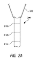
ここで図2A~図2Cを参照すると、靴に利用することができる紐ガイド200の実施形態が示されている。紐ガイド200は、より摩擦の少ない内面またはライナなどを利用することなどによって、本明細書に記載されたもののいずれかと同様であり得る。図2Aに示すように、紐ガイド200は細長い本体を含む。細長い本体は、前述のように設計された伸張を有することができる。いくつかの実施形態では、設計された伸張は、紐202の近くでより柔軟であるかまたはより剛性であることなどによって、ガイド200の長手方向の長さに沿って変化し得る。
[0084]
Here, with reference to FIGS. 2A to 2C, an embodiment of the
[0085]
紐ガイド200は、設計された効果を達成するためにその長手方向の長さに沿って靴に取り付けられるように設計されている。例えば、紐ガイド200は、紐202の近くにある第1の点212a、靴のソールの近くにある第2の点212c、および/または第1の点212aと第2の点212cとの間に位置決めされる第3の点212bにおいて靴に取り付けることができる。これらまたは他の様々な点において紐ガイド200を取り付けることは、図3A~図3Bでさらに説明されるように、紐ガイド200が靴内でどのように機能するかに影響を及ぼす。図2Bは、紐ガイド200の本体が靴のアッパー210の下に配置され、かつ、紐ガイド200の遠位端がアッパー210のスリットまたは開口214を通って突出するように、紐ガイド200が靴と結合され得ることを示す。図2Cは、複数の紐ガイド200を図2Bに示す方法で靴に取り付けることができることを示す。この構成は、紐ガイド200の大部分が視界から隠蔽されたままであるように利用され得る。
[0085]
The
[0086]
ここで図3A~図3Bを参照すると、靴のアッパー210に取り付けられた紐ガイド200が示されている。図3Bは、アッパー210の内面と、紐ガイド200をアッパー210の内面に取り付けることができる様々な点とを示す。具体的には、図3Bは、前述のように、第1の結合点212a、第2の結合点212c、および第3の結合点212bを示す。様々な点のうちの1つにおいて紐ガイド200を結合することは、紐ガイド200がどのように機能するかに影響を及ぼす。例えば、紐ガイドが第1の結合点212aにおいてアッパー210に取り付けられている場合、紐ガイド200の弾性伸張は減少し、および/または、アッパー210に対する紐ガイド200の力は靴の舌革のより近くで加えられる。対照的に、紐ガイド200が第2の紐結合点212bにおいてアッパー210に取り付けられている場合、紐ガイド200の弾性伸張は著しく大きくなり、および/または、アッパー210に対する紐ガイド200の力は靴のソールのより近くで加えられる。
[0086]
Here, referring to FIGS. 3A to 3B, the
[0087]
図2Bの図解とは異なり、紐ガイド200は、図3A~図3Bにおいては、アッパー210の下に全体が配置されているものとして示されている。この構成では、紐202は紐ガイド200からアッパー210のスリット214を通って延伸する。図3A~図3Bの構成は、紐ガイド200が視界から完全に隠蔽されていることを保証する。これは視覚的に魅力的であるかまたは一部のユーザの間で所望され得る。
[0087]
Unlike the illustration in FIG. 2B, the
[0088]
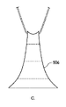
図5は、靴のような物品の所望の与張を達成するために利用され得る様々な紐ガイド構成を示す図である。例えば、最小の取り付けスペースが利用可能であるとき、かつ/または紐ガイドの伸張がほとんどまたはまったくないことが所望されるとき、比較的短い紐ガイド502を利用することができる。他の実施形態では、相当により大きい伸張が所望されるとき、かつ/または靴の長さに沿って閉じる力を分散させることが望ましいときは、細長い紐ガイド504を利用することができる。他の実施形態では、上側部分と比較してより広い底部分を有する紐ガイド506を利用することができる。この紐ガイド506は、閉じる力を靴の周り、特にガイド506の底部分の周りで横方向に分散させることが望ましい場合に利用することができる。さらに他の実施形態では、紐ガイド508は、上部区画または底部区画のいずれよりも広い中間区画を有する逆砂時計構成を有してもよい。この構成は、靴の中間部分を与張することが所望されるときに利用され得る。
[0088]
FIG. 5 is a diagram showing various lace guide configurations that can be used to achieve the desired tension of an article such as a shoe. For example, a relatively
[0089]
ここで図10A~図10Cを参照すると、靴のような物品に容易かつ迅速に取り付けられるように構成され、かつ張力部材または紐を物品の経路の周りで方向付けるかまたは送るように構成されている張力部材ガイドまたは紐ガイド1000(以下、紐ガイド1000)の一実施形態が示されている。紐ガイド1000は、第1の材料部材または内側部材1004(以下、内側部材1004)、第2の材料部材または中間部材1006(以下、中間部材1006)、および第3の材料部材または外側部材1002(以下、外側部材1002)を含む。内側部材1004は、長手方向の長さ、横方向の幅、物品に対して位置決め可能な第1の面、および第1の面とは反対側の第2の面を含む。中間部材1006は、典型的には、外側部材1002と内側部材1004との間に位置決めされ、それらに結合されるが、いくつかの実施形態では、外側部材1002は省略されてもよい。中間部材1006は、紐(図示せず)と接触し、紐を物品の経路に沿って案内または送る紐ガイド1000の構成要素として機能する。中間部材1006は、紐に動作可能に接触または係合するため、中間部材1006は、典型的には、外側部材1002および内側部材1004と比較して、摩擦が少ない材料から作製される。
[0089]
Referring here to FIGS. 10A-10C, it is configured to be easily and quickly attached to an article such as a shoe, and to direct or feed a tension member or lace around the path of the article. An embodiment of a tension member guide or a string guide 1000 (hereinafter referred to as a string guide 1000) is shown. The
[0090]
いくつかの実施形態では、中間部材1006は、図4Aに示す構成と同様に、外側材料層と内側材料層とを備える。外側材料層は、内側材料層を補強または構造的に支持するために、内側材料層よりも硬いまたは剛性の材料であり得る。内側材料層は、紐と係合して直接紐と接触する低摩擦材料であり得る。例示的実施形態では、外側材料層はナイロン材料とすることができ、内側材料層はテフロン(登録商標)材料とすることができる。他の実施形態では、中間部材1006は、低摩擦であるとともに構造的に強固な単一材料層であり得る。例えば、中間部材1006はナイロン/テフロン(登録商標)混合材料層であってもよい。
[0090]
In some embodiments, the
[0091]
任意の実施形態において、中間部材1006は、外側部材1002と内側部材1004との間に挟まれてそれらに結合されている。中間部材1006は、長手方向の長さに沿って折り返されて、中に紐が挿入され得るループまたはチャネルを形成する。ループ状中間部材1006は、中間部分と、横幅に沿った2つの端部部分とを有し、2つの端部部分は図示のように中央部分の対向する両側に配置されている。外側部材1002および内側部材1004と結合されたとき、中間部材1006は、図示のように長手方向において外側部材および内側部材よりも短い。この構成は、紐ガイド1000の近位端を紐ガイド1000の遠位端よりも薄くすることを可能にする。具体的には、図10Cは、紐ガイド1000の側面プロファイルを示し、紐ガイド1000の近位端が、紐ガイド1000の遠位端の厚さT2よりも相当に薄い厚さT1を有することを示す。中間部材1006は、図示のように中間部材1006の対向する両端部が互いにずれているように、外側部材1002と内側部材1004との間に位置決めされてもよい。この構成は、より厚い遠位端T2とより薄い近位端T1との間の急激な遷移ではなく、漸進的な遷移をもたらす。図示のように、中間部材1006が内側部材1004と結合されると、中間部材1006は内側部材1004と長手方向に位置整合され、内側部材1004の第2の面の上に位置決めされる。
[0091]
In any embodiment, the
[0092]
図10Bは、紐ガイド1000の組み立てられた構成要素を示す。図示のように、外側部材1002および内側部材1004は、通常、中間部材1006の上部またはループ状端部が露出されたままであるように、中間部材1006を越えて延伸せず、またはその上に折り返されない。この構成では、紐に直接接触して紐を案内する/送る紐ガイド1000の構成要素である中間部材1006は、外側部材1002および内側部材1004によって妨げられ得ない。したがって、紐が与張されているとき、中間部材1006は、紐に対して自由に撓曲、屈曲、調整、または適合することができる。そのような実施形態では、外側部材1002および内側部材1004は、主に中間部材1006を補強するために、および/または中間部材1006を物品に取り付けるために使用され得る。いくつかの例では、中間部材1006は、縫合1008を介して形成された結合線に沿って内側部材1004から外側に旋回可能であり得る。他の実施形態では、外側部材1002および内側部材1004は、所望に応じて、中間部材1006を部分的にまたは完全に被覆して延伸することができる。いくつかの実施形態では、外側部材1002の上端部は、中間部材1006の上部またはループ状端部の近位に位置決めされてもよい。内側部材1004の上端部は、中間部材1006の上部またはループ状端部と実質的に同じ高さであり得る。
[0092]
FIG. 10B shows the assembled components of the
[0093]
紐ガイド1000はいくつかの構成要素から作製されているため、縫合1008を使用して最初に様々な構成要素をともに取り付けることができる。縫合1008は、外側部材1002および内側部材1004を通して、ならびに中間部材1006の近位部分を通して挿入されてもよい。他の実施形態では、様々な部材は、最初に、溶接(熱、RF、音波など)、接着剤接合、機械的締結、またはその他の既知の方法によって結合されてもよい。外側部材1002および内側部材1004の近位端は、縫合、溶接、接合などによって同様に取り付けることができる。
[0093]
Since the
[0094]
内側部材1004の内面1010は、物品と容易かつ迅速に結合するように構成されている。例えば、内側部材1004の内面1010は、内側部材1004が熱溶接、音波溶接、接着剤接合などを介して物品に迅速に付着することを可能にする接着剤層を含むことができる。特定の実施形態では、紐ガイド1000は、内側部材1004の内面1010をアッパーの内面に対して位置決めし、2つの内面をともに溶接することによって靴のアッパー(図示せず)の内面に取り付けることができる。具体的には、内面1010は、ガイド1000を物品の表面に熱溶接することを可能にするTPU材料を含み得る。
[0094]
The
[0095]
紐ガイド1000は、物品の周りで紐を送るまたは案内するための経路を形成するために物品に迅速かつ容易に取り付けることができる単一の構成要素である。いくつかの実施形態では、中間部材1006は、本明細書に記載されるように紐張力をより均一に分散させるように構成されてもよい。
[0095]
The
[0096]
紐ガイド1000を物品と結合する方法は、上述のような構成を有する紐ガイド1000を提供することと、紐ガイド1000を物品と結合することとを含む。この方法はまた、通常、中間部材1006に形成されたループまたはチャネルを通して張力部材を挿入することを含む。紐ガイド1000を物品と結合することは、内側部材1004を物品に熱溶接することを含み得る。
[0096]
The method of connecting the
[0097]
ここで図11A~図11Cを参照すると、設計された撓曲または伸張を呈する張力部材ガイドまたは紐ガイド1100(以下、紐ガイド1100)の一実施形態が示されている。紐ガイド1100は、張力部材または紐を物品の経路の周りで方向付けるかまたは送るように構成される。紐ガイド1100の設計された撓曲は、紐ガイド1100の本体に形成されている個々のチャネルまたは穴1102を介して形成される。個々のチャネルまたは穴1102は、紐ガイド1100の材料本体の近位端と遠位端との間に延伸する。紐ガイド1100は、材料本体内に個々のチャネルまたは穴1102を形成するように織られている。横糸または生地のより糸は生地本体に壁1104を形成し、これが個々のチャネル1102の各々を分離している。図11A~図11Cは、8つの別個のチャネル、すなわちチャネル1102a~1102hを有する紐ガイド1100を示すが、より多くのまたはより少ないチャネル1102を所望に応じて形成することができることを理解されたい。
[0097]
Here, with reference to FIGS. 11A-11C, an embodiment of a designed flexure or extension tension member guide or string guide 1100 (hereinafter, string guide 1100) is shown. The
[0098]
図11Cに示すように、紐ガイド1100の材料本体は近位端と遠位端との間で折り返されて、中に張力部材または紐1110(以下、紐1110)が挿入され得るループまたはチャネルを形成する。材料本体のループ状端部は、中央部分と、図示のように中央部分の対向する両側に配置された対向する両端部または端部部分とを有する。紐ガイド1100は、紐ガイド1100の中央部分と比較して、対向する両端部に向かってまたは両端部においてより高い可撓性を有するように構成される。この構成は、紐が与張されるときに紐ガイド1100が湾曲して紐1110に適合することを可能にし、その結果として、紐ガイド1100の横幅にわたって紐張力がより均一に分散される。
[0098]
As shown in FIG. 11C, the material body of the
[0099]
対向する両端部の可撓性の増加は、紐ガイドの材料本体の少なくとも1つのチャネル1102、より一般的には様々なチャネル1102内に補強材料(例えば、繊維)を詰め込むか配置することによって達成される。補強材料は、補強が中に配置されている紐ガイド1100のチャネル1102を補強するように機能する。図11Bは、繊維または繊維束1106が様々な程度で紐ガイドのチャネル1102の一部または全部の中に挿入されていることを示している。個々のチャネル1102の剛性は、チャネル内に挿入される繊維1106の数、すなわちチャネル内の繊維密度が増加するにつれて増加する。言い換えると、より多くの繊維1106がチャネル内に配置されるにつれて、個々のチャネルの可撓性が低下する。これは、挿入された繊維がそれぞれのチャネルを補強するように機能し、それによってそれぞれのチャネルの剛性が増し、可撓性が減少することに起因する。図11Bに示されるように、紐ガイド1100は、中央チャネル(すなわちチャネル1102dおよび1102e)が最大密度の繊維1106(すなわち、チャネルとともに配置された最も多い繊維1106)を有するように形成されてもよい。中央チャネルに直に隣接する2つのチャネル(すなわち、チャネル1102cおよび1102f)はわずかに低い繊維密度を有することができ、次の2つの直に隣接するチャネル(すなわちチャネル1102bおよび1102g)はさらに低い繊維密度を有することができる。2つの外側チャネル(すなわち、チャネル1102aおよび1102g)は、全チャネルのうちで最も低い繊維密度を有することができる。このようにして、個々のチャネルの繊維密度は、紐ガイド1100の中央部分から横方向に漸進的に減少し得る。結果として、紐1110が与張されると、紐ガイド1100は、設計された方法で紐ガイド1100の中央部分から横方向外側に撓曲し、適合することができる。設計された撓曲または湾曲は、紐ガイド1100にわたって横方向に紐張力を均一に分散させるように設計することができ、これによってガイド上の紐の摩耗が大幅に低減し得る。
[0099]
Increased flexibility at the opposing ends is achieved by packing or placing a reinforcing material (eg, fiber) within at least one channel 1102, more generally various channels 1102, of the material body of the string guide. Will be done. The reinforcing material functions to reinforce the channel 1102 of the
[0100]
繊維1106は、通常、紐ガイド1100の製織中または形成中にチャネル1102内に位置決めされる。図11Aは、紐ガイド1100内に位置決めされ得る繊維の代表的な実施形態を示す。具体的には、図11Aは、4つの繊維または繊維束が2つの中央チャネル(1102dおよび1102e)内に位置決めされ得、3つの繊維/繊維束が直に隣接するチャネル(1102cおよび1102f)内に位置決めされ得、2つの繊維が次の横方向に隣接するチャネル(1102bおよび1102g)内に位置決めされ得、2つの横方向において最も外側のチャネル(1102aおよび1102h)はいかなる繊維も含まれ得ないことを示す。図11Aの実施形態は例示のみを目的とし、紐ガイド1100をいかなる特定の構成に限定することも意図しない。むしろ、当業者が認識するように、紐与張に応答してガイドの所望の撓曲または湾曲を達成するために、チャネル配置および繊維密度を所望に応じて変化させることができる。
[0100]
The
[0101]
紐ガイド1100の中央部分に向かって繊維密度を増加させることはまた、ガイドの中央に向かって紐ガイド1100が集まるのを防ぐのを助ける。例えば、中央チャネルはより多くの繊維を「詰め込まれている」ため、これらのチャネルは、張力下で紐1110によって紐ガイド1100に及ぼされる内向きの圧縮力に、より容易に抵抗することができる。個々のチャネル1102a~1102h内の繊維密度は、内向きの圧縮力を打ち消すように、および/または所望に応じてガイドの湾曲もしくは撓曲をもたらすように設計することができる。ガイド1100が集まることが低減すること、および/または設計された撓曲/湾曲によって、ガイド1100にわたって横方向に均一な張力または負荷を維持するのを助けることができる。
[0101]
Increasing the fiber density towards the central portion of the
[0102]
いくつかの事例では、紐ガイド1100の内面は、紐1110と紐ガイド1100との摩擦係合を低減する低摩擦材料を含み得る。例えば、紐ガイド1100の内面は、低摩擦材料がガイド1100のループ状端部内に位置決めされている図4A~図4Cと同様の構成を有することができる。
[0102]
In some cases, the inner surface of the
[0103]
紐ガイド1100を物品と結合する方法は、本明細書において説明されているような構成を有する紐ガイド1100を提供することと、紐ガイド1100を物品と結合することとを含む。方法はまた、通常、紐ガイド1100の折り返された材料本体に形成されたループまたはチャネル内に紐1110を挿入することをも含む。
[0103]
The method of binding the
[0104]
ここで図12を参照すると、紐ガイドが靴などの物品に迅速かつ容易に取り付けられることを可能にする構成要素1200の一実施形態が示されている。構成要素1200は、取り付け部材1202およびガイド部材1210を含む。ガイド部材1210は折り返されてループ1212を形成し、それを通して紐または張力部材(図示せず)が挿入される。ガイド部材1210の対向する両端部は、縫合1214、接着剤接合、溶接(例えば、RF、熱、音波など)を介して、またはその他の取り付け方法を介して取り付け部材1202に取り付けられる。取り付け部材の内面1204は、取り付け部材1202を物品と結合するのを助ける材料を含む。例えば、取り付け部材1202の内面1204は、TPUまたは取り付け部材1202を物品に熱溶接するのを助ける別の材料を含み得る。内面1204は同様に、構成要素1200を物品と結合するのを助ける感圧および/または感熱材料を含み得る。
[0104]
Here, with reference to FIG. 12, an embodiment of the
[0105]
取り付け部材1202は、より大きい表面積にわたってガイド部材1210に加えられる任意の力または負荷を分散させるより大きい表面積を提供し、これによって、構成要素1200が物品から外れないことを保証することが助けられる。いくつかの実施形態では、内面1204の反対側の面(すなわち、外面)が取り付け材料を含む。そのような実施形態では、内面1204は取り付け材料を含まなくてもよい。構成要素1200は、物品の周りで個々に位置決めされ、それと結合されて物品の周りで紐経路を形成することができる別個の個別のユニットとして製造することができる。
[0105]
The mounting
[0106]
図13A~図Cは、構成要素1200を靴などの物品に取り付ける様々な実施形態を示す。図13Aは、構成要素1200が物品1300に取り付けられている一実施形態を示す。物品1300は、それを通して紐1304が挿入される一対の紐ポート1302を含む。構成要素1200は、物品の外部から見えないように物品1300の内面に位置決めされる。取り付け構成要素1202の内面1204は、ガイド部材1210が物品1300の内面と取り付け部材1202の内面1204との間に挟まれるように、物品1300の内面と結合されている。他の実施形態では、ガイド部材1210が物品1300の内面に接触しないように、取り付け部材1202の外面(番号なし)を物品の内面に取り付けることができる。
[0106]
13A-C show various embodiments in which the
[0107]
構成要素1200は、ループ状端部または縁部1220が物品1300の縁部1310から引っ込むように物品1300の周りで位置決めされる。理想的には、ループ縁部1220は、与張されたときに、紐1304の自然な湾曲によって、紐1304が図示のように紐ポート1302を通ってほぼ中央に位置決めされるように位置決めされる。このように構成要素1200を位置決めすると、紐1304と紐ポート1302との摩擦係合が減少する。具体的には、この構成は、紐1304が紐ポート1302の上縁、下縁、または側縁と擦れ合うことを低減または防止する。
[0107]
The
[0108]
図13Bは、ループ縁部1220が紐ポート1302により近いように物品1300内に位置決めされた構成要素1200を示す。具体的には、ループ縁部1220は、紐ポート1302の中心線1306に隣接するように位置決めされる。ループ縁部1220は、中心線1306から距離X1だけオフセットすることができ、この距離は紐ポート1302の半径より小さくてもよい。他の実施形態では、ループ縁部1220は、紐ポート1302の中心線1306と実質的に一致してもよい。いくつかの実施形態では、ガイド部材1210の縁部またはコーナは、紐ポート1302を通して見えてもよい。いずれの実施形態でも、構成要素1200は、紐1304が与張されたときに紐1304が紐ポート1302内のほぼ中央に位置決めされるように、物品1300内に位置決めされるべきである。図13Bの構成は、紐1304が非常に可撓性または屈曲可能であるときに特に有用であり得る。
[0108]
FIG. 13B shows a
[0109]
図13Cは、ループ縁部1220が紐ポート1302の中心線1306から大きくオフセットされるように、構成要素1200が物品1300内に配置されている実施形態を示す。ループ縁部1220は、中心線1306から距離X2だけオフセットされており、この距離は、構成要素が紐ポート1302から遠く離れるほど十分に大きい。前述の実施形態と同様に、構成要素1200は、理想的には、与張されたときに紐1304が紐ポート1302を通じてほぼ中央に位置決めされるように位置決めされる。図13Cの構成は、可撓性がより少なく、したがって、ガイド部材1210を通じて撓曲、屈曲、または湾曲するためにより大きい距離を必要とする紐に特に有用であり得る。
[0109]
FIG. 13C shows an embodiment in which the
[0110]
図13Dは、構成要素1200が靴の外側から見えないように、靴1350の内面に位置決めされた取り付け構成要素1200を示す。構成要素1200の内面1204は、ガイド部材1210が靴1350の内面と取り付け構成要素1200の内面1204との間に挟まれるように、靴1350の内面と結合され得る。靴1350は、靴1350の周りの経路に沿って位置決めされる紐1304を案内するために靴1350の周りに配置された複数の取り付け構成要素1200を含む。図13Dは、ループ縁部1220が紐ポート1302の中心線の近くに位置決めされている与張状態の紐1304を示している。この状態では、紐1304は、紐1304と紐ポート1302との摩擦係合が最小になるように、紐ポート1302を通じてほぼ中央に位置決めされる。与張されていない状態では、ループ縁部1220は、紐ポート1302の中心線から引っ込んでいてもよい。
[0110]
FIG. 13D shows a
[0111]
ここで図14を参照すると、物品1410内のガイド部材1402の理想的な位置決めが示されている。具体的には、ガイド部材1402は、紐1404が与張されたときにガイド部材1402の遠位縁部1406が紐ポート1412に対してほぼ中心になるように位置決めされる。例えば、紐ポート1412はYの開口幅を有してもよく、ガイド部材1402の遠位縁部1406は物品1410の上側材料に対してほぼY/2に位置決めされてもよい。この構成は、紐が与張されるときに紐1404を紐ポート1412を通ってほぼ中央に位置決めするのを助け、これによって、紐1404と紐ポート1412および物品1410との摩擦接触または係合が減少する。
[0111]
Here, with reference to FIG. 14, the ideal positioning of the
[0112]
ここで図15A~図15Bを参照すると、靴などの物品のメッシュ材料に直接溶接または取り付けることができるガイド構成要素1510の実施形態が示されている。図15Aは、取り付け部材1514に取り付けられているガイド部材1512を含むガイド構成要素1510を示す。取り付け部材は通常、ガイド部材1512よりも大きい表面積を有する。取り付け部材1514は、物品のメッシュ1502に取り付けられ、紐(図示せず)の与張に起因してガイド部材1512に加えられる任意の負荷または力を分散させるのを助ける。他の実施形態と同様に、ガイド部材1512は、紐が挿入されるループを形成するように折り返され、ガイド部材1512は取り付け部材1514に取り付けられる。
[0112]
Here, with reference to FIGS. 15A-15B, embodiments of
[0113]
取り付け部材1514はメッシュ1502に結合されている。取り付け部材1514は、典型的には、メッシュ材料1502に溶接(例えば、熱溶接、音波溶接、RF溶接など)されるが、接着剤接合などのような様々な他の形態の取り付けが可能である。取り付け部材1514がメッシュ1502に溶接されると、溶接領域が形成され、これは図15Aのクロスハッチ区画1520によって示される(以下、溶接領域1520)。溶接は、溶接されていないメッシュ1502と比較して、溶接領域1520を著しくより硬くまたは剛性にする。溶接領域1520は、メッシュ1502の非伸張領域または部分を画定し、これは、本明細書で以下に記載されるように物品を与張するかまたは締め付けるために利用され得る。
[0113]
The mounting
[0114]
図15Bは、ガイド構成要素1510の異なる実施形態を示す。ガイド構成要素1510は、ガイド構成要素1510が取り付け部材(すなわち、1514)を含まないことを除いて、図15Aに示すものと同様である。そうではなく、ガイド構成要素は、メッシュ1502に直接結合されているガイド部材1512のみを含む。例示的な実施形態では、ガイド部材1512は溶接によってメッシュ1502に結合され、これによって、非伸縮性であり、所望の方法で物品のフィットまたは締め付けに影響を及ぼすために使用することができる溶接領域1520が形成される。図15Bはまた、ガイド部材1512のループ状端部がスリットまたは開口部1506を通って位置決めされ得、それによって、ループ状端部がガイド部材1512の残りの部分からメッシュ1502の反対側にあることを示す。
[0114]
FIG. 15B shows different embodiments of the
[0115]
ここで図16A~図16Eを参照すると、溶接領域1520を利用して所望の方法でメッシュ1502を締め付けまたは与張する実施形態が示されている。溶接領域1520が紐によって与張されると、溶接領域1520はメッシュ1502に影響を及ぼすと考えられる。具体的には、張力が溶接領域1520に加えられると、加えられる力と反対側に位置するメッシュ1502の領域または部分は、歪みまたは伸張され、一方、溶接領域1520および加えられる力に横方向に隣接して位置するメッシュ1502の部分は、歪まずまたは伸張されない。このように、溶接領域1520が与張されると、張力の大部分は、加えられる力とは反対側に位置するメッシュに伝達され、横方向に隣接するメッシュ1502には加えられない。この効果は、固有の方法で靴を与張するために利用することができる。
[0115]
Here, with reference to FIGS. 16A to 16E, embodiments are shown in which the
[0116]
図16Aは、靴などの物品のメッシュ1502に溶接されているガイド構成要素1510を示している。溶接領域1610は、細長いUの形状でメッシュ1502上に形成される。溶接領域1610は、メッシュ1502がともに溶接されていない細長いUの対向する両側の間に隔離ゾーンまたは領域1612を形成する。溶接領域1610は、メッシュ1502の底部まで延伸してもよく、または所望に応じてそこから近位に終端してもよい。ガイド部材1510が与張されると、溶接領域1610が隔離ゾーン1612の与張および/または伸張を引き起こすと考えられる。溶接領域1610の横方向外側に位置するメッシュ1502の部分は、隔離ゾーン1612よりも著しく小さい与張または伸張を経験し、したがって、溶接領域1610は、メッシュ1502を与張可能部分と与張不能部分とに分割する分割部材と同様に機能する。そのような実施形態では、紐が与張されるとき、溶接領域1610および隔離ゾーン1612は独立したパネルと同様に機能する。
[0116]
FIG. 16A shows a
[0117]
図16Bは、ガイド構成要素1510が、溶接領域1520を形成する溶接を介してメッシュ1502に溶接されている別の実施形態を示す。溶接領域1520は、ガイド部材1510と大きさおよび形状が類似している。図16Cに示すように、紐1622を介したガイド構成要素1510の与張は、溶接領域1520のすぐ反対側に位置するメッシュ1502のゾーンまたは部分1620を与張する。図16Dは、V字状溶接領域1630を画定するようにメッシュ1502に溶接されているガイド構成要素1510のさらに別の実施形態を示す。図16Eに示すように、紐1622を介したガイド構成要素1510の与張は、溶接領域1630のすぐ反対側に位置するメッシュのゾーンまたは部分1620を与張すると考えられる。与張ゾーンまたは部分1620は、溶接領域1630の対向する両端部またはアームからメッシュを通じて下向きに延伸することができる。与張ゾーンまたは部分1620の外側に位置決めされているメッシュ材料1502は、与張ゾーンまたは部分1620内に位置決めされているメッシュ1502よりも大幅に小さく与張または伸張され得る。したがって、溶接領域1630を利用して、メッシュ材料1502を所望の方法で固有に与張することができる。
[0117]
FIG. 16B shows another embodiment in which the
[0118]
図16A~図16Eの構成は例示に過ぎず、この概念をいずれか1つの特定の構成に限定するように意図するものではないことを理解されたい。むしろ、当業者であれば、メッシュ材料に所望の方法で与張するために他の様々な溶接領域構成を形成することができることを容易に認識するであろう。言い換えれば、メッシュ1502は、ガイド部材1510を取り付けるときに所望の溶接領域1520を形成することによって固有に与張することができ、これによって、メッシュ1502の所望の部分が選択的に与張される。
[0118]
It should be understood that the configurations of FIGS. 16A-16E are merely exemplary and are not intended to limit this concept to any one particular configuration. Rather, one of ordinary skill in the art will readily recognize that various other weld zone configurations can be formed to tension the mesh material in the desired manner. In other words, the
[0119]
図17は、靴1700のメッシュ材料1704と結合されたいくつかのガイド構成要素1510を示す。具体的には、2つのガイド構成要素1510が靴1700の片側と結合しているように示されている。各ガイド構成要素1510はメッシュ1704に溶接されて、前述のように隔離領域1712を画定する細長いU字状溶接領域1710を形成する。図17の構成は、各隔離ゾーン1712の比較的独立した与張または伸張をもたらし、それは、足を取り巻き、かつその周りでよりぴったりとフィットするようにメッシュ1704を引っ張るかまたは巻き付ける。隔離ゾーン1712は、機能的には、ユーザの足を取り巻いて緊密に引っ張られるであろう独立したストラップと同様であり得る。
[0119]
FIG. 17 shows
[0120]
各ガイド構成要素1510は、張力部材または紐1702と動作可能に結合され、張力部材または紐1702は、リール式締め付け機構1706と動作的に結合される。締め付け機構1706の動作(すなわち、ノブ構成要素の回転巻き)は、紐1702が与張されるようにし、これによって、ガイド構成要素1510および隔離ゾーン1712内のメッシュ材料1502の各々が与張される。
[0120]
Each
[0121]
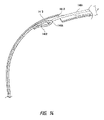
ここで図18A~図18Cを参照すると、2つの材料層の間にガイド部材1802を結合することによって形成されたガイド構成要素1810の一実施形態が示されている。ガイド部材1802は、それを通して紐が挿入される穴を有する管区画である。ガイド部材は、上側材料層1804と下側材料層1806との間に位置決めされている。ガイド部材1802は、通常、所望の半径または曲率に沿って紐を案内または送るように屈曲または湾曲している。特定の実施形態では、ガイド部材1802は織物シース材料から形成されてもよい。
[0121]
Here, with reference to FIGS. 18A-18C, one embodiment of a
[0122]
上側材料層1804は、ガイド部材1802がそれらの間に固定的に位置決めされるように下側材料層1806に取り付けられる。上側材料層1804と下側材料層1806とは、接着剤接合、縫合などを介してともに結合されてもよい。例示的な実施形態では、上側材料層1804と下側材料層1806とは溶接(例えば、熱、音波、RFなど)を介して結合される。形成されると、ガイド構成要素1810は、紐経路を形成し、紐経路に沿って張力部材または紐を案内または送るために、靴などの物品に取り付けることができる。
[0122]
The
[0123]
図19は、靴1900に取り付けられた図18A~図18Cの複数のガイド構成要素1810を示す。ガイド構成要素1810は、靴1900の舌革の周りで紐経路を形成する。紐1902は、ガイド構成要素1810を介して紐経路に沿って送られまたは案内される。紐1902は、締め付け機構1904が操作されたときに紐1902を与張するようにリール式締め付け機構1904と動作可能に結合されている。
[0123]
FIG. 19 shows a plurality of
[0124]
ここで図20A~図20Dを参照すると、靴のアッパーと舌革との間などの靴の部分間の遷移をもたらし、および/または、遷移構成要素2000の下に位置するガイドを隠しもしくは隠蔽するために、靴または物品に取り付けることができる遷移構成要素2000の実施形態が示されている。遷移構成要素2000は、アッパー2002の遠位縁部付近で靴のアッパー2002に取り付けられた近位部分2004を含む。遷移構成要素2000の近位端2004は、縫合2003、接着結合、溶接、またはその他の方法でアッパー2002と結合することができる。いくつかの実施形態では、近位端2004は、アッパー2002との結合点においてまたはその付近で折り返されてもよい。
[0124]
Referring here to FIGS. 20A-20D, it results in a transition between parts of the shoe, such as between the shoe upper and the tongue leather, and / or hides or hides a guide located under the
[0125]
遷移構成要素2000はまた、アッパー2002の反対側に位置決めされた遠位端2020も含む。遷移構成要素2000は、近位端2004と遠位端2020との間で折り返され得る(2010)(以後、折り返し端部2010)。いくつかの実施形態では、折り返し端部2010は、縫合2012、接着剤接合、溶接などを介してともに結合されてもよい。遠位端2020は、アッパー2002の下に位置決めされてそれに結合された紐ガイド2006を部分的にまたは完全に被覆するように、アッパー2002の下に位置決めされる。縫合2012、または他の結合は、遠位端2020をアッパー2002の下かつ紐ガイド2006の上の位置に維持するのを助けることができる。紐ガイド2006は、それを通して紐または張力部材が挿入されるループ状端部2008を含む。いくつかの実施形態では、遷移構成要素2000の遠位端2020は、遠位端2020がアッパー2002の下で自由に浮遊するように、アッパー2002から切り離されているかまたは取り付けられていない。
[0125]
The
[0126]
図20Bは、アッパー2002に結合された遷移構成要素2000の斜視図を示す。図20Bは、ガイド部材2006のループ状端部2008を通じて位置決めされた紐2030を示す。図20Cは、遷移構成要素2000の底面斜視図を示す。図示のように、遷移構成要素2000は、折り返し端部2010の近くに位置決めされた紐ポート2022を含む。紐2030は、遷移構成要素2000の下に位置決めされたガイド部材2006にアクセスできるように、紐ポート2022を通して挿入される。
[0126]
FIG. 20B shows a perspective view of the
[0127]
図20Dは、靴2040と結合された遷移構成要素2000を示す。遷移構成要素2000は、靴の対向するアッパーと結合されており、靴の対向するアイステイに沿って横切るように位置決めされている。詳細図に示されるように、遷移構成要素2000の遠位端2020は、ガイド部材2006と靴の舌革2042との間に位置決めされる。遷移構成要素2000は、遷移構成要素2000の下に位置するガイド部材2006を隠蔽しまたは隠す。ガイド部材2006の隠蔽は、円滑な、継ぎ目のない、均一の、またはその他の様態で魅力的な見かけまたは外観をアッパーに提供し得る。遷移構成要素2000はまた、ガイド部材2006と舌革2042との間の比較的円滑な遷移を提供し得、それによって紐2030と舌革2042との間の摩擦係合を減少させ、および/またはこれらの構成要素間の摩耗を減少させる。
[0127]
FIG. 20D shows the
[0128]
遷移は、紐2030が、ガイド部材2006から舌革2042への急激な遷移を経るのではなく、遷移構成要素2000内で紐ポート2022から外へ送られることによって達成される。遷移構成要素2000は、ガイド部材2006と舌革2042との間の円滑な遷移をさらにもたらすために低摩擦材料から作製されてもよい。遷移構成要素2000はまた、ガイド部材2006を視界から隠し、それによって、所望され得るアッパーのなめらかな外観を提供し得る。図20A~図20Dの遷移構成要素2000は、ガイド部材2006のループ状端部が、舌革2042とアッパー2002の内面との間に紐が挟まれ得るアイステイ縁部の内側に位置決めされる場合に特に有用である。
[0128]
The transition is achieved by the
[0129]
ここで図21A~図21Bを参照すると、遷移構成要素2100の別の実施形態が示されている。遷移構成要素2100は、遷移構成要素2100が近位端2004および遠位端2020を含むという点で、図20A~図20Dに示されたものと同様である。近位端2004は、前述のようにアッパー2002に結合されている。遷移構成要素2100はまた、紐2030が送られる紐ポート2022を含む。図20A~図20Dの遷移構成要素2000とは異なり、図21A~図21Bの遷移構成要素2100は折り返し端部2010を含まない。そうではなく、遠位端2020は、アッパー2002から横方向外側に延伸している。靴(図示せず)に取り付けられると、遷移構成要素2100の遠位端2020は靴の舌革の上に位置することになる。紐2030は、ガイド部材2006にアクセスするために遷移構成要素2100の上を摺動して紐ポート2022に入る。ガイド部材2006は、図示のようにアッパー2002の下に位置決めすることができ、または所望に応じてアッパー2002の上に位置決めされてもよい。図21A~図21Bの遷移構成要素2100は、ガイド部材2006のループ状端部がアイステイ縁部にまたはその近くに位置決めされている場合に特に有用である。
[0129]
Here, with reference to FIGS. 21A-21B, another embodiment of the
[0130]
ここで図22A~図22Cを参照すると、ガイド部材を隠蔽しまたは隠すために、および/または靴の部分間の比較的円滑な遷移を提供するために使用され得る別の遷移構成要素2200が示されている。図22Aに示されるように、遷移構成要素2200は、遷移構成要素2200が近位端2004と、遠位端2020と、近位端2004および遠位端2020の間に位置決めされる折り返しまたはループ状端部2010とを含むという点で、図20A~図20Dの遷移構成要素2000と同様である。近位端2004および遠位端2020は両方とも、ガイド部材2006が遷移構成要素2200内に完全に囲まれるように、アッパー2002に取り付けられている。折り返し端部2010は縫合またはその他の様態でともに結合されていなくてもよい。遠位端2020はアッパー2002の内面と結合され、したがって結合された折り返し端部2010によって定位置に保持または維持される必要がないため、折り返し端部2010の縫合または結合は不要であり得る。遠位端2020は、縫合2021、接着剤接合、溶接などを介してアッパー2002の内面に取り付けることができる。いくつかの事例では、結合2005が、アッパーの縁部付近でアッパー2002に近位端2004を取り付けることができる。
[0130]
Referring now to FIGS. 22A-22C, another
[0131]
図22Bは、遷移構成要素2200の斜視図を示す。図22Bは、紐ポート2015が遷移構成要素2200の折り返し端部2010に形成されていることを示している。紐ポート2015は、ガイド部材2006へのより直接的なまたは直線的なアクセスを提供する。図22Cは、靴に取り付けられた遷移構成要素2200を示す。詳細図は、靴の舌革2042とガイド部材2006との間に位置決めされた遠位端2020を示す。縫合2021、またはその他の方法で結合された遠位端2020は、遠位端2020が舌革2042とガイド部材2006との間に位置決めされたままであることを確実にする。遷移構成要素2200は、ガイド部材2006を隠蔽するかもしくは隠し、および/または舌革2042とガイド部材2006との間の円滑な遷移を提供し、理想的には、ガイド部材2006へのより直接的な紐アクセスを必要とする構成に適し得る。
[0131]
FIG. 22B shows a perspective view of the
[0132]
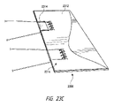
ここで図23A~図23Dを参照すると、紐または張力部材を靴の周りで送るまたは案内するために使用することができる別のガイド部材または構成要素2300が示されている。図23A~図23Bは、ガイド部材2300が、ループ状または折り返し材料ストリップ2304(以下、材料ガイド2304)を材料本体2302の窓または切り取り部分2306内に位置決めすることによって形成されることを示す。窓2306の大きさおよび形状が材料ガイド2304の大きさおよび形状に対応するように、窓2306を材料本体2302内に切り込むことができる。材料ガイド2304の近位端は、縫合2308、接着剤接合、溶接などを介して材料本体2302の内縁と結合されている。いくつかの事例では、材料ガイド2304の近位端は、材料ガイド2304を折り返しまたはループ構成に維持するために一時的な結合2310を有してもよい。材料ガイド2304は、図示のように材料ガイド2304の遠位端が材料本体2302の遠位端と整列するように、窓2306内に位置決めされ、材料本体2302と結合され得る。材料本体2302は、図示のように長手方向において材料本体に沿ってまたはその周りで位置決めされた複数のガイドを含むことができる。材料ガイド2404が材料本体2302の上に位置決めされないので、窓2306内に材料ガイド2304を位置決めすることによって、ガイド部材2300の全体の厚さが減少する。
[0132]
Here, with reference to FIGS. 23A-23D, another guide member or
[0133]
図23Cは、ガイド部材2300および材料ガイド2304の上に位置決めされているカバー材料2312を示している。カバー材料2312は、材料ガイドがカバー材料2312の外部から見えないように材料ガイド2304を隠蔽しまたは隠す。カバー材料2312はまた、材料ガイド2304と材料本体2302との結合を補強し得る。カバー材料2312は、所望に応じてガイドを部分的に被覆してもよく(2314)、またはガイドを完全に被覆してもよい(2316)。
[0133]
FIG. 23C shows the
[0134]
図23Dは、靴2320のアッパーに取り付けられたガイド部材2300を示す。いくつかの例では、靴のアッパーは材料本体2302として機能し、材料ガイド2304はアッパー内に形成された窓2306内に位置決めされる。このとき、カバー材料2312がアッパーおよび材料ガイド2304の上に位置決めされ得、アッパーに取り付けられて材料ガイド2304を被覆し隠すことができる。他の実施形態において、材料本体2302は靴2320の上側材料に取り付けられる。
[0134]
FIG. 23D shows the
[0135]
ガイド部材2300は、ガイド部材2304が靴の舌革にわたる経路に沿って紐2322を案内または送ることができるように、靴2320の対向するアイステイに沿って位置決めされる。個々のガイド部材2304は、ガイド部材2300の上に位置決めされているカバー材料2312を介して視界から隠蔽または隠される。いくつかの事例では、カバー材料2312は靴のアイステイを包み込み、アッパーの外面および内面に取り付けられてもよい。
[0135]
The
[0136]
ここで図24A~図24Bを参照すると、紐を経路の周りで送るまたは案内するために使用され得るガイド部材2400の別の実施形態が示されている。ガイド部材2400は、外側材料本体2402と内側材料本体2406とを含み、それらの間にはループ状または折り返し材料ガイド2404が配置されている。材料ガイド2404は、材料ガイド2404の近位端が内側材料本体2406と外側材料本体2402との間に位置決めされるように、かつ、材料ガイド2404の遠位端が内側材料本体2406内のスロットまたはチャネル2408を通って突出するように、内側材料本体2406に対して位置決めされる。スロット2408を通じた材料ガイド2404の突出部は、紐(図示せず)が材料ガイド2404のループ状端部にアクセスし、当該ループ状端部によって案内また送られることを可能にする。いくつかの実施形態において、材料ガイド2404は、内側材料本体2406と外側材料本体2402とを結合する前に、内側材料本体2406に取り付けられてもよい(2410)。
[0136]
Here, with reference to FIGS. 24A-24B, another embodiment of the
[0137]
材料ガイド2404の遠位端は、図示のように内側材料本体2406の遠位端から引っ込んでいてもよい。この構成は、ガイド部材2400が靴と結合されたときに材料ガイド2404を視界から完全に隠蔽しまたは隠すことを可能にし得る。使用時には、外側材料本体2402が靴のアッパーの内面に位置決めされるように、ガイド部材2400を靴に取り付けることができる。この構成では、内側材料本体2406は靴の内側に面し、材料ガイド2404は外側材料本体2402を介して靴の外側から隠蔽または隠される。いくつかの実施形態において、外側材料本体2402は靴の上側材料であり得、内側材料本体2406および材料ガイド2404はアッパーに直接取り付けられ得る。他の実施形態では、ガイド部材2400は、材料ガイド2404が靴の外側に面し、靴の外側から見えるように配置されてもよい。
[0137]
The distal end of the
[0138]
ここで図25A~図25Dを参照すると、紐ガイドを隠蔽しまたは隠すために、および/または紐ガイドと靴との結合を補強するために、紐ガイドの上に位置決めされ得るカバー部材の実施形態が示される。図25Aは、下側本体2502および上側本体2506を有するカバー部材2500を示す。以下により詳細に説明するように、上側本体2506は、カバー部材2500を紐ガイドの上で靴と結合する際に折り線2508の周りで折り返されるように構成される。いくつかの例では、カバー部材2500は、折り線2508においてカバー部材2500の対向する両側でわずかに切れ込みを入れられてもよい。場合によっては、カバー部材2500の材料は、折り線2508の周りでカバー部材2500を折り返すのを助けるように設計されてもよい。例えば、下側本体2502の周りで上側本体2506を折り返すのを助けるために、材料は、折り線2508に沿ってわずかに薄くされおよび/または折り線を付けられてもよい。下側本体2502は、材料内に一対の切り込み2504を含む。切り込み2504は、弓形または湾曲形状を有し、紐ガイドの対向する両端部がカバー部材2500内から突出することを可能にするように設計されている。
[0138]
Referring now to FIGS. 25A-25D, an embodiment of a cover member that may be positioned on the lace guide to conceal or hide the lace guide and / or to reinforce the bond between the lace guide and the shoe. Is shown. FIG. 25A shows a
[0139]
図25Bは、カバー部材の別の実施形態2500’を示し、カバー部材2500’は、カバー部材2500’が図25Aのカバー部材2500よりも長い横方向長さLを有することを除いて、図25Aのカバー部材2500とほぼ同一の構成を有する。図25Bのカバー部材2500’は、紐ガイドが他の紐ガイドと比較してより長い横方向長さを有する場合に利用することができる。
[0139]
25B shows another embodiment 2500'of the cover member, wherein the cover member 2500'has a lateral length L longer than that of the
[0140]
図25Cは、複数の下側本体部材2522および上側本体部材2526を含むカバー部材2520を示す。カバー部材2520は、同じカバー部材によって複数の紐ガイドを被覆することが所望されるときに利用することができる。前述の実施形態と同様に、図25Cのカバー部材2520は、折り線2528に沿って上側本体部材2526が下側本体部材2522の周りで半分に折り返されるように構成される。カバー部材2520は、折り線2528に沿って両側に刻み目を入れることができ、および/または折り線2528に沿って横方向長さに沿って中間に位置決めされた逃げ切り込み2532を含むことができる。逃げ切り込み2532は、下側本体部材2522の周りで上側本体部材2526を折り返すのを助けることができ、および/またはカバー部材2520内に閉じ込められた汚物および塵芥を逃がすことを可能にすることができる。
[0140]
FIG. 25C shows a
[0141]
いくつかの例では、カバー部材2520は、上側本体部材2526と下側本体部材2522との間に位置決めされ、それぞれの本体部材へと内側に突出する追加の逃げ切り込み2530および/または2531を含み得る。逃げ切り込み2530および/または2531は、閉じ込められた汚物および塵芥がカバー部材2520内から逃げることができる追加の領域を提供することができる。逃げ切り込み2530および/または2531はまた、上側本体部材および下側本体部材を画定し得る。
[0141]
In some examples, the
[0142]
下側本体部材2522は各々、弓状または湾曲形状を有する材料内の一対の切り込み2524を含む。切り込み2524は、紐ガイドの対向する両端部の形状に対応し、紐ガイドの対向する両端部がカバー部材2520から外向きに突出することを可能にするために使用される。下側本体部材2522の切り込み2524は、各切り込みの間に同様の横方向間隔を有してもよく、または、横方向間隔は異なる大きさおよび形状の紐ガイドの使用に適応するように変更されてもよい。同様に、下側本体部材2522および上側本体部材2526は、同様の横方向および/もしくは長手方向の長さ、または可変の横方向および/もしくは長手方向の長さを有してもよい。
[0142]
Each
[0143]
図25Dは、図25Cに示すものと同様の下側本体部材2522を含むが、細長い上側本体部材2542を含むカバー部材2540を示す。細長い上側本体部材2542は、図27Dに示すように靴のアッパーの大部分を被覆することが望ましいときに利用することができる。図示のように、細長い上側本体部材2542の対向する両端部は、所望に応じて異なる大きさおよび/または形状を有することができる。細長い上側本体部材2542の形状および大きさは、靴のアッパーに対応することができ、および/または所望の視覚的外観を提供するように設計することができる。
[0143]
25D shows a
[0144]
ここで図26A~図26Dを参照すると、カバー部材2500を靴のアッパー2602に取り付けるプロセスが示されている。図26Aは、一対のカバー部材2500が最初に広げられた状態で提供されることを示す。カバー部材2500は、対応する紐ガイド2600およびアッパー2602の内面と整列している。紐ガイド2600は、本明細書に記載されるように紐を挿入することができるループ状端部を画定する折り返し材料を含む。図26Bでは、紐ガイド2600は、アッパー2602の内面に対して位置決めされ、縫合、接着剤接合、溶接(例えば、RF、音波など)、機械的締結などを介してそれと結合されている(2610)。図示されるように、紐ガイド2600は、通常、紐ガイド2600の遠位端がアッパー2602の遠位端から引っ込みまたはオフセットされるように、アッパー2602に取り付けられる。
[0144]
Here, referring to FIGS. 26A to 26D, the process of attaching the
[0145]
図26Cでは、カバー部材2500は、紐ガイド2600がアッパー2602とカバー部材2500との間に位置決めされるように、紐ガイド2600およびアッパー2602に隣接して位置決めされている。カバー部材2500は、典型的には、それが紐ガイド2600を完全に被覆するように位置決めされる。次に、紐ガイド2600の対向する両端部2604は、カバー部材2500の下側本体部材2502の一対の切り込み2504を通じて引っ張られるか、またはその他の様態で位置決めされ、それによって対向する両端部2604はカバー部材2500の表面から外向きに突出する。このようにして、紐ガイドの対向する両端部2604、およびそれらの間に配置された紐の穴またはチャネルが露出され、紐にとってアクセス可能となる。切り込み2504の弓形または湾曲形状は、紐ガイド2600の対向する両端部2604が切り込み2504を通じて容易に引っ張られることを可能にする。
[0145]
In FIG. 26C, the
[0146]
図26Dでは、カバー部材2500は、アッパー2602の遠位縁部上で折り線2508に沿って折り返される。その後、カバー部材2500は、紐ガイド2600がカバー部材2500の下に被覆されて隠された状態で、アッパー2602に堅固に取り付けることができる。いくつかの実施形態では、下側本体部材2502を最初にアッパー2602に取り付けることができ、その後、上側本体部材2506をアッパー2602に取り付けることができる。他の実施形態では、上側本体部材2506および下側本体部材2502を同時にアッパー2602に取り付けることができる。カバー部材2500は、下側本体部材2502および紐ガイド2600が靴の内側に位置決めされるように位置決めされてもよく、またはこれらの構成要素が所望に応じて靴の外側に位置決めされるように位置決めされてもよい。
[0146]
In FIG. 26D, the
[0147]
図27A~図27Bは、図23A~図23Bのガイド部材2300を被覆するために利用されるカバー部材2520を示す。図27Aは、材料本体2302の対応する窓2306内に位置決めされた一対の材料ガイド2304を有するガイド部材2300を示す。カバー部材2520は、ガイド部材の材料ガイド2304の位置に対応するように、下側本体部材2522の周りで位置決めされた複数対の切り込み2524を含む。カバー部材2520もまた、ガイド部材2300の形状および大きさに対応する形状および大きさである。前述のように、上側本体部材2526は、折り線2528に沿って下側本体部材2522の周りまたは上に折り重なるように構成される。
[0147]
27A-27B show the
[0148]
図27Bは、ガイド部材2300の上に位置決めされたカバー部材2520を示す。カバー部材2520の上側本体部材2526は、折り線2528の周りで折り返され、ガイド部材2300の反対側に位置決めされる。材料ガイド2304の対向する両側部2305は、対応する対の切り込み2524を通って突出するように位置決めされる。示されるように、材料ガイド2304は、カバー部材2520によって本質的に完全に被覆され、隠蔽され、隠される。
[0148]
FIG. 27B shows a
[0149]
図27Cは、ガイド部材2300の上に位置決めされたカバー部材2520の斜視図を示す。図27Cは、対向する両端部2305が対応する対の切り込み2524を通して挿入されることに起因して材料ガイド2304の対向する両端部2305がアクセス可能性であることを示す。紐は、対向する両端部2305およびそれらの間に配置されたチャネルまたは穴を通して挿入される。対向する両端部2305が一対の切り込み2524を通って挿入されることによって、材料2525のブリッジまたはストリップが材料ガイド2304のループ状端部の上に形成または画定される。カバー部材2520を使用して、材料ガイド2304を被覆して隠し、および/または材料ガイド2304とガイド部材2300の材料本体2302との取り付けを補強することができる。
[0149]
FIG. 27C shows a perspective view of the
[0150]
図27Dは、カバー部材2540が靴の周りに配置された複数の紐ガイドを被覆するように、靴の周りで位置決めされているカバー部材2540を示す。カバー部材2540は、上側本体部材2542が下側本体部材の周りで折り返された状態で示されている。カバー部材2540は、靴のアッパーの内面に位置決めされている複数のガイド2722を被覆する。カバー部材2540はまた、靴のアッパーの外面に位置決めされている1つまたは複数の紐ガイド2720を被覆する。図示のように、カバー部材2540は、内側ガイド2722の対向する両端部のみがカバー部材2540から突出するように内側ガイド2722を被覆してもよい。いくつかの実施形態では、外部ガイド(複数可)2720が、図24A~図24Bに示すものと同様のスロットまたはチャネルを通って突出してもよい。細長い上側本体部材2542は、様々なガイドを隠すことと、靴に均一な見かけまたは外観を提供することの両方のために機能し得る。
[0150]
FIG. 27D shows a
[0151]
図27E~図27Jは、図27A~図27Dに示したものと同様の張力部材ガイド2750の一実施形態を示している。張力部材ガイド2750は、靴または他の履物などの物品と結合可能であり、物品の経路の周りで張力部材を方向付けるかまたは送るように構成される。張力部材ガイド2750は、第1の端部または近位端2751および第2の端部または遠位端2753を含む本体またはカバー部材2752(以下、カバー部材2752)を含む。近位端2751または近位部分は、靴または他の履物などの物品と結合可能であり得る。靴/履物と結合されると、カバー部材2752は通常、図27Jに示すように靴/履物のアイステイに沿って位置決めされる。遠位端2753は、本体の、近位端2751とは反対の側に位置決めされ、いくつかの実施形態では、遠位端2753は、カバー部材2752が折り返される継ぎ目または線を表す。カバー部材2752はまた、カバー部材2752の遠位端2753の近くに位置決めされた一対のスリットまたは切り込み2754を含む。
[0151]
27E-27J show one embodiment of the
[0152]
張力部材ガイド2750はまた、縦方向の長さおよび横方向の幅を有するガイド部材2760を含む。ガイド部材2760は、長手方向長さに沿って折り返されて、中に張力部材2770が挿入されるループまたはチャネル2762を形成する(図27I~図27Jを参照)。折り返されたガイド部材2760は、前述の材料ガイド2304と類似している。ガイド部材2760は、本明細書に記載されているか、またはそうでなければ当該技術分野において既知の任意の材料から作製することができ、典型的には低摩擦材料から作製される。特定の実施形態では、ガイド部材2760は、本明細書の様々な実施形態で説明されているように、低摩擦内側材料と構造的に支持する外側層とを含む2層構造を有する。カバー部材2752は、典型的には、構造的に強く審美的に好ましい材料から作製されており、本明細書に記載されているかまたはそうでなければ当技術分野で既知の任意の材料を含み得る。
[0152]
The
[0153]
ガイド部材2760は、中央部分2761と、その横幅に沿った2つの端部部分2763とを有し、2つの端部部分2763は中央部分2761の対向する両側に配置されている。ガイド部材2760は、各端部部分2763が図示のようにスリットまたは切り込み2754のうちの1つを通して挿入されるようにカバー部材2752上に位置決めされる。このようにガイド部材2760がカバー部材2752に位置決めされると、2つの端部部分2763はカバー部材2752の、中央部分2761とは反対の側に位置決めされる。さらに、図27Hに示すように、一対のスリットまたは切り込み2754の間に位置決めされているカバー部材2752の一部分は、張力部材ガイド2750が完全に組み立てられるおよび/または物品と結合されるときに、ガイド部材2760の中央部分を被覆するか、またはその上に配置または位置決めされる。図27Hにおいて、参照符号2757は、ガイド部材2760の中央部分2761を被覆するカバー部材2752の部分を識別する。
[0153]
The
[0154]
図27Eに示すように、いくつかの実施形態では、ガイド部材2760は遠位端よりも広い近位端を有してもよく、これによってガイド部材2760をカバー部材2752の近位端に結合することが助けられる。いくつかの実施形態では、張力部材ガイド2750は、カバー部材2752内に位置決めされている単一のガイド部材2760のみを含み得る。他の実施形態において、カバー部材2752は、図27Eに示すように、追加の一対のスリットまたは切り込み2754を含み得る。カバー部材は、同様に、三次対のスリットもしくは切り込み、四次対のスリットもしくは切り込み、または所望されるその他の数のスリットもしくは切り込みを含み得る。このような実施形態では、張力部材ガイド2750は、追加のガイド部材2760の両端部部分2763が、本明細書に記載されているように追加の対のスリットまたは切り込み2754を通じて挿入されるように、カバー部材2752上に位置決めされた追加のガイド部材2760(または三次ガイド部材、四次ガイド部材など)を含む。
[0154]
As shown in FIG. 27E, in some embodiments, the
[0155]
図27Jに示されるように、張力部材ガイド2750が靴または他の履物2780と結合されると、1つまたは複数のガイド部材2760の2つの端部部分2763は履物2780のアッパー2782の内側に位置決めすることができる。いくつかの実施形態では、張力部材ガイド2750が履物2780と結合されると、1つのガイド部材2760の端部部分2763がアッパー2782の外面に位置決めされ得、一方、別のガイド部材2760の端部部分2763がアッパー2782の内面の上に位置決めされる。
[0155]
As shown in FIG. 27J, when the
[0156]
図27Fに示すように、いくつかの実施形態では、補強部材2774がカバー部材2752およびガイド部材2760の近位端に取り付けられている。補強部材2774は、おおよそ長方形の形状であってもよく、熱またはRF溶接、接着剤接合、縫合、機械的締結などを介してガイド部材2760の近位端に取り付けられてもよい。補強部材2774は、ガイド部材2760とカバー部材2752との結合または取り付けを補強することによって、ガイド部材2760がカバー部材2752から分離するのを防ぐのを助ける。
[0156]
As shown in FIG. 27F, in some embodiments, the reinforcing
[0157]
図27Gに示すように、いくつかの実施形態では、カバー部材2752は継ぎ目または遠位端2753に沿ってかつガイド部材2760の上に折り返される。このような実施形態では、ガイド部材2760の大部分は、カバー部材2752の対向する両側の間に挟まれるかまたは配置される。図27Iに示すように、カバー部材2752は次に、ガイド部材2760の大部分を被覆する対向する両側にともに結合され得る。張力部材ガイド2750を履物2780と結合する際に、カバー部材2752はまた、履物2780のアイステイ縁部の上に折り返されてもよい。図27Iに示される張力部材ガイド2750の結合は、張力部材ガイド2750が履物2780または別の物品とどのように結合されるかを表すことができる。特に、カバー部材2752は、継ぎ目2753に沿って折り返され、次いで履物2780または他の物品上に位置決めされ得、その後、カバー部材2752は、ガイド部材2760の上でともに結合され得、同時に、張力部材ガイド2750が、履物2780または物品と結合される。さらに、図27Iは縫合されている張力部材ガイド2750および/またはカバー部材2752を示しているが、他の実施形態では、張力部材ガイド2750および/またはカバー部材2752は、熱またはRF溶接、接着剤結合、機械的締結などを介してともにおよび/または履物2780もしくは物品に結合され得る。特定の実施形態では、カバー部材2752の表面または面(典型的にはアッパー2782と接触する面の内側表面)は履物2780に熱溶接可能な材料を含む。熱溶接可能材料は、カバー部材2752を履物2780に熱溶接させることができるようにカバー部材2752の表面または面上に位置決めされる薄いポリマー材料であってもよい。
[0157]
As shown in FIG. 27G, in some embodiments, the
[0158]
張力部材ガイド2750を履物2780と結合する方法は、本明細書に記載の構成を有する張力部材ガイド2750を提供することと、2つの端部部分2763が履物2780のアイステイ縁部の近くに位置決めされるように、張力部材ガイド2750を履物2780と結合することとを含む。方法はまた、典型的には、ガイド部材2760のループまたはチャネル2762を通して張力部材2770を挿入することを含む。方法は、2つの端部部分2763以外のガイド部材2760がカバー部材2752の対向する両側の間に位置決めされるように、カバー部材2752をガイド部材2760上に折り返すことをさらに含み得る。いくつかの実施形態では、張力部材ガイド2750を履物2780と結合することは、カバー部材2752の表面または面を履物2780に熱溶接することを含む。いくつかの実施形態では、張力部材2770、またはその大部分が外部から見えないように、張力部材2770はカバー部材2752の下に配置される。そのような実施形態では、張力部材2770およびガイド部材2760の視認性を最小限に抑えるか、またはほとんど存在しないようにすることができ、それによって、靴2780に相対的に余計なものがなく審美的に好ましい外観を与えることができる。
[0158]
The method of coupling the
[0159]
いくつかの実施形態では、リール式締め付け機構が操作されるときに、ユーザの足の周りでの靴のより適合するフィットが達成されるように靴を構成することが有益であり得る。本明細書で使用するとき、用語「より適合するフィット(more conforming fit)」は、足のアーチ付近など、靴の部分を引きまたは押してユーザの足と接触させることが困難である従来の靴に関して、ユーザの足の周りでの靴のフィットが増すことを意味する。足の周りでの靴のフィットを高めることを達成するように靴を構成する1つの手段は、材料が張力部材を介して与張されるときに、織りパターンが材料をユーザの足の形状に一致させるように材料を織ることによるものである。特に、織り方は、材料が、ユーザの足に適合するように設計され得る所望の方法で屈曲、撓曲、またはその他の様態で動くように選択され得る。材料の設計された動きを達成するために特定の材料の織り方を適用するという概念は、靴の種々の区画の各々において材料の固有の異なる動きが達成されるように、靴の様々な区画に適用され得る。このようにして、靴は、最初に靴の着用を容易にするように成形され、その後、靴の様々な区画が、張力部材の与張に応答して、固有に動き、屈曲し、撓曲し、またはその他の様態で使用者の足に適合することができる。
[0159]
In some embodiments, it may be beneficial to configure the shoe to achieve a more fitted fit of the shoe around the user's foot when the reel tightening mechanism is operated. As used herein, the term "more conforming fit" refers to conventional shoes where it is difficult to pull or push a portion of the shoe into contact with the user's foot, such as near the arch of the foot. , Means an increased fit of the shoe around the user's foot. One means of constructing a shoe to achieve an enhanced fit of the shoe around the foot is that when the material is tensioned through a tension member, the weave pattern makes the material into the shape of the user's foot. It is by weaving the materials to match. In particular, the weave may be selected so that the material moves in a flexing, flexing, or other manner in a desired manner that can be designed to fit the user's foot. The concept of applying a particular material weave to achieve the designed movement of the material is the different compartments of the shoe so that the unique and different movements of the material are achieved in each of the different compartments of the shoe. Can be applied to. In this way, the shoe is first shaped to facilitate wearing of the shoe, after which the various compartments of the shoe move, bend and flex in a unique manner in response to the tension of the tension member. Or otherwise fit the user's foot.
[0160]
ここで図28A~図28Cを参照すると、張力部材の張力に応答して靴の種々の部分が種々の固有の方法で屈曲、撓曲、または動くように編まれまたは織られている靴2800または他の履物が示されている。具体的には、靴2800は、第1の編物または織物区画2802、第2の編物または織物区画2804、第3の編物または織物区画2806、および第4の編物または織物区画2808を含む。他の例では、靴2800は、所望に応じてより多くのまたはより少ない編物または織物区画を含んでもよい。編物または織物区画2802~2808の各々は、それぞれの区画における編まれたまたは織られた材料の伸張、屈曲、または撓曲が所望の設計された方法で張力に応答するように編まれまたは織られている。例えば、第1の編物または織物区画2802は先芯に隣接しているため、靴2800の他の区画またはゾーンと比較して、与張されると靴2800の区画またはゾーンDがより大きい可撓性または伸張を経験または達成することができるように、第1の編物区画2802を編みまたは編むことが所望される場合がある。これにより、靴2800がユーザの足の周りで締め付けられているときでも、つま先が比較的自由にかつ快適に動くことが可能になり得る。対照的に、第3の編物もしくは織物区画または第4の編物または織物区画2806および/または2808はかかとに隣接しているため、与張されたときに、それぞれの区画またはゾーンBおよび/またはAがより少ない伸張または可撓性およびより多くの支持を経験または達成するように、これらの区画を編みまたは織ることが望ましい場合がある。同様に、第2の編物または織物区画2804は、材料が与張されるときに、区画またはゾーンCが足の甲および/またはアーチとより強く接触するように引き込まれるように編まれまたは織られてもよい。これにより、靴2800を着用したときに足に対するさらなる支持および/またはより大きい快適感および/または向上した感覚を提供することができる。
[0160]
Referring here to FIGS. 28A-28C, a
[0161]
増加した支持は、靴2800が不快にされることなくユーザの足に堅固にかつ安全に結合されたままであることを確実にすることができる。これらの区画のうちの1つまたは複数において提供される支持および/または快適さは、スポーツイベント(例えば、バスケットボール、サッカー、陸上競技など)への参加、野外活動(例えば、ハイキング、徒歩旅行、サイクリング、ランニングなど)に携わることなどのような、実行されている活動に基づいて設計され得る。各区画2802~2808の編物または織り方によって、個々の区画が所望のフィットを達成するように固有に屈曲、撓曲、伸張、動くようにすることができる。例えば、第2の編物または織物区画2804は、材料の与張に応答して区画またはゾーンCが靴の周りで内向きに引っ張られるように編まれまたは織られてもよく、それによって靴2800と足との接触が増大する。第1の編物または織物区画2802は、つま先が靴の中で集まらず、足に対してより自然な位置をとることができるように、材料の与張に応答していくらか平らになるかまたは広がることができる。第4の編物または織物区画2808および第3の編物または織物区画2806は、区画またはゾーンA内の材料が先芯に向かって前方に屈曲、撓曲、伸張、または動き、一方で、区画またはゾーンB内の材料がかかとに向かって後方に屈曲、撓曲、伸張、または動くように、構成することができ、これによって足首およびかかとを靴2800の中で緊密に固定することができる。これらのゾーンまたは区画(すなわちAまたはB)の一方または両方の材料は同様に、与張されたときに足首をより強く支持するように設計されてもよい。
[0161]
The increased support can ensure that the
[0162]
個々の編物または織物区画2802~2808は各々、好ましい実施形態ではリール式装置2810である締め付け装置または機構と動作可能に結合されているが、図34A~図34Bに示されるものなどの他の締め付け機構が、代替的に、個々の編物または織物区画2802~2808を与張するために利用されてもよい。いくつかの実施形態では、リール式装置2810は、個々の編物または織物区画が比較的独立して与張されることを可能にする方法で、個々の編物または織物区画2802~2808と結合される。例えば、図28Cに示すように、リール式装置2810の動作が独立して、より一般的には別様に、それぞれの区画を与張するように、個々の編物区画2802~2808をリール式装置2810と独立して結合することができる。具体的には、第1の編物または織物区画2802は、第1の張力部材または紐2822を介してリール式装置2810と結合されている。第2の編物または織物区画2804は第2の張力部材または紐2824を介してリール式装置2810と結合され、一方、第3の編物または織物区画2806および第4の編物区画2808は各々、それぞれ第3の張力部材または紐2826および第4の張力部材または紐2828を介してリール式装置2810と結合される。第1の張力部材、第2の張力部材、第3の張力部材、および第4の張力部材2822~2828は互いに独立しており、リール式装置2810と直接結合されている。リール式装置2810の動作により、独立した張力部材2822~2828が与張され、それによってそれぞれの編物区画2802~2808が独立して与張される。このとき、それぞれの編物または織物区画2802~2808は、それぞれの区画の与張が下にある足に異なるフィット、張力、または支持をもたらすように編まれ、または織られている。
[0162]
Each of the individual knitted or woven
[0163]
図28Cの図示の実施形態では、独立した張力部材2822~2828の各々は、靴2800を終端する、または靴2800に動かないように固定されている遠位端を有する。例えば、第1の張力部材または紐2822は、靴2800に固定された遠位端2823を有し、一方、第2の張力部材または紐2824、第3の張力部材または紐2826、および第4の張力部材または紐2828は各々、靴2800に固定されたそれぞれの遠位端(すなわち、2825、2827、および2829)を有する。それぞれの張力部材2822~2828は、それぞれの張力部材をそれぞれの編物または織物区画に取り付けるために、編物または織物区画2802~2808のうちの1つまたは複数の部分とともにループを形成しまたは固定されてもよい。図33A~図33Eは、張力部材を編物または織物区画に取り付けることができる様々な手段を示す。
[0163]
In the illustrated embodiment of FIG. 28C, each of the independent tension members 2822-2828 has a distal end that terminates the
[0164]
ここで図29A~図29Bを参照すると、靴の所望の適合するフィットを達成するために使用することができる区画の他の実施形態が示されている。図29Aにおいて、靴2900は、複数の区画またはゾーン2902~2908を含むことができ、複数の区画またはゾーン2902~2908は、当該区画またはゾーンの与張に応答して固有にかつ別様に伸張、屈曲、撓曲、またはその他の様態で動くように構成されている。図示された区画またはゾーン2902~2908は、図28Aのものと同様であるが、区画またはゾーン2902~2908内で使用される材料は、図28Aの編物または織物材料とは異なり得る。例えば、当技術分野で知られているような弾性または伸縮性材料を使用することができ、材料が与張されたときに材料の所望の伸張、屈曲、または動きが達成されるように靴2900の周りで配向または配置することができる。区画またはゾーン2902~2908の配向および/または配置は、靴2900が与張されたときに所望の程度の支持および/または快適さを提供するように設計することができる。
[0164]
Here, with reference to FIGS. 29A-29B, other embodiments of compartments that can be used to achieve the desired fitted fit of the shoe are shown. In FIG. 29A, the
[0165]
図29Bは、靴2910の一部分のみが、材料の与張に応答して屈曲、撓曲、伸張、または動くように設計された材料を含む靴2910の一実施形態を示す。材料は、材料の与張に応答して設計されたフィットが所望される靴の一部分または区画の周りで配向または配置され得る。例えば、靴のアッパーの内側を引っ張って足のアーチと係合させるなど、靴2910と足との間の接触を増大させるように、靴2910の甲の周りに材料を配置することができる。他の実施形態では、足首の周りでカラーの狭窄を増大させるために、材料を靴2910のカラーの周りで配置することができる。材料は、編物もしくは織物材料、弾性の非編物もしくは織物材料、他の材料、またはそれらの何らかの組み合わせを含んでもよい。
[0165]
FIG. 29B shows an embodiment of a
[0166]
図示の実施形態では、靴2910は、先芯の上端近くに位置決めされた第1の区画2912と、靴のカラー近くに位置決めされた第2の区画2922とを含む。第1の区画2912および第2の区画2922は両方とも、靴2910の爪革または甲を越えてソールまで延伸するが、いくつかの実施形態では、第1の区画2912および第2の区画2922のいずれかまたは両方がソールの手前で終端してもよい。図示の実施形態では、第1の区画2912および第2の区画2922は両方とも、靴のソールへと延伸する。第1の区画2912および/または第2の区画2922は、所望に応じて外側および/または内側でソールへと延伸することができる。第2の区画2922は、ソール近くに先細または狭い区画2924を含み、これはこの領域内に靴の張力および/または適合を集中させることができる。先細または狭い区画2924は、張力部材(図示せず)と動作可能に結合されている。対照的に、第1の区画2912は、靴のソール近くで第1のフィンガまたは突起2914および第2のフィンガまたは突起2916を広げて含む。広がった区画は、より広い領域にわたって靴の張力および/または適合を分散させることができる。第1のフィンガもしくは突起2914および/または第2のフィンガもしくは突起2916は、所望に応じて張力部材(図示せず)に動作可能に取り付けることができる。いくつかの実施形態では、狭い区画および広い区画の配置は、図29Bに示す配置とは逆にすることができる。第1の区画2912および/または第2の区画2922は、図示のように互いにゆるく取り付けまたは結合されてもよく、または互いに完全に分離されてもよい。
[0166]
In the illustrated embodiment, the
[0167]
ここで図30A~図31Dを参照すると、材料区画をリール式装置に取り付けることができる様々な手段が示されている。図30A~図31Dに関連して使用される「材料区画」という用語は、上述され図28A~図29Bに示される編物または織物区画、弾性区画などの端部を指す。いくつかの実施形態では、材料区画はリール式装置と直接結合される張力部材に取り付けられてもよく、他の実施形態では、材料区画はリール式装置と間接的に結合される張力部材に取り付けられてもよい。図示された取り付け手段は、リール式装置が靴の複数の区画または部分を同時に与張するために利用される、本明細書に記載の任意の実施形態に利用することができる。ほとんどの実施形態では、材料区画の遠位端は靴のソール内に位置決めされ、張力部材は靴のソール内の材料区画に取り付けられるかまたは結合される。張力部材は、同様に、通常、靴のソール内のリール式装置へと送られ、したがって、材料区画および張力部材の遠位端は、通常、外から見ると隠蔽されている。しかしながら、他の実施形態では、材料区画および/または張力部材の遠位端は、靴のソール内以外の場所に位置決めおよび/または送られてもよい。
[0167]
Here, with reference to FIGS. 30A-31D, various means by which the material compartment can be attached to the reel-type device are shown. The term "material compartment" used in connection with FIGS. 30A-31D refers to the ends of the knitted or woven compartments, elastic compartments and the like described above and shown in FIGS. 28A-29B. In some embodiments, the material compartment may be attached to a tension member that is directly coupled to the reel-type device, and in other embodiments, the material compartment is attached to a tension member that is indirectly coupled to the reel-type device. May be done. The illustrated mounting means can be utilized in any of the embodiments described herein, wherein the reeling device is utilized to simultaneously stretch multiple compartments or portions of the shoe. In most embodiments, the distal end of the material compartment is positioned within the sole of the shoe and the tension member is attached or coupled to the material compartment within the sole of the shoe. The tension member is also typically sent to a reeling device within the sole of the shoe, thus the material compartment and the distal end of the tension member are usually concealed when viewed from the outside. However, in other embodiments, the material compartment and / or the distal end of the tension member may be positioned and / or fed to a location other than within the sole of the shoe.
[0168]
図30Aにおいて、第1の材料区画3002は第1の張力部材3003に取り付けられ、一方、第2の材料区画3004は第2の張力部材3005に取り付けられ、第3の材料区画3006は第3の張力部材3007に取り付けられる。各張力部材(3003、3005、および3007)は、リール式装置3009に送られて、それに直接取り付けられている。したがって、リール式装置3009の動作は、同時にかつ直接的に張力部材(3003、3005、および3007)の各々を与張し、張力部材はそれぞれの材料区画(3002、3004、および3006)を直接的に与張する。このようにして、リール式装置3009の動作はそれぞれの材料区画を直接的に与張する。
[0168]
In FIG. 30A, the
[0169]
図30Bでは、各材料区画を与張するために単一の張力部材3010が利用される。単一の張力部材3010は、リール式装置および靴の各材料区画と動作可能に結合されている。単一の張力部材3010を各材料区画に取り付けるために、張力部材3010は、それぞれの材料区画に導かれるより小さい部分区画に分岐する。例えば、図30Bに示されるように、単一の張力部材3010は、第1の部分区画3012、第2の部分区画3014、第3の部分区画3018、および第4の部分区画3021に分岐するが、所望に応じてより多いまたは少ない部分区画を利用することができる。第1の部分区画3012は、示されるように材料区画に導かれて取り付けられ、第2の部分区画3014、第3の部分区画3018、および第4の部分区画3021は各々、さらに二次部分区画に分岐または分割される。具体的には、第2の部分区画3014は二次部分区画3015および二次部分区画3016へとさらに分割または分岐され、それらは各々、図示されているように材料区画に導かれて取り付けられている。第3の部分区画3018は二次部分区画3019および二次部分区画3020へとさらに分割または分岐され、それらは各々、図示のように材料区画に導かれて取り付けられ、第4の部分区画3021は二次部分区画3022および二次部分区画3023へとさらに分割または分岐され、それらは各々、図示のように材料区画に導かれて取り付けられている。いくつかの例では、二次部分区画は三次部分区画へとさらに分割または分岐されてもよく、それは材料区画に導かれて取り付けられ、または必要に応じてさらに分割および分岐される。いくつかの実施形態では、単一の張力部材3010は、各々が、様々な部分区画、二次部分区画、三次部分区画などを形成するように分割または分離された張力部材の束を含むことができる。分割または分岐された張力部材によって、単一の張力部材3010が、リール式装置に取り付けられ、各材料区画に同時に与張するために利用されることが可能になる。この構成は、様々な張力部材のもつれなど、リール式装置に取り付けられる複数の張力部材に関連する問題を最小限に抑えるかまたは防止することによって、様々な材料区画を取り付けることをより実現可能にし得る。
[0169]
In FIG. 30B, a
[0170]
図30C~図30Dは、材料区画がリール式装置に間接的に取り付けられている実施形態を示す。図30Cでは、各材料区画(例えば、3032、3034など)は、中央に位置決めされた与張ロッドまたは部材3050に接続するそれぞれの張力部材(例えば、3033、3035など)に取り付けられている。張力与張ロッド/部材3050は、リール式装置3042に動作可能に取り付けられている第2の張力部材3040に取り付けられている。与張ロッド/部材3050は、第2の張力部材3040がリール式装置3042を介して与張されると、与張ロッド/部材3050が靴のかかとに向かって摺動し、それによって、張力部材(例えば、3033、3035など)が、それらが取り付けられているそれぞれの材料区画(3032、3034など)を与張するように、靴のソール内に位置決めされる。張力部材(例えば、3033、3035など)は、材料区画を与張ロッド/部材3050に向かって内側に引っ張ることによって、それぞれの材料区画(3032、3034など)を与張する。このようにして、材料区画(3032、3034など)は、靴のソール内で与張ロッド/部材3050が摺動することに起因して、リール式装置3042によって間接的に与張される。図30Cは、靴の片側のみが、与張ロッド/部材3050に動作可能に取り付けられている材料区画を含む実施形態を示す。図30Dは、靴の両側(例えば、3052および3054)が与張ロッド/部材3050に動作可能に取り付けられている材料区画を含む実施形態を示す。図30Dに示されるように靴の両側を与張ロッド/部材3050に結合することによって、与張ロッド/部材3050に及ぼされる力を平衡させることができ、これによってこの構成がより実現可能になり得る。
[0170]
30C-30D show embodiments in which the material compartment is indirectly attached to a reel-type device. In FIG. 30C, each material compartment (eg, 3032, 3034, etc.) is attached to a respective tension member (eg, 3033, 3035, etc.) that connects to a centrally positioned tension rod or
[0171]
図31Aは、材料区画3102を張力部材3104と結合または取り付ける一実施形態を示す。図示の実施形態では、材料区画3102は様々な個々の繊維またはより糸から形成されており、これは材料区画3102が編物または織物材料から構成されている場合に一般的である。材料区画3102を形成する個々の繊維またはより糸は、張力部材3104を形成するためにともに束ねられるか、織られるか、または織りまぜられる。したがって、張力部材3104は、材料区画3102に取り付けられる別個の異なる構成要素ではなく、代わりに、材料区画3102の同じ繊維またはより糸から形成され、それによって、材料区画3102および張力部材3104は一体化されるか、または同じ材料の異なる形態である。別の言い方をすれば、張力部材3104はコードまたはロープ様材料であり、材料区画3102は張力部材3104の不織または織りまぜられていない繊維または糸である。このようにして材料区画3102と張力部材3104とを結合することにより、材料区画3102と張力部材3104との間の破損を排除もしくは最小化し、および/または張力部材3104の与張に起因する材料区画3102の応答性を高めることができる。
[0171]
FIG. 31A shows an embodiment in which the
[0172]
図31B~図31Dは、材料区画3102および張力部材3104をリール式装置3110と動作可能に結合することができる様々な手段を示す。図31Bでは、各々が個々にそれぞれの材料区画(すなわち3102a、3102b、および3102c)に取り付けられている複数の張力部材(すなわち、3104a、3104b、および3104c)がリール式装置3110と直接的に結合されている。このように、リール式装置の動作は、張力部材(すなわち、3104a、3104b、および3104c)の各々を同時にかつ直接的に与張し、張力部材はそれぞれの材料区画(すなわち、3102a、3102b、および3102c)を与張する。図31Cでは、複数の張力部材(すなわち、3104a、3104b、3104c、および3104d)は各々、テンションロッド/部材3150に直接取り付けられ、テンションロッド/部材3150は、第2の張力部材3140を介してリール式装置3110に動作可能に結合される。したがって、それぞれの材料区画(すなわち、3102a、3102b、および3102c)は、リール式装置3110によって間接的に与張される。第2の材料区画3102bは、2つの張力部材3104bおよび3104cと結合されているように示されており、その構成は、所望に応じて、いずれの実施形態においても利用され得る。
[0172]
31B-31D show various means by which the
[0173]
図31Dは、複数の張力部材(すなわち、3104a、3104b、および3104c)が各々、結合構成要素3160を介して二次張力部材3162と個々に結合されていることを除いて、図31Bと同様の実施形態を示す。結合構成要素3160は、フェルール、クランプ、ロックであってもよく、または、コード、ケーブル、より糸、ロープ、もしくは糸を別のコード、ケーブル、より糸、ロープ、もしくは糸に取り付けるのに有用なその他の装置もしくは構成要素であってもよい。次いで、二次張力部材3162は、リール式装置3110に取り付けられる。二次張力部材3162の使用は、より太い張力部材(すなわち3104a、3104b、および3104c)がリール式装置3110に直に取り付ける必要なしに、より太い張力部材(すなわち、3104a、3104b、および3104c)が使用されることを可能にし得る。むしろ、より細い二次張力部材3162がリール式装置3110に取り付けられており、これにより、張力部材(すなわち、3104a、3104b、および3104c)とリール式装置3110との結合が容易になり、かつ/またはリール式装置3110の操作が容易になり得る。いくつかの実施形態では、結合構成要素(複数可)3160は、張力部材(すなわち、3104a、3104b、および3104c)を単一の二次張力部材3162に取り付けることができる。
[0173]
FIG. 31D is similar to FIG. 31B, except that the plurality of tension members (ie, 3104a, 3104b, and 3104c) are individually coupled to the
[0174]
ここで図32を参照すると、靴3200の正面断面図が示されており、これは靴3200のソール内に配置された材料区画3202および張力部材3204の遠位端を示している。具体的には、材料区画3202および張力部材3204は、靴3200のソールに形成されているチャネル3210内に位置決めされている。材料区画3202および張力部材3204はチャネル3210内で摺動または移動することができ、それにより、材料区画3202がチャネル3210内およびソールの外側の両方において、張力部材3202の与張に応答して与張されることが可能になる。本明細書で説明されるように、張力部材3204は、リール式装置に直接取り付けられてもよく、またはテンションロッド/部材などの何らかの中間構成要素を介してリール式装置に間接的に取り付けられてもよい。
[0174]
Referring here to FIG. 32, a front sectional view of the
[0175]
ここで図33A~図33Eを参照すると、材料区画を張力部材に取り付けるために利用され得る様々な実施形態が例示されている。図33Aでは、複数のループ状端部3206が、材料区画3202の遠位端内に編まれ、織られ、またはその他の様態で形成されている。張力部材3204は、ループ状端部3206を通って挿入され、それにより、張力部材3204の与張に応答して材料区画3202が与張される。図33Bでは、張力部材3204は材料区画3202の遠位端を通して直に挿入されている。張力部材3204は、材料区画3202の遠位端を通して織られても送られてもよく、および/または、材料区画3202は複数の層を有してもよく、そして張力部材3204が複数の層の間に挿入されてもよい。図33Cでは、グロメット3226が材料区画3202の遠位端に位置決めされている。張力部材3204は、グロメット3226内の開口部を通して挿入される。図33Dでは、靴の周りで張力部材を案内または方向付けるために現在利用されているものと同様のガイド構成要素3236が、材料区画3202の遠位端内に織られ、編まれ、またはその他の様態で位置決めされる。張力部材3204はガイド構成要素3236を通して挿入される。図33Eでは、管区画3246が材料区画3202の遠位端内に織られ、編まれ、またはその他の様態で位置決めされている。張力部材3204は管区画3246のチャネルまたは穴を通して挿入される。
[0175]
Here, with reference to FIGS. 33A-33E, various embodiments that can be used to attach the material compartment to the tension member are exemplified. In FIG. 33A, a plurality of looped ends 3206 are woven, woven, or otherwise formed within the distal ends of the
[0176]
図34A~図34Bは、張力部材3303を与張するために利用され得る代替的な締め付け機構を示し、張力部材3303は、本明細書に記載されるようにそれぞれの材料区画を与張する。代替の締め付け機構は、張力部材を与張する力の供給源としてリール式装置に取って代わる。材料区画の構成および/または材料区画が締め付け機構に取り付けられる手段は、本明細書に記載の実施形態のいずれかと同じままであってもよい。図34Aでは、プルコード部材3302が張力部材3303と結合されている。プルコード部材3302は、張力部材3303を与張するためにユーザによって引っ張ることができる。図34Bでは、電動ユニット3304が靴および張力部材(図示せず)に取り付けられている。電動ユニット3304は、張力部材を与張するように構成される。制御装置3306を使用して電動ユニット3304を作動または操作することができる。
[0176]
34A-34B show alternative tightening mechanisms that can be used to tension the
[0177]
様々な構成要素のいくつかの実施形態および配置が本明細書に記載されているが、様々な実施形態に記載された様々な構成要素および/または構成要素の組み合わせが改変、再構成、変更、調整などされ得ることを理解されたい。例えば、記載された実施形態のいずれかにおける構成要素の配置は、調整もしくは再配置されてもよく、および/または、様々な記載された構成要素は、それらが現在記載または利用されていない実施形態のいずれかにおいて利用されてもよい。このように、様々な実施形態は、本明細書に記載された特定の構成および/または構成要素構造に限定されないことを理解されたい。
[0177]
Although some embodiments and arrangements of the various components are described herein, the various components and / or combinations of components described in the various embodiments are modified, reconstructed, modified, etc. Please understand that adjustments can be made. For example, the placement of components in any of the described embodiments may be adjusted or rearranged, and / or the various described components are embodiments in which they are not currently described or utilized. It may be used in any of the above. As such, it should be understood that the various embodiments are not limited to the particular configurations and / or component structures described herein.
[0178]
さらに、本明細書に開示された特徴および要素のいかなる実行可能な組み合わせも開示されていると考えられることが理解されるべきである。さらに、本開示の実施形態に関して特徴が論じられていないときはいつでも、当業者はこれによって、本発明のいくつかの実施形態がそのような特徴を暗黙的かつ具体的に排除し得、それによって、不利な特許請求項の限定に対する支持を提供することを通告される。
[0178]
In addition, it should be understood that any viable combination of features and elements disclosed herein is believed to be disclosed. Moreover, whenever a feature is not discussed with respect to an embodiment of the present disclosure, one of ordinary skill in the art may thereby allow some embodiments of the invention to implicitly and specifically exclude such feature. , Will be notified to provide support for the limitation of unfavorable claims.
[0179]
いくつかの実施形態を説明してきたが、本発明の精神から逸脱することなく、様々な修正、代替構成、および均等物を使用できることは、当業者には理解されるであろう。さらに、本発明を不必要に不明瞭にすることを避けるために、多くの周知のプロセスおよび要素は記載されていない。したがって、上記の説明は、本発明の範囲を限定するものと解釈すべきではない。
[0179]
Although some embodiments have been described, it will be appreciated by those skilled in the art that various modifications, alternative configurations, and equivalents can be used without departing from the spirit of the invention. Moreover, many well-known processes and elements have not been described to avoid unnecessarily obscuring the invention. Therefore, the above description should not be construed as limiting the scope of the invention.
[0180]
ある範囲の値が提供される場合、その範囲の上限と下限との間に、文脈上他に明確に指示されない限り、下限の単位の10分の1までの介在する各値も具体的に開示されることが理解される。記載された範囲内の任意の記載された値または介在する値と、その記載された範囲内のその他の記載または介在する値との間のより小さな各範囲が包含される。これらのより小さい範囲の上限および下限は、独立して範囲内に含まれまたは排除されてもよく、そのより小さい範囲内にいずれかの限度が含まれる、いずれの限度も含まれない、または両方の限度が含まれる各範囲も、記載された範囲内の任意の具体的に除外される限界に依存して、本発明の中に包含される。記載された範囲に一方または両方の限度が含まれる場合、それらの含まれる限度のいずれかまたは両方を除く範囲も含まれる。
[0180]
If a range of values is provided, the intervening values up to one tenth of the lower bound unit are also specifically disclosed between the upper and lower bounds of the range, unless explicitly stated otherwise in the context. It is understood that it will be done. Each smaller range between any stated or intervening value within the stated range and any other stated or intervening value within that stated range is included. The upper and lower limits of these smaller ranges may be independently included within the range and excluded, with any limit within the smaller range, no limit, or both. Each range that includes the limits of is also included in the invention, depending on any specifically excluded limits within the stated ranges. If the stated range includes one or both limits, then the range excluding either or both of those included limits is also included.
[0181]
本明細書および添付の特許請求の範囲で使用される場合、単数形「a」、「an」および「the」は、文脈上他に明確に指示されない限り、複数の指示対象を含む。したがって、例えば、「1つのプロセス」への言及は複数のこのようなプロセスを含み、「そのデバイス」への言及は、1つまたは複数のデバイスおよび当業者に知られているその等価物への言及を含む、などである。
[0181]
As used herein and in the appended claims, the singular forms "a", "an" and "the" include a plurality of referents unless expressly indicated otherwise in the context. Thus, for example, a reference to "one process" includes a plurality of such processes, and a reference to "the device" refers to one or more devices and their equivalents known to those of skill in the art. Including mentions, etc.
[0182]
また、本明細書および添付の特許請求の範囲で使用される場合、「備える(comprise)」、「備えている(comprising)」、「含む(include)」、「含んでいる(including)」および「含む(includes)」という用語は、記載された特徴、整数、構成要素またはステップの存在を指定することを意図するが、1つまたは複数の他の特徴、整数、構成要素、ステップ、動作またはグループの存在または追加を排除するものではない。
[0182]
Also, as used in the specification and the appended claims, "comprise", "comprising", "include", "include" and The term "includes" is intended to specify the presence of a described feature, integer, component or step, but one or more other features, integers, components, steps, actions or It does not preclude the existence or addition of groups.
Claims (23)
前記物品に結合可能であり、一対のスリットまたは切り込みを含む本体と、
長手方向の長さに沿って折り返されて、中に前記張力部材が挿入可能であるループまたはチャネルを形成するガイド部材であり、前記ループまたはチャネルは、中央部分と、前記中央部分の対向する両側に配置された2つの端部部分とを有する、ガイド部材と
を備え、
前記ガイド部材は、前記ループまたはチャネルの前記中央部分が前記本体によって被覆され、前記2つの端部部分が前記中央部分とは反対の前記本体の側に位置決めされるように、前記2つの端部部分の各端部部分が前記一対のスリットまたは切り込みのうちの一方のスリットまたは切り込みを通して挿入され、前記本体上に位置決めされる、張力部材ガイド。 A tension member guide configured to direct or feed a tension member around the path of an article.
With a body that can be coupled to the article and contains a pair of slits or notches,
A guide member that is folded along its longitudinal length to form a loop or channel into which the tension member can be inserted, wherein the loop or channel is a central portion and opposite sides of the central portion. With a guide member having two end portions arranged in the
The guide member has two ends such that the central portion of the loop or channel is covered by the body and the two ends are positioned on the side of the body opposite the central portion. A tension member guide in which each end portion of a portion is inserted through one of the pair of slits or notches or notches and positioned onto the body.
本体であり、
前記本体が前記履物のアイステイに沿って位置決めされるように、前記履物と結合可能な第1の端部と、
前記本体の、前記第1の端部とは反対の側に位置決めされている第2の端部と、
前記本体の前記第2の端部付近にある、前記本体内の一対のスリットまたは切り込みと
を含む、本体と、
長手方向の長さおよび横幅を有するガイド部材であり、前記ガイド部材は、前記長手方向の長さに沿って折り返されて、前記張力部材が中に挿入可能なループまたはチャネルを形成し、前記ループまたはチャネルは、前記横幅に沿って中央部分と、2つの端部部分とを有し、前記2つの端部部分は前記中央部分の対向する両側に位置決めされている、ガイド部材と
を備え、
前記ガイド部材は、前記2つの端部部分が前記中央部分とは反対の前記本体の側に位置決めされるように、前記2つの端部部分の各端部部分が前記一対のスリットまたは切り込みのうちの一方のスリットまたは切り込みを通して挿入され、前記本体上に位置決めされ、前記張力部材ガイドが前記履物と結合されているとき、前記一対のスリットまたは切り込みの間の前記本体の一部分が、前記ループまたはチャネルの前記中央部分を被覆する、張力部材ガイド。 A tension member guide that is connectable to the footwear and is configured to direct or feed the tension member around the path of the footwear.
It is the main body
A first end that can be coupled to the footwear so that the body is positioned along the eyestay of the footwear.
The second end of the main body, which is positioned on the side opposite to the first end,
A body and a body, including a pair of slits or notches in the body, near the second end of the body.
A guide member having a longitudinal length and width, the guide member being folded along the longitudinal length to form a loop or channel into which the tension member can be inserted, said loop . Alternatively, the channel comprises a central portion and two end portions along the width thereof, with guide members having the two end portions positioned on opposite sides of the central portion.
In the guide member, each end portion of the two end portions is out of the pair of slits or cuts so that the two end portions are positioned on the side of the main body opposite to the central portion. When inserted through one slit or notch, positioned on the body and the tension member guide is coupled to the footwear, a portion of the body between the pair of slits or notches is the loop or channel . A tension member guide that covers the central portion of the.
請求項1に記載の前記張力部材ガイドを提供することと、
前記2つの端部部分が前記履物のアイステイ縁部付近に位置決めされるように、前記張力部材ガイドを前記履物と結合することと
を含む、方法。 It is a method of connecting the tension member guide to the footwear.
To provide the tension member guide according to claim 1 ,
A method comprising coupling the tension member guide to the footwear such that the two end portions are positioned near the eyestay edge of the footwear.
17. The method of claim 17, further comprising hot welding the surface or surface of the body to the footwear.
Priority Applications (1)
| Application Number | Priority Date | Filing Date | Title |
|---|---|---|---|
| JP2022078186A JP7478459B2 (en) | 2016-08-02 | 2022-05-11 | Tension member guide for lacing system |
Applications Claiming Priority (3)
| Application Number | Priority Date | Filing Date | Title |
|---|---|---|---|
| US201662370032P | 2016-08-02 | 2016-08-02 | |
| US62/370,032 | 2016-08-02 | ||
| PCT/US2017/045165 WO2018026957A1 (en) | 2016-08-02 | 2017-08-02 | Tension member guides of a lacing system |
Related Child Applications (1)
| Application Number | Title | Priority Date | Filing Date |
|---|---|---|---|
| JP2022078186A Division JP7478459B2 (en) | 2016-08-02 | 2022-05-11 | Tension member guide for lacing system |
Publications (3)
| Publication Number | Publication Date |
|---|---|
| JP2019527589A JP2019527589A (en) | 2019-10-03 |
| JP2019527589A5 JP2019527589A5 (en) | 2020-09-10 |
| JP7073335B2 true JP7073335B2 (en) | 2022-05-23 |
Family
ID=59582060
Family Applications (2)
| Application Number | Title | Priority Date | Filing Date |
|---|---|---|---|
| JP2019505463A Active JP7073335B2 (en) | 2016-08-02 | 2017-08-02 | Tension member guide for string tightening system |
| JP2022078186A Active JP7478459B2 (en) | 2016-08-02 | 2022-05-11 | Tension member guide for lacing system |
Family Applications After (1)
| Application Number | Title | Priority Date | Filing Date |
|---|---|---|---|
| JP2022078186A Active JP7478459B2 (en) | 2016-08-02 | 2022-05-11 | Tension member guide for lacing system |
Country Status (5)
| Country | Link |
|---|---|
| US (3) | US10499709B2 (en) |
| EP (1) | EP3493696A1 (en) |
| JP (2) | JP7073335B2 (en) |
| KR (3) | KR102391910B1 (en) |
| WO (1) | WO2018026957A1 (en) |
Families Citing this family (21)
| Publication number | Priority date | Publication date | Assignee | Title |
|---|---|---|---|---|
| US11806264B2 (en) | 2016-05-03 | 2023-11-07 | Icarus Medical, LLC | Adjustable tensioning device |
| JP7073335B2 (en) | 2016-08-02 | 2022-05-23 | ボア テクノロジー,インコーポレイテッド | Tension member guide for string tightening system |
| US11083248B2 (en) | 2016-10-26 | 2021-08-10 | Nike, Inc. | Automated footwear platform having upper elastic tensioner |
| KR102426894B1 (en) * | 2016-10-26 | 2022-08-01 | 나이키 이노베이트 씨.브이. | Transformable lace guides for automated footwear platforms |
| CN110099584B (en) * | 2016-10-26 | 2021-12-03 | 耐克创新有限合伙公司 | Lacing architecture for automated footwear platforms |
| US11071353B2 (en) | 2016-10-26 | 2021-07-27 | Nike, Inc. | Automated footwear platform having lace cable tensioner |
| US10952504B2 (en) * | 2017-04-17 | 2021-03-23 | Under Armour, Inc. | Article of footwear having a heel fixing system |
| US11375774B2 (en) * | 2018-08-09 | 2022-07-05 | Nike, Inc. | Knitted component having a knitted anchor portion |
| CN109363287A (en) * | 2018-09-13 | 2019-02-22 | 温州方所飞织科技有限公司 | Barefoot footwear of textile fabric |
| CN109430989A (en) * | 2018-11-20 | 2019-03-08 | 温州方所飞织科技有限公司 | It is knitted shoes |
| CN111820532B (en) * | 2019-04-17 | 2023-04-07 | 耐克创新有限合伙公司 | Shoe upper with branch forefoot area |
| USD932762S1 (en) | 2019-07-23 | 2021-10-12 | Puma SE | Shoe |
| USD935760S1 (en) | 2019-07-23 | 2021-11-16 | Puma SE | Shoe |
| US11730238B2 (en) | 2020-02-14 | 2023-08-22 | Shift Holding, LLC | Shift reel and related methods |
| USD938158S1 (en) * | 2020-09-17 | 2021-12-14 | Skechers U.S.A., Inc. Ii | Shoe upper |
| DE102020213682B3 (en) * | 2020-10-30 | 2022-03-17 | Adidas Ag | lacing system |
| JP2023553009A (en) * | 2020-12-04 | 2023-12-20 | ボア テクノロジー,インコーポレイテッド | Reel closure device |
| JP2022100646A (en) * | 2020-12-24 | 2022-07-06 | 株式会社アシックス | Shoe |
| USD1014695S1 (en) | 2021-03-24 | 2024-02-13 | Shift Holding, LLC | Shift reel |
| JP2023013847A (en) * | 2021-07-16 | 2023-01-26 | 株式会社シマノ | Shoe |
| US20230061765A1 (en) * | 2021-08-24 | 2023-03-02 | Deckers Outdoor Corporation | Footwear with double lacing system |
Citations (3)
| Publication number | Priority date | Publication date | Assignee | Title |
|---|---|---|---|---|
| JP3026562U (en) | 1996-01-04 | 1996-07-16 | マルチウ産業株式会社 | Shoes with laces |
| JP2013017650A (en) | 2011-07-11 | 2013-01-31 | Monberu:Kk | Shoe |
| US20130192091A1 (en) | 2010-09-30 | 2013-08-01 | Nike, Inc. | Article Of Footwear With Layered Fit System |
Family Cites Families (611)
| Publication number | Priority date | Publication date | Assignee | Title |
|---|---|---|---|---|
| US80834A (en) | 1868-08-11 | Improvement in clasp foe boots and shoes, belts foe ladies dresses | ||
| US371394A (en) | 1887-10-11 | Textile eyelet for corsets | ||
| US568056A (en) | 1896-09-22 | Wire-tightener | ||
| US228946A (en) | 1880-06-15 | Feiedeich schulz and august schulz | ||
| US460743A (en) | 1891-10-06 | Shoe-fastening | ||
| US301854A (en) | 1884-07-15 | Geoege c | ||
| US55923A (en) | 1866-06-26 | Improved lacing for boots and shoes | ||
| US230759A (en) | 1880-08-03 | Shoe-clasp | ||
| US1429657A (en) | 1922-09-19 | Unitffo statfs patfnt offitf | ||
| US117530A (en) | 1871-08-01 | Improvement in glove-fasteners | ||
| US379113A (en) | 1888-03-06 | Chaeles james hibbeed | ||
| US59332A (en) | 1866-10-30 | Improvement in clasps for belting | ||
| GB189911673A (en) | 1899-06-05 | 1899-07-22 | Jean Louis Edouard Bourbaud | A New or Improved Appliance for Use in Fastening Boots and Shoes. |
| US746563A (en) | 1903-03-06 | 1903-12-08 | James Mcmahon | Shoe-lacing. |
| US819993A (en) | 1905-05-09 | 1906-05-08 | William E Haws | Lacing. |
| US886779A (en) | 1907-02-16 | 1908-05-05 | William A Dunstan | Shoe-fastening. |
| US908704A (en) | 1908-04-02 | 1909-01-05 | Mahlon A Stair | Shoe-fastener. |
| US1170472A (en) | 1909-08-27 | 1916-02-01 | John Wesley Barber | Fastener for shoes, &c. |
| US1083775A (en) | 1911-10-04 | 1914-01-06 | James J Thomas | Shoe-lacer. |
| US1062511A (en) | 1912-06-19 | 1913-05-20 | Henry William Short | Boot-lace. |
| US1060422A (en) | 1912-10-22 | 1913-04-29 | Albertis Bowdish | Device for securing the flaps of boots or shoes. |
| US1090438A (en) | 1913-02-20 | 1914-03-17 | Charles H Worth | Lacing-holder. |
| US1288859A (en) | 1917-11-14 | 1918-12-24 | Albert S Feller | Shoe-lace fastener. |
| US1412486A (en) | 1920-10-06 | 1922-04-11 | Paine George Washington | Lacing device |
| US1466673A (en) | 1921-05-03 | 1923-09-04 | Solomon Julius | Shoe-lace fastener |
| US1390991A (en) | 1921-05-07 | 1921-09-20 | Fotchuk Theodor | Shoe-closure |
| US1416203A (en) | 1921-05-21 | 1922-05-16 | Hobson Orlen | Apparel lacing |
| US1393188A (en) | 1921-05-24 | 1921-10-11 | Whiteman Allen Clay | Lacing device |
| US1469661A (en) | 1922-02-06 | 1923-10-02 | Migita Tosuke | Lacing means for brogues, leggings, and the like |
| US1502919A (en) | 1922-07-10 | 1924-07-29 | Frank A Seib | Shoe |
| US1481903A (en) | 1923-04-09 | 1924-01-29 | Alonzo W Pangborn | Shoe-lacing device |
| US1505430A (en) | 1923-04-13 | 1924-08-19 | Roberts | Fastening for footwear and the like |
| GB216400A (en) | 1923-07-10 | 1924-05-29 | Jules Lindauer | An improved yielding connection between pieces of fabric, leather or the like |
| DE400174C (en) | 1923-10-30 | 1924-08-18 | Ofa G M B H | Laces for shoes |
| US1530713A (en) | 1924-02-11 | 1925-03-24 | Clark John Stephen Day | Lacing device for boots and shoes |
| US1538454A (en) | 1924-06-12 | 1925-05-19 | Trawinski Stephan | Lacing means |
| US1548407A (en) | 1924-07-21 | 1925-08-04 | Arch J Chisholm | Shoe-lacing device |
| US1862047A (en) | 1930-07-08 | 1932-06-07 | Robert L Boulet | Shoe fastening device |
| US1995243A (en) | 1934-06-12 | 1935-03-19 | Charles J Clarke | Lacing or fastening boots, shoes, or the like |
| CH183109A (en) | 1935-07-03 | 1936-03-15 | Testa Giovanni | Sports shoe with front closure, particularly suitable as a ski and mountain shoe. |
| DE641976C (en) | 1935-09-22 | 1937-02-18 | Otto Keinath | Shoe closure |
| US2124310A (en) | 1935-09-25 | 1938-07-19 | Jr Max Murr | Boot |
| US2088851A (en) | 1936-09-16 | 1937-08-03 | John E Gantenbein | Shoe top |
| CH199766A (en) | 1937-08-06 | 1938-09-15 | Ernst Blaser | Shoe closure. |
| CH204834A (en) | 1938-08-20 | 1939-05-31 | Romer Hans | Shoe. |
| US2316102A (en) | 1942-05-23 | 1943-04-06 | Frank W Preston | Lacing equipment |
| CH247693A (en) | 1945-11-17 | 1947-03-31 | E Mangold | Shoes, in particular for sports purposes. |
| US2500622A (en) | 1946-05-10 | 1950-03-14 | Herman Niessen | Adjustable stump support for artificial legs |
| US2745160A (en) | 1948-04-19 | 1956-05-15 | United Carr Fastener Corp | Fastener for attachment to plastic material |
| US2611940A (en) | 1950-04-20 | 1952-09-30 | Thomas C Cairns | Shoelace tightener |
| US2636237A (en) | 1951-04-02 | 1953-04-28 | Nathaniel W Price | Flexible shoelace fastener |
| US2673381A (en) | 1951-12-13 | 1954-03-30 | Fred E Dueker | Quick lace shoelace tightener |
| US2743761A (en) | 1953-10-20 | 1956-05-01 | Goodyear Tire & Rubber | Heat sealer |
| US2907086A (en) | 1957-02-25 | 1959-10-06 | Lewis R Ord | Hose clamp |
| US2893090A (en) | 1958-01-24 | 1959-07-07 | Walter S Pagoda | Shoelace tightener |
| US2991523A (en) | 1959-02-10 | 1961-07-11 | Conte Robert I Del | Cord storage and length adjusting device |
| US2926406A (en) | 1959-03-27 | 1960-03-01 | Edwards George Zahnor | Length adjustment mechanism |
| US3035319A (en) | 1959-09-15 | 1962-05-22 | Harry O Wolff | Clamp devices |
| DE1190359B (en) | 1960-04-05 | 1965-04-01 | Franz Fesl | Sports shoes, in particular ski boots |
| US3028602A (en) | 1960-12-19 | 1962-04-10 | Mine Safety Appliances Co | Helmet head positioner |
| US3163900A (en) | 1961-01-20 | 1965-01-05 | Martin Hans | Lacing system for footwear, particularly ski-boot fastener |
| US3106003A (en) | 1962-01-19 | 1963-10-08 | Charles W Herdman | Shoe lace knot protector |
| US3122810A (en) | 1962-05-17 | 1964-03-03 | Talon Inc | Fastening device |
| AT246605B (en) | 1963-03-06 | 1966-04-25 | Stocko Metallwarenfab Henkels | Lace hooks for shoes |
| US3193950A (en) | 1963-03-26 | 1965-07-13 | Liou Shu-Lien | Fastening means for shoe laces |
| US3112545A (en) | 1963-04-15 | 1963-12-03 | Williams Luther | Shoe fastening device |
| BE650533A (en) | 1963-07-15 | |||
| AT242560B (en) | 1963-07-18 | 1965-09-27 | Karl Piberhofer | Lace hook |
| US3197155A (en) | 1963-09-25 | 1965-07-27 | Rev Andrew Song | Device for tightening shoe laces |
| US3214809A (en) | 1963-12-20 | 1965-11-02 | Kedman Company | Length adjustment mechanism |
| US3345707A (en) | 1964-11-16 | 1967-10-10 | Albert M Rita | Decorative shoe lace keeper |
| CH476474A (en) | 1966-07-21 | 1969-08-15 | Martin Hans | Ski boot |
| US3430303A (en) | 1966-08-11 | 1969-03-04 | Donald E Perrin | Lace wind |
| CH471553A (en) | 1967-04-26 | 1969-04-30 | Martin Hans | Ski boot with device for pulling the closing flaps together |
| US3401437A (en) | 1967-05-10 | 1968-09-17 | Aeroquip Corp | Hose clamp |
| DE6933746U (en) | 1968-10-05 | 1970-04-09 | Calzaturificio S Marco Tessaro | LACING DEVICE, ESPECIALLY FOR SKI BOOTS |
| CA869238A (en) | 1969-02-19 | 1971-04-27 | Shnuriwsky Michael | Sleeved boot |
| US3668791A (en) | 1969-07-08 | 1972-06-13 | Otto Salzman | Fastener for ski boots and the like footwear |
| US3620402A (en) | 1969-08-28 | 1971-11-16 | Richardson Co | Construction of polyolefin containers |
| AT296086B (en) | 1969-10-03 | 1972-01-25 | Josef Graup | Closure, especially for ski or mountain boots |
| US3816211A (en) | 1970-08-25 | 1974-06-11 | Penn Novelty Co | Method for making embroidered emblem |
| US3703775A (en) | 1970-09-15 | 1972-11-28 | Joseph Gatti | Football boots |
| CA953881A (en) | 1970-09-23 | 1974-09-03 | Weinmann Aktiengesellschaft | Closure device for shoes, especially for ski shoes |
| US3751176A (en) | 1970-12-21 | 1973-08-07 | Von Hollen Tool Co Inc | Composite bit |
| US3729779A (en) | 1971-06-07 | 1973-05-01 | K Porth | Ski boot buckle |
| CH562015A5 (en) | 1972-03-21 | 1975-05-30 | Weinmann Ag | |
| DE2317408C2 (en) | 1972-04-17 | 1982-12-23 | Etablissements François Salomon et Fils, 74011 Annecy, Haute-Savoie | Ski boot |
| DE2341658A1 (en) | 1972-08-23 | 1974-03-07 | Polyair Maschb Gmbh | SKI BOOT |
| US3845575A (en) | 1973-05-07 | 1974-11-05 | O Boden | Cord locking assembly |
| US3890679A (en) | 1973-11-09 | 1975-06-24 | Athlone Ind Inc | Garment fastener subassembly and method for making the same |
| DE2523744A1 (en) | 1974-06-20 | 1976-01-08 | Hans Martin | SKI BOOT |
| US3934346A (en) | 1974-12-12 | 1976-01-27 | Kyozo Sasaki | Sporting shoes |
| JPS51121375A (en) | 1975-04-16 | 1976-10-23 | Mansei Kogyo Kk | Display change switch for electronic digital watch |
| AT338410B (en) | 1975-09-18 | 1977-08-25 | Viennatone Gmbh | TRANSMISSION FOR AN ORTHESIS, PROSTHESIS OR DGL. |
| US4012277A (en) | 1975-10-14 | 1977-03-15 | Natmar, Inc. | Apparatus for applying thermoactivatable adhesive coated labels |
| AT362681B (en) | 1975-12-29 | 1981-06-10 | Garbuio Calzaturificio | DEVICE FOR DETACHABLE LOCKING OF A LOCKING RING ON AN ELEVATION ATTACHED ON THE TOP OF A PLASTIC SKI BOOT |
| AT343009B (en) | 1976-01-22 | 1978-05-10 | Dynafit Gmbh | CLOSURE FOR SPORTSHOES |
| US4327470A (en) | 1976-10-29 | 1982-05-04 | Talon, Inc. | Method of making a slide fastener installation |
| DE2800187A1 (en) | 1977-01-07 | 1978-07-13 | Hans Martin | SKI AND ICE SKATING BOOTS |
| JPS53124987A (en) | 1977-04-06 | 1978-10-31 | Mitsubishi Electric Corp | Bidirectional thyristor |
| FR2399811A1 (en) | 1977-08-08 | 1979-03-09 | Delery Marc | Sports shoe, especially skating boot - has outer thermoplastic shell with protuberances used for guiding flexible cables, tightened by ratchet wheel |
| JPS54108125A (en) | 1978-02-15 | 1979-08-24 | Toyota Motor Corp | Air fuel ratio controller for internal combustion engine |
| USRE31052E (en) | 1978-05-30 | 1982-10-12 | Kaepa, Inc. | Lacing assembly for a shoe |
| US4227322A (en) | 1978-10-13 | 1980-10-14 | Dolomite, S.P.A. | Sport footwear of injected plastics material |
| JPS5584101A (en) * | 1978-12-19 | 1980-06-25 | Kohkoku Chem Ind | Production of shoes with string passing tool |
| DE2900077A1 (en) | 1979-01-02 | 1980-07-17 | Wagner Lowa Schuhfab | Fastener, esp. for ski boots, with rotary drum and tie - has self-locking eccentric bearing for fine adjustment |
| US4261081A (en) | 1979-05-24 | 1981-04-14 | Lott Parker M | Shoe lace tightener |
| US4267622A (en) | 1979-08-06 | 1981-05-19 | Burnett Johnston Roy L | Hose clip apparatus |
| CA1167254A (en) | 1980-08-11 | 1984-05-15 | Hans Martin | Sports shoe or boot |
| DE3101952A1 (en) | 1981-01-22 | 1982-09-02 | Paul 7100 Heilbronn Reim | Shoe-fastening spool |
| IT1193578B (en) | 1981-01-28 | 1988-07-08 | Nordica Spa | CLOSING DEVICE PARTICULARLY FOR SKI BOOTS |
| US4433679A (en) | 1981-05-04 | 1984-02-28 | Mauldin Donald M | Knee and elbow brace |
| US4394803A (en) | 1981-06-10 | 1983-07-26 | Polsam, Inc. | Elasticized overlay |
| SE8106726L (en) | 1981-11-12 | 1983-05-13 | Bengtsson Sigurd W | cord lock |
| US4417703A (en) | 1981-11-19 | 1983-11-29 | Weinhold Dennis G | Quick retrieve cord reel |
| DE3148527A1 (en) | 1981-12-08 | 1983-06-30 | Weinmann Gmbh & Co Kg Fahrrad- Und Motorrad-Teilefabrik, 7700 Singen | FASTENER FOR SHOES, ESPECIALLY SKI SHOES |
| DE3234458A1 (en) | 1982-04-01 | 1983-10-13 | Sanimed Vertrieb AG, St. Gallen, 9000 St. Gallen | STAUGURT |
| DE3212992A1 (en) | 1982-04-07 | 1983-10-20 | Naamloze Vennootschap Klippan S.A., 3030 Heverlee | QUICK RELEASE BELT REEL |
| JPS58161506U (en) * | 1982-04-23 | 1983-10-27 | 高野 寅之助 | Shoe lace loop mounting structure |
| IT8222497V0 (en) | 1982-07-22 | 1982-07-22 | Nordica Spa | STRUCTURE OF FOOT LOCKING DEVICE ESPECIALLY FOR SKI BOOTS. |
| US4463761A (en) | 1982-08-02 | 1984-08-07 | Sidney Pols | Orthopedic shoe |
| JPS5986111U (en) | 1982-12-01 | 1984-06-11 | 日本ノ−シヨン工業株式会社 | Snap button female body |
| US4507878A (en) | 1982-12-20 | 1985-04-02 | Hertzl Semouha | Fastening mechanism |
| US4553342A (en) | 1983-04-08 | 1985-11-19 | Nike, Inc. | Article of footwear with an adjustable width, adjustable tension closure system |
| DE3317771A1 (en) | 1983-04-26 | 1984-10-31 | Weinmann Gmbh & Co Kg Fahrrad- Und Motorrad-Teilefabrik, 7700 Singen | SKI BOOT WITH CENTRAL LOCK |
| FR2546993B1 (en) | 1983-05-31 | 1985-08-30 | Salomon & Fils F | DEVICE FOR PROGRESSIVE ADJUSTMENT OF THE RELATIVE POSITION OF TWO ELEMENTS |
| DE3323170A1 (en) * | 1983-06-28 | 1985-01-10 | Hans 6749 Schwanheim Ehrhart | Laces, especially for shoes |
| US4924605A (en) | 1985-05-22 | 1990-05-15 | Spademan Richard George | Shoe dynamic fitting and shock absorbtion system |
| DE3502522A1 (en) | 1984-02-10 | 1985-08-14 | SALOMON S.A., Annecy, Haute-Savoie | OPERATING LEVER FOR LOCKING AND LOCKING A SKI BOOT WITH REAR ENTRANCE |
| IT8421234V0 (en) | 1984-03-14 | 1984-03-14 | Nordica Spa | REDUCED DIMENSION OPERATION KNOB FOR ADJUSTMENT AND CLOSING DEVICES, PARTICULARLY IN SKI BOOTS. |
| IT1199519B (en) | 1984-04-03 | 1988-12-30 | Kairos Di Bonetti M | LEG LOCKING DEVICE FOR REAR ENTRANCE SKI SHOES |
| IT8421967V0 (en) | 1984-05-30 | 1984-05-30 | Nordica Spa | SKI BOOT WITH FOOT LOCKING DEVICE. |
| IT1180988B (en) | 1984-06-01 | 1987-09-23 | Caber Italia | CLAMPING AND ADJUSTMENT DEVICE PARTICULARLY FOR SKI BOOTS |
| FR2565795A1 (en) | 1984-06-14 | 1985-12-20 | Boulier Maurice | Shoe with rapid lacing |
| FR2569087B1 (en) | 1984-08-17 | 1987-01-09 | Salomon Sa | SKI BOOT |
| FR2570257B1 (en) | 1984-09-14 | 1987-01-09 | Salomon Sa | SKI BOOT |
| US4654985A (en) | 1984-12-26 | 1987-04-07 | Chalmers Edward L | Athletic boot |
| US4644938A (en) | 1985-01-22 | 1987-02-24 | Danninger Medical Technology | Hand exerciser |
| CH661848A5 (en) | 1985-03-07 | 1987-08-31 | Lange Int Sa | SKI BOOT. |
| IT1184177B (en) | 1985-03-22 | 1987-10-22 | Nordica Spa | REAR ENTRANCE SKI BOOT WITH LOCK OF THE ANKLE AREA |
| US4616432A (en) | 1985-04-24 | 1986-10-14 | Converse Inc. | Shoe upper with lateral fastening arrangement |
| IT1184540B (en) | 1985-05-06 | 1987-10-28 | Nordica Spa | SKI BOOT WITH LEG CLOSURE DEVICE |
| IT209343Z2 (en) | 1985-09-04 | 1988-10-05 | Nordica Spa | STRUCTURE OF DRIVE DEVICE FOR FOOT LOCKING ELEMENTS PARTICULARLY FOR SKI BOOTS. |
| US4631840A (en) | 1985-09-23 | 1986-12-30 | Kangaroos U.S.A., Inc. | Closure means attachment for footwear |
| AT393939B (en) | 1985-11-14 | 1992-01-10 | Dynafit Skischuh Gmbh | SKI BOOT |
| IT1186221B (en) | 1985-12-02 | 1987-11-18 | Nordica Spa | SKI BOOT WITH CLOSING AND ADJUSTMENT DEVICE DRIVE GROUP |
| IT209252Z2 (en) | 1985-12-24 | 1988-09-20 | Nordica Spa | CLOSING DEVICE FOR THE SKI BOOTS. |
| IT1188254B (en) | 1986-01-13 | 1988-01-07 | Nordica Spa | MULTIPLE FUNCTION DRIVE DEVICE PARTICULARLY FOR SKI BOOTS |
| FR2598292B3 (en) | 1986-05-06 | 1988-08-12 | Pasquier Groupe Gep | ARTICLE OF FOOTWEAR AND PARTICULARLY A SPORTS SHOE |
| IT1205518B (en) | 1986-07-25 | 1989-03-23 | Nordica Spa | FOOT LOCKING DEVICE, ESPECIALLY FOR SKI BOOTS |
| DE3626837A1 (en) | 1986-08-08 | 1988-02-11 | Weinmann & Co Kg | TURN LOCK FOR A SPORTSHOE, ESPECIALLY SKI SHOE |
| IT209328Z2 (en) | 1986-09-23 | 1988-09-20 | Nordica Spa | BRAKE, ESPECIALLY FOR THE LOCKING OF TENSIONERS IN SKI SHOES. |
| DE3779384D1 (en) | 1986-09-23 | 1992-07-02 | Nordica Spa | MULTIPURPOSE ACTUATING DEVICE, IN PARTICULAR FOR USE IN SKI BOOTS. |
| IT208988Z2 (en) | 1986-10-09 | 1988-08-29 | Nordica Spa | CLOSING AND LOCKING DEVICE, ESPECIALLY FOR SKI BOOTS. |
| US4722477A (en) | 1986-10-16 | 1988-02-02 | Floyd John F | Scented hunting strap |
| IT1205530B (en) | 1986-10-20 | 1989-03-23 | Nordica Spa | SECURITY DEVICE |
| US4811503A (en) | 1986-10-22 | 1989-03-14 | Daiwa Seiko, Inc. | Ski boot |
| US4856207A (en) | 1987-03-04 | 1989-08-15 | Datson Ian A | Shoe and gaiter |
| IT1210449B (en) | 1987-05-15 | 1989-09-14 | Nordica Spa | CLAMPING AND ADJUSTMENT DEVICE PARTICULARLY FOR SKI BOOTS. |
| IT1220010B (en) | 1987-07-03 | 1990-06-06 | Nordica Spa | CLAMPING AND ADJUSTMENT DEVICE PARTICULARLY FOR SKI BOOTS |
| US4780969A (en) | 1987-07-31 | 1988-11-01 | White Jr Samuel G | Article of footwear with improved tension distribution closure system |
| CH674300A5 (en) | 1987-11-20 | 1990-05-31 | Raichle Sportschuh Ag | |
| US4862878A (en) | 1988-01-07 | 1989-09-05 | Richards Medical Company | Orthopedic prosthesis to aid and support the shoulder muscles in movement of the human arm |
| US4870761A (en) | 1988-03-09 | 1989-10-03 | Tracy Richard J | Shoe construction and closure components thereof |
| IT1220811B (en) | 1988-03-11 | 1990-06-21 | Signori Dino Sidi Sport | WINCH SYSTEM FOR CLOSING SHOE FOR CYCLISTS |
| DE3813470C2 (en) | 1988-04-21 | 1998-03-19 | Hans Ehrhart | Bracket for laces to be attached to shoes or clothing |
| JPH0527459Y2 (en) | 1988-05-09 | 1993-07-13 | ||
| JPH022009U (en) * | 1988-06-17 | 1990-01-09 | ||
| USD308282S (en) | 1988-06-28 | 1990-06-05 | Harber Inc. | Circular shoelace or drawstring fastener |
| DE3822113C2 (en) | 1988-06-30 | 1995-02-09 | Josef Lederer | Ski boot |
| US4989805A (en) | 1988-11-04 | 1991-02-05 | Burke Paul C | Retractable reel assembly for telephone extension cord |
| CH677586A5 (en) | 1988-11-09 | 1991-06-14 | Lange Int Sa | |
| US4901938A (en) | 1988-11-21 | 1990-02-20 | Cantley Donald G | Electrical cord retractor |
| JPH02236025A (en) | 1989-01-31 | 1990-09-18 | Midori:Kk | Torque transmission mechanism and cleaning device employing the same mechanism |
| US5016327A (en) | 1989-04-10 | 1991-05-21 | Klausner Fred P | Footwear lacing system |
| DE3913018A1 (en) | 1989-04-20 | 1990-10-25 | Weinmann & Co Kg | TURN LOCK FOR A SPORTSHOE, ESPECIALLY A SKI SHOE |
| IT1235324B (en) | 1989-05-15 | 1992-06-26 | Nordica Spa | TIGHTENING AND ADJUSTMENT DEVICE, PARTICULARLY FOR SKI BOOTS. |
| US5177882A (en) | 1989-06-03 | 1993-01-12 | Puma Ag Rudolf Dassler Sport | Shoe with a central fastener |
| AR248218A1 (en) | 1989-06-03 | 1995-07-12 | Dassler Puma Sportschuh | Shoe with a closure device and with an upper made of flexible material |
| IT1235298B (en) | 1989-06-22 | 1992-06-26 | Nordica Spa | TIGHTENING AND ADJUSTMENT DEVICE, PARTICULARLY FOR SKI BOOTS. |
| IT217686Z2 (en) | 1989-07-04 | 1992-01-16 | Nordica Spa | STRUCTURE OF CLOSING AND ADJUSTMENT DEVICE, PARTICULARLY FOR SKI BOOTS. |
| DE3926514A1 (en) | 1989-08-10 | 1991-02-14 | Weinmann & Co Kg | TURN LOCK FOR A SPORTSHOE, ESPECIALLY A SKI SHOE |
| FR2651843B1 (en) | 1989-09-12 | 1991-12-20 | Aerospatiale | CAM LOCKING SYSTEM. |
| CH679265A5 (en) | 1989-09-26 | 1992-01-31 | Raichle Sportschuh Ag | |
| US4974299A (en) | 1989-11-23 | 1990-12-04 | Moon Chang O | Speed closure system for footwear |
| US5249377A (en) | 1990-01-30 | 1993-10-05 | Raichle Sportschuh Ag | Ski boot having tensioning means in the forefoot region |
| US5233767A (en) | 1990-02-09 | 1993-08-10 | Hy Kramer | Article of footwear having improved midsole |
| US4979953A (en) | 1990-02-16 | 1990-12-25 | Instrumed, Inc. | Medical disposable inflatable tourniquet cuff |
| US5178137A (en) | 1990-03-16 | 1993-01-12 | Motus, Inc. | Segmented dynamic splint |
| US5167612A (en) | 1990-07-30 | 1992-12-01 | Bonutti Peter M | Adjustable orthosis |
| US5685830A (en) | 1990-07-30 | 1997-11-11 | Bonutti; Peter M. | Adjustable orthosis having one-piece connector section for flexing |
| US5213094A (en) | 1990-07-30 | 1993-05-25 | Bonutti Peter M | Orthosis with joint distraction |
| US5326632A (en) | 1990-08-07 | 1994-07-05 | Komatsu Seiren Co., Ltd. | Moisture-permeable waterproof fabric and process for production thereof |
| NL9002004A (en) | 1990-09-12 | 1991-01-02 | Philips Nv | DEVICE FOR DEMODULATING AN FM MODULATED SIGNAL. |
| US5079809A (en) | 1990-09-14 | 1992-01-14 | Teich Garland N | Anti-binding zipper slider |
| USD333552S (en) | 1991-02-27 | 1993-03-02 | Tretorn Ab | Shoe closure |
| US5158428A (en) | 1991-03-18 | 1992-10-27 | Gessner Gerhard E | Shoelace securing system |
| DE4108936A1 (en) | 1991-03-19 | 1992-09-24 | Kannegiesser H Gmbh Co | DEVICE FOR GLUING TEXTILE SURFACES |
| US5129130A (en) | 1991-05-20 | 1992-07-14 | Jacques Lecouturier | Shoe lace arrangement with fastener |
| KR950004714Y1 (en) | 1991-10-21 | 1995-06-14 | 서영실 | Lace fastening cleat and shoes |
| US5157813A (en) | 1991-10-31 | 1992-10-27 | William Carroll | Shoelace tensioning device |
| JP3030988B2 (en) | 1991-11-08 | 2000-04-10 | 松下電器産業株式会社 | Oil burning equipment |
| US5184378A (en) * | 1991-11-18 | 1993-02-09 | K-Swiss Inc. | Lacing system for shoes |
| US5502902A (en) | 1991-12-11 | 1996-04-02 | Puma Ag Rudolf Dassler Sport | Shoe with central rotary closure |
| US5319869A (en) | 1991-12-13 | 1994-06-14 | Nike, Inc. | Athletic shoe including a heel strap |
| DE9200982U1 (en) | 1992-01-28 | 1993-05-27 | Puma Ag Rudolf Dassler Sport, 8522 Herzogenaurach, De | |
| US5205055A (en) | 1992-02-03 | 1993-04-27 | Harrell Aaron D | Pneumatic shoe lacing apparatus |
| DE4209425C1 (en) | 1992-03-24 | 1993-09-02 | Markus 73563 Moegglingen De Dubberke | |
| DE4240916C1 (en) | 1992-12-04 | 1993-10-07 | Jungkind Roland | Shoe closure |
| DE9209383U1 (en) | 1992-07-13 | 1993-11-11 | Dassler Puma Sportschuh | Shoes, in particular sports, leisure or rehabilitation shoes |
| US5791068A (en) | 1992-07-20 | 1998-08-11 | Bernier; Rejeanne M. | Self-tightening shoe |
| US5839210A (en) | 1992-07-20 | 1998-11-24 | Bernier; Rejeanne M. | Shoe tightening apparatus |
| DE9209867U1 (en) | 1992-07-22 | 1993-11-25 | Dassler Puma Sportschuh | Shoes, especially sports or casual shoes |
| DE9209702U1 (en) | 1992-07-22 | 1993-11-25 | Dassler Puma Sportschuh | Shoes, in particular sports, leisure or rehabilitation shoes |
| DE9211711U1 (en) | 1992-08-31 | 1994-01-05 | Dassler Puma Sportschuh | Central locking shoe |
| DE9211710U1 (en) | 1992-08-31 | 1994-01-05 | Dassler Puma Sportschuh | Central locking shoe |
| DE4230652A1 (en) | 1992-09-14 | 1994-03-17 | Egolf Heinz | shoe |
| DE4230653A1 (en) | 1992-09-14 | 1994-03-17 | Egolf Heinz | shoe |
| DE9213187U1 (en) | 1992-09-30 | 1992-11-26 | Weinmann Gmbh & Co Kg Fahrrad- Und Motorrad-Teilefabrik, 7700 Singen, De | |
| US5346461A (en) | 1992-10-23 | 1994-09-13 | Bio-Cybernetics International | Electromechanical back brace apparatus |
| DE9214848U1 (en) | 1992-11-02 | 1994-03-10 | Dassler Puma Sportschuh | Central locking shoe |
| FR2697729B1 (en) | 1992-11-06 | 1995-02-10 | Salomon Sa | Shoe with tightening system with tension memorization. |
| FR2697730B1 (en) | 1992-11-06 | 1995-02-10 | Salomon Sa | Shoe with tightening by flexible link. |
| DE4302401A1 (en) | 1993-01-28 | 1994-08-04 | Egolf Heinz | Rotary fastening for two closure elements |
| DE4303569C1 (en) | 1993-02-08 | 1994-03-03 | Jungkind Roland | Cable pulley drive mechanism - incorporates planetary gearing with stop engaging single planet gear |
| US5259094A (en) | 1993-02-08 | 1993-11-09 | Zepeda Ramon O | Shoe lacing apparatus |
| DE9302677U1 (en) | 1993-02-24 | 1993-07-15 | Pds Verschlusstechnik Ag, Schaffhausen, Ch | |
| DE4305671A1 (en) | 1993-02-24 | 1994-09-01 | Pds Verschlustechnik Ag | shoe |
| US5357654A (en) | 1993-03-19 | 1994-10-25 | Hsing Chi Hsieh | Ratchet diving mask strap |
| US5395304A (en) | 1993-04-06 | 1995-03-07 | Tarr; Stephen E. | Active pivot joint device |
| US5392535A (en) | 1993-04-20 | 1995-02-28 | Nike, Inc. | Fastening system for an article of footwear |
| USD367954S (en) | 1993-05-06 | 1996-03-19 | Lami Products, Inc. | Sequentially illuminated shoelace display |
| DE59305913D1 (en) | 1993-05-15 | 1997-04-24 | Dassler Puma Sportschuh | SHOE LOCK |
| US5526585A (en) | 1993-05-18 | 1996-06-18 | Brown; Edward G. | Attachment device for use with a lace-substitute hand-actuable shoe-closure system |
| DE9308037U1 (en) | 1993-05-28 | 1994-10-13 | Dassler Puma Sportschuh | Shoe with a central twist lock |
| DE9307857U1 (en) | 1993-05-28 | 1994-10-06 | Dassler Puma Sportschuh | Shoe with a central twist lock |
| DE9307480U1 (en) | 1993-05-28 | 1994-10-06 | Dassler Puma Sportschuh | Shoe with a central twist lock |
| IT1263374B (en) | 1993-06-02 | 1996-08-05 | Sidi Sport Sas Di Dino Signori | PERFECTED CYCLING FOOTWEAR |
| DE4319543A1 (en) | 1993-06-12 | 1994-12-15 | Eaton Controls Gmbh | Motor vehicle light switch |
| FR2706743B1 (en) | 1993-06-21 | 1995-08-25 | Salomon Sa | |
| FR2706744B1 (en) | 1993-06-21 | 1995-08-25 | Salomon Sa | |
| USD357576S (en) | 1993-07-14 | 1995-04-25 | Fila U.S.A., Inc. | Speed lace |
| JPH0739406A (en) | 1993-07-30 | 1995-02-10 | Ykk Kk | String fastening tool |
| DE4326049C2 (en) | 1993-08-03 | 1999-05-12 | Egolf Heinz | Twist lock arrangement |
| US5335401A (en) | 1993-08-17 | 1994-08-09 | Hanson Gary L | Shoelace tightening and locking device |
| US5601978A (en) | 1993-09-03 | 1997-02-11 | Abbott Laboratories | Oligonucleotides and methods for the detection of chlamydia trachomatis |
| US5377430A (en) * | 1993-09-17 | 1995-01-03 | Nike, Inc. | Shoe with elastic closure system |
| DE9315640U1 (en) | 1993-10-14 | 1995-02-16 | Dassler Puma Sportschuh | Shoe, in particular sports shoe |
| DE9315776U1 (en) | 1993-10-15 | 1995-02-09 | Pds Verschlustechnik Ag | shoe |
| US5430960A (en) | 1993-10-25 | 1995-07-11 | Richardson; Willie C. | Lightweight athletic shoe with foot and ankle support systems |
| AT402679B (en) | 1993-10-28 | 1997-07-25 | Koeflach Sportgeraete Gmbh | SKI BOOT |
| EP0651954B1 (en) | 1993-11-04 | 1999-02-10 | Am S.R.L. | Fastening device for sport shoe |
| US5371957A (en) | 1993-12-14 | 1994-12-13 | Adidas America, Inc. | Athletic shoe |
| EP0775611A3 (en) | 1993-12-22 | 1998-04-08 | Nihon Plast Co., Ltd. | Reel device for cable |
| US5433648A (en) | 1994-01-07 | 1995-07-18 | Frydman; Larry G. | Rotatable closure device for brassieres and hats |
| DE69513805T2 (en) | 1994-02-28 | 2000-07-20 | Adam H Oreck | SHOE WITH HOSES FOR SHOES |
| IT1273886B (en) | 1994-04-26 | 1997-07-11 | Nordica Spa | HULL STRUCTURE, ESPECIALLY FOR SPORTS FOOTWEAR. |
| US5535531A (en) | 1994-04-28 | 1996-07-16 | Karabed; Razmik | Shoelace rapid tightening apparatus |
| DE59503761D1 (en) | 1994-07-22 | 1998-11-05 | Markus Dubberke | Device for locking end areas of laces |
| DE9413360U1 (en) | 1994-08-20 | 1995-12-21 | Dassler Puma Sportschuh | Shoe lock with rotating element and eccentric drive |
| USD367755S (en) | 1994-10-28 | 1996-03-12 | David Jones | Locking device for shoelaces |
| FR2726440B1 (en) | 1994-11-07 | 1997-01-03 | Salomon Sa | SPORTS SHOE |
| US5599288A (en) | 1994-11-30 | 1997-02-04 | Gsa, Inc. | External ligament system |
| US5640785A (en) | 1994-12-01 | 1997-06-24 | Items International, Inc. | Resilient loops and mating hooks for securing footwear to a foot |
| FR2728443A1 (en) | 1994-12-23 | 1996-06-28 | Salomon Sa | PASSING FOR LACET |
| US5557864A (en) | 1995-02-06 | 1996-09-24 | Marks; Lloyd A. | Footwear fastening system and method of using the same |
| DE29503552U1 (en) | 1995-03-02 | 1995-04-13 | Swock Ag | Twist lock |
| US5599000A (en) | 1995-03-20 | 1997-02-04 | Bennett; Terry R. | Article securing device |
| EP0734662A1 (en) | 1995-03-30 | 1996-10-02 | Adidas Ag | Lacing system for footwear |
| US5607448A (en) | 1995-05-10 | 1997-03-04 | Daniel A. Stahl | Rolling tourniquet |
| USD375831S (en) | 1995-06-06 | 1996-11-26 | D P Design, Inc. | Tension and length adjuster for a shoelace or shock cord |
| US5692319A (en) | 1995-06-07 | 1997-12-02 | Nike, Inc. | Article of footwear with 360° wrap fit closure system |
| FR2736806B1 (en) | 1995-07-17 | 1997-08-14 | Rossignol Sa | FOOTWEAR FOR SNOW SURFING |
| US5732648A (en) | 1995-07-31 | 1998-03-31 | Aragon; Ernest Quesada | Line-Handling device |
| USD379626S (en) | 1995-10-24 | 1997-06-03 | Sanny Electronics Limited | Combined clip and recorder |
| USD379113S (en) | 1995-11-08 | 1997-05-13 | Patagonia, Incorporated | Shoe |
| DE19542210C2 (en) | 1995-11-13 | 1997-11-27 | Sandler Helmut Helsa Werke | Upholstery part, especially seat upholstery |
| US5647104A (en) | 1995-12-01 | 1997-07-15 | Laurence H. James | Cable fastener |
| FR2742969B1 (en) | 1995-12-27 | 1998-04-24 | Salomon Sa | INTERNAL SLIPPERS FOR SPORTS SHOES |
| US5755044A (en) | 1996-01-04 | 1998-05-26 | Veylupek; Robert J. | Shoe lacing system |
| US5784809A (en) | 1996-01-08 | 1998-07-28 | The Burton Corporation | Snowboarding boot |
| JP3031760U (en) | 1996-02-06 | 1996-12-03 | 株式会社クリエイター九阡大阪 | Boots with draining gussets |
| GB9602551D0 (en) * | 1996-02-08 | 1996-04-10 | Tate Aarn | Lace tensioning systems |
| US6543159B1 (en) | 1996-03-21 | 2003-04-08 | The Burton Corporation | Snowboard boot and binding strap |
| JP3030988U (en) | 1996-05-08 | 1996-11-12 | 浩穆 崔 | Boots for snowboarding shoes |
| DE19624553A1 (en) | 1996-06-20 | 1998-01-02 | Schabsky Atlas Schuhfab | Work-boot for fire fighters, forestry workers etc. |
| FR2752683B1 (en) | 1996-08-29 | 1998-11-06 | Salomon Sa | SPORTS SHOE COMPRISING FLEXIBLE AND TRACTION RESISTANT MEANS |
| US5947559A (en) | 1996-09-04 | 1999-09-07 | Williams; James A. | Seating unit with movable seat |
| FR2757026B1 (en) | 1996-12-17 | 1999-02-26 | Salomon Sa | LOCKER ASSEMBLY |
| TW309189U (en) | 1996-12-17 | 1997-06-21 | Zheng-Ting Lai | Withdraws box structure of hard disk |
| US5720084A (en) | 1996-12-31 | 1998-02-24 | Chen; Chin Chu | Securing device for footwear |
| DE19700309C2 (en) | 1997-01-09 | 1999-08-05 | Freudenberg Carl Fa | Closure |
| JP3896616B2 (en) | 1997-01-10 | 2007-03-22 | 松下電器産業株式会社 | Push-pull switch |
| US5718021A (en) | 1997-01-17 | 1998-02-17 | Tatum; Richard G. | Shoelace tying device |
| US6219891B1 (en) | 1997-01-21 | 2001-04-24 | Denis S. Maurer | Lacing aid and connector |
| DE29701491U1 (en) | 1997-01-30 | 1998-05-28 | Dassler Puma Sportschuh | Twist lock for a shoe |
| US5833640A (en) | 1997-02-12 | 1998-11-10 | Vazquez, Jr.; Roderick M. | Ankle and foot support system |
| US6070886A (en) | 1997-02-12 | 2000-06-06 | Rollerblade, Inc. | Frame for an in-line skate |
| US6070887A (en) | 1997-02-12 | 2000-06-06 | Rollerblade, Inc. | Eccentric spacer for an in-line skate |
| US5891061A (en) | 1997-02-20 | 1999-04-06 | Jace Systems, Inc. | Brace for applying a dynamic force to a jointed limb |
| WO1998037782A1 (en) | 1997-02-25 | 1998-09-03 | Bauer Inc. | Roller skate boot lacing system |
| EP0926960B1 (en) | 1997-05-14 | 2000-11-29 | Heinz Egolf | Helmet with adjustable safety strap |
| US5971946A (en) | 1997-07-10 | 1999-10-26 | Swede-O, Inc. | Ankle support brace |
| US6289558B1 (en) | 1997-08-22 | 2001-09-18 | Boa Technology, Inc. | Footwear lacing system |
| US5934599A (en) | 1997-08-22 | 1999-08-10 | Hammerslag; Gary R. | Footwear lacing system |
| US7591050B2 (en) | 1997-08-22 | 2009-09-22 | Boa Technology, Inc. | Footwear lacing system |
| US20020095750A1 (en) | 1997-08-22 | 2002-07-25 | Hammerslag Gary R. | Footwear lacing system |
| US20060156517A1 (en) * | 1997-08-22 | 2006-07-20 | Hammerslag Gary R | Reel based closure system |
| US7950112B2 (en) | 1997-08-22 | 2011-05-31 | Boa Technology, Inc. | Reel based closure system |
| IT1294665B1 (en) | 1997-09-19 | 1999-04-12 | Tiziano Gallo | LACE-THROUGH HOOK FOR STRING LACES |
| US5819378A (en) | 1997-11-03 | 1998-10-13 | Doyle; Michael A. | Buckle device with enhanced tension adjustment |
| FR2770379B1 (en) | 1997-11-05 | 1999-11-26 | Rossignol Sa | HIGH SHOE FOR THE PRACTICE OF SPORT COMPRISING AN IMPROVED LACING DEVICE |
| US6038791A (en) | 1997-12-22 | 2000-03-21 | Rollerblade, Inc. | Buckling apparatus using elongated skate cuff |
| US6102412A (en) | 1998-02-03 | 2000-08-15 | Rollerblade, Inc. | Skate with a molded boot |
| USD413197S (en) | 1998-02-06 | 1999-08-31 | Terry S. Faye | Boot tightener |
| EP0937467A1 (en) | 1998-02-17 | 1999-08-25 | The Procter & Gamble Company | Doped odour controlling materials |
| US5909946A (en) | 1998-02-23 | 1999-06-08 | Shimano Inc. | Snowboard boot power lacing configuration |
| US6119372A (en) | 1998-02-23 | 2000-09-19 | Shimano, Inc. | Snowboard boot power lacing configuration |
| IT1299705B1 (en) | 1998-02-26 | 2000-04-04 | Benetton Sportsystem Spa | GUIDANCE AND REFERENCE STRUCTURE, PARTICULARLY FOR LACES. |
| US7096559B2 (en) | 1998-03-26 | 2006-08-29 | Johnson Gregory G | Automated tightening shoe and method |
| US6032387A (en) | 1998-03-26 | 2000-03-07 | Johnson; Gregory G. | Automated tightening and loosening shoe |
| DE19814672C2 (en) | 1998-04-01 | 2000-08-10 | Markus Dubberke | Device for locking end areas of laces |
| US5845371A (en) | 1998-05-08 | 1998-12-08 | Chen; Chin Chu | Securing device for footwear |
| US6029323A (en) | 1998-06-15 | 2000-02-29 | Dickie; Robert G. | Positive lace zone isolation lock system and method |
| KR200272073Y1 (en) | 1998-09-30 | 2002-11-08 | 최상철 | shoe lace tightening device |
| FR2784870B1 (en) | 1998-10-22 | 2000-12-15 | Salomon Sa | SHOE LACING WITH HEEL LOCK |
| US6128835A (en) | 1999-01-28 | 2000-10-10 | Mark Thatcher | Self adjusting frame for footwear |
| US6088936A (en) | 1999-01-28 | 2000-07-18 | Bahl; Loveleen | Shoe with closure system |
| WO2000053045A1 (en) | 1999-03-11 | 2000-09-14 | Paul, Henry | Lacing systems |
| FR2791528B1 (en) | 1999-03-30 | 2001-05-18 | Salomon Sa | SPORT SHOE WITH FLEXIBLE FRAME |
| US6286233B1 (en) | 1999-04-08 | 2001-09-11 | David E Gaither | Internally laced shoe |
| US6119318A (en) | 1999-06-14 | 2000-09-19 | Hockey Tech L.L.C. | Lacing aid |
| WO2000076337A1 (en) | 1999-06-15 | 2000-12-21 | The Burton Corporation | Strap for a snowboard boot, binding or interface |
| US6416074B1 (en) | 1999-06-15 | 2002-07-09 | The Burton Corporation | Strap for a snowboard boot, binding or interface |
| US6267390B1 (en) | 1999-06-15 | 2001-07-31 | The Burton Corporation | Strap for a snowboard boot, binding or interface |
| US6240657B1 (en) | 1999-06-18 | 2001-06-05 | In-Stride, Inc. | Footwear with replaceable eyelet extenders |
| CA2279111A1 (en) | 1999-07-29 | 2001-01-29 | Lace Technologies Inc. | Positive lace zone isolation lock system and method |
| DE19945045A1 (en) | 1999-09-20 | 2001-03-22 | Burkhart Unternehmensberatung | Fastening system, e.g. for clothing, comprises housing containing locking system for cord which consists of biased arms with teeth on bottom half of housing which cooperate with toothed ring on upper half |
| USD430724S (en) | 1999-11-11 | 2000-09-12 | Wolverine World Wide, Inc. | Footwear upper |
| FR2802783B1 (en) | 1999-12-28 | 2002-05-31 | Salomon Sa | POWER TIGHTENING DEVICE FOR A SHOE |
| FR2802782B1 (en) | 1999-12-28 | 2002-08-16 | Salomon Sa | HIGH SHOE SHOE WITH LACE-UP CLAMP |
| DE20003854U1 (en) | 2000-03-02 | 2001-07-12 | Dassler Puma Sportschuh | Twist lock, especially for shoes |
| US6477793B1 (en) | 2000-04-17 | 2002-11-12 | Specialized Bicycle Components, Inc. | Cycling shoe |
| DE60013288T2 (en) | 2000-04-28 | 2005-09-08 | Mizuno Corp. | SOLID TIE FOR SHOE |
| US6311633B1 (en) | 2000-05-15 | 2001-11-06 | Fred Aivars Keire | Woven fiber-oriented sails and sail material therefor |
| US6464657B1 (en) | 2000-05-24 | 2002-10-15 | James D. Castillo | Anatomical joint brace field of the invention |
| US6689080B2 (en) | 2000-05-24 | 2004-02-10 | Asterisk.Asterisk Llc | Joint brace with limb-conforming arcuately adjustable cuffs |
| CA2398581A1 (en) | 2000-05-31 | 2001-12-06 | K-2 Corporation | Ratchet-type buckle and snowboard binding |
| USD438452S1 (en) | 2000-06-05 | 2001-03-06 | Ching Tsung Tsai | Cube clip |
| US6401364B1 (en) | 2000-06-15 | 2002-06-11 | Salomon S.A. | Ventilated shoe |
| FR2810514B1 (en) | 2000-06-27 | 2002-10-11 | Salomon Sa | LACE TIGHTENING DEVICE COMPRISING A STORAGE POCKET OF A LOCKER |
| US20020052568A1 (en) | 2000-09-28 | 2002-05-02 | Houser Russell A. | Joint braces and traction devices incorporating superelastic supports |
| FR2811869B1 (en) | 2000-07-21 | 2002-12-13 | Salomon Sa | TIGHTENING DEVICE FOR FOOTWEAR |
| DE20013472U1 (en) | 2000-08-04 | 2001-12-13 | Dassler Puma Sportschuh | Shoe, in particular sports shoe |
| WO2002024543A1 (en) | 2000-09-19 | 2002-03-28 | Freed Anna B | Closure |
| FR2814919B1 (en) | 2000-10-10 | 2003-06-27 | Vincent Cocquerel | LACE PROTECTION DEVICE FOR FOOTWEAR |
| FR2814918B1 (en) | 2000-10-10 | 2003-03-14 | Salomon Sa | INTERNAL TIGHTENING DEVICE FOR FOOTWEAR |
| US7402147B1 (en) | 2000-11-17 | 2008-07-22 | Susan Davis Allen | Body limb movement limiter |
| US6899720B1 (en) | 2000-12-14 | 2005-05-31 | Diane C. McMillan | Tourniquet |
| EP1343567B1 (en) | 2000-12-22 | 2004-10-06 | Nitro Ag | A snow-board binding |
| CA2329692A1 (en) | 2000-12-28 | 2002-06-28 | Bauer Nike Hockey Inc. | Speed lacing device |
| US6793641B2 (en) | 2001-01-29 | 2004-09-21 | Asterisk.Asterisk, Llc | Joint brace with rapid-release securement members |
| US6796951B2 (en) | 2001-02-02 | 2004-09-28 | Asterisk.Asterisk. Llc | Anatomical joint brace with adjustable joint extension limiter |
| US6962571B2 (en) | 2001-02-02 | 2005-11-08 | Asterisk.Asterisk, Llc | Joint brace with multi-planar pivoting assembly and infinitely adjustable limb extension regulator |
| ITVI20010048A1 (en) | 2001-03-01 | 2002-09-01 | Piva Srl | BAND CLOSURE WITH CONTINUOUS ADJUSTMENT |
| JP2002306204A (en) | 2001-04-11 | 2002-10-22 | Mizuno Corp | Shoes for track and field |
| USD456130S1 (en) | 2001-04-23 | 2002-04-30 | C. & J. Clark International Limited | Magnetic fastener |
| FR2824450B1 (en) | 2001-05-10 | 2008-03-14 | Salomon Sa | SPORTS SHOE |
| FR2826556B1 (en) | 2001-06-29 | 2004-07-09 | Salomon Sa | SHOE |
| US6685662B1 (en) | 2001-07-16 | 2004-02-03 | Therapeutic Enhancements, Inc | Weight bearing shoulder device |
| US20030041478A1 (en) | 2001-09-06 | 2003-03-06 | Kun-Chung Liu | Shoe with shoe lace device that facilitates tightening and loosening of the shoe |
| US20030051374A1 (en) | 2001-09-14 | 2003-03-20 | Freed Anna B. | Lacing system |
| US7048704B2 (en) | 2001-09-28 | 2006-05-23 | Sieller Richard T | Orthotic device |
| TW509004U (en) | 2001-10-15 | 2002-11-01 | Taiwan Ind Fastener Corp | Fastening buckle for rope |
| TW521593U (en) | 2002-02-08 | 2003-02-21 | Kuen-Jung Liou | Shoes capable of being tightened electrically |
| DE10208853C1 (en) | 2002-03-01 | 2003-06-26 | Goodwell Int Ltd | Lace up snow board boot has tongues separated by spacer tubes to allow individual tensioning of different parts of lace |
| KR100424398B1 (en) | 2002-03-26 | 2004-03-25 | 조영국 | A wrist regulation implement for bowling |
| JP2004041666A (en) | 2002-05-14 | 2004-02-12 | Yasuhiro Nakabayashi | Boots for snowboard |
| AU2003241498A1 (en) | 2002-05-21 | 2003-12-12 | Raymond R. Kavarsky Jr. | Interface system for retaining a foot or a boot on a sports article |
| US6775928B2 (en) | 2002-06-07 | 2004-08-17 | K-2 Corporation | Lacing system for skates |
| JP2004016732A (en) | 2002-06-20 | 2004-01-22 | Konsho Ryu | Shoes with winding device |
| USD477364S1 (en) | 2002-07-26 | 2003-07-15 | Ching Tsung Tsai | Cubicle clip |
| US6708376B1 (en) | 2002-10-01 | 2004-03-23 | North Safety Products Ltd. | Length adjustment mechanism for a strap |
| DE10252635B4 (en) | 2002-11-11 | 2004-11-18 | Goodwell International Ltd., Tortola | snowboard binding |
| US20070149657A1 (en) | 2002-11-22 | 2007-06-28 | Roman Skuratowicz | Corrugating adhesives for bonding coated papers and methods for bonding coated papers |
| US6823610B1 (en) | 2002-12-06 | 2004-11-30 | John P. Ashley | Shoe lace fastener |
| US6877256B2 (en) | 2003-02-11 | 2005-04-12 | K-2 Corporation | Boot and liner with tightening mechanism |
| US7490458B2 (en) | 2003-02-11 | 2009-02-17 | Easycare, Inc. | Horse boot with dual tongue entry system |
| US7386947B2 (en) | 2003-02-11 | 2008-06-17 | K-2 Corporation | Snowboard boot with liner harness |
| US7188439B2 (en) | 2003-03-10 | 2007-03-13 | Adidas International Marketing B.V. | Intelligent footwear systems |
| DE10311175B4 (en) | 2003-03-12 | 2005-10-13 | Goodwell International Ltd., Tortola | Lace |
| US6694643B1 (en) | 2003-04-07 | 2004-02-24 | Cheng-Hui Hsu | Shoelace adjustment mechanism |
| WO2004093569A1 (en) | 2003-04-21 | 2004-11-04 | Osman Fathi Osman | Topical composition on the basis of honey |
| ITPD20030083A1 (en) | 2003-04-24 | 2004-10-25 | Dolomite Spa | FOOTWEAR WITH LACE STRINGS. |
| US20040221433A1 (en) | 2003-05-06 | 2004-11-11 | Flyclip Llc | Lace retention clip |
| CN2613167Y (en) | 2003-05-14 | 2004-04-28 | 李伊勇 | Latchet tying device |
| US6922917B2 (en) | 2003-07-30 | 2005-08-02 | Dashamerica, Inc. | Shoe tightening system |
| DE10335940A1 (en) | 2003-08-04 | 2005-03-10 | Japana Co | Tensioning device for pull cables, in particular pull cable laces on shoes |
| ITPD20030197A1 (en) | 2003-09-04 | 2005-03-05 | Sidi Sport Sas Di Dino Signori & C | PERFECT FITTING FOR SPORTS SHOES, IN |
| ITPD20030198A1 (en) | 2003-09-04 | 2005-03-05 | Sidi Sport Sas Di Dino Signori & C | MOTORCYCLE BOOT WITH ADJUSTABLE LEG WIDTH. |
| US6976972B2 (en) | 2003-09-09 | 2005-12-20 | Scott Orthotic Labs, Inc. | Suspension walker |
| AT413931B (en) | 2003-09-18 | 2006-07-15 | Atomic Austria Gmbh | LOCKING DEVICE FOR A SHOE |
| US7582102B2 (en) | 2003-10-10 | 2009-09-01 | Pyng Medical Corp. | Mechanical advantage tourniquet |
| USD510183S1 (en) | 2003-10-15 | 2005-10-04 | Salomon S.A. | Lacing guide |
| FR2860958B1 (en) | 2003-10-20 | 2006-03-10 | Lafuma Sa | SHOE INCLUDING AT LEAST TWO ZONES OF LACING |
| US7076843B2 (en) | 2003-10-21 | 2006-07-18 | Toshiki Sakabayashi | Shoestring tying apparatus |
| US20050087115A1 (en) | 2003-10-28 | 2005-04-28 | Martin John D. | Adjustable foot strap |
| TWM250576U (en) | 2003-11-10 | 2004-11-21 | Tung Yi Steel Wire Company Ltd | Device for retrieving and releasing tie lace |
| US20050102861A1 (en) | 2003-11-14 | 2005-05-19 | Martin John D. | Footwear closure system with zonal locking |
| US7281341B2 (en) | 2003-12-10 | 2007-10-16 | The Burton Corporation | Lace system for footwear |
| US6871812B1 (en) | 2004-01-20 | 2005-03-29 | Wen-Han Chang | Multi-stages retractable coiling cord device |
| USD497183S1 (en) | 2004-01-20 | 2004-10-12 | Ta-Te Chiu | Wall suspension clamp |
| US7082701B2 (en) | 2004-01-23 | 2006-08-01 | Vans, Inc. | Footwear variable tension lacing systems |
| FR2865616A1 (en) | 2004-01-30 | 2005-08-05 | Salomon Sa | SHOE WITH ROD COMPRISING AT LEAST ONE WORKPIECE |
| US7143486B2 (en) | 2004-02-06 | 2006-12-05 | Rolla Jose Santiago | Anchoring device for fastening laces |
| US6955315B2 (en) | 2004-02-13 | 2005-10-18 | Doyo Engineering Co., Ltd. | Apparatus for preventing backlash of spool used in baitcasting reel |
| US7017846B2 (en) | 2004-02-20 | 2006-03-28 | Comstar Communications Ltd. | Retractable cable winder |
| US7600660B2 (en) | 2004-03-11 | 2009-10-13 | Raymond Nevin Kasper | Harness tightening system |
| US20120167290A1 (en) | 2004-05-07 | 2012-07-05 | Enventys, Llc | Adjustably fitted protective apparel with rotary tension adjuster |
| US7516914B2 (en) | 2004-05-07 | 2009-04-14 | Enventys, Llc | Bi-directional device |
| US7694354B2 (en) | 2004-05-07 | 2010-04-13 | Enventys, Llc | Adjustable protective apparel |
| US20110167543A1 (en) | 2004-05-07 | 2011-07-14 | Enventys, Llc | Adjustable protective apparel |
| US20050273025A1 (en) | 2004-05-19 | 2005-12-08 | Houser Guy M | Braces having an assembly for exerting a manually adjustable force on a limb of a user |
| US7568298B2 (en) | 2004-06-24 | 2009-08-04 | Dashamerica, Inc. | Engineered fabric with tightening channels |
| US7073279B2 (en) | 2004-07-12 | 2006-07-11 | Duck Gi Min | Shoelace tightening structure |
| KR200367882Y1 (en) | 2004-07-12 | 2004-11-17 | 주식회사 신경화학 | The device for tightenning up a shoelace |
| US7618386B2 (en) | 2004-07-22 | 2009-11-17 | Nordt Development Co., Llc | Two-component compression collar clamp for arm or leg |
| US7704219B2 (en) | 2004-07-22 | 2010-04-27 | Nordt Development Company, Llc | Wrist support |
| US7618389B2 (en) | 2004-07-22 | 2009-11-17 | Nordt Development Co., Llc | Potentiating support with expandable framework |
| IL164360A0 (en) | 2004-09-29 | 2005-12-18 | Benny Rousso | A device for providing intermittent compression toa limb |
| EP3636097A1 (en) | 2004-10-29 | 2020-04-15 | Boa Technology, Inc. | Reel based closure system |
| US7343701B2 (en) | 2004-12-07 | 2008-03-18 | Michael David Pare | Footwear having an interactive strapping system |
| US8425441B2 (en) | 2004-12-22 | 2013-04-23 | Ossur Hf | Spacer element for use in an orthopedic or prosthetic device |
| US7713225B2 (en) | 2004-12-22 | 2010-05-11 | Ossur Hf | Knee brace and method for securing the same |
| US7896827B2 (en) | 2004-12-22 | 2011-03-01 | Ossur Hf | Knee brace and method for securing the same |
| US7198610B2 (en) | 2004-12-22 | 2007-04-03 | Ossur Hf | Knee brace and method for securing the same |
| US8231560B2 (en) | 2004-12-22 | 2012-07-31 | Ossur Hf | Orthotic device and method for securing the same |
| US7597675B2 (en) | 2004-12-22 | 2009-10-06 | össur hf | Knee brace and method for securing the same |
| US7794418B2 (en) | 2004-12-22 | 2010-09-14 | Ossur Hf | Knee brace and method for securing the same |
| US8585623B2 (en) | 2004-12-22 | 2013-11-19 | Ossur Hf | Orthopedic device |
| US8216170B2 (en) | 2004-12-22 | 2012-07-10 | Ossur Hf | Orthopedic device |
| US7531203B2 (en) | 2005-01-06 | 2009-05-12 | The Hong Kong Polytechnic University | Method for the production of conductive flexible textile arrays |
| JP4528642B2 (en) | 2005-01-28 | 2010-08-18 | Ykk株式会社 | buckle |
| DE102005004838A1 (en) | 2005-02-03 | 2006-08-10 | Beiersdorf Ag | Adjustable rail |
| FR2881809B1 (en) | 2005-02-04 | 2007-04-13 | Salomon Sa | QUICK LACET BLOCKER |
| FR2881626B1 (en) | 2005-02-04 | 2007-04-13 | Salomon Sa | SHOE FOR THE PRACTICE OF A SPORT |
| FR2881930B1 (en) | 2005-02-11 | 2007-04-13 | Salomon Sa | LACING DEVICE FOR SPORTS SHOE |
| US7662122B2 (en) | 2005-03-07 | 2010-02-16 | Bellacure, Inc. | Orthotic or prosthetic devices with adjustable force dosimeter and sensor |
| WO2006138045A2 (en) | 2005-06-16 | 2006-12-28 | Axiom Worldwide, Inc. | System for patient specific spinal therapy |
| USD521226S1 (en) | 2005-06-20 | 2006-05-23 | Ellesse U.S.A. Inc. | Side element of a shoe upper |
| KR200400568Y1 (en) | 2005-06-27 | 2005-11-08 | 주식회사 신경화학 | The device for tightenning up a shoelace |
| KR100598627B1 (en) | 2005-06-27 | 2006-07-13 | 주식회사 신경 | The device for tightenning up a shoelace |
| US20070006489A1 (en) | 2005-07-11 | 2007-01-11 | Nike, Inc. | Control systems and foot-receiving device products containing such systems |
| DE102005037967A1 (en) | 2005-08-11 | 2007-02-15 | Head Germany Gmbh | Screw cap for a shoe |
| US7819830B2 (en) | 2005-08-30 | 2010-10-26 | Top Shelf Manufacturing, Inc. | Knee brace with mechanical advantage closure system |
| US9894880B2 (en) | 2005-09-09 | 2018-02-20 | Kirt Lander | Hoof boot with pivoting heel captivator |
| CA2621402C (en) | 2005-09-09 | 2014-05-20 | Kirt Lander | Hoof boot with pivoting heel captivator |
| FR2891118B1 (en) | 2005-09-28 | 2007-12-21 | Salomon Sa | SHOE THAT IMPROVES THE TIGHTENING OF THE ROD |
| FR2891117B1 (en) | 2005-09-28 | 2007-12-28 | Salomon Sa | SHOE THAT ENHANCES THE MAINTENANCE OF A HEEL |
| US7367522B2 (en) | 2005-10-14 | 2008-05-06 | Chin Chu Chen | String fastening device |
| US20070128959A1 (en) | 2005-11-18 | 2007-06-07 | Cooke John S | Personal flotation device with adjustment cable system and method for tightening same on a person |
| WO2007081822A2 (en) | 2006-01-06 | 2007-07-19 | Boa Technology, Inc. | Rough and fine adjustment closure system |
| ITPD20060118A1 (en) | 2006-04-03 | 2007-10-04 | Sidi Sport Srl | PERFECT CYCLING FOOTWEAR |
| US7624517B2 (en) | 2006-05-18 | 2009-12-01 | Nike, Inc. | Article of footwear with saddle |
| US7182740B1 (en) | 2006-05-26 | 2007-02-27 | Asterisk.Asterisk, Llc | One piece brace liner having multiple adjustment zones |
| US7900378B1 (en) | 2006-06-27 | 2011-03-08 | Reebok International Ltd. | Low profile deflation mechanism for an inflatable bladder |
| FR2903866B1 (en) | 2006-07-21 | 2009-03-20 | Salomon Sa | RESPIRO-SEALED SHOE |
| DE102006034955A1 (en) | 2006-07-28 | 2008-01-31 | Head Germany Gmbh | snowboard boots |
| ITTV20060142A1 (en) | 2006-08-04 | 2008-02-05 | Northwave S R L | CLOSING DEVICE FOR FOOTWEAR. |
| US20080092279A1 (en) | 2006-09-01 | 2008-04-24 | Wen-Tsai Chiang | Baseball batter's helmet with adjustable protective padding system |
| US7768422B2 (en) | 2006-09-06 | 2010-08-03 | Carmen Jr Lawrence R | Method of restoring a remote wireless control device to a known state |
| KR101492477B1 (en) | 2006-09-12 | 2015-02-11 | 보아 테크놀러지, 인크. | Closure system for braces, protective wear and similar articles |
| US7774956B2 (en) | 2006-11-10 | 2010-08-17 | Nike, Inc. | Article of footwear having a flat knit upper construction or other upper construction |
| US10321916B2 (en) | 2006-12-13 | 2019-06-18 | Patricia E. Thorpe | Elastic tourniquet capable of infinitely adjustable compression |
| US7617573B2 (en) | 2007-01-18 | 2009-11-17 | Chin-Chu Chen | Shoelace fastening assembly |
| CN201015448Y (en) | 2007-02-02 | 2008-02-06 | 盟汉塑胶股份有限公司 | Shoes coil winder |
| US7584528B2 (en) | 2007-02-20 | 2009-09-08 | Meng Hann Plastic Co., Ltd. | Shoelace reel operated easily and conveniently |
| US7806842B2 (en) | 2007-04-06 | 2010-10-05 | Sp Design, Llc | Cable-based orthopedic bracing system |
| AU2007203390B2 (en) | 2007-04-26 | 2012-10-04 | Yew Jin Fong | Improved lace fastener |
| CN101668447B (en) | 2007-04-26 | 2012-01-11 | 奥索集团公司 | Orthopedic shoe providing access to wound site |
| US20110098618A1 (en) | 2007-05-03 | 2011-04-28 | Darren Fleming | Cable Knee Brace System |
| JP2010525927A (en) | 2007-05-03 | 2010-07-29 | ニュー バランス アスレティック シュー,インコーポレーテッド | Shoes with shape-fit closure structure |
| US8056150B2 (en) | 2007-05-08 | 2011-11-15 | Warrior Sports, Inc. | Helmet adjustment system |
| US7648404B1 (en) | 2007-05-15 | 2010-01-19 | John Dietrich Martin | Adjustable foot strap and sports board |
| US20100154254A1 (en) | 2007-05-16 | 2010-06-24 | Nicholas Fletcher | Boot binding |
| GB0710404D0 (en) | 2007-05-31 | 2007-07-11 | Ussher Timothy J | Powered shoe tightening with lace cord guiding system |
| US7752774B2 (en) | 2007-06-05 | 2010-07-13 | Tim James Ussher | Powered shoe tightening with lace cord guiding system |
| USD553842S1 (en) * | 2007-06-07 | 2007-10-30 | Nike, Inc. | Portion of a shoe upper |
| USD553346S1 (en) * | 2007-06-07 | 2007-10-23 | Nike, Inc. | Portion of a shoe upper |
| US8303527B2 (en) | 2007-06-20 | 2012-11-06 | Exos Corporation | Orthopedic system for immobilizing and supporting body parts |
| US7935068B2 (en) | 2007-08-23 | 2011-05-03 | Ossur Hf | Orthopedic or prosthetic support device |
| US8037621B2 (en) | 2007-09-13 | 2011-10-18 | Nike, Inc. | Article of footwear including a woven strap system |
| US7947061B1 (en) | 2007-09-27 | 2011-05-24 | Fast-T, LLC | Ratcheting tourniquet apparatus |
| JP2009089902A (en) | 2007-10-09 | 2009-04-30 | Kurebu:Kk | Boot |
| FR2922416B1 (en) | 2007-10-23 | 2010-02-19 | Salomon Sa | IMPROVED ROD TIGHTENING SHOE |
| USD587105S1 (en) | 2007-11-20 | 2009-02-24 | Nifco Taiwan Corporation | Cord adjuster |
| US7877845B2 (en) | 2007-12-12 | 2011-02-01 | Sidi Sport S.R.L. | Controlled-release fastening device |
| CN101977525B (en) | 2008-01-18 | 2012-12-12 | 博技术有限公司 | Closure system |
| US8074379B2 (en) | 2008-02-12 | 2011-12-13 | Acushnet Company | Shoes with shank and heel wrap |
| WO2009114135A1 (en) | 2008-03-10 | 2009-09-17 | Trident Sports, Corp. | Orthotic brace |
| US8046937B2 (en) | 2008-05-02 | 2011-11-01 | Nike, Inc. | Automatic lacing system |
| US8058837B2 (en) | 2008-05-02 | 2011-11-15 | Nike, Inc. | Charging system for an article of footwear |
| US20090277043A1 (en) | 2008-05-08 | 2009-11-12 | Nike, Inc. | Article of Footwear with Integrated Arch Strap |
| WO2009140165A2 (en) | 2008-05-14 | 2009-11-19 | 3M Innovative Properties Company | Ankle support with splint and method of using same |
| EP2317960A1 (en) | 2008-05-15 | 2011-05-11 | Ossur HF | Orthopedic devices utilizing rotary tensioning |
| CA2729947A1 (en) | 2008-07-10 | 2010-01-14 | Frans Voskuil | Ornamental attachment for footwear |
| USD626322S1 (en) | 2008-07-17 | 2010-11-02 | Salomon S.A.S. | Lace blocker |
| US7871334B2 (en) | 2008-09-05 | 2011-01-18 | Nike, Inc. | Golf club head and golf club with tension element and tensioning member |
| EP2805639B2 (en) | 2008-11-21 | 2021-08-18 | Boa Technology, Inc. | Reel based lacing system |
| US8490299B2 (en) | 2008-12-18 | 2013-07-23 | Nike, Inc. | Article of footwear having an upper incorporating a knitted component |
| US8458816B2 (en) | 2009-01-09 | 2013-06-11 | Acushnet Company | Sport glove with a cable tightening system |
| AT507998B1 (en) | 2009-02-18 | 2010-10-15 | Ima Integrated Microsystems Au | SUPPORTING SHELL ASSEMBLY FOR SUPPORTING AND RAISING LEGS |
| ES2770338T3 (en) | 2009-02-24 | 2020-07-01 | Exos Llc | Procedure for creating a custom orthopedic product using a composite material |
| US8061061B1 (en) | 2009-02-25 | 2011-11-22 | Rogue Rivas | Combined footwear and associated fastening accessory |
| TW201032749A (en) | 2009-03-12 | 2010-09-16 | jin-zhu Chen | Fastener structure |
| JP5769699B2 (en) | 2009-03-31 | 2015-08-26 | スリーエム イノベイティブ プロパティズ カンパニー | Wrist brace |
| WO2010117723A2 (en) | 2009-03-31 | 2010-10-14 | 3M Innovative Properties Company | Ankle brace |
| US8245371B2 (en) | 2009-04-01 | 2012-08-21 | Chin Chu Chen | String securing device |
| KR101028468B1 (en) | 2009-04-06 | 2011-04-15 | 주식회사 신경 | apparatus for fastening shoe strip |
| US8215033B2 (en) | 2009-04-16 | 2012-07-10 | Nike, Inc. | Article of footwear for snowboarding |
| US20120005995A1 (en) | 2009-04-20 | 2012-01-12 | Leslie Emery | Hoof protection devices |
| US8056265B2 (en) | 2009-04-24 | 2011-11-15 | Therm-Omega-Tech, Inc. | Shoe tying aid and method |
| EP2429324B1 (en) | 2009-05-15 | 2021-02-24 | FYI Design Dept. Ltd. | Methods and apparatus for affixing hardware to garments |
| USD633375S1 (en) | 2009-05-28 | 2011-03-01 | Ewald Doerken Ag | T-fastener |
| AU2010262807B2 (en) | 2009-06-19 | 2014-02-20 | Specialized Bicycle Components, Inc. | Cycling shoe with rear entry |
| US20110099843A1 (en) | 2009-07-07 | 2011-05-05 | Buzrun Co., Ltd. | Device for Tightening Shoelace |
| US8266827B2 (en) | 2009-08-24 | 2012-09-18 | Nike, Inc. | Article of footwear incorporating tensile strands and securing strands |
| WO2011035253A1 (en) | 2009-09-18 | 2011-03-24 | Mahon Joseph A | Adjustable prosthetic interfaces and related systems and methods |
| US8302329B2 (en) | 2009-11-18 | 2012-11-06 | Nike, Inc. | Footwear with counter-supplementing strap |
| KR100953398B1 (en) | 2009-12-31 | 2010-04-20 | 주식회사 신경 | Apparatus for fastening shoe strip |
| KR101865761B1 (en) * | 2010-01-21 | 2018-06-08 | 보아 테크놀러지, 인크. | Guides for lacing systems |
| TW201127310A (en) | 2010-02-11 | 2011-08-16 | jin-zhu Chen | Step-less finetuning buckle |
| US8707486B2 (en) | 2010-02-16 | 2014-04-29 | Allen Medical Systems, Inc. | Lacing system to secure a limb in a surgical support apparatus |
| US8939925B2 (en) | 2010-02-26 | 2015-01-27 | Ossur Hf | Tightening system for an orthopedic article |
| US8387282B2 (en) | 2010-04-26 | 2013-03-05 | Nike, Inc. | Cable tightening system for an article of footwear |
| US9375053B2 (en) | 2012-03-15 | 2016-06-28 | Boa Technology, Inc. | Tightening mechanisms and applications including the same |
| KR102269934B1 (en) | 2010-04-30 | 2021-06-25 | 보아 테크놀러지, 인크. | Reel based lacing system |
| KR20110011520U (en) * | 2010-06-07 | 2011-12-14 | 심상옥 | Tightening device for shoelace |
| US8231074B2 (en) | 2010-06-10 | 2012-07-31 | Hu rong-fu | Lace winding device for shoes |
| US8753301B2 (en) | 2010-06-11 | 2014-06-17 | Phong Tran | Adjustable resistance joint brace |
| WO2012003396A2 (en) | 2010-07-01 | 2012-01-05 | Boa Technology, Inc. | Braces using lacing systems |
| WO2012003399A2 (en) | 2010-07-01 | 2012-01-05 | Boa Technology, Inc. | Lace guide |
| US8321999B2 (en) | 2010-07-06 | 2012-12-04 | Boden Robert O | Self-locking cord lock with housing and slide piece |
| US8578632B2 (en) | 2010-07-19 | 2013-11-12 | Nike, Inc. | Decoupled foot stabilizer system |
| USD663850S1 (en) | 2010-08-18 | 2012-07-17 | Exos Corporation | Long thumb spica brace |
| USD663851S1 (en) | 2010-08-18 | 2012-07-17 | Exos Corporation | Short thumb spica brace |
| USD665088S1 (en) | 2010-08-18 | 2012-08-07 | Exos Corporation | Wrist brace |
| KR101025134B1 (en) | 2010-10-11 | 2011-03-31 | 유디텔주식회사 | Winding and unwinding apparatus for elastic string |
| USD677045S1 (en) | 2010-10-14 | 2013-03-05 | Frans Voskuil | Ornament for shoes |
| US9144268B2 (en) | 2010-11-02 | 2015-09-29 | Nike, Inc. | Strand-wound bladder |
| KR101053551B1 (en) | 2010-11-04 | 2011-08-03 | 주식회사 신경 | Apparatus for fastening shoe strip |
| USD646790S1 (en) | 2010-11-16 | 2011-10-11 | Asterisk.Asterisk Llc | Knee brace |
| US20120138882A1 (en) | 2010-12-02 | 2012-06-07 | Mack Thomas Moore | In-line strainer with tension control mechanisms for use on high tensile wire |
| US8882689B2 (en) | 2010-12-20 | 2014-11-11 | Asterisk.Asterisk, Llc | Knee brace |
| US8756833B2 (en) | 2011-01-06 | 2014-06-24 | Nike, Inc. | Lacing closure system for an object |
| US8353087B2 (en) | 2011-03-07 | 2013-01-15 | Chin-Chu Chen | Closure device |
| US8652164B1 (en) | 2011-05-04 | 2014-02-18 | Kevin Aston | Rapid use field tourniquet |
| USD702529S1 (en) | 2011-05-09 | 2014-04-15 | Itw Metal Fasteners, S.L. | Fastening clip |
| KR101107372B1 (en) | 2011-05-30 | 2012-01-19 | 소윤서 | Apparatus for adjusting length of lace |
| US8434200B2 (en) | 2011-07-13 | 2013-05-07 | Chin-Chu Chen | Adjusting device for tightening or loosing laces and straps |
| USD679019S1 (en) | 2011-07-13 | 2013-03-26 | Human Factor Research Group, Inc. | Operator for a tourniquet |
| US8898931B2 (en) | 2011-07-22 | 2014-12-02 | Nike, Inc. | Folded loop fastening system for an article of footwear |
| KR101099458B1 (en) | 2011-07-25 | 2011-12-27 | 주식회사 신경 | Apparatus for fastening shoe strip |
| US8904673B2 (en) | 2011-08-18 | 2014-12-09 | Palidium, Inc. | Automated tightening shoe |
| USD712727S1 (en) | 2011-09-29 | 2014-09-09 | James Erwin Geiger | Roller shade coupler |
| US8875356B2 (en) | 2011-10-06 | 2014-11-04 | Intercontinental Great Brands Llc | Mechanical and adhesive based reclosable fasteners |
| US9101181B2 (en) | 2011-10-13 | 2015-08-11 | Boa Technology Inc. | Reel-based lacing system |
| US20130091674A1 (en) | 2011-10-14 | 2013-04-18 | Chin-Chu Chen | Fastening device for footwear |
| US9179729B2 (en) | 2012-03-13 | 2015-11-10 | Boa Technology, Inc. | Tightening systems |
| US9113998B2 (en) | 2012-03-13 | 2015-08-25 | Ossur Hf | Patellofemoral device and method for using the same |
| USD673443S1 (en) | 2012-04-06 | 2013-01-01 | Christopher Elrod | Abrasion resistant limit strap mount |
| US10004295B2 (en) | 2012-05-25 | 2018-06-26 | Nike, Inc. | Article of footwear with protective member for a control device |
| US9839553B2 (en) | 2012-06-20 | 2017-12-12 | Bio Cybernetics International, Inc. | Automated orthotic device with treatment regimen and method for using the same |
| US9179739B2 (en) | 2012-06-21 | 2015-11-10 | Nike, Inc. | Footwear incorporating looped tensile strand elements |
| USD679175S1 (en) | 2012-07-18 | 2013-04-02 | Darrell A. Moreau | Lanyard slider |
| USD691027S1 (en) | 2012-07-25 | 2013-10-08 | Rainer Gmbh | Hook |
| WO2014036371A1 (en) | 2012-08-31 | 2014-03-06 | Nike International Ltd. | Motorized tensioning system |
| WO2014036374A1 (en) | 2012-08-31 | 2014-03-06 | Nike International Ltd. | Motorized tensioning system with sensors |
| US9516923B2 (en) | 2012-11-02 | 2016-12-13 | Boa Technology Inc. | Coupling members for closure devices and systems |
| US9737115B2 (en) | 2012-11-06 | 2017-08-22 | Boa Technology Inc. | Devices and methods for adjusting the fit of footwear |
| KR101660152B1 (en) | 2012-11-30 | 2016-09-26 | 푸마 에스이 | Rotary closure for a shoe |
| KR101249420B1 (en) | 2012-12-17 | 2013-04-03 | 주식회사 신경 | Apparatus for fastening wire |
| EP3607845B1 (en) | 2013-01-28 | 2022-11-09 | Boa Technology Inc. | Lace fixation assembly and system |
| WO2014124054A1 (en) | 2013-02-05 | 2014-08-14 | Boa Technology Inc. | Closure devices for medical devices and methods |
| US9610185B2 (en) | 2013-03-05 | 2017-04-04 | Boa Technology Inc. | Systems, methods, and devices for automatic closure of medical devices |
| KR102596785B1 (en) | 2013-04-01 | 2023-11-02 | 보아 테크놀러지, 인크. | Methods and devices for retrofitting footwear to include a reel based closure system |
| KR101875716B1 (en) | 2013-06-05 | 2018-08-02 | 보아 테크놀러지, 인크. | Integrated closure device components and methods |
| EP3010456B1 (en) | 2013-06-21 | 2020-05-27 | Ossur Iceland EHF | Dynamic tension system for orthopedic device |
| DE112014003135B4 (en) | 2013-07-02 | 2020-12-24 | Boa Technology Inc. | ROLL FOR USE WITH AN OBJECT TIGHTENING SYSTEM AND DEVICES THEREFORE AND METHOD OF ASSEMBLING AN OBJECTIVE TIGHTENING DEVICE |
| WO2015006616A1 (en) | 2013-07-10 | 2015-01-15 | Boa Technology Inc. | Closure devices including incremental release mechanisms and methods therefor |
| WO2015035257A2 (en) | 2013-09-05 | 2015-03-12 | Boa Technology Inc. | Alternative lacing guides for tightening mechanisms and methods therefor |
| CN203492894U (en) | 2013-09-11 | 2014-03-26 | 陈金柱 | Lace body retracting and releasing device |
| US9713362B2 (en) * | 2013-09-12 | 2017-07-25 | Nike, Inc. | Article of footwear with upper having member with support arm |
| EP3044477A2 (en) | 2013-09-13 | 2016-07-20 | Boa Technology, Inc. | Failure compensating lace tension devices and methods |
| US20150089779A1 (en) | 2013-09-18 | 2015-04-02 | Boa Technology Inc. | Closure devices for coupling components to racks and methods therefor |
| EP3071159A1 (en) | 2013-11-18 | 2016-09-28 | Boa Technology, Inc. | Methods and devices for providing automatic closure of prosthetics and orthotics |
| US20150151070A1 (en) | 2013-12-04 | 2015-06-04 | Boa Technology Inc. | Closure methods and devices for head restraints and masks |
| US20150190262A1 (en) | 2014-01-09 | 2015-07-09 | Boa Technology Inc. | Straps for devices and methods therefor |
| USD735987S1 (en) | 2014-01-09 | 2015-08-11 | Shih-Ling Hsu | Shoelace fastening device |
| US9872568B2 (en) | 2014-02-11 | 2018-01-23 | Boa Technology Inc. | Closure devices for seat cushions |
| US20150237962A1 (en) | 2014-02-24 | 2015-08-27 | Boa Technology, Inc. | Closure devices and methods for golf shoes |
| US9629418B2 (en) * | 2014-04-15 | 2017-04-25 | Nike, Inc. | Footwear having motorized adjustment system and elastic upper |
| US9763808B2 (en) | 2014-05-19 | 2017-09-19 | Ossur Hf | Adjustable prosthetic device |
| JP5909032B1 (en) | 2014-05-29 | 2016-04-26 | 株式会社アシックス | Shoe upper |
| US20160044994A1 (en) * | 2014-08-13 | 2016-02-18 | Boa Technology Inc. | Closure system and/or shoe configurations for enhancing the performance of running shoes |
| USD767269S1 (en) | 2014-08-26 | 2016-09-27 | Boa Technology Inc. | Footwear tightening reel |
| US20160058130A1 (en) | 2014-08-28 | 2016-03-03 | Boa Technology Inc. | Multi-purpose closure system |
| US20160058127A1 (en) | 2014-08-28 | 2016-03-03 | Boa Technology Inc. | Devices and methods for enhancing the fit of boots and other footwear |
| US10575591B2 (en) | 2014-10-07 | 2020-03-03 | Boa Technology Inc. | Devices, methods, and systems for remote control of a motorized closure system |
| USD776421S1 (en) | 2015-01-16 | 2017-01-17 | Boa Technology, Inc. | In-footwear lace tightening reel |
| JP7073335B2 (en) | 2016-08-02 | 2022-05-23 | ボア テクノロジー,インコーポレイテッド | Tension member guide for string tightening system |
-
2017
- 2017-08-02 JP JP2019505463A patent/JP7073335B2/en active Active
- 2017-08-02 EP EP17751567.3A patent/EP3493696A1/en not_active Withdrawn
- 2017-08-02 KR KR1020197005689A patent/KR102391910B1/en active IP Right Grant
- 2017-08-02 US US15/667,486 patent/US10499709B2/en active Active
- 2017-08-02 WO PCT/US2017/045165 patent/WO2018026957A1/en unknown
- 2017-08-02 KR KR1020237022581A patent/KR20230106736A/en not_active Application Discontinuation
- 2017-08-02 KR KR1020227013837A patent/KR102552961B1/en active IP Right Grant
-
2019
- 2019-11-06 US US16/676,368 patent/US11089837B2/en active Active
-
2021
- 2021-08-06 US US17/396,456 patent/US20220022603A1/en active Pending
-
2022
- 2022-05-11 JP JP2022078186A patent/JP7478459B2/en active Active
Patent Citations (3)
| Publication number | Priority date | Publication date | Assignee | Title |
|---|---|---|---|---|
| JP3026562U (en) | 1996-01-04 | 1996-07-16 | マルチウ産業株式会社 | Shoes with laces |
| US20130192091A1 (en) | 2010-09-30 | 2013-08-01 | Nike, Inc. | Article Of Footwear With Layered Fit System |
| JP2013017650A (en) | 2011-07-11 | 2013-01-31 | Monberu:Kk | Shoe |
Also Published As
| Publication number | Publication date |
|---|---|
| JP2022119808A (en) | 2022-08-17 |
| KR102552961B1 (en) | 2023-07-10 |
| US11089837B2 (en) | 2021-08-17 |
| US20220022603A1 (en) | 2022-01-27 |
| KR102391910B1 (en) | 2022-04-28 |
| US10499709B2 (en) | 2019-12-10 |
| US20180035759A1 (en) | 2018-02-08 |
| KR20220059558A (en) | 2022-05-10 |
| KR20230106736A (en) | 2023-07-13 |
| JP2019527589A (en) | 2019-10-03 |
| WO2018026957A1 (en) | 2018-02-08 |
| KR20190033085A (en) | 2019-03-28 |
| EP3493696A1 (en) | 2019-06-12 |
| JP7478459B2 (en) | 2024-05-07 |
| US20200068997A1 (en) | 2020-03-05 |
Similar Documents
| Publication | Publication Date | Title |
|---|---|---|
| JP7073335B2 (en) | Tension member guide for string tightening system | |
| US20230363496A1 (en) | Closure system and/or shoe configurations for enhancing the performance of running shoes | |
| JP7406585B2 (en) | footwear fastening system | |
| US11882901B2 (en) | Dynamic lacing system | |
| US10791798B2 (en) | Lacing configurations for footwear | |
| US11185129B2 (en) | Lacing system with loops for tightening and loosening | |
| KR102563651B1 (en) | Footwear tensioning system with guide assembly | |
| CN107105813B (en) | Article of footwear with mesh structure | |
| US9872539B2 (en) | Article with tensioning system including driven tensioning members | |
| US20160286903A1 (en) | Methods and systems for lace to lace coupling | |
| US20210368945A1 (en) | Upper for an article of footwear | |
| KR102479220B1 (en) | Automated footwear having cable and upper tensioners | |
| US20210093046A1 (en) | Zonal dynamic lacing system | |
| WO2024006535A1 (en) | Footwear configurations |
Legal Events
| Date | Code | Title | Description |
|---|---|---|---|
| A521 | Request for written amendment filed |
Free format text: JAPANESE INTERMEDIATE CODE: A523 Effective date: 20200802 |
|
| A621 | Written request for application examination |
Free format text: JAPANESE INTERMEDIATE CODE: A621 Effective date: 20200802 |
|
| A977 | Report on retrieval |
Free format text: JAPANESE INTERMEDIATE CODE: A971007 Effective date: 20210730 |
|
| A131 | Notification of reasons for refusal |
Free format text: JAPANESE INTERMEDIATE CODE: A131 Effective date: 20210806 |
|
| A601 | Written request for extension of time |
Free format text: JAPANESE INTERMEDIATE CODE: A601 Effective date: 20211108 |
|
| A601 | Written request for extension of time |
Free format text: JAPANESE INTERMEDIATE CODE: A601 Effective date: 20220106 |
|
| A521 | Request for written amendment filed |
Free format text: JAPANESE INTERMEDIATE CODE: A523 Effective date: 20220207 |
|
| TRDD | Decision of grant or rejection written | ||
| A01 | Written decision to grant a patent or to grant a registration (utility model) |
Free format text: JAPANESE INTERMEDIATE CODE: A01 Effective date: 20220411 |
|
| A61 | First payment of annual fees (during grant procedure) |
Free format text: JAPANESE INTERMEDIATE CODE: A61 Effective date: 20220511 |
|
| R150 | Certificate of patent or registration of utility model |
Ref document number: 7073335 Country of ref document: JP Free format text: JAPANESE INTERMEDIATE CODE: R150 |