WO2025134256A1 - 車両制御装置 - Google Patents
車両制御装置 Download PDFInfo
- Publication number
- WO2025134256A1 WO2025134256A1 PCT/JP2023/045640 JP2023045640W WO2025134256A1 WO 2025134256 A1 WO2025134256 A1 WO 2025134256A1 JP 2023045640 W JP2023045640 W JP 2023045640W WO 2025134256 A1 WO2025134256 A1 WO 2025134256A1
- Authority
- WO
- WIPO (PCT)
- Prior art keywords
- road edge
- vehicle
- road
- virtual
- host vehicle
- Prior art date
- Legal status (The legal status is an assumption and is not a legal conclusion. Google has not performed a legal analysis and makes no representation as to the accuracy of the status listed.)
- Pending
Links
Images


Classifications
-
- B—PERFORMING OPERATIONS; TRANSPORTING
- B62—LAND VEHICLES FOR TRAVELLING OTHERWISE THAN ON RAILS
- B62D—MOTOR VEHICLES; TRAILERS
- B62D6/00—Arrangements for automatically controlling steering depending on driving conditions sensed and responded to, e.g. control circuits
- B62D6/04—Arrangements for automatically controlling steering depending on driving conditions sensed and responded to, e.g. control circuits responsive only to forces disturbing the intended course of the vehicle, e.g. forces acting transversely to the direction of vehicle travel
-
- B—PERFORMING OPERATIONS; TRANSPORTING
- B62—LAND VEHICLES FOR TRAVELLING OTHERWISE THAN ON RAILS
- B62D—MOTOR VEHICLES; TRAILERS
- B62D6/00—Arrangements for automatically controlling steering depending on driving conditions sensed and responded to, e.g. control circuits
-
- B—PERFORMING OPERATIONS; TRANSPORTING
- B62—LAND VEHICLES FOR TRAVELLING OTHERWISE THAN ON RAILS
- B62D—MOTOR VEHICLES; TRAILERS
- B62D6/00—Arrangements for automatically controlling steering depending on driving conditions sensed and responded to, e.g. control circuits
- B62D6/002—Arrangements for automatically controlling steering depending on driving conditions sensed and responded to, e.g. control circuits computing target steering angles for front or rear wheels
- B62D6/003—Arrangements for automatically controlling steering depending on driving conditions sensed and responded to, e.g. control circuits computing target steering angles for front or rear wheels in order to control vehicle yaw movement, i.e. around a vertical axis
-
- G—PHYSICS
- G08—SIGNALLING
- G08G—TRAFFIC CONTROL SYSTEMS
- G08G1/00—Traffic control systems for road vehicles
- G08G1/16—Anti-collision systems
-
- G—PHYSICS
- G08—SIGNALLING
- G08G—TRAFFIC CONTROL SYSTEMS
- G08G1/00—Traffic control systems for road vehicles
- G08G1/16—Anti-collision systems
- G08G1/167—Driving aids for lane monitoring, lane changing, e.g. blind spot detection
Definitions
- the present invention relates to a vehicle control device, and in particular to a vehicle control device that automatically steers the vehicle so that it does not deviate from the road.
- a vehicle driving device that performs roadside departure prevention control by generating a yaw moment in the vehicle when it is about to depart from the road, thereby preventing the departure.
- a camera is used as an external recognition sensor to detect the edge of the road on which the vehicle is traveling, and if there is a risk that the vehicle may deviate from the road edge based on the yaw angle and lateral position relative to the road edge, a steering torque is applied to the steering wheel of the vehicle, generating a yaw moment to the vehicle, thereby preventing the deviation.
- Patent Document 2 there is a vehicle control device that, when an obstacle such as another vehicle is present on the white line of the driving lane, sets a virtual lane for the obstacle and controls the vehicle according to the set virtual lane.
- Patent Document 1 proposes preventing deviation by changing the control amount for road edges where there is a risk of contact.
- the technology in Patent Document 1 determines whether the road edge to be controlled is flat or a three-dimensional object, and if it is a three-dimensional object, the control amount is changed to prevent deviation from the road edge to avoid contact, and if it is flat, it is acceptable for the vehicle to deviate slightly from the road edge to avoid excessive steering torque that would interfere with the driver's driving operations.
- the shape of the road edge in reality is often indefinite, and if a control amount is determined for a road edge whose height and shape are discontinuous, such as the edge of a road bordering a grassy area, the steering torque control amount will frequently change, which may be irritating to the driver.
- road edge departure prevention control has the problem that it cannot correctly determine the road edge because the road edge shape is indefinite, resulting in driver interference.
- Road edge departure prevention control technology available on the market is limited to cases where the road edge shape is linear, but since there is a risk of contact with a curb or going off the road if the vehicle deviates from the road, it is desirable to actively activate road edge departure prevention control.
- Patent Document 2 proposes that a virtual lane can be set around an obstacle, allowing control to be performed in line with the driver's intentions.
- a virtual lane is set around the obstacle, and the virtual lane is set by connecting the obstacle and the actual lane boundary at a length determined by the vehicle's traveling speed.
- the present invention was made in consideration of the above problems, and its purpose is to provide a vehicle control device that can execute road edge departure prevention control while suppressing driver interference, even when driving on roads with complex road edge shapes.
- the present invention makes it possible to execute road edge departure prevention control while suppressing driver interference, even when driving on roads with complex road edge shapes.
- FIG. 1 is a block diagram showing a configuration of a vehicle control device according to a first embodiment of the present invention
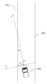
- FIG. 2 is a plan view showing road edge departure prevention control in the first embodiment of the present invention.
- 4 is a flowchart showing road edge departure suppression control in the first embodiment of the present invention.
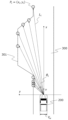
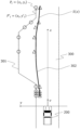
- FIG. 2 is a plan view showing an example of road edge detection in the first embodiment of the present invention.
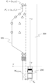
- FIG. 4 is a plan view showing an example of correction of a road edge detection position in the first embodiment of the present invention.
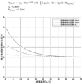
- FIG. 10 is a graph showing the relationship between the y coordinate of the road edge detection position and the y coordinate of the corrected road edge detection position in the first embodiment of the present invention.
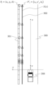
- FIG. 2 is a plan view showing an example of a virtual road edge in the first embodiment of the present invention.
- FIG. 11 is a diagram showing the effect of the first embodiment of the present invention.
- FIG. 11 is a plan view showing an example of a virtual road edge in the second embodiment of the present invention.
- FIG. 11 is a diagram showing the effect of the second embodiment of the present invention.
- FIG. 13 is a diagram showing the effect of the third embodiment of the present invention.
- FIG. 1 is a block diagram showing the configuration of a vehicle control device according to a first embodiment of the present invention.
- the vehicle control device 100 includes a road edge detection unit 110, a vehicle information acquisition unit 120, a controller 130, and a vehicle control unit 140.
- the road edge detection unit 110 is composed of a stereo camera etc., and detects the road edge ahead of the vehicle and transmits it to the controller 130.
- the host vehicle information acquisition unit 120 is composed of a speed sensor 121, a steering angle sensor 122, a yaw rate sensor 123, an acceleration sensor 124, etc., and acquires information related to the host vehicle (hereinafter, host vehicle information).
- the speed sensor 121 detects the vehicle speed of the host vehicle and transmits it to the controller 130.
- the speed sensor 121 constitutes the vehicle speed detection unit of the vehicle control device 100.
- the steering angle sensor 122 detects the angle of the steering wheel of the host vehicle, i.e., the steering angle, and transmits it to the controller 130.
- the yaw rate sensor 123 detects the yaw rate of the host vehicle and transmits it to the controller 130.
- the acceleration sensor 124 detects the acceleration of the host vehicle and transmits it to the controller 130.
- the acceleration sensor 124 constitutes the acceleration detection unit of the vehicle control device 100.
- the controller 130 generates a virtual road edge based on the road edge detection results from the road edge detection unit 110 and the vehicle information acquired by the vehicle information acquisition unit 120, and outputs an HMI command to notify the driver when deviation prevention from the virtual road edge is necessary, and outputs a steering command to prevent deviation from the virtual road edge.
- the controller 130 constitutes the virtual road edge generation unit of the vehicle control device 100.
- the vehicle control unit 140 is composed of a human machine interface (hereinafter, HMI) unit 141, a steering system 142, etc.
- HMI human machine interface
- the HMI unit 141 performs warning control, display, steering vibration, and other driver notifications based on HMI commands calculated by the controller 130.
- the steering system 142 performs steering control based on steering commands calculated by the controller 130.
- the vehicle control unit 140 has a road departure prevention function (RDP: Road Departure Prevention) and constitutes the road edge departure prevention control unit of the vehicle control device 100.
- the road departure prevention function is a function that issues a warning to the driver and automatically steers the vehicle so that the vehicle does not depart from the road.
- the lane departure prevention function (LDP: Lane Departure Prevention) is a function that issues a warning to the driver and automatically steers the vehicle so that the vehicle does not depart from the lane.
- ⁇ rdp is the target yaw rate
- Kstr, Kd, and K ⁇ are control gains.
- the target yaw rate ⁇ rdp is calculated from the road edge lateral position deviation yd of the host vehicle 200 detected by the road edge detection unit 110 and the road edge 301 detected by the road edge detection unit 110, and the yaw angle ⁇ r of the host vehicle 200 relative to the road edge 301 detected by the road edge detection unit 110.
- the steering torque Trdp is calculated from the target yaw rate ⁇ rdp and the yaw rate ⁇ of the host vehicle 200 detected by the yaw rate sensor 123. Specifically, the steering torque Trdp is calculated by multiplying the difference obtained by subtracting the yaw rate ⁇ from the target yaw rate ⁇ rdp by a parameter Kstr corresponding to the steering characteristics of the host vehicle 200.
- the HMI unit 141 has a function for notifying the driver by using a screen display, a buzzer, steering wheel vibration, etc., and is used to notify the driver by output from the controller 130 when there is a possibility that the vehicle 200 may deviate from the road edge 301.
- the steering system 142 is specifically a steering system such as EPS (Electric Power Steering), and when there is a possibility that the host vehicle 200 may deviate from the road edge 301, the steering system 142 generates a yaw moment in the host vehicle 200 by outputting the controller 130, thereby generating a steering torque for returning the host vehicle 200 to the road 300.
- EPS Electrical Power Steering
- FIG. 3 is a flowchart showing the road edge departure prevention control executed by the vehicle control device 100.
- the controller 130 acquires the vehicle speed v of the host vehicle 200, etc., via the host vehicle information acquisition unit 120 (step S101).
- the road edge detection unit 110 acquires the detected road edge position ahead of the vehicle (step S102).
- step S102 the road edge detection position is corrected according to the vehicle speed v of the host vehicle 200 (step S103).
- a corrected road edge detection position to be used for generating a virtual road edge is selected from the corrected road edge detection positions (hereinafter, corrected road edge detection positions), and a virtual road edge 302 is generated from the selected corrected road edge detection position (step S104).
- step S104 road edge departure prevention control is implemented based on the generated virtual road edge 302 (S106), and the flow ends.
- Figure 4 shows an example of road edge detection using a stereo camera. It is assumed that the distance Li to the road edge 301 can be detected in 1.5 degree increments at angles ⁇ i within the viewing angle range of the stereo camera, and the road edge detection position is defined in a two-dimensional xy plane with the x coordinate representing the vehicle's traveling direction and the y coordinate representing the vehicle's lateral direction, as shown in equation (2).
- An example of the correction of the road edge detection position is shown in Figure 5.
- the y-coordinate y'i of the corrected road edge detection position P'i is defined as a function f of the y-coordinate yi of the road edge detection position Pi detected by the road edge detection unit 110 and the vehicle speed v detected by the speed sensor 21, as shown in equation (3).
- Equation (3) An example of the function f in equation (3) is shown in equation (4).
- Figure 6 is a graph showing the relationship between the y-coordinate yi of the road edge detection position Pi and the y-coordinate y'i of the corrected road edge detection position P'i, and is an example in which the vehicle width VW is 1.8 m and the allowable offset amount Woffset to the virtual lane boundary is 1.1 m in equation (4).
- Equation (4) makes it possible to generate a virtual road edge 302 that ensures an offset W from the road edge 301 along the driving direction of the vehicle 200. Therefore, the higher the vehicle speed v, the more offset W can be ensured, and a straight virtual road edge 302 can be generated that is aligned with the driving direction of the vehicle 200.
- position correction is performed using equations such as (3) and (4).
- a map of the y-coordinate yi of the road edge detection position Pi and the vehicle speed v may be created, and position correction may be performed using the map.
- An example of the virtual road edge generated in step S104 is shown in FIG. 7.
- Equation (5) is the basic equation for the B-spline curve S(x).
- Ni,p are the basis functions of the B-spline
- n is the number of control points
- p is the order of the basis function
- step S105 the controller 130 determines whether or not there is a possibility that the host vehicle 200 will deviate from the virtual road edge 302 based on the vehicle speed v detected by the speed sensor 121, the steering angle detected by the steering angle sensor 122, the yaw rate ⁇ of the host vehicle 200 detected by the yaw rate sensor 123, and the virtual road edge 302, and if there is a possibility that the host vehicle 200 will deviate from the virtual road edge 302, calculates a control amount and HMI notification to generate a yaw moment in the host vehicle 200 and return the host vehicle 200 to the center of the road.
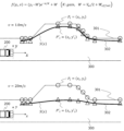
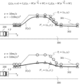
- FIG. 8 shows the effect of the present invention in the first embodiment.
- the upper diagram in Figure 8 is an example of a virtual road edge 302 generated when driving at low speed.
- the degree of position correction in step S103 is small, so a virtual road edge 302 is generated that aligns with the actual road edge 301.
- the lower diagram in Figure 8 shows an example of a virtual road edge 302 generated when driving at high speed.
- the degree of position correction in step S103 increases, so the road edge detection position Pi, which is far away laterally from the vehicle 200, is significantly corrected toward the vehicle to generate the virtual road edge 302.
- the virtual road edge generating unit 130 in the first embodiment corrects the detected position Pi of the road edge 301 so that the detected position Pi of the road edge 301 approaches the host vehicle 200 as the vehicle speed v of the host vehicle 200 increases.
- the virtual road edge 302 is generated closer to the host vehicle as the vehicle speed v of the host vehicle 200 increases, making it possible to reduce the possibility of the host vehicle 200 straying off the road edge 301.
- the second embodiment of the present invention will be described, focusing on the differences from the first embodiment.
- a method for generating a virtual road edge 302 according to the vehicle speed v was described, but in this embodiment, a method for generating a virtual road edge 302 taking into account the elevation difference between the road surface of the road 300 and the road edge 301 will be described.
- Steps S101, S104, and S105 are the same as in the first embodiment, so the explanation will be omitted.
- the elevation difference h of the road edge 301 is an example of environmental information of the road edge 301.
- the y coordinate y'i of the corrected road edge detection position P'i is expressed as a function fh of the y coordinate yi of the road edge detection position Pi, the vehicle speed v, and the elevation difference h of the road edge, as shown in equation (6).
- K(h) is a gain according to the elevation difference h of the road edge, and is defined, for example, by equation (8).
- the road edge detection position Pi can be offset toward the vehicle.
- Function fh may also be defined as a cost function of vehicle speed v and elevation difference h of the road edge 301, as in equation (9).
- Cv and Ch are the weights of the cost function, and the sum of the weights is set to 1.
- position correction is performed using a formula such as formula (6), (7), or (9).
- position correction may be performed by creating a map of the y-coordinate yi of the road edge detection position Pi and the elevation difference h of the road edge 301.
- FIG. 9 is a plan view showing an example of a virtual road edge 302 in the second embodiment.
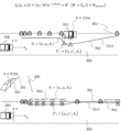
- FIG. 10 shows the effect of the present invention in the second embodiment.
- the vehicle speed v is 0 to show the effect of the elevation difference h.
- the upper diagram in Figure 10 shows an example in which a parked vehicle 201 is detected.
- the road edge detection position Pi is offset toward the vehicle itself by position correction in step S103, and a virtual road edge 302 is generated.
- the virtual road edge generating unit 130 in the second embodiment corrects the detected position Pi of the road edge 301 based on the environmental information of the road edge 301 .
- the second embodiment configured as described above provides the same effects as the first embodiment, and also makes it possible to generate a virtual road edge 302 that takes into account environmental information about the road edge 301.
- the virtual road edge generating unit 130 in the second embodiment corrects the detected position Pi of the road edge 301 so that the greater the difference in elevation h between the road surface of the road 300 and the road edge 301, among the environmental information of the road edge 301, the closer the detected position Pi of the road edge 301 is to the vehicle 200.
- the greater the difference in elevation h between the road surface of the road 300 and the road edge 301 the closer the virtual road edge 302 is generated to the vehicle, thereby making it possible to reduce the possibility of contact with a curb 303 or the like or of the vehicle running off the road.
- the third embodiment of the present invention will be described, focusing on the differences from the first and second embodiments.
- a method for generating a virtual road edge 302 in accordance with the vehicle speed v of the host vehicle 200 and the elevation difference h of the road edge 301 was described.
- a method for generating a virtual road edge 302 in accordance with the vehicle speed v and acceleration a of the host vehicle 200 will be described.
- the y coordinate y'i of the corrected road edge detection position P'i is defined as a function fa of the y coordinate yi of the road edge detection position Pi, the vehicle speed v, and the acceleration a, as shown in equation (10).
- the function fa is expressed as a cost function of the vehicle speed v and acceleration a, as shown in equation (11).
- Cv and Ca are weights of the cost function, and are set so that the sum of the weights Cv and Ca is 1. According to formula (11), when either the vehicle speed v or the acceleration a is large, the road edge detection position Pi can be offset toward the vehicle.
- the second and third embodiments may be combined to define a function that performs position correction as shown in equation (12).
- Cv, Ch, and Ca are the weights of the cost function, and are set so that the sum of the weights is 1.
- FIG. 11 is a diagram showing the effect of the present invention in the third embodiment.
- the example in FIG. 10 shows an example in which acceleration and deceleration are performed when the vehicle is traveling at a speed v of 10 m/s.
- the upper diagram in Figure 11 shows an example of a virtual road edge 302 generated during deceleration, where the virtual road edge 302 is generated so as to approach the actual road edge 301 by position correction in step S103).
- the lower diagram in Figure 11 shows an example of a virtual road edge 302 that is generated during acceleration.
- the road edge detection position Pi is offset toward the vehicle by the position correction in step S103, and the virtual road edge 302 is generated.
- the virtual road edge generating unit 130 in the third embodiment corrects the detected position Pi of the road edge 301 so that the fluctuation of the detected position Pi of the road edge 301 relative to the traveling direction of the host vehicle 200 becomes smaller as the acceleration a of the host vehicle 200 becomes larger.
- the third embodiment configured as described above also provides the same effects as the first embodiment. Furthermore, excessive steering is suppressed when accelerating the vehicle 200, and the vehicle 200 can be moved closer to the road edge 301 when decelerating, making it possible to realize driving operations that are not contrary to the driver's intentions.
- the virtual road edge generating unit 130 corrects the detection position Pi of the road edge 301 so that the detection position Pi of the road edge 301 approaches the host vehicle 200 as the acceleration a of the host vehicle 200 increases.
- the virtual road edge 302 is generated closer to the host vehicle as the acceleration a of the host vehicle 200 increases, making it possible to reduce the possibility of the host vehicle 200 straying off the road edge 301.
- the present invention is not limited to the above-described embodiments, but includes various modified examples.
- the above-described embodiments are shown to clearly explain the present invention, and are not necessarily limited to those having all of the configurations described. It is also possible to replace part of the configuration of one embodiment with the configuration of another embodiment, and it is also possible to add the configuration of another embodiment to the configuration of one embodiment. It is also possible to add, delete, or replace part of the configuration of each embodiment with other configurations.
- 100...vehicle control device 110...road edge detection unit, 120...own vehicle information acquisition unit, 121...speed sensor (vehicle speed detection unit), 122...steering angle sensor, 123...yaw rate sensor, 124...acceleration sensor (acceleration detection unit), 130...controller (virtual road edge generation unit), 140...vehicle control unit (road edge departure prevention control unit), 141...HMI unit, 142...steering system, 200...own vehicle, 201...parked vehicle, 300...road, 301...road edge, 302...virtual road edge, 303...curb.
Landscapes
- Engineering & Computer Science (AREA)
- Physics & Mathematics (AREA)
- Chemical & Material Sciences (AREA)
- Combustion & Propulsion (AREA)
- Transportation (AREA)
- Mechanical Engineering (AREA)
- General Physics & Mathematics (AREA)
- Mathematical Physics (AREA)
- Traffic Control Systems (AREA)
Abstract
本発明は、複雑な道路端形状を有する道路を走行する際も、ドライバ干渉を抑制しつつ道路端逸脱抑止制御を実行することが可能な車両制御装置を提供することを目的とする。そのために、車両制御装置100は、自車両200が走行する道路300の道路端301を検出する道路端検出部110と、自車両200の車速vを検出する車速検出部121と、車速vが大きい程、自車両200の走行方向に対する道路端301の検知位置Piの変動が小さくなるように道路端301の検知位置Piを補正し、補正後の道路端301の検知位置P'iに基づいて仮想道路端302を生成する仮想道路端生成部130と、仮想道路端302からの自車両200の逸脱を抑制するように自車両200の操舵制御を実行する路端逸脱抑制制御部140とを備える。
Description
本発明は、車両制御装置に関し、特に、車両が道路を逸脱しないように自動的に操舵を行う車両制御装置に関する。
特許文献1に提案されているように、車両が道路を逸脱しそうな場合に車両へヨーモーメントを発生させ逸脱を抑止させる道路端逸脱抑止制御を実施する車両運転装置が知られている。
例えば、外界認識センサとしてカメラで自車両の走行する道路端を検出し、道路端に対するヨー角や横位置に応じて自車両が道路端の外へ逸脱する恐れがある場合に、自車両のステアリングに操舵トルクを付与し自車両へヨーモーメントを発生することによって逸脱を抑止する制御である。
また、特許文献2のように、走行車線の白線上に他車両などの障害物が存在する場合に、障害物に対して仮想の車線を設定し、設定した仮想車線により車両の制御を行う車両制御装置がある。
特許文献1では、接触の危険がある道路端に対して制御量を変え逸脱抑止することが提案されている。特許文献1の技術では、制御対象の道路端が平坦であるか立体物かを判定し、立体物であれば接触しないよう道路端の外へ逸脱させない制御量とし、平坦であれば制御対象に対して多少逸脱しても良いとして、ドライバの運転操作と干渉するような過剰な操舵トルクが発生しない制御量に変更できるようになっている。
しかしながら、実際の道路端形状は不定であることが多く、草むらに接した道路の道路端のように高さや形状が不連続な道路端に対して制御量を決めてしまうと、操舵トルクの制御量が頻繁に切り替わることでドライバに煩わしさを感じさせてしまう可能性がある。
このように道路端逸脱抑止制御は、道路端形状が不定なため正しく道路端を判定できずドライバ干渉を生じてしまう問題があり、市場に出ている道路端逸脱抑止制御技術は、道路端形状が直線的である場合に限定して実施されているが、道路の外へ逸脱すると、縁石等との接触や脱輪の可能性もあるため、道路端逸脱抑止制御は積極的に作動させることが望まれる。
一方で、特許文献2では、障害物に対して仮想車線を設定することで、ドライバの意思に沿った制御が行えることが提案されている。特許文献2の仮想車線設定技術では、走行車線の白線上に他車両などの障害物が存在する場合に、障害物に対して仮想の車線を設定し、障害物と実際の車線境界とを自車両の走行速度により決定される長さで結ぶことで仮想車線を設定するようになっている。
しかしながら、自車両近傍の道路端を始点に仮想車線が生成されるため、草むらに接した道路のような複雑な道路端形状を有する道路の走行時に、自車両に対する仮想車線との角度が頻繁に切り替わることでドライバの運転操作と干渉する可能性がある。
本発明は、上記の課題に鑑みてなされたものであり、その目的は、複雑な道路端形状を有する道路の走行時も、ドライバ干渉を抑制しつつ道路端逸脱抑止制御を実行することが可能な車両制御装置を提供することにある。
上記目的を達成するために、本発明は、自車両が走行する道路の道路端を検出する道路端検出部と、前記自車両の車速を検出する車速検出部と、前記車速が大きい程、前記自車両の走行方向に対する前記道路端の検知位置の変動が小さくなるように前記道路端の検知位置を補正し、補正後の前記道路端の検知位置に基づいて仮想道路端を生成する仮想道路端生成部と、前記仮想道路端からの前記自車両の逸脱を抑制するように前記自車両の操舵制御を実行する道路端逸脱抑制制御部とを備えるものとする。
本発明によれば、複雑な道路端形状を有する道路の走行時も、ドライバ干渉を抑制しつつ道路端逸脱抑止制御を実行することが可能となる。
以下、本発明の実施形態を図面に基づいて説明する。なお、各図中、同等の部材には同一の符号を付し、重複した説明は省略する。
図1は、本発明の第1の実施例に係る車両制御装置の構成を示すブロック図である。車両制御装置100は、道路端検出部110と、自車両情報取得部120と、コントローラ130と、車両制御部140とを備える。
道路端検出部110は、ステレオカメラ等で構成され、自車両前方の道路端を検出し、コントローラ130に送信する。
自車両情報取得部120は、速度センサ121、舵角センサ122、ヨーレートセンサ123、加速度センサ124等で構成され、自車両に関わる情報(以下、自車両情報)を取得する。速度センサ121は、自車両の車速を検出し、コントローラ130に送信する。速度センサ121は、車両制御装置100の車速検出部を構成している。舵角センサ122は、自車両のステアリングホイールの角度、即ち舵角を検出し、コントローラ130に送信する。ヨーレートセンサ123は、自車両のヨーレートを検出し、コントローラ130に送信する。加速度センサ124は、自車両の加速度を検出し、コントローラ130に送信する。加速度センサ124は、車両制御装置100のか加速度検出部を構成している。
コントローラ130は、道路端検出部110からの道路端検出結果と自車両情報取得部120で取得される自車両情報とに基づいて仮想道路端を生成し、仮想道路端に対する逸脱抑制が必要な場合にドライバへの通知を行うHMI指令を出力するとともに、仮想道路端に対する逸脱抑制を行うための操舵指令を出力する。コントローラ130は、車両制御装置100の仮想道路端生成部を構成している。
車両制御部140は、ヒューマンマシンインタフェース(以下、HMI)部141、操舵システム142等で構成される。HMI部141は、コントローラ130で算出されるHMI指令に基づいて、警報制御や表示、ステアリング振動等のドライバ通知を行う。操舵システム142は、コントローラ130で算出される操舵指令に基づいて操舵制御を行う。車両制御部140は、道路逸脱抑制機能(RDP:Road Departure Prevention)を有しており、車両制御装置100の道路端逸脱抑制制御部を構成している。道路逸脱抑制機能は、自車両が道路を逸脱しないように運転手に警告を発したり、自動的に操舵を行う機能である。これに対し、車線逸脱抑制機能(LDP:Lane Departure Prevention)は、自車両が車線を逸脱しないように運転手に警告を発したり、自動的に操舵を行う機能である。
コントローラ130は、速度センサ121、舵角センサ122、ヨーレートセンサ123および道路端検出部110からの情報に基づいて、自車両の走行する道路端を検出し、道路端に対するヨー角や横位置に応じて自車両が道路端の外へ逸脱する恐れがある場合に、逸脱しないように自車両へヨーモーメントを発生させるよう自車両のステアリングに付与する操舵トルクとドライバへの警報報知タイミングを算出する、道路端逸脱抑止制御手段として機能する。なお、本実施例では、操舵トルクを算出するが、それに代えて、道路端の外へ逸脱しないように自車両へヨーモーメントを発生させるようための目標舵角を算出しても良い。
図2は、車両制御装置100の道路端逸脱抑止制御を示す平面図である。
コントローラ130は、式(1)に基づいて操舵トルクTrdpを算出する。

ここで、γrdpは目標ヨーレートであり、Kstr,Kd,Kθはそれぞれ制御ゲインである。道路端検出部110で検出された自車両200と道路端横位置偏差ydと、道路端検出部110で検出された道路端301に対する自車両200のヨー角θrとから、目標ヨーレートγrdpを算出する。
目標ヨーレートγrdpとヨーレートセンサ123で検出された自車両200のヨーレートγから操舵トルクTrdpを算出する。具体的には、目標ヨーレートγrdpからヨーレートγを引いた差分に自車両200の操舵特性に応じたパラメータKstrをかけることで操舵トルクTrdpを算出する。
HMI部141は、画面表示やブザー、ステアリングホイール振動等のドライバへの報知を行う機能であり、自車両200が道路端301の外へ逸脱する可能性がある場合に、コントローラ130からの出力により、ドライバへ報知を行うためのものである。
操舵システム142は、具体的にはEPS(Electric Power Steering)等の操舵システムであり、自車両200が道路端301の外へ逸脱する可能性がある場合に、コントローラ130の出力により、自車両200にヨーモーメントを発生させ自車両200を道路300内に戻すための操舵トルクを発生させるものである。
図3は、車両制御装置100にて実行される道路端逸脱抑制制御を示すフローチャートである。
コントローラ130は、まず、自車両情報取得部120により、自車両200の車速v等を取得する(ステップS101)。
ステップS101に続き、道路端検出部110により、自車両前方の道路端検知位置を取得する(ステップS102)。
ステップS102に続き、自車両200の車速vに応じて、道路端検知位置を補正する(ステップS103)。
ステップS103に続き、補正された道路端検知位置(以下、補正後道路端検知位置)から仮想道路端の生成に利用する補正後道路端検知位置を選定し、選定した補正後道路端検知位置から仮想道路端302を生成する(ステップS104)。
ステップS104に続き、生成された仮想道路端に302に基づいて、道路端逸脱抑制制御を実施し(S106)、当該フローを終了する。
ステップS102において、道路端検出部110により取得される、自車両前方の道路端検出結果は、道路端検知位置Pi=(xi,yi)の集合として得られることとする。
図4は、ステレオカメラによる道路端検出の例を示している。ステレオカメラの画角範囲内の角度θiにおいて1.5度刻みに道路端301までの距離Liが検出できることとし、式(2)のように、自車進行方向をx座標、自車横方向をy座標とする二次元xy平面での道路端検知位置を定義する。

ステップS103では、道路端検知位置Pi=(xi,yi)を補正して、補正後道路端検知位置P’i=(xi,y’i)を生成する。道路端検知位置の補正例を図5に示す。
補正後道路端検知位置P’iのy座標y’iは、式(3)に示すように、道路端検出部110により検出された道路端検知位置Piのy座標yiと、速度センサ21により検出された車速vとの関数fで定義される。

式(3)の関数fの例を式(4)に示す。

図6は、道路端検知位置Piのy座標yiと補正後道路端検知位置P’iのy座標y’iとの関係を示すグラフ図であり、式(4)において、自車幅VWを1.8m、仮想車線境界までの許容オフセット量Woffsetを1.1mとした場合の例である。
式(4)により、道路端301から自車両200の走行方向に沿ってオフセットWを確保した仮想道路端302を生成することができるため、車速vが大きい程、オフセットWを確保し、自車両200の走行方向に沿った直線的な仮想道路端302を生成することができる。
なお、本実施例では、式(3),(4)のように数式で位置補正を行うが、それに代えて、道路端検知位置Piのy座標yiと車速vのマップを作成し、当該マップを用いて位置補正を行っても良い。
図3に戻り、ステップS104において、本実施例では補正後道路端検知位置P’i=(xi,y’i)を制御点とするBスプライン曲線S(x)を生成し、離散点である補正後道路端検知位置P’iを補間して仮想道路端を生成する。ステップS104で生成される仮想道路端の例を図7に示す。
式(5)はBスプライン曲線S(x)の基本式である。

ここで、Ni,pはBスプラインの基底関数、nは制御点数、pは基底関数の次数である。
なお、仮想道路端302は、上述したBスプライン曲線以外の曲線として設定されても良く、例えば補正後道路端検知位置P’i=(xi,y’i)に対してn次関数をフィッティングすることにより仮想道路端302を生成しても良い。
ステップS105では、コントローラ130は、速度センサ121により検出された車速vと、舵角センサ122により検出された操舵角と、ヨーレートセンサ123より検出された自車両200のヨーレートγと、仮想道路端302とに基づいて、自車両200が仮想道路端302の外へ逸脱する可能性の有無を判断し、自車両200が仮想道路端302の外へ逸脱する可能性がある場合に、自車両200にヨーモーメントを発生させ自車両200を道路中央寄りに戻すための制御量とHMI通知の算出を行う。
図8は、第1の実施例における本発明の効果を示す図である。
図8の上図は、低速走行時に生成される仮想道路端302の例である。車速vが小さい場合は、ステップS103での位置補正の度合いが小さくなるため、実際の道路端301に沿うような仮想道路端302が生成される。
図8の下図は、高速走行時に生成される仮想道路端302の例である。車速vが大きい場合は、ステップS103での位置補正の度合いが大きくなるため、自車両200の横方向遠方にある道路端検知位置Piが自車両寄りに大きく補正されて仮想道路端302が生成される。
(まとめ)
第1の実施例における車両制御装置100は、自車両200が走行する道路300の道路端301を検出する道路端検出部110と、自車両200の車速vを検出する車速検出部121と、車速vが大きい程、自車両200の走行方向に対する道路端301の検知位置Piの変動が小さくなるように道路端301の検知位置Piを補正し、補正後の道路端301の検知位置P’iに基づいて仮想道路端302を生成する仮想道路端生成部130と、仮想道路端302の外への自車両200の逸脱を抑制するように自車両200の操舵制御を実行する道路端逸脱抑制制御部140とを備える。
第1の実施例における車両制御装置100は、自車両200が走行する道路300の道路端301を検出する道路端検出部110と、自車両200の車速vを検出する車速検出部121と、車速vが大きい程、自車両200の走行方向に対する道路端301の検知位置Piの変動が小さくなるように道路端301の検知位置Piを補正し、補正後の道路端301の検知位置P’iに基づいて仮想道路端302を生成する仮想道路端生成部130と、仮想道路端302の外への自車両200の逸脱を抑制するように自車両200の操舵制御を実行する道路端逸脱抑制制御部140とを備える。
以上のように構成した第1の実施例によれば、自車両200の車速vが大きい程、走行方向に沿った形状となる仮想道路端302に対して路端逸脱抑制制御が実行されるため、高速走行時に路端逸脱抑制制御による過剰な操舵を抑制することができる。一方、低速走行時には仮想道路端302の形状が実際の道路端301の形状に近くなるため、自車両200を道路端301に寄せることができる。これにより、複雑な道路端形状を有する道路の走行時も、ドライバ干渉を抑制しつつ道路端逸脱抑止制御を実行することが可能となる。
また、第1の実施例における仮想道路端生成部130は、自車両200の車速vが大きい程、道路端301の検知位置Piが自車両200に近づくように道路端301の検知位置Piを補正する。これにより、自車両200の車速vが大きい程、仮想道路端302が自車両寄りに生成されるため、自車両200が道路端301の外へ逸脱する可能性を低減することが可能となる。
本発明の第2の実施例について、第1の実施例との相違点を中心に説明する。第1の実施例では、車速vに応じて仮想道路端302を生成する方法を説明したが、本実施例では、道路300の路面と道路端301との高低差も考慮して仮想道路端302を生成する方法について説明する。
ステップS101,S104,S105は第1の実施例と同様であるため、説明は省略する。
ステップS102において、道路端検出部110により、自車両前方の道路端301を検出できた際、道路端検知位置Pi=(xi,yi,hi)として位置と高さが得られることとし、高さhiは道路300の路面との高低差とする。道路端301の高低差hは、道路端301の環境情報の一例である。
ステップS103において、道路端検知位置Pi=(xi,yi,hi)を補正して、補正後道路端検知位置P’i=(xi,y’i,hi)を生成する。ここで、補正後道路端検知位置P’iのy座標y’iは、式(6)のように、道路端検知位置Piのy座標yi、車速vおよび道路端の高低差hの関数fhで表される。

関数fhの例を式(7)に示す。

ここで、K(h)は道路端の高低差hに応じたゲインであり、例えば式(8)で定義される。

ここで、aは任意の正の数である。
式(7),(8)のように関数fhを定義することにより、車速vと道路端301の高低差hのいずれかが大きい場合に、道路端検知位置Piを自車両寄りにオフセットすることができる。
また、関数fhは、式(9)のように、車速vと道路端301の高低差hのコスト関数で定義しても良い。

ここで、Cv,Chはコスト関数の重みであり、重みの総和が1になるように設定される。
なお、本実施例では、式(6),(7)または式(9)のように数式で位置補正を行うが、それに代えて、道路端検知位置Piのy座標yiと道路端301の高低差hのマップを作成し位置補正を行っても良い。
図9は、第2の実施例における仮想道路端302の例を示す平面図である。
図10は、第2の実施例における本発明の効果を示す図である。
図10の例では、高低差hによる効果を示すために車速vが0であった場合の例を示している。
図10の上図は駐車車両201を検出した例であり、駐車車両201の位置ではステップS103での位置補正により道路端検知位置Piが自車両寄りにオフセットされ、仮想道路端302が生成される。
図9の下図は縁石303を検出した例であり、縁石303の位置ではステップS103での位置補正により道路端検知位置Piが自車両寄りにオフセットされ、仮想道路端302が生成される。
(まとめ)
第2の実施例における仮想道路端生成部130は、道路端301の環境情報に基づいて道路端301の検知位置Piを補正する。
第2の実施例における仮想道路端生成部130は、道路端301の環境情報に基づいて道路端301の検知位置Piを補正する。
以上のように構成した第2の実施例によれば、第1の実施例と同様の効果が得られるとともに、道路端301の環境情報を考慮した仮想道路端302を生成することが可能となる。
また、第2の実施例における仮想道路端生成部130は、道路端301の環境情報のうち、道路300の路面と道路端301との高低差hが大きい程、道路端301の検知位置Piが自車両200に近づくように道路端301の検知位置Piを補正する。これにより、道路300の路面と道路端301との高低差hが大きい程、仮想道路端302が自車両寄りに生成されるため、縁石303等との接触や脱輪の可能性を低減することが可能となる。
本発明の第3の実施例について、第1および第2の実施例との相違点を中心に説明する。第1および第2の実施例では、自車両200の車速vと道路端301の高低差hに応じて仮想道路端302を生成する方法を説明したが、本実施例では、自車両200の車速vと加速度aに応じて仮想道路端302を生成する方法について説明する。
図3において、ステップS101,S102,S104,S105は第1の実施例と同様であるため、説明は省略する。
ステップS103では、道路端検知位置Pi=(xi,yi)を補正して、補正後道路端検知位置P’i=(xi,y’i)を生成する。ここで、補正後道路端検知位置P’iのy座標y’iは、式(10)のように、道路端検知位置Piのy座標yi、車速vおよび加速度aの関数faで定義される。

関数faは、式(11)に示すように、車速vおよび加速度aのコスト関数で表現することとする。

ここで、Cv,Caはコスト関数の重みであり、重みCv,Caの総和が1になるように設定される。式(11)により、車速vおよび加速度aのいずれかが大きい場合に、道路端検知位置Piを自車両寄りにオフセットすることができる。
また、車速vで同じであっても、自車両200が減速している(加速度aがマイナスになる)場合には、加速度aによる補正と車速vによる補正とが相殺されるため、補正後道路端検知位置P’i=(xi,y’i)を実際の道路端301に近づけることができる。
さらに、第2および第3の実施例を組み合わせ、式(12)のように位置補正を実施する関数を定義しても良い。

ここで、Cv,Ch,Caはコスト関数の重みであり、重みの総和が1になるように設定される。
図11は、第3の実施例における本発明の効果を示す図である。図10の例では、車速vを10m/sで走行している際に加減速度を行った例を示している。
図11の上図は、減速時に生成される仮想道路端302の例であり、ステップS103)での位置補正により実際の道路端301に近づくように仮想道路端302が生成される。
図11の下図は、加速時に生成される仮想道路端302の例であり、ステップS103での位置補正により道路端検知位置Piが自車両寄りにオフセットされ、仮想道路端302が生成される。
(まとめ)
第3の実施例における仮想道路端生成部130は、自車両200の加速度aが大きい程、自車両200の走行方向に対する道路端301の検知位置Piの変動が小さくなるように道路端301の検知位置Piを補正する。
第3の実施例における仮想道路端生成部130は、自車両200の加速度aが大きい程、自車両200の走行方向に対する道路端301の検知位置Piの変動が小さくなるように道路端301の検知位置Piを補正する。
以上のように構成した第3の実施例においても、第1の実施例と同様の効果が得られる。さらに、自車両200の加速時には過剰な操舵が抑えられ、減速時には自車両200を道路端301に寄せることできるため、ドライバの意図に反しない走行動作を実現することが可能となる。
また、第3の実施例における仮想道路端生成部130は、自車両200の加速度aが大きい程、道路端301の検知位置Piが自車両200に近づくように道路端301の検知位置Piを補正する。これにより、自車両200の加速度aが大きい程、仮想道路端302が自車両寄りに生成されるため、自車両200が道路端301の外へ逸脱する可能性を低減することが可能となる。
なお、本発明は上記した実施例に限定されるものではなく、様々な変形例が含まれる。例えば、上記した実施例は本発明をわかりやすく説明するために示したものであり、必ずしも説明した全ての構成を備えるものに限定されるものではない。また、ある実施例の構成の一部を他の実施例の構成に置き換えることが可能であり、また、ある実施例の構成に他の実施例の構成を加えることも可能である。また、各実施例の構成の一部について、他の構成の追加・削除・置換をすることが可能である。
100…車両制御装置、110…道路端検出部、120…自車両情報取得部、121…速度センサ(車速検出部)、122…舵角センサ、123…ヨーレートセンサ、124…加速度センサ(加速度検出部)、130…コントローラ(仮想道路端生成部)、140…車両制御部(道路端逸脱抑制制御部)、141…HMI部、142…操舵システム、200…自車両、201…駐車車両、300…道路、301…道路端、302…仮想道路端、303…縁石。
Claims (6)
- 自車両が走行する道路の道路端を検出する道路端検出部と、
前記自車両の車速を検出する車速検出部と、
前記車速が大きい程、前記自車両の走行方向に対する前記道路端の検知位置の変動が小さくなるように前記道路端の検知位置を補正し、補正後の前記道路端の検知位置に基づいて仮想道路端を生成する仮想道路端生成部と、
前記仮想道路端からの前記自車両の逸脱を抑制するように前記自車両の操舵制御を実行する道路端逸脱抑制制御部とを備える
ことを特徴とする車両制御装置。 - 請求項1に記載の車両制御装置において、
前記仮想道路端生成部は、前記車速が大きい程、前記道路端の検知位置が前記自車両に近づくように前記道路端の検知位置を補正する
ことを特徴とする車両制御装置。 - 請求項1に記載の車両制御装置において、
前記仮想道路端生成部は、前記道路端の環境情報に基づいて前記道路端の検知位置を補正する
ことを特徴とする車両制御装置。 - 請求項3に記載の車両制御装置において、
前記仮想道路端生成部は、前記環境情報のうち、前記道路の路面と前記道路端との高低差が大きい程、前記道路端の検知位置が前記自車両に近づくように前記道路端の検知位置を補正する
ことを特徴とする車両制御装置。 - 請求項1に記載の車両制御装置において、
前記自車両の加速度を検出する加速度検出部を備え、
前記仮想道路端生成部は、前記加速度が大きい程、前記走行方向に対する前記道路端の検知位置の変動が小さくなるように前記道路端の検知位置を補正する
ことを特徴とする車両制御装置。 - 請求項1に記載の車両制御装置において、
前記自車両の加速度を検出する加速度検出部を備え、
前記仮想道路端生成部は、前記加速度が大きい程、前記道路端の検知位置が前記自車両に近づくように前記道路端の検知位置を補正する
ことを特徴とする車両制御装置。
Priority Applications (4)
| Application Number | Priority Date | Filing Date | Title |
|---|---|---|---|
| PCT/JP2023/045640 WO2025134256A1 (ja) | 2023-12-20 | 2023-12-20 | 車両制御装置 |
| DE112023006703.1T DE112023006703T5 (de) | 2023-12-20 | 2023-12-20 | Fahrzeugsteuervorrichtung |
| JP2025564691A JPWO2025134256A1 (ja) | 2023-12-20 | 2023-12-20 | |
| CN202380102322.4A CN121866190A (zh) | 2023-12-20 | 2023-12-20 | 车辆控制装置 |
Applications Claiming Priority (1)
| Application Number | Priority Date | Filing Date | Title |
|---|---|---|---|
| PCT/JP2023/045640 WO2025134256A1 (ja) | 2023-12-20 | 2023-12-20 | 車両制御装置 |
Publications (1)
| Publication Number | Publication Date |
|---|---|
| WO2025134256A1 true WO2025134256A1 (ja) | 2025-06-26 |
Family
ID=96137694
Family Applications (1)
| Application Number | Title | Priority Date | Filing Date |
|---|---|---|---|
| PCT/JP2023/045640 Pending WO2025134256A1 (ja) | 2023-12-20 | 2023-12-20 | 車両制御装置 |
Country Status (4)
| Country | Link |
|---|---|
| JP (1) | JPWO2025134256A1 (ja) |
| CN (1) | CN121866190A (ja) |
| DE (1) | DE112023006703T5 (ja) |
| WO (1) | WO2025134256A1 (ja) |
Citations (4)
| Publication number | Priority date | Publication date | Assignee | Title |
|---|---|---|---|---|
| JP2010018207A (ja) * | 2008-07-11 | 2010-01-28 | Toyota Motor Corp | 走行支援制御装置 |
| JP2016043700A (ja) * | 2014-08-19 | 2016-04-04 | 日野自動車株式会社 | 走路端部推定装置 |
| JP2018083578A (ja) * | 2016-11-25 | 2018-05-31 | トヨタ自動車株式会社 | 車線内走行支援装置 |
| WO2021261304A1 (ja) * | 2020-06-23 | 2021-12-30 | 株式会社Soken | 自車位置推定装置、走行位置推定方法 |
-
2023
- 2023-12-20 DE DE112023006703.1T patent/DE112023006703T5/de active Pending
- 2023-12-20 CN CN202380102322.4A patent/CN121866190A/zh active Pending
- 2023-12-20 JP JP2025564691A patent/JPWO2025134256A1/ja active Pending
- 2023-12-20 WO PCT/JP2023/045640 patent/WO2025134256A1/ja active Pending
Patent Citations (4)
| Publication number | Priority date | Publication date | Assignee | Title |
|---|---|---|---|---|
| JP2010018207A (ja) * | 2008-07-11 | 2010-01-28 | Toyota Motor Corp | 走行支援制御装置 |
| JP2016043700A (ja) * | 2014-08-19 | 2016-04-04 | 日野自動車株式会社 | 走路端部推定装置 |
| JP2018083578A (ja) * | 2016-11-25 | 2018-05-31 | トヨタ自動車株式会社 | 車線内走行支援装置 |
| WO2021261304A1 (ja) * | 2020-06-23 | 2021-12-30 | 株式会社Soken | 自車位置推定装置、走行位置推定方法 |
Also Published As
| Publication number | Publication date |
|---|---|
| CN121866190A (zh) | 2026-04-14 |
| DE112023006703T5 (de) | 2026-05-07 |
| JPWO2025134256A1 (ja) | 2025-06-26 |
Similar Documents
| Publication | Publication Date | Title |
|---|---|---|
| JP7481296B2 (ja) | 車両走行制御装置 | |
| JP6654121B2 (ja) | 車両運動制御装置 | |
| US10494022B2 (en) | Driving assistance device | |
| JP6108974B2 (ja) | 車両制御システム | |
| JP6573643B2 (ja) | 車両の走行制御装置 | |
| US11449058B2 (en) | Traveling track determination processing and automated drive device | |
| JP6572880B2 (ja) | 運転支援装置 | |
| JP6432679B2 (ja) | 停車位置設定装置及び方法 | |
| US10997862B2 (en) | Vehicle travel control method and vehicle travel control device | |
| JP6049542B2 (ja) | 車両制御システム | |
| US20200189584A1 (en) | Traveling track determination processing and automated drive device | |
| JP6049541B2 (ja) | 車両制御システム | |
| JP5012849B2 (ja) | 車両走行制御装置 | |
| JP5853552B2 (ja) | 車両用走行制御装置 | |
| JP2015000653A (ja) | 車両制御システム | |
| US12084109B2 (en) | Vehicle control device | |
| WO2019159562A1 (ja) | 運転支援装置、運転支援方法及び運転支援システム | |
| JP7468375B2 (ja) | 車両制御装置 | |
| CN115593497A (zh) | 车辆控制系统和车辆控制方法 | |
| US20200307612A1 (en) | Vehicle control device | |
| JP2017144934A (ja) | 走行制御装置 | |
| JP4843880B2 (ja) | 走行路環境検出装置 | |
| JP2019156323A (ja) | 車両走行制御装置、車両走行制御方法、及び車両走行制御システム | |
| JP7669925B2 (ja) | 表示制御装置、表示制御プログラム、表示制御方法 | |
| JP6645452B2 (ja) | 偏向制御装置 |
Legal Events
| Date | Code | Title | Description |
|---|---|---|---|
| 121 | Ep: the epo has been informed by wipo that ep was designated in this application |
Ref document number: 23962177 Country of ref document: EP Kind code of ref document: A1 |
|
| ENP | Entry into the national phase |
Ref document number: 2025564691 Country of ref document: JP Kind code of ref document: A |
|
| WWE | Wipo information: entry into national phase |
Ref document number: 112023006703 Country of ref document: DE |
|
| WWP | Wipo information: published in national office |
Ref document number: 112023006703 Country of ref document: DE |