WO2025126474A1 - 回転機 - Google Patents
回転機 Download PDFInfo
- Publication number
- WO2025126474A1 WO2025126474A1 PCT/JP2023/045095 JP2023045095W WO2025126474A1 WO 2025126474 A1 WO2025126474 A1 WO 2025126474A1 JP 2023045095 W JP2023045095 W JP 2023045095W WO 2025126474 A1 WO2025126474 A1 WO 2025126474A1
- Authority
- WO
- WIPO (PCT)
- Prior art keywords
- rotor
- support member
- stator
- rotating machine
- axial direction
- Prior art date
- Legal status (The legal status is an assumption and is not a legal conclusion. Google has not performed a legal analysis and makes no representation as to the accuracy of the status listed.)
- Pending
Links
Images




Classifications
-
- H—ELECTRICITY
- H02—GENERATION; CONVERSION OR DISTRIBUTION OF ELECTRIC POWER
- H02K—DYNAMO-ELECTRIC MACHINES
- H02K1/00—Details of the magnetic circuit
- H02K1/06—Details of the magnetic circuit characterised by the shape, form or construction
- H02K1/22—Rotating parts of the magnetic circuit
-
- H—ELECTRICITY
- H02—GENERATION; CONVERSION OR DISTRIBUTION OF ELECTRIC POWER
- H02K—DYNAMO-ELECTRIC MACHINES
- H02K7/00—Arrangements for handling mechanical energy structurally associated with dynamo-electric machines, e.g. structural association with mechanical driving motors or auxiliary dynamo-electric machines
- H02K7/08—Structural association with bearings
- H02K7/09—Structural association with bearings with magnetic bearings
Definitions
- Five degrees of freedom means one axial degree of freedom, two radial degrees of freedom, and two tilt degrees of freedom.
- the axial direction is parallel to the rotor's axis of rotation (along the Z axis).
- the radial direction is perpendicular to the rotor's axis of rotation and includes two directions: along the X axis perpendicular to the Z axis, and along the Y axis perpendicular to the Z and X axes.
- the tilt directions are the rotation direction around the X axis ( ⁇ x ) and the rotation direction around the Y axis ( ⁇ y ).
- Passively stable means that the rotor will return to a specific position without the need to detect the rotor's position and control the value of the current.
- Patent Document 1 describes a technique in which, when the rotor is displaced from the ideal position in the axial direction, the magnetic flux flowing between the rotor's permanent magnet and the stator's iron core generates a force that magnetically attracts the rotor, and a restoring force that returns the axial displacement of the rotor acts on the rotor.
- Patent Document 1 also describes a technique in which, when the rotor is tilted from the ideal position in the two degrees of freedom in the tilt direction, the magnetic flux flowing between the rotor's permanent magnet and the stator's iron core generates a force that magnetically attracts the rotor, and a restoring torque that returns the rotor's tilt acts on the rotor.
- the restoring force increases in proportion to the axial displacement of the rotor.
- the restoring torque increases in proportion to the displacement of the rotor around the X-axis and the Y-axis.
- the axial displacement of the rotor, the displacement of the rotor around the X-axis, and the displacement of the rotor around the Y-axis may be collectively referred to as the rotor displacement.
- the rotor will move toward an ideally aligned state.
- the magnetic flux generated by the permanent magnets ensures the rotor's rigidity for the three degrees of freedom in the axial and tilt directions.
- the present disclosure has been made in consideration of the above, and aims to obtain a rotating machine that can suppress vibration of the rotor in the axial and tilt directions while having a passively stable structure with respect to the three degrees of freedom of the rotor in the axial and tilt directions.
- the rotating machine includes a rotor that rotates around a rotation axis, a stator that is arranged on the outer or inner circumference of the rotor across a gap from the rotor, and a support member that is arranged on at least one side of the rotor in the axial direction along the rotation axis and supports the rotor so as to limit displacement of the rotor in the axial and tilt directions.
- At least one of the rotor and the stator has an iron core.
- At least the other of the rotor and the stator has a magnetic force generating member.
- the iron core and the magnetic force generating member are arranged so that the force of the stator magnetically attracting the rotor restores the displacement of the rotor in the axial and tilt directions.
- the rotor is supported by the support member at a position displaced axially relative to the stator.
- the rotating machine disclosed herein has the advantage of being able to suppress vibration of the rotor in the axial and tilt directions while providing a passively stable structure with respect to the three degrees of freedom of the rotor in the axial and tilt directions.
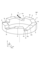
- FIG. 1 is a perspective view showing a configuration of a rotating machine according to a first embodiment
- FIG. 1 is a cross-sectional view showing a configuration of a rotating machine according to a first embodiment, illustrating a radial support force acting on a rotor
- FIG. 1 is a cross-sectional view showing a configuration of a rotating machine according to a first embodiment, for explaining an axial force acting on a rotor
- FIG. 1 is a cross-sectional view showing a configuration of a rotating machine according to a first modified example of the first embodiment
- FIG. 11 is a cross-sectional view showing a configuration of a rotating machine according to a second modification of the first embodiment.
- FIG. 1 is a perspective view showing a configuration of a rotating machine according to a first embodiment
- FIG. 1 is a cross-sectional view showing a configuration of a rotating machine according to a first embodiment, illustrating a radial support force acting on a rotor
- FIG. 1 is a
- FIG. 13 is a perspective view showing a configuration of a rotating machine according to a second embodiment.
- FIG. 11 is a cross-sectional view showing a configuration of a rotating machine according to a third embodiment.
- FIG. 13 is a cross-sectional view showing a configuration of a rotating machine according to a modification of the third embodiment.
- FIG. 13 is a perspective view showing a configuration of a support member for a rotating machine according to a fourth embodiment.
- FIG. 13 is a diagram showing a configuration of a rotor of a rotating machine according to a modification of the fourth embodiment, when the rotor is viewed in the axial direction.
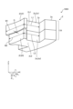
- FIG. 13 is a perspective view showing a configuration of a part of a stator core of a rotating machine according to a fifth embodiment.
- FIG. 13 is a cross-sectional view showing a configuration of a rotating machine according to a fifth embodiment, for explaining an axial force acting on a rotor.
- FIG. 1 is a perspective view showing a configuration of a rotating machine 100 according to a first embodiment.
- the rotating machine 100 is shown cut in half along the axial direction for ease of understanding.
- cross-sectional hatching is omitted.
- the rotating machine 100 includes a rotor 1, a stator 2, and a support member 3.
- the rotating machine 100 includes a frame that houses the rotor 1, the stator 2, and the support member 3, a shaft provided at the center of the rotor 1, and the like.
- the rotor 1 rotates relative to the stator 2 about a rotation axis AX.
- the direction parallel to the rotation axis AX is referred to as the axial direction
- the direction perpendicular to the rotation axis AX is referred to as the radial direction
- the direction of rotation about the rotation axis AX is referred to as the circumferential direction.
- the X-axis, Y-axis, and Z-axis shown in each figure are three axes perpendicular to each other.
- the Z-axis is parallel to the rotation axis AX.
- the direction along the Z-axis (Z-axis direction) is parallel to the axial direction.
- the X-axis and Y-axis are perpendicular to the rotation axis AX.
- the direction along the X-axis is one direction perpendicular to the axial direction and is included in the radial direction.
- the direction along the Y-axis is one direction perpendicular to the axial direction and is included in the radial direction.
- the X-axis direction and the Y-axis direction are not distinguished, they are collectively referred to as the XY-axis direction.
- the rotation direction ⁇ x around the X-axis and the rotation direction ⁇ y around the Y-axis are not distinguished, they are collectively referred to as the tilt direction.
- the direction of the arrow is the positive direction
- the direction opposite to the arrow is the negative direction.
- the case where the direction along the rotation axis AX is parallel to the vertical direction is illustrated.
- the positive direction of the Z axis is the vertically upward direction
- the negative direction of the Z axis is the vertically downward direction.
- the rotor 1 rotates around the rotation axis AX.
- the rotor 1 has a rotor core 1a and multiple permanent magnets 1b.
- the rotor core 1a has a cylindrical shape.
- a through hole 1c extending in the axial direction is formed in the center of the rotor core 1a.
- a shaft (not shown) is placed in the through hole 1c.
- the multiple permanent magnets 1b are arranged on the outer periphery of the rotor core 1a.
- the multiple permanent magnets 1b are arranged at equal angles in the circumferential direction.
- the permanent magnets 1b which are magnetic force generating members, may be fixed to the rotor core 1a by magnetic force, or may be fixed to the rotor core 1a by a fixing member such as an adhesive.
- the permanent magnets 1b are affixed to the surface of the rotor core 1a, but they may also be embedded inside the rotor core 1a.
- the stator 2 is arranged on the outer circumference of the rotor 1, separated from the rotor 1 by a gap 4.
- the stator 2 has a stator core 2a, which is an iron core, and multiple windings 2b.
- the stator core 2a and the windings 2b form an electromagnet, which is a magnetic force generating member.
- the stator core 2a has a cylindrical shape.
- the stator core 2a has a number of teeth 2c arranged in a row in the circumferential direction, and a back yoke portion 2d that connects the teeth 2c at the outer periphery of each tooth 2c.
- the teeth 2c are arranged radially around the rotation axis AX.
- the teeth 2c are arranged at equal angles in the circumferential direction.
- the back yoke portion 2d is formed in a cylindrical shape.
- the winding 2b is wound around each of the multiple teeth 2c.
- the winding 2b generates a magnetic field to rotate the rotor 1 in the circumferential direction.
- the support member 3 is a member that is arranged at least on one side of the rotor 1 in the axial direction along the rotation axis AX, and supports the rotor 1 so as to limit the displacement of the rotor 1 in the axial direction and the tilt direction.
- the axial direction along the rotation axis AX is parallel to the vertical direction, and the support member 3 is arranged vertically below the rotor 1.
- the shape of the support member 3 is cylindrical in this embodiment, but is not particularly limited as long as it can support the rotor 1.
- the shape of the support member 3 is hollow in this embodiment, but may be solid.
- the support member 3 is fixed to a frame (not shown). In FIG.
- the inner diameter of the support member 3 is shown to be smaller than the inner diameter of the rotor 1, but is not limited to the illustrated example.
- the inner diameter of the support member 3 may be larger than the inner diameter of the rotor 1, or the inner diameter of the support member 3 may be the same as the inner diameter of the rotor 1.
- the support member 3 has a support surface 3a that supports the rotor 1.
- the support surface 3a is in circumferential contact with one side of the rotor 1 in the axial direction.
- the support member 3 has a low-friction portion that reduces the frictional force with the rotor 1. Since the material of the support member 3 has a lower friction coefficient than the rotor 1, the low-friction portion may be formed on the whole or part of the support member 3 (the portion of the support member 3 that contacts the rotor 1), or the low-friction portion may be constituted by a lubricant applied to the portion of the support member 3 that contacts the rotor 1.
- An example of a material with a low friction coefficient is Teflon (registered trademark).
- An example of a lubricant is grease.
- the rotor 1 is supported by the support member 3 at a position displaced in the axial direction relative to the stator 2.
- the rotor 1 is supported by the support member 3 at a position sunken vertically downward relative to the stator 2.
- the stator core 2a and the permanent magnet 1b are arranged so that the force of the stator 2 magnetically attracting the rotor 1 restores the axial and tilted displacements of the rotor 1.
- the rotor core 1a and the electromagnets are also arranged so that the force of the stator 2 magnetically attracting the rotor 1 restores the axial and tilted displacements of the rotor 1.
- FIG. 2 is a cross-sectional view showing the configuration of the rotating machine 100 according to the first embodiment, and is a view for explaining the radial supporting force acting on the rotor 1.
- Each cross-sectional view including FIG. 2 is a cross-sectional view along the axial direction.
- the number of poles when the N-pole permanent magnets 1b and the S-pole permanent magnets 1b are arranged alternately in the circumferential direction on the surface of the rotor core 1a is assumed to be p.
- a magnetic field with the number of poles p is generated by passing a current through the winding 2b of the stator 2, that is, by passing a fluctuating current i through the winding 2b of the stator 2.
- the rotor 1 is attracted to the rotation of the magnetic field with the number of poles p and rotates. This generates a torque, which makes it possible to control the rotation speed and angle of the rotor 1.
- an angle at which the density of the magnetic flux 7a increases and an angle at which the density of the magnetic flux 7a decreases are generated in the gap portion 4.
- This difference in density of the magnetic flux 7a generates a radial (XY axis direction) support force that magnetically attracts the rotor 1 radially relative to the stator 2. This allows the rotor 1 to be supported by the stator 2 without contact.
- the rotating machine 100 is a general bearingless motor such as a surface magnet type bearingless motor, when a magnetic field with pole number p ⁇ 2 is generated, as described above, an angle at which the density of the magnetic flux 7a increases and an angle at which the density of the magnetic flux 7a decreases are generated in the gap portion 4, generating a radial support force (XY axis direction).
- the rotating machine 100 is a consequent pole type bearingless motor in which only one of the N poles or S poles, the permanent magnet 1b, is attached between the salient pole rotor core 1a, or a homopolar type bearingless motor in which a salient pole rotor core 1a and a permanent magnet 1b magnetized in the axial direction are used, when a magnetic field with pole number 2 is generated, an angle at which the density of the magnetic flux 7a increases and an angle at which the density of the magnetic flux 7a decreases are generated in the gap portion 4, generating a radial support force (XY axis direction).
- FIG. 3 is a cross-sectional view showing the configuration of the rotating machine 100 according to the first embodiment, and is a diagram for explaining the axial force acting on the rotor 1.
- FIG. 3 shows the case where gravity mg acts on the rotor 1.
- the rotor 1 is displaced vertically downward relative to the stator 2, i.e., in the axial direction, due to gravity mg. As a result, parts of the rotor 1 and stator 2 do not face each other in the radial direction, and magnetic flux 7b is generated that passes diagonally between the rotor 1 and stator 2.
- the rotor 1 is displaced vertically downward relative to the stator 2, so magnetic flux 7b is shown exiting the rotor 1 and entering obliquely the underside of the tip of the teeth 2c of the stator 2.
- the axial displacement of the rotor 1 relative to the stator 2 is z (z ⁇ 0), and the axial rigidity of the rotor 1 is kz.
- the negative sign of the axial stiffness kz of the rotor 1 means that the rotor 1 is attracted to the stator 2 in the direction opposite to the displacement direction of the rotor 1.
- the restoring force f1 is a magnetic force that supports the rotor 1 in the axial direction, and in the illustrated example, it is a force that tries to move the rotor 1 vertically upward.
- the rotor 1 is also supported in the axial direction by the support members 3.
- the restoring force f1 can be increased. This allows the restoring force f1 to support most of the gravity mg, and the remaining component, the supporting force f2, can be reduced.
- the supporting force f2 is also the force with which the rotor 1 is supported in the tilt direction by the supporting member 3. In other words, the supporting force f2 is the force with which the rotor 1 is supported in the axial and tilt directions by the supporting member 3.
- a restoring torque is generated in the opposite direction to the displacement of the rotor 1 in the tilt direction.
- a restoring torque that returns the rotor 1 to the magnetic center in the tilt direction is generated by the magnetic flux 7b that passes obliquely between the rotor 1 and the stator 2.
- the restoring torque increases in proportion to the displacement of the rotor 1 in the tilt direction.
- a passively stable structure can be achieved because the restoring force and restoring torque that return the rotor 1 displaced in the axial and tilt directions to the magnetic center in the axial and tilt directions are generated in the gap portion 4. Since the torque and radial supporting force, the restoring force f1 and the restoring torque are generated in the gap portion 4, the rotating machine 100 can be made smaller and lighter than when the part where the torque and radial supporting force are generated is separated from the part where the restoring force f1 and the restoring torque are generated.
- the stator core 2a and the permanent magnet 1b which is a magnetic force generating member, are arranged so that the force of the stator 2 magnetically attracting the rotor 1 restores the displacement of the rotor 1 in the axial direction and the tilt direction.
- the rotor core 1a and the electromagnet which is a magnetic force generating member, are arranged so that the force of the stator 2 magnetically attracting the rotor 1 restores the displacement of the rotor 1 in the axial direction and the tilt direction.
- the rotating machine 100 is provided with a support member 3 that is arranged on at least one side of the rotor 1 in the axial direction along the rotation axis AX and supports the rotor 1 so as to limit the displacement of the rotor 1 in the axial direction and the tilt direction.
- the support member 3 can support the rotor 1 in the axial direction and the tilt direction. Therefore, further displacement of the rotor 1 in the axial direction and the displacement of the rotor 1 in the tilt direction are suppressed. This makes it possible to suppress vibration of the rotor 1 in the axial direction and the tilt direction.
- the vibration generated in the rotor 1 can be suppressed, and the continuation of the vibration generated in the rotor 1 can also be suppressed.
- there is a frequency at which the rotor 1 is likely to vibrate which is determined by the rigidity of the rotor 1 and the mass and moment of inertia of the rotor 1. Even when the value of this frequency matches the rotation speed of the rotor 1, the vibration of the rotor 1 can be suppressed by avoiding the resonance phenomenon.
- a rotating machine 100 can be obtained that can suppress the vibration of the rotor 1 in the axial and tilt directions while making the structure passively stable with respect to the three degrees of freedom of the rotor 1 in the axial and tilt directions.
- the rotor 1 is supported by the support member 3 at a position displaced in the axial direction relative to the stator 2.
- the restoring force f1 can be increased and the supporting force f2 can be reduced.
- the ratio of the restoring force f1 to the supporting force f2 shown in FIG. 3 may be set to, for example, 9:1 or 19:1, and the supporting force f2 may be set to a value close to 0.
- the wear of the supporting member 3 is reduced, so that the frequency of replacing the supporting member 3 can be reduced and the rotating machine 100 can be operated for a long period of time.
- the torque loss generated by physical contact between the rotor 1 and the supporting member 3 can be reduced, and the operating efficiency of the entire rotating machine 100 can be improved.
- the vibration of the rotor 1 in the axial direction and the tilt direction can be suppressed while maintaining the torque loss and the operating efficiency of the entire rotating machine 100 at approximately the same level.
- the support member 3 is in circumferential contact with the rotor 1.
- the support member 3 supports the rotor 1 around the entire circumference of the rotor 1, so that further displacement of the rotor 1 in the axial direction and displacement of the rotor 1 in the tilt direction can be further suppressed.
- the support member 3 shown in FIG. 3 is provided with a low-friction portion that reduces the frictional force with the rotor 1.
- This configuration reduces the frictional force generated between the rotor 1 and the support member 3, and can achieve the same effect as when the support force f2 described in paragraph 0036 above is reduced.
- the rotor 1 is supported by the support member 3 at a position displaced in the axial direction relative to the stator 2, so that no repulsive magnets are required.
- the stator 2 generates a force that magnetically attracts the rotor 1, and a passively stable structure can be achieved in three degrees of freedom in the axial and tilt directions of the rotor 1, so that no repulsive magnets are required.
- this embodiment can suppress the occurrence of the above problems.
- a method can be considered in which a repulsive magnet is used to repel the rotor 1 vertically downward against the stator 2, and the sum of the gravity mg and the repulsive force is supported by a supporting force f2.
- the supporting force f2 exceeds the gravity mg of the rotor 1. This causes problems such as an increase in frictional heat generated in the support member 3, increased wear of the support member 3, a shortened lifespan of the support member 3, and an increase in torque loss.
- the restoring force f1 generated between the stator 2 and the rotor 1 makes the supporting force f2 smaller than the gravity mg of the rotor 1, thereby suppressing the occurrence of the above problems.
- the rotating machine 100 is an inner rotor type in which the rotor 1 is arranged on the inner circumference of the stator 2, but it may also be an outer rotor type rotating machine 100 in which the rotor 1 is arranged on the outer circumference of the stator 2.
- the rotation axis AX (Z-axis) of the rotor 1 is parallel to the vertical direction, but the entire rotating machine 100 may be tilted with respect to the vertical direction so that there is an angle difference between the rotation axis AX of the rotor 1 and the vertical direction.
- the rotation axis AX of the rotor 1 may be inclined with respect to the vertical direction.
- the support member 3 when the position of the stator 2 in the axial direction is taken as the reference position, the support member 3 only needs to support the rotor 1 at a position where the rotor 1 is displaced from the reference position in the axial direction in the direction of gravity mg acting on the rotor 1 or in the direction in which a reaction force acts on the rotating rotor 1. In this way, the support force f2 generated by the support member 3 is reduced by the burden of the axial restoring force f1 generated between the stator 2 and the rotor 1, compared to when the rotor 1 is supported at a position where it is not displaced in the axial direction from the reference position.
- the rotor 1 has a permanent magnet 1b
- the stator 2 has a stator core 2a, which is an iron core, as an example.
- the rotor 1 may have an iron core
- the stator 2 may have a permanent magnet.
- at least one of the rotor 1 and the stator 2 has an iron core
- at least the other of the rotor 1 and the stator 2 has a permanent magnet.
- the rotating machine 100 has a permanent magnet 1b on the rotor 1, but the rotating machine 100 may not have a permanent magnet 1b on the rotor 1.
- the rotating machine 100 may be modified to become a synchronous reluctance motor in which reluctance, which is the difficulty of magnetic flux passing, changes depending on the rotation angle of the rotor 1, by forming salient poles or slits on the rotor core 1a.
- the rotor 1 is hollow, but it may be solid.
- the hollow space may be used, for example, as a path for wiring or as a flow path for fluid.
- the rotor 1 being hollow can reduce the weight of the entire rotating machine 100.
- the rotor 1 being hollow can dissipate heat into the hollow space when the rotor 1 generates heat, thereby improving the cooling effect of the rotor 1.
- FIG. 2 a configuration is illustrated in which a radial (XY axis direction) supporting force acting on the rotor 1 is generated by placing a permanent magnet 1b on a magnetic circuit in addition to passing a fluctuating current i that contributes to an increase or decrease in the radial (XY axis direction) supporting force through the winding 2b, but this is not limiting.
- a radial (XY axis direction) supporting force acting on the rotor 1 may be generated by passing a bias current I through each winding 2b in addition to passing a fluctuating current i that contributes to an increase or decrease in the radial (XY axis) supporting force through the winding 2b.
- FIG. 4 is a cross-sectional view showing the configuration of a rotating machine 100A according to a first modified example of the first embodiment.
- the rotor 1 shown in FIG. 4 has only the rotor core 1a, and does not have a permanent magnet 1b. There is no reluctance difference in the rotor 1.
- the stator core 2a and the winding 2b form an electromagnet.
- the winding 2b1 is wound around the teeth 2c located in the positive direction of the X-axis.
- the winding 2b2 is wound around the teeth 2c located in the negative direction of the X-axis.
- a current of I+i (A: Ampere), which is the sum of the bias current I and the fluctuating current i, flows through the winding 2b1
- a current of I-i (A: Ampere), which is the difference between the bias current I and the fluctuating current i, flows through the winding 2b2.
- the force acting on the surface of the rotor 1 facing the gap portion 4 located in the positive direction of the X-axis is k(I+i) 2
- the force acting on the surface of the rotor 1 facing the gap portion 4 located in the negative direction of the X-axis is k(I-i) 2
- k is a constant.
- the difference between these two forces is 4 ⁇ k ⁇ I ⁇ i. Therefore, the rotor 1 receives a force of 4 ⁇ k ⁇ I ⁇ i in the positive direction of the X-axis.
- the rotating machine 100A functions as a magnetic bearing that generates a supporting force in the radial direction (X-axis and Y-axis directions).
- the rotor core 1a and the electromagnet which is a magnetic force generating member, are arranged so that the stator 2 magnetically attracts the rotor 1 to restore the displacement of the rotor 1 in the axial and tilt directions.
- the rotor 1 can have three degrees of freedom in the axial and tilt directions, without detecting the position of the rotor 1 and controlling the value of the current, because a restoring force and a restoring torque are generated that cause the rotor 1 displaced in the axial and tilt directions to return to the magnetic center in the axial and tilt directions, making it possible to achieve a passively stable structure.
- the support member 3 can suppress the vibration of the rotor 1 in the axial and tilt directions.
- at least one of the rotor 1 and the stator 2 needs to have an iron core, and at least the other of the rotor 1 and the stator 2 needs to have a magnetic force generating member.
- the rotor 1 may also have both a permanent magnet 1b and an electromagnet as a magnetic force generating member.
- the electromagnet is composed of, for example, a rotor core 1a and a winding wound around the rotor core 1a.
- FIG. 5 is a cross-sectional view showing the configuration of the rotating machine 100B according to a second modified example of the first embodiment.
- FIG. 5 shows a frame 6.
- the frame 6 is shaped like a cylinder with both axial ends open.
- the frame 6 has a peripheral wall portion 6a and an axial end wall 6b.
- the peripheral wall portion 6a is a cylindrical portion extending in the circumferential direction.
- One axial end of the peripheral wall portion 6a is open.
- the other axial end of the peripheral wall portion 6a is closed by the axial end wall 6b.
- the axial end wall 6b has a hole 6c formed therein into which a shaft (not shown) is inserted.
- the stator 2 is fitted and fixed to the inner peripheral surface of the peripheral wall portion 6a of the frame 6.
- the support member 3 is fixed to the axial end wall 6b of the frame 6 via an adjustment member 5.
- the adjustment member 5 is, for example, a screw.
- the adjustment member 5 penetrates the axial end wall 6b of the frame 6 from the outer surface to the inner surface in the axial direction.
- the tip of the adjustment member 5 is inserted into the support member 3.
- the position of the support member 3 in the axial direction is changed by rotating the screw which is the adjustment member 5.
- the position of the support member 3 in the axial direction can be adjusted by rotating the screw, which is the adjustment member 5. Therefore, the position where the support member 3 supports the rotor 1, that is, the axial displacement z of the rotor 1, can be adjusted.
- the value of the supporting force f2 can be changed to the smallest value within a range that is unlikely to cause vibration of the rotor 1 in the axial direction and in the tilt direction.
- the ratio between the restoring force f1 and the supporting force f2 can be quickly and easily changed without disassembling or replacing the entire rotating machine 100B. Therefore, the rotor 1 can be rotated while suppressing the occurrence of vibration of the rotor 1 due to the change in the gravity mg of the entire rotor 1 or the reaction force acting on the rotor 1.
- the adjustment member 5 may be omitted.
- FIG. 6 is a perspective view showing the configuration of the rotating machine 100C according to the second embodiment.
- This embodiment differs from the first embodiment in that the rotating machine 100C includes a plurality of support members 3.
- the same reference numerals are used for parts that overlap with the first embodiment, and description thereof will be omitted.
- Fig. 6 illustrates the rotating machine 100C as viewed from one side in the axial direction.
- the rotating machine 100C has three support members 3.
- the shape of each support member 3 is cylindrical, but is not particularly limited as long as it can support the rotor 1.
- the three support members 3A, 3B, and 3C are arranged at a distance from one another in the circumferential direction.
- the three support members 3A, 3B, and 3C are arranged at equal angles in the circumferential direction.
- the three support members 3A, 3B, and 3C are arranged at 120 degree intervals in the circumferential direction.
- Each of the three support members 3A, 3B, and 3C supports the rotor 1.
- the rotor 1 is supported by the three support members 3A, 3B, and 3C that are arranged at a distance from one another in the circumferential direction.
- the rotor 1 is supported by three support members 3A, 3B, and 3C that are spaced apart from each other in the circumferential direction.
- support forces f21, f22, and f23 are generated at each of the three support members 3A, 3B, and 3C, which are forces that support the rotor 1 in the axial direction and the tilt direction by the support members 3A, 3B, and 3C, respectively. Therefore, further displacement of the rotor 1 in the axial direction and the tilt direction is suppressed. This makes it possible to suppress vibration of the rotor 1 in the axial direction and the tilt direction.
- the points of action of the support forces f21, f22, and f23 are preferably located at equal angles in the circumferential direction, and in this embodiment, they are located at 120 degree intervals in the circumferential direction. In this way, further displacement of the rotor 1 in the axial direction and the displacement of the rotor 1 in the tilt direction can be further suppressed.
- the rotor 1 is supported by three support members 3A, 3B, and 3C that are spaced apart from each other in the circumferential direction.
- This configuration allows each of the support members 3A, 3B, and 3C to be made smaller and lighter than when a single support member 3 is used. Furthermore, when a malfunction occurs in one of the three support members 3A, 3B, and 3C, only the malfunctioning one needs to be replaced, reducing the cost of replacement.
- the number of support members 3 is three, but four or more may be used. That is, the rotor 1 in this embodiment may be supported by three or more support members 3 spaced apart from each other in the circumferential direction. If there is variation in the position of the support members 3 in the axial direction, for example, a phenomenon may occur in which three of the four or more support members 3 support the rotor 1 and the remaining support members 3 do not support the rotor 1. Even if any of the support members 3 supporting the rotor 1 loses its support function due to wear or damage, if there are four or more support members 3, three or more support members 3, including the support member 3 that did not support the rotor 1, will newly support the rotor 1. This ensures redundancy of the support members 3 and increases the reliability of the rotating machine 100C.
- each of the three support members 3A, 3B, and 3C may have a low-friction portion that reduces the frictional force with the rotor 1. In this way, the frictional force generated between the rotor 1 and the support members 3 can be reduced, and the same effect as that achieved by reducing the support force f2 described in paragraph 0036 above can be achieved.
- FIG. 7 is a cross-sectional view showing the configuration of a rotating machine 100D according to the third embodiment.
- This embodiment differs from the first and second embodiments in that the support member 3 functions as a hydrostatic bearing that supports the rotor 1.
- the same reference numerals are used for parts that overlap with the first and second embodiments, and descriptions thereof will be omitted.
- the support member 3 is a single member. Inside the support member 3, a flow path 3b is formed through which the fluid flows. Reference numeral 8 in FIG. 7 shows a schematic representation of the flow of the fluid.
- the fluid may be a gas or a liquid.
- An example of the gas is air.
- An example of the liquid is water or oil.
- the shape of the support member 3 is, for example, a hollow disk shape, but is not particularly limited as long as the fluid can flow out toward the rotor 1.
- An inlet 3f is formed on the outer peripheral surface 3c of the support member 3 for allowing the fluid to flow into the flow path 3b.
- An outlet 3g is formed on the surface 3d of the support member 3 facing the rotor 1 for allowing the fluid to flow out from the flow path 3b toward the rotor 1.
- the outlet 3g has a circular shape extending in the circumferential direction.
- the fluid flowing out from the outlet 3g toward the rotor 1 supports the rotor 1 in the axial direction and in the tilt direction.
- the fluid flowing out from the outlet 3g toward the rotor 1 supports the rotor 1 in a circumferential shape.
- the support member 3 functions as a hydrostatic bearing that supports the rotor 1.
- a flow path 3b through which the fluid flows is formed inside the support member 3, and an outlet 3g is formed on the surface 3d of the support member 3 facing the rotor 1 to allow the fluid to flow out from the flow path 3b toward the rotor 1.
- the rotor 1 is displaced vertically downward relative to the stator 2, and is supported by the support member 3 at a position where the rotor 1 is sunk vertically downward relative to the stator 2.
- a restoring force f1 is generated by the axial displacement z of the rotor 1, and the support force f2 can be reduced.
- This makes it possible to reduce the flow rate and pressure of the fluid flowing out from the outlet 3g toward the rotor 1.
- This makes it possible to reduce the input energy required to prepare the fluid to flow from the inlet 3f into the flow path 3b of the support member 3, and also to reduce the torque loss that occurs due to physical contact between the rotor 1 and the support member 3.
- FIG. 8 is a cross-sectional view showing the configuration of the rotating machine 100E according to a modified example of the third embodiment.
- FIG. 8 shows two support members 3, in reality, the rotating machine 100E includes three support members 3.
- FIG. 8 shows support forces f21 and f22, which are forces by which the rotor 1 is supported in the axial direction and in the tilt direction by each of the two support members 3A and 3B, but in reality, a support force f23 (not shown) is also generated by which the rotor 1 is supported in the axial direction and in the tilt direction by the remaining support member 3 (not shown).
- the three support members 3 are arranged at a distance from each other in the circumferential direction.
- the three support members 3 are arranged at equal angles in the circumferential direction.
- the three support members 3 are arranged at 120 degree intervals in the circumferential direction.
- a flow path 3b through which the fluid flows is formed inside each of the three support members 3.
- the shape of each support member 3 is, for example, a hollow cylinder, but is not particularly limited as long as the fluid can flow out toward the rotor 1.
- An inlet 3f is formed on the surface 3e of each support member 3 facing away from the rotor 1 to allow the fluid to flow into the flow path 3b.
- An outlet 3g is formed on the surface 3d of each support member 3 facing the rotor 1 to allow the fluid to flow out from the flow path 3b toward the rotor 1.
- the fluid flowing out from each outlet 3g of the three support members 3 toward the rotor 1 supports the rotor 1 in the axial direction and in the tilt direction.
- each support member 3 also functions as a hydrostatic bearing that supports the rotor 1.
- This modified example can achieve the same effect as the third embodiment.
- the number of support members 3 is three, but it may be four or more.
- the rotor 1 of this modified example only needs to be supported by the fluid flowing out from the respective outlets 3g of three or more support members 3 spaced apart from each other in the circumferential direction.
- FIG. 9 is a perspective view showing a configuration of a support member 3 of a rotating machine 100F according to the fourth embodiment.
- This embodiment differs from the first embodiment in that the support member 3 functions as a dynamic pressure bearing that supports the rotor 1.
- the same reference numerals are used for parts that overlap with the first embodiment, and description thereof will be omitted.
- a surface 3d of the support member 3 facing the rotor 1 is formed with a plurality of grooves 3h that open toward the rotor 1.
- the grooves 3h are arranged at a distance from each other in the circumferential direction.
- the grooves 3h are arranged at equal angles in the circumferential direction.
- the number of grooves 3h is five in this embodiment, but is not particularly limited.
- the grooves 3h are recessed toward the side opposite to the side where the rotor 1 is located in the axial direction.
- a flat portion 3i is formed between adjacent grooves 3h in the circumferential direction.
- the flat portion 3i is a flat portion perpendicular to the axial direction.
- the flat portion 3i is arranged closer to the rotor 1 in the axial direction than the grooves 3h.
- the grooves 3h and the flat portions 3i are arranged alternately in the circumferential direction.
- the groove 3h has a first groove surface 3h1, a second groove surface 3h2, and a third groove surface 3h3.
- the first groove surface 3h1 is a surface extending in the axial direction.
- the first groove surface 3h1 is continuous with one of the two flat portions 3i adjacent to the groove 3h.
- the first groove surface 3h1 extends in the axial direction away from one of the flat portions 3i.
- the second groove surface 3h2 is a surface extending in the circumferential direction.
- the second groove surface 3h2 extends in the circumferential direction from an end of the first groove surface 3h1 opposite to the end that is continuous with one of the flat portions 3i.
- the third groove surface 3h3 is an inclined surface that inclines toward the rotor 1 as it extends in the circumferential direction away from the second groove surface 3h2.
- the third groove surface 3h3 is inclined with respect to the axial direction.
- the third groove surface 3h3 extends in the circumferential direction from the end of the second groove surface 3h2 opposite the end that continues to the first groove surface 3h1.
- the end of the third groove surface 3h3 opposite the end that continues to the second groove surface 3h2 continues to the other of the two flat portions 3i adjacent to the groove 3h.
- a groove 3h that opens toward the rotor 1 is formed on the surface 3d of the support member 3 facing the rotor 1.
- the groove 3h preferably has a third groove surface 3h3 that is an inclined surface inclined with respect to the axial direction. In this way, when the rotor 1 rotates, the three-dimensional inclination of the groove 3h eliminates the passage of the fluid, making it easier for the fluid to flow from the support member 3 toward the rotor 1.
- a portion of the gravity mg acting on the rotor 1 is supported by the restoring force f1, so the remaining portion of the gravity mg of the rotor 1 can be supported by the pressure of the fluid flowing from the support member 3 toward the rotor 1.
- the inclination of the three-dimensional groove 3h can be reduced to design the device so as to reduce the pressure of the fluid flowing from the support member 3 toward the rotor 1. This can reduce the input energy of the fluid, thereby improving the operating efficiency of the entire rotating machine 100F.
- FIG. 10 is a diagram showing the configuration of the rotor 1 of a rotating machine 100G according to a modified example of the fourth embodiment, and is a diagram showing the rotor 1 as viewed along the axial direction.
- grooves 1e are hatched with dots for ease of understanding.
- a plurality of grooves 1e that open toward the support member 3 are formed on the surface 1d of the rotor 1 facing the support member 3 (not shown).
- the plurality of grooves 1e are arranged apart from each other in the circumferential direction.
- the plurality of grooves 1e are arranged at equal angles in the circumferential direction.
- the number of grooves 1e is nine in this embodiment, but is not particularly limited.
- the grooves 1e are recessed toward the side opposite to the side where the support member 3 exists in the axial direction.
- Flat portions 1f are formed between adjacent grooves 1e in the circumferential direction.
- the flat portions 1f are flat portions that are perpendicular to the axial direction.
- the flat portions 1f are arranged closer to the support member 3 in the axial direction than the grooves 1e.
- the grooves 1e and the flat portions 1f are arranged alternately in the circumferential direction.
- Each groove 1e extends in the radial direction and is formed from the outer peripheral surface to the inner peripheral surface of the rotor 1.
- Each groove 1e extends while bending so as to be positioned on one side of the circumferential direction as it moves from the outer side to the inner side in the radial direction.
- the extension direction of each groove 1e is projected onto a plane normal to the rotation axis AX of the rotor 1, the extension direction of each groove 1e is positioned at a position offset from the rotation axis AX of the rotor 1.
- the openings 1g of each groove 1e that open onto the outer peripheral surface of the rotor 1 are arranged at equal angles apart in the circumferential direction.
- the openings 1h of each groove 1e that open onto the inner peripheral surface of the rotor 1 are arranged at equal angles apart in the circumferential direction.
- the openings 1g and 1h in each groove 1e are offset from each other in the circumferential direction.
- the groove width D of each groove 1e narrows as it moves from the outer side to the inner side in the radial direction. In other words, the groove width D of each groove 1e is wider as it moves radially outward and narrower as it moves radially inward.
- the support member 3 does not function as a dynamic pressure bearing that supports the rotor 1, but when the rotor 1 is rotating and the rotation speed of the rotor 1 exceeds a certain threshold, the support member 3 functions as a dynamic pressure bearing that supports the rotor 1.
- a groove 3h having the same shape as the groove 1e shown in FIG. 10 may be formed on the surface 3d of the support member 3 facing the rotor 1 shown in FIG. 9, or a groove 1e having the same shape as the groove 3h shown in FIG. 9 may be formed on the surface 1d of the rotor 1 facing the support member 3 shown in FIG. 10.
- the grooves 3h, 1e that open toward the other side are formed on either the surface 3d of the support member 3 facing the rotor 1 or the surface 1d of the rotor 1 facing the support member 3.
- Fig. 11 is a perspective view showing a configuration of a part of a stator core 2a of the rotating machine 100H according to the fifth embodiment.
- Fig. 12 is a cross-sectional view showing the configuration of the rotating machine 100H according to the fifth embodiment, and is a diagram for explaining the axial force acting on the rotor 1.
- This embodiment differs from the first embodiment in that the permeance decreases in one direction from one side to the other in the axial direction.
- the same reference numerals are used for parts that overlap with the first embodiment, and the description thereof will be omitted.
- each tooth 2c has multiple tooth body portions 2e that protrude radially inward from the back yoke portion 2d, and multiple tooth tip portions 2f that protrude in both circumferential directions from the tip of each tooth body portion 2e.
- the shape of the tooth tip portions 2f is brim-like and wider than the circumferential width of the tooth body portion 2e. This allows a large amount of magnetic flux 7c, 7d to pass between the stator 2 and rotor 1 shown in Figure 12.
- the dashed line in Figure 12 diagrammatically indicates the boundary between the teeth 2c and the back yoke portion 2d.
- the number of tooth body parts 2e and the number of tooth tip parts 2f in each tooth 2c are not particularly limited, but in this embodiment, they are two each.
- the two tooth body parts 2e are stacked in the axial direction.
- the two tooth tip parts 2f are stacked in the axial direction.
- the tooth body part 2e and the tooth tip part 2f arranged on one side of the axial direction are referred to as the first tooth body part 2e1 and the first tooth tip part 2f1, respectively, and the first tooth body part 2e1 and the first tooth tip part 2f1 are collectively referred to as the first tooth part 2c1.
- the tooth body part 2e and the tooth tip part 2f arranged on the other side of the axial direction are referred to as the second tooth body part 2e2 and the second tooth tip part 2f2, respectively, and the second tooth body part 2e2 and the second tooth tip part 2f2 are collectively referred to as the second tooth part 2c2.
- the first teeth 2c1 are positioned vertically above the second teeth 2c2.
- the circumferential width W1 of the first tooth tip 2f1 is wider than the circumferential width W2 of the second tooth tip 2f2.
- the circumferential width of the tooth tip 2f narrows in one direction from one side of the axial direction where the first tooth tip 2f1 exists to the other side of the axial direction where the second tooth tip 2f2 exists.
- the radial length L1 of the first tooth portion 2c1 is longer than the radial length L2 of the second tooth portion 2c2.
- the radial length of the tooth 2c shortens in one direction from one side of the axial direction where the first tooth portion 2c1 exists to the other side of the axial direction where the second tooth portion 2c2 exists.
- a tooth length difference G which is the difference between the radial length L1 of the first tooth portion 2c1 and the radial length L2 of the second tooth portion 2c2, is generated in the tooth 2c.
- Permeance means an amount that represents the ease with which magnetic flux 7c, 7d passes through at least one of the gap portion 4 and the stator core 2a, which is an iron core, in a magnetic path that circulates around the stator 2 and the rotor 1 in the radial and circumferential directions.
- magnetic flux passes through iron more easily than through air, so if the magnetic path is an iron core, the permeance is large. Also, the permeance increases as the width of the magnetic path increases, and increases as the magnetic path length of the air is shorter and the magnetic path length of the iron core is longer.
- the circumferential width W1 of the first teeth tip portion 2f1 is wider than the circumferential width W2 of the second teeth tip portion 2f2, and the radial length L1 of the first teeth portion 2c1 is longer than the radial length L2 of the second teeth portion 2c2. Therefore, the permeance of the second teeth portion 2c2 is smaller than that of the first teeth portion 2c1.
- the permeance which is a quantity that indicates the ease with which magnetic flux 7c, 7d passes through at least one of the gap portion 4 and the stator core 2a, which is an iron core, in the magnetic path that circles the stator 2 and rotor 1 in the radial and circumferential directions, decreases in one direction from one side in the axial direction to the other.
- Figure 12 shows the case where gravity mg acts on rotor 1.
- the force that supports the gravity mg acting on the rotor 1 is the sum of the restoring force f1, which is the force with which the stator 2 magnetically attracts the rotor 1, and the supporting force f2, which is the force with which the rotor 1 is supported in the axial direction by the support member 3.
- the restoring force f1 includes a restoring force f12 generated by the magnetic flux 7d.
- the restoring force f1 also includes the restoring force f11 generated by the magnetic flux 7c.
- the restoring force f1 is generated at a plurality of axial positions of the stator 2, and is the sum of the restoring forces f11 and f12.
- the permeance which is a quantity that indicates the ease with which the magnetic flux 7c, 7d passes through at least one of the gap portion 4 and the stator core 2a, which is an iron core, in the magnetic path that circles the stator 2 and the rotor 1 in the radial and circumferential directions, decreases in one direction from one side in the axial direction to the other.
- the restoring force f1 can be increased in one direction from the other side in the axial direction to one side. This makes it possible to further reduce the frictional heat generated between the rotor 1 and the support member 3, and to reduce the torque loss that occurs when the support member 3 physically contacts the rotor 1. This makes it possible to further extend the life of the support member 3 and further improve the operating efficiency of the entire rotating machine 100H.
- the generation of restoring force f11 means that, when supporting force f2 is constant, the axial displacement z of rotor 1 can be brought closer to 0.
- the area in which rotor 1 and stator 2 face each other in the radial direction increases, and the supporting force and torque in the radial direction (XY axis directions) increase. This reduces the current required to generate the same supporting force and torque in the radial direction (XY axis directions), improving the operating efficiency of the entire rotating machine 100H.
- first teeth portion 2c1 and the second teeth portion 2c2 the case where both the circumferential width and radial length are changed in the first teeth portion 2c1 and the second teeth portion 2c2 is illustrated, but only one of them may be changed. Also, in this embodiment, the case where the circumferential width and radial length are changed in two teeth portions, the first teeth portion 2c1 and the second teeth portion 2c2 is illustrated, but only one of the circumferential width and radial length may be changed in three or more teeth portions.
- the support member 3 of this embodiment may be modified to function as a hydrostatic bearing supporting the rotor 1 as in the above-described embodiment 3, or may be modified to function as a hydrodynamic bearing supporting the rotor 1 as in the above-described embodiment 4.
- the fluid pressure required when the support member 3 functions as a hydrostatic bearing or a hydrodynamic bearing can be further reduced.
Landscapes
- Engineering & Computer Science (AREA)
- Power Engineering (AREA)
- Connection Of Motors, Electrical Generators, Mechanical Devices, And The Like (AREA)
- Iron Core Of Rotating Electric Machines (AREA)
Priority Applications (3)
| Application Number | Priority Date | Filing Date | Title |
|---|---|---|---|
| JP2024529226A JP7595813B1 (ja) | 2023-12-15 | 2023-12-15 | 回転機 |
| PCT/JP2023/045095 WO2025126474A1 (ja) | 2023-12-15 | 2023-12-15 | 回転機 |
| CN202380099788.3A CN121399833A (zh) | 2023-12-15 | 2023-12-15 | 旋转机 |
Applications Claiming Priority (1)
| Application Number | Priority Date | Filing Date | Title |
|---|---|---|---|
| PCT/JP2023/045095 WO2025126474A1 (ja) | 2023-12-15 | 2023-12-15 | 回転機 |
Publications (1)
| Publication Number | Publication Date |
|---|---|
| WO2025126474A1 true WO2025126474A1 (ja) | 2025-06-19 |
Family
ID=93705892
Family Applications (1)
| Application Number | Title | Priority Date | Filing Date |
|---|---|---|---|
| PCT/JP2023/045095 Pending WO2025126474A1 (ja) | 2023-12-15 | 2023-12-15 | 回転機 |
Country Status (3)
| Country | Link |
|---|---|
| JP (1) | JP7595813B1 (https=) |
| CN (1) | CN121399833A (https=) |
| WO (1) | WO2025126474A1 (https=) |
Citations (8)
| Publication number | Priority date | Publication date | Assignee | Title |
|---|---|---|---|---|
| JPS59126569U (ja) * | 1983-02-15 | 1984-08-25 | 松下電器産業株式会社 | 小型電動機 |
| JPH04325854A (ja) * | 1991-04-26 | 1992-11-16 | Hitachi Ltd | ポリゴンミラーモートル |
| JPH08172746A (ja) * | 1994-12-20 | 1996-07-02 | Kanegafuchi Chem Ind Co Ltd | 樹脂製スラスト受け及びそれを用いた減速機付電動機 |
| JP2001347227A (ja) * | 2000-06-06 | 2001-12-18 | Noriyuki Enomoto | 振動器 |
| JP2011055640A (ja) * | 2009-09-02 | 2011-03-17 | Toshiba Mitsubishi-Electric Industrial System Corp | 立形回転電機 |
| JP2014036490A (ja) * | 2012-08-08 | 2014-02-24 | Daikin Ind Ltd | アキシャルギャップ型回転電機及び回転電機駆動装置 |
| JP2016163495A (ja) * | 2015-03-04 | 2016-09-05 | 国立大学法人東京工業大学 | 電動機および電動機システム |
| JP2022156615A (ja) * | 2021-03-31 | 2022-10-14 | ダイキン工業株式会社 | 電動機、圧縮機、及び冷凍装置 |
-
2023
- 2023-12-15 JP JP2024529226A patent/JP7595813B1/ja active Active
- 2023-12-15 WO PCT/JP2023/045095 patent/WO2025126474A1/ja active Pending
- 2023-12-15 CN CN202380099788.3A patent/CN121399833A/zh active Pending
Patent Citations (8)
| Publication number | Priority date | Publication date | Assignee | Title |
|---|---|---|---|---|
| JPS59126569U (ja) * | 1983-02-15 | 1984-08-25 | 松下電器産業株式会社 | 小型電動機 |
| JPH04325854A (ja) * | 1991-04-26 | 1992-11-16 | Hitachi Ltd | ポリゴンミラーモートル |
| JPH08172746A (ja) * | 1994-12-20 | 1996-07-02 | Kanegafuchi Chem Ind Co Ltd | 樹脂製スラスト受け及びそれを用いた減速機付電動機 |
| JP2001347227A (ja) * | 2000-06-06 | 2001-12-18 | Noriyuki Enomoto | 振動器 |
| JP2011055640A (ja) * | 2009-09-02 | 2011-03-17 | Toshiba Mitsubishi-Electric Industrial System Corp | 立形回転電機 |
| JP2014036490A (ja) * | 2012-08-08 | 2014-02-24 | Daikin Ind Ltd | アキシャルギャップ型回転電機及び回転電機駆動装置 |
| JP2016163495A (ja) * | 2015-03-04 | 2016-09-05 | 国立大学法人東京工業大学 | 電動機および電動機システム |
| JP2022156615A (ja) * | 2021-03-31 | 2022-10-14 | ダイキン工業株式会社 | 電動機、圧縮機、及び冷凍装置 |
Also Published As
| Publication number | Publication date |
|---|---|
| CN121399833A (zh) | 2026-01-23 |
| JPWO2025126474A1 (https=) | 2025-06-19 |
| JP7595813B1 (ja) | 2024-12-06 |
Similar Documents
| Publication | Publication Date | Title |
|---|---|---|
| JP7291971B2 (ja) | 磁気浮上軸受の剛性増強機構、磁気浮上軸受、及び血液ポンプ | |
| EP0191225B1 (en) | Magnetic bearing device | |
| JP2644374B2 (ja) | 磁気軸受構造体 | |
| US8058758B2 (en) | Apparatus for magnetic bearing of rotor shaft with radial guidance and axial control | |
| US20100127589A1 (en) | Bearing device having a shaft which is mounted magnetically such that it can rotate about an axis with respect to a stator, and having a damping apparatus | |
| JPWO2009093428A1 (ja) | ベアリングレスモータ | |
| US9765815B2 (en) | Method and apparatus for hybrid suspension system | |
| JPS5993992A (ja) | 軸流分子ポンプ | |
| JP3057047B2 (ja) | 磁気懸架装置 | |
| US20180283493A1 (en) | Dynamic force generator comprising at least two unbalanced masses and actuator comprising said generators | |
| US20100201216A1 (en) | Bearing device for non-contacting bearing of a rotor with respect to a stator | |
| JP2003199288A (ja) | 磁気浮上モータ、及び磁気軸受装置 | |
| KR100701550B1 (ko) | 베어링리스 스텝모터 | |
| JP7595813B1 (ja) | 回転機 | |
| JP2010041742A (ja) | アキシャル磁気浮上回転モータ及びアキシャル磁気浮上回転モータを用いたターボ形ポンプ | |
| US8110955B2 (en) | Magnetic bearing device of a rotor shaft against a stator with rotor disc elements, which engage inside one another, and stator disc elements | |
| KR100426616B1 (ko) | 베어링리스 리니어 모터 | |
| CN119298513A (zh) | 磁力支撑轴承电机 | |
| JP4320420B2 (ja) | 磁気軸受およびそれを備えた軸受装置 | |
| JPH08296645A (ja) | 磁気軸受装置 | |
| JP2004316756A (ja) | 5軸制御磁気軸受 | |
| KR100595823B1 (ko) | 로렌츠력을 이용한 전자기 베어링 | |
| JP4528974B2 (ja) | 振動抑制装置 | |
| WO2023163153A1 (ja) | 磁気浮上式電動機および磁気浮上式ポンプ | |
| JP3186600U (ja) | 磁気浮上式ファン |
Legal Events
| Date | Code | Title | Description |
|---|---|---|---|
| ENP | Entry into the national phase |
Ref document number: 2024529226 Country of ref document: JP Kind code of ref document: A |
|
| WWE | Wipo information: entry into national phase |
Ref document number: 2024529226 Country of ref document: JP |
|
| 121 | Ep: the epo has been informed by wipo that ep was designated in this application |
Ref document number: 23961536 Country of ref document: EP Kind code of ref document: A1 |