WO2025115488A1 - 基板処理装置および基板搬送方法 - Google Patents
基板処理装置および基板搬送方法 Download PDFInfo
- Publication number
- WO2025115488A1 WO2025115488A1 PCT/JP2024/038378 JP2024038378W WO2025115488A1 WO 2025115488 A1 WO2025115488 A1 WO 2025115488A1 JP 2024038378 W JP2024038378 W JP 2024038378W WO 2025115488 A1 WO2025115488 A1 WO 2025115488A1
- Authority
- WO
- WIPO (PCT)
- Prior art keywords
- substrate
- standard
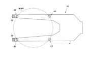
- carrier
- distance sensors
- teaching
- Prior art date
- Legal status (The legal status is an assumption and is not a legal conclusion. Google has not performed a legal analysis and makes no representation as to the accuracy of the status listed.)
- Pending
Links
Images











Classifications
-
- B—PERFORMING OPERATIONS; TRANSPORTING
- B25—HAND TOOLS; PORTABLE POWER-DRIVEN TOOLS; MANIPULATORS
- B25J—MANIPULATORS; CHAMBERS PROVIDED WITH MANIPULATION DEVICES
- B25J13/00—Controls for manipulators
- B25J13/08—Controls for manipulators by means of sensing devices, e.g. viewing or touching devices
-
- H—ELECTRICITY
- H10—SEMICONDUCTOR DEVICES; ELECTRIC SOLID-STATE DEVICES NOT OTHERWISE PROVIDED FOR
- H10P—GENERIC PROCESSES OR APPARATUS FOR THE MANUFACTURE OR TREATMENT OF DEVICES COVERED BY CLASS H10
- H10P72/00—Handling or holding of wafers, substrates or devices during manufacture or treatment thereof
- H10P72/30—Handling or holding of wafers, substrates or devices during manufacture or treatment thereof for conveying, e.g. between different workstations
Definitions
- the present invention relates to a substrate processing apparatus and a substrate transport method for processing substrates.
- substrates include semiconductor substrates, substrates for FPDs (Flat Panel Displays), glass substrates for photomasks, substrates for optical disks, substrates for magnetic disks, ceramic substrates, and substrates for solar cells.
- FPDs include liquid crystal display devices and organic EL (electroluminescence) display devices.
- mapping sensors transmissive sensors
- the two sets of mapping sensors are moved downward. This allows two heights of the substrate at the two different positions to be detected. Based on these two heights of the substrate, the differential height of the tilted substrate and the amount of substrate positional deviation toward the back of the carrier are detected (see, for example, Patent Document 1).
- Patent Document 2 discloses a substrate transport device equipped with a detection unit, which is a mechanism for detecting the position, shape, etc. of each substrate stored in a storage unit (carrier).
- the detection unit is equipped with three distance sensors that use infrared rays, ultrasonic waves, etc.
- the substrate transport robot removes substrates from the carrier placed on the carrier placement section. At this time, if there is an error in the shape of the carrier, for example, the hand of the substrate transport robot will only move to pre-registered positions, which may result in transport problems such as failing to pick up the substrate.
- Patent Document 1 the amount of misalignment of the substrate toward the rear of the carrier is detected. However, it is not possible to detect the amount of misalignment of the substrate in the horizontal direction perpendicular to the direction in which the substrate is inserted and removed from the carrier.
- the present invention was made in consideration of these circumstances, and aims to provide a substrate processing apparatus and a substrate transport method that can prevent substrate transport problems even if the substrate is misaligned in the horizontal plane.
- the substrate processing apparatus comprises a carrier placement section for placing a processing carrier having a plurality of slots for storing a plurality of substrates in a horizontal position arranged vertically and a carrier opening for inserting and removing the plurality of substrates, a substrate transport robot having a hand for supporting one substrate and capable of moving the hand, two distance sensors arranged horizontally so as to face the plurality of substrates in the processing carrier via the carrier opening, a sensor lifting section for moving the two distance sensors vertically, and a control section, the control section being configured to: The two distance sensors are moved in the vertical direction by the sensor lifting unit, and while the two distance sensors are moving, the two distance sensors measure two distances between the two distance sensors and two different points on the periphery of each substrate stored in the processing carrier placed on the carrier placement unit, and the center position of each substrate in a horizontal plane is calculated based on the two distances corresponding to each substrate and the diameter of each substrate, and the substrate
- the substrate processing apparatus includes two distance sensors arranged horizontally to face multiple substrates in a processing carrier through the carrier opening.
- the control unit measures two distances to two different points on the periphery of each substrate in the processing carrier placed on the carrier placement unit, using the two distance sensors while the two distance sensors are moving.
- the control unit also calculates the center position of each substrate in the horizontal plane from the two distances for each substrate and the diameter of each substrate. The calculated center position in the horizontal plane indicates the exact position of the substrate. Therefore, even if the substrate is misaligned in the horizontal plane, problems with substrate transport by the substrate transport robot can be prevented.
- the control unit executes a teaching process and a teaching correction process, and as the teaching process, the control unit causes the substrate transport robot to move the hand into a standard carrier placed on the carrier placement unit, sets a position for the hand to pick up a standard substrate stored in a predetermined standard slot among a plurality of standard slots of the standard carrier as a teaching position, moves the two distance sensors in the vertical direction to a height position corresponding to the standard substrate stored in the standard slot by the sensor lift unit, measures two standard distances between the two distance sensors and two different points on the periphery of the standard substrate stored in the standard slot, calculates a standard center position in the horizontal plane of the standard substrate based on the two standard distances and the diameter of the standard substrate, and associates the standard center position with the teaching position, and then executes the following:
- the teaching correction process preferably involves moving the two distance sensors vertically using the sensor lifting unit, measuring two distances between the two distance sensors and two different points
- the position for picking up a standard substrate stored in a specified standard slot of the standard carrier with a hand is set as a teaching position.
- two standard distances to the standard substrate are measured by two distance sensors.
- the standard center position is then calculated based on the two standard distances and the diameter of the standard substrate.
- the standard center position is associated with the teaching position.
- the amount of positional deviation of the center position of the substrate stored in the slot of the processing carrier corresponding to the standard slot is calculated based on the standard center position.
- the teaching position is corrected using the calculated amount of positional deviation. Therefore, the teaching position in the horizontal plane can be corrected well.
- control unit performs the teaching process for all of the multiple standard slots of the standard carrier, and performs the teaching correction process for all of the multiple slots of the processing carrier. This allows the teaching positions in the horizontal plane to be properly corrected for all of the multiple substrates in the processing carrier.
- control unit performs the teaching process for the first standard slot at the bottom and the second standard slot at the top of the multiple standard slots of the standard carrier, and as the teaching process for a third standard slot between the first and second standard slots of the multiple standard slots, calculates a third teaching position for the third standard slot from the geometric relationship between the first teaching position for the first standard slot and the second teaching position for the second standard slot, calculates a third standard center position for the third standard slot from the geometric relationship between the first standard center position for the first standard slot and the second standard center position for the second standard slot, associates the third standard center position with the third teaching position, and performs the teaching correction process for all of the multiple slots of the processing carrier.
- the teaching process is performed for the first standard slot at the bottom row and the second standard slot at the top row of the standard carrier, and the third standard slot between them is calculated from a geometric relationship. This makes it easy to perform the teaching process.
- the substrate transport robot has two or more hands including the hand, each of which supports one substrate, and can move the two or more hands as a unit; when the two or more hands support two or more substrates among the plurality of substrates, the control unit preferably calculates an average value of the two or more central positions in the horizontal plane corresponding to the two or more substrates, and transports the two or more substrates from the processing carrier by the substrate transport robot based on the average value.
- the average of two or more center positions corresponding to two or more substrates supported by the two or more hands is calculated, and two or more substrates are transported based on this average value. Therefore, even if the substrates are misaligned in the horizontal plane, problems with the substrate transport robot can be prevented.
- the above-mentioned substrate processing apparatus preferably further comprises an alarm unit that emits at least one of sound and light, and the control unit preferably causes the alarm unit to emit at least one of sound and light when the amount of positional deviation exceeds a preset range. This allows the operator to recognize that the amount of positional deviation has exceeded the preset range.
- the substrate transport method of the present invention is a substrate transport method for a substrate processing apparatus including a carrier mounting section for mounting a processing carrier having a plurality of slots for storing a plurality of substrates in a horizontal position arranged in a vertical direction and a carrier opening for inserting and removing the plurality of substrates, a substrate transport robot having a hand for supporting one substrate and capable of moving the hand, two distance sensors arranged horizontally so as to face the plurality of substrates in the processing carrier via the carrier opening, and a sensor lifting section for moving the two distance sensors in a vertical direction, wherein the two distance sensors are detected by the sensor lifting section.
- the method is characterized by comprising a sensor moving step of moving the distance sensor in the vertical direction, a distance measuring step of measuring, while the two distance sensors are moving, two distances between the two distance sensors and two different points on the periphery of each substrate stored in the processing carrier placed on the carrier placement section, a center position calculating step of calculating the center position of each substrate in a horizontal plane based on the two distances corresponding to each substrate and the diameter of each substrate, and a transport step of transporting the substrates from the processing carrier by the substrate transport robot based on the center position of each substrate in the horizontal plane.
- the substrate processing apparatus and substrate transport method according to the present invention can prevent problems with substrate transport even if the substrate is misaligned in the horizontal plane.
- FIG. 1 is a plan view showing a schematic configuration of a substrate processing apparatus according to a first embodiment
- FIG. FIG. 2 is a vertical cross-sectional view mainly showing an indexer block of the substrate processing apparatus according to the first embodiment.
- FIG. FIG. FIG. 4 is a plan view showing two distance sensors positioned at standby positions.
- FIG. 2 is a plan view showing two distance sensors positioned at measurement positions.
- FIG. 2 is a plan view showing two distance sensors and a substrate.
- FIG. 2 is a side view of the substrate transport robot.
- FIG. 2 is a block diagram showing a control configuration of the substrate processing apparatus; 4 is a flowchart showing an operation of the substrate processing apparatus.
- 13A to 13C are diagrams for explaining the operation for acquiring the teaching position of the standard board stored in the first slot.
- FIG. 13A to 13C are diagrams for explaining the operation for acquiring the teaching position of the standard board stored in the first slot.
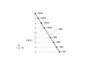
- FIG. 13 is a diagram for explaining calculation of the teaching positions of the Z component for the second to twenty-fourth slots.
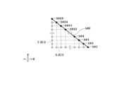
- FIG. 13 is a diagram for explaining calculation of teaching positions of the X and Y components for the second to twenty-fourth slots.
- FIG. 11 is a vertical cross-sectional view for explaining measurements by two distance sensors for calculating a standard center position.
- FIG. 13 is a diagram for explaining calculation of the standard center position of the Z component for the second to twenty-fourth slots.
- FIG. 13 is a diagram for explaining calculation of standard center positions of the X and Y components for the second to twenty-fourth slots.
- FIG. 11 is a vertical cross-sectional view for explaining measurements by two distance sensors for calculating the center position.
- FIG. 13 is a plan view for explaining correction of a teaching position.
- FIG. 11 is a vertical cross-sectional view mainly showing an indexer block of a substrate processing apparatus according to a second embodiment.
- FIG. 11 is a side view of a substrate transport robot having two or more hands according to a third embodiment.
- FIG. 13 is a diagram showing two distance sensors provided on a hand according to a modified example.
- FIG. 13 is a plan view showing a sensor moving section that swings two distance sensors according to a modified example.
- Fig. 1 is a plan view showing a schematic configuration of a substrate processing apparatus according to the first embodiment.
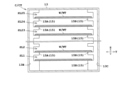
- Fig. 2 is a cross-sectional view of a carrier.
- Fig. 3 is a front view of the carrier.
- teaching positions TP1 to TP25 are called teaching positions TP.
- points EA1 to EA25 are called points EA.
- points EB1 to EB25 are not particularly distinguished, they are called points EB.
- distances DA1 to DA25 are not particularly distinguished, they are called distances DA.
- distances DB1 to DB25 are not particularly distinguished, they are called distances DB.
- standard center positions DP1 to DP25 are not particularly distinguished, they are called standard center positions DP.
- center positions CP1 to CP25 are not particularly distinguished, they are called center positions CP.
- positional deviation amounts DF1 to DF25 are not particularly distinguished, they are called positional deviation amounts DF.
- modified teaching positions RTP1 to RTP25 are not particularly distinguished, they are called modified teaching positions RTP.
- the substrate processing apparatus 1 processes a substrate W.
- the substrate processing apparatus 1 includes an indexer block 3 and a processing block 5.
- the indexer block 3 includes a plurality of (e.g., two) carrier placement units 7, a substrate transport robot IR, a wall unit 9, and a plurality of (e.g., two) lid attachment/detachment units 11.
- the horizontal direction in which the indexer block 3 and the processing block 5 are arranged is the X direction (front-rear direction).
- the horizontal direction in which the two carrier placement units 7 are arranged is the Y direction (width direction).
- the Y direction is perpendicular to the X direction.
- Each of the two carrier placement sections 7 places a carrier C on it.
- the carrier C stores multiple (e.g., 25) substrates W in a horizontal position arranged in the vertical direction (Z direction).
- the carrier C also stores multiple substrates W at a predetermined interval (e.g., 10 mm).
- the substrates W are formed in a disk shape.
- the substrates W may or may not be warped, and may be multiple substrates bonded together.
- a FOUP Front Opening Unify Pod
- the carrier may be what is called a cassette (open cassette) that does not have a lid 17 (described below) that covers the removal port 14 (described below).
- Carrier C includes a container 13, an outlet 14, a plurality of (e.g., 25) shelves 15, and a lid 17.
- Container 13 stores a plurality of substrates W.
- Outlet 14 is provided on the front of container 13.
- Outlet 14 is an opening for loading and unloading a plurality of substrates W.
- Substrates W in container 13 of carrier C are removed through outlet 14.
- Substrates W are stored through outlet 14.
- lid 17 that covers outlet 14 is attached to container 13.
- Outlet 14 corresponds to the carrier opening of the present invention.
- Carrier C corresponds to the processing carrier of the present invention.
- the multiple shelves 15 are arranged in the vertical direction (Z direction) inside the carrier C (container 13). In the vertical direction, the multiple shelves 15 are arranged at equal intervals (e.g., 10 mm intervals). Each of the multiple shelves 15 can support one substrate W in a horizontal position.
- the multiple shelf sections 15 include multiple (e.g., 25) shelves 15A and multiple (e.g., 25) shelves 15B.
- the 25 shelves 15A are provided on the left inner wall 13B of the container 13, and the 25 shelves 15B are provided on the right inner wall 13C of the container 13.
- the 25 shelves 15A each face the 25 shelves 15B.
- One substrate W is placed on each pair of shelves 15A, 15B.
- carrier C can accommodate a maximum of 25 substrates W (n is a natural number equal to or greater than 2). See FIG. 3.
- a space for accommodating one substrate W between two shelves 15 adjacent in the vertical direction (Z direction) is called a slot.
- Carrier C has 25 slots SL1, SL2 to SL23, SL24, and SL25.
- the 25 slots SL1 to SL25 are lined up in order from the bottom. Slot SL1 is the slot located at the lowest position, and slot SL25 is the slot located at the highest position.
- the two carrier mounting sections 7 are arranged at the front of the indexer block 3.
- the two carrier mounting sections 7 are arranged outside the front wall section 9A.
- the front wall section 9A has a passage opening 9C at a position corresponding to the removal opening 14 of the carrier C mounted on the carrier mounting section 7. That is, the front wall section 9A has two passage openings 9C (see Figure 1).
- the passage openings 9C are formed to be approximately the same size as the removal opening 14 of the carrier C.
- the substrate transport robot IR removes the substrate W from the carrier C mounted on the carrier mounting section 7 through the passage openings 9C.
- each passage opening 9C is blocked by a shutter portion 19 of the lid attachment/detachment portion 11 to separate the atmosphere outside and inside the wall portion 9.
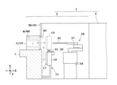
- Two lid attachment/detachment portions 11 are provided on each of the two carrier mounting portions 7. As shown in FIG. 5, each of the two lid attachment/detachment portions 11 includes a shutter portion 19, a shutter advance/retract portion 21, a shutter lift portion 23, and a height sensor 25.
- the shutter section 19 closes the passage opening 9C.
- the shutter section 19 also removes the lid section 17 from the carrier C and attaches the lid section 17 to the carrier C.
- the shutter section 19 also holds the removed lid section 17.
- the shutter advance/retract section 21 moves the shutter section 19 forward and backward in the X direction.
- the shutter lift section 23 moves the shutter section 19 up and down (Z direction).
- the shutter advance/retract section 21 and the shutter lift section 23 each include an electric motor.
- the height sensor 25 is composed of, for example, a linear encoder or a rotary encoder.
- the shutter advance/retract unit 21 advances and retreats the two distance sensors 31, 32 and the sensor movement unit 33 described below in the X direction.
- the shutter lift unit 23 raises and lowers the two distance sensors 31, 32 and the sensor movement unit 33 described below in the vertical direction (Z direction).
- the shutter lift unit 23 corresponds to the sensor lift unit of the present invention.
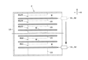
- the indexer block 3 further includes two distance sensors 31, 32 and a sensor moving unit 33.
- the two distance sensors 31, 32 are provided on the upper surface of the shutter unit 19 via the sensor moving unit 33. As shown in Figures 6 and 7, the two distance sensors 31, 32 are arranged to face the multiple substrates W in the carrier C via the removal port 14.
- the two distance sensors 31, 32 are arranged horizontally. In other words, the distance sensor 31 is arranged at the same height as the distance sensor 32.
- the two distance sensors 31, 32 each measure a distance.
- the two distance sensors 31, 32 measure two distances DA, DB between the two distance sensors 31, 32 and two different points (points EA, EB) on the periphery of the substrate W in the carrier C placed on the carrier placement section 7.
- the first distance sensor 31 measures the distance DA between the tip TA of the first distance sensor 31 and point EA on the periphery of the substrate W (see FIG. 8).
- the second distance sensor 32 measures the distance DB between the tip TB of the second distance sensor 32 and point EB on the periphery of the substrate W (see FIG. 8).
- Point EA is a different point from point EB. Note that points EA and EB are each positions that vary depending on, for example, the position where the laser light is irradiated. Also, it is assumed that the tips TA, TB are each in a reference position when measuring the distance.
- Each of the two distance sensors 31, 32 is an optical distance sensor.
- Each of the two distance sensors 31, 32 includes a light projector and a light receiver.
- the light projector irradiates a laser beam toward the object to be measured (e.g., the peripheral portion of the substrate W).
- the light receiver detects the laser beam reflected by the object to be measured.
- the first distance sensor 31 is configured in the same manner as the second distance sensor 32.
- each of the two distance sensors 31, 32 may irradiate light other than laser light, such as infrared light.
- each of the two distance sensors 31, 32 may be a sensor that uses ultrasonic waves.
- the sensor moving unit 33 is provided on the upper surface of the shutter unit 19. As shown in Figures 6 and 7, the sensor moving unit 33 moves the two distance sensors 31, 32 in the X direction between the measurement position MEP and the standby position.
- Figure 6 shows a state in which the two distance sensors 31, 32 are located at the standby position.
- Figure 7 shows a state in which the two distance sensors 31, 32 are located at the measurement position MEP. Note that the measurement position MEP and the standby position are preset positions.
- the sensor moving unit 33 includes a sensor support member 33A, two guide rails 33B, a screw shaft 33C, an electric motor 33D, and a position sensor (e.g., a rotary encoder) (not shown).
- the sensor support member 33A is formed in a C-shape in a plan view. Two distance sensors 31, 32 are attached to both ends of the C-shaped sensor support member 33A.
- the two guide rails 33B and the screw shaft 33C are arranged to extend in the X direction.
- the two guide rails 33B support the sensor support member 33A so that it can move in the X direction. In other words, the sensor support member 33A is guided in the X direction by the two guide rails 33B.
- the screw shaft 33C penetrates the sensor support member 33A and engages with the internal thread 33F of the sensor support member 33A.
- the output shaft of the electric motor 33D is connected to the base end of the screw shaft 33C.
- the position (coordinates) of point EA in the horizontal plane can be obtained from the position of tip TA of the first distance sensor 31, distance DA, and distance SF1.
- the position (coordinates) of point EB in the horizontal plane can be obtained from the position of tip TB of the second distance sensor 32, distance DB, and distance SF2.
- the center position of substrate W (standard substrate WT) is calculated from points EA, EB, and the diameter DM or radius of substrate W (standard substrate WT).
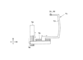
- FIG. 9 is a side view of the substrate transport robot IR.
- FIG. 10 is a plan view of the hand 35.
- the substrate transport robot IR has a hand 35 that supports one substrate W, and is capable of moving the hand 35.
- the substrate transport robot IR has an articulated arm 37 and a lifting platform 39.
- the hand 35 comprises a hand body 41 and three or more (e.g., four) guides 43.
- the hand body 41 is formed in a Y shape in a plan view.
- the four guides 43 are formed on the upper surface of the hand body 41.
- the four guides 43 receive the peripheral edge of the substrate W.
- Each of the four guides 43 comprises a receiving portion 43A and a guide wall 43B.
- the peripheral edge of the substrate W rests on the four receiving portions 43A.
- the four guide walls 43B surround the substrate W resting on the four receiving portions 43A and limit the movement of the substrate W in the horizontal direction (XY direction).
- the substrate W is misaligned on the horizontal plane and is not surrounded by the four guide walls 43B but placed on top of the guide walls 43B, a transport problem may occur, such as the substrate W falling off the hand 35.
- the articulated arm 37 is formed, for example, by a SCARA (selective compliance assembly robot arm) type robot arm.
- the base end (base end portion) of the articulated arm 37 is attached to a lifting platform 39.
- the tip end (tip end portion) of the articulated arm 37 is connected to the hand 35.
- the articulated arm 37 moves the hand 35 in the horizontal direction to transport the substrate.
- the articulated arm 37 is driven by multiple electric motors including the electric motor of the rotation drive unit 37D described below.
- the articulated arm 37 includes, for example, a first arm 37A, a second arm 37B, a third arm 37C, and a rotary drive unit 37D.
- the base end of the first arm 37A is attached to the rotary drive unit 37D so as to be rotatable around a vertical axis AX2.
- the base end of the second arm 37B is attached to the tip of the first arm 37A so as to be rotatable around a vertical axis AX3.
- the base end of the third arm 37C is attached to the tip of the second arm 37B so as to be rotatable around a vertical axis AX4.
- the tip of the third arm 37C is connected to the base end of the hand 35.
- the rotary drive unit 37D includes an electric motor.
- the rotary drive unit 37D rotates the first arm 37A around the vertical axis AX2.
- the rotation drive unit 37D is equipped with a rotary encoder 45A that measures the amount of rotation of the first arm 37A around the vertical axis AX2.
- the first arm 37A is equipped with a rotary encoder 45B that measures the amount of rotation of the second arm 37B around the vertical axis AX3.
- the second arm 37B is equipped with a rotary encoder 45C that measures the amount of rotation of the third arm 37C around the vertical axis AX4.
- the three rotary encoders 45A to 45C provide the position of the hand 35 in the XY direction. In other words, the position of the hand 35 in the horizontal plane is provided.
- the lifting platform 39 raises and lowers the hand 35 and the articulated arm 37.
- the lifting platform 39 includes a slider 39A, a guide rail 39B, a screw shaft 39C, an electric motor 39D, and a rotary encoder 39E.
- the slider 39A is fixed, for example, to the rotary drive unit 37D of the articulated arm 37.
- the guide rail 39B and the screw shaft 39C are each arranged to extend in the vertical direction (Z direction).
- the guide rail 39B and the screw shaft 39C each pass through the slider 39A.
- the screw shaft 39C meshes with the internal thread 39F of the slider 39A.
- the output shaft of the electric motor 39D is connected to the lower end of the screw shaft 39C.
- the rotary encoder 39E measures the height position of the hand 35 by measuring the amount of rotational movement of the output shaft and the screw shaft of the electric motor 39D.
- a linear encoder may be used instead of the rotary encoder 39E.
- the processing block 5 comprises a plurality of processing units 49, a center robot CR, and a substrate placement part (shelf) PS.
- the substrate placement part PS is provided between the substrate transport robot IR and the center robot CR.
- the substrate placement part PS can place one or more substrates W on it.
- each processing unit 49 performs a preset process on the substrate W.
- each processing unit 49 includes a holding and rotating part 51 and a nozzle 53.
- the holding and rotating part 51 includes a spin chuck that holds one substrate W in a horizontal position, and an electric motor that rotates the spin chuck around a vertical axis that passes through the center of the substrate W.
- the nozzle 53 ejects a processing liquid onto the top surface of the substrate W held by the holding and rotating part 51.
- the center robot CR has a hand 55 that supports one substrate W in a horizontal position.
- the center robot CR can move the hand 55.
- the center robot CR can transport the substrate W between multiple processing units 49 and the substrate placement part PS.
- the center robot CR is equipped with an advance/retract unit 57 and a lifting/rotating unit 59.
- the advance/retract unit 57 moves the hand 55 forward and backward.
- the lifting/rotating unit 59 rotates the hand 55 and the advance/retract unit 57 around the vertical axis AX5 to change the orientation of the hand 55.
- the lifting/rotating unit 59 also raises and lowers the hand 55 and the advance/retract unit 57 in the vertical direction (Z direction).
- the advance/retract unit 57 and the lifting/rotating unit 59 each have one or more electric motors.
- the advance/retract unit 57 also includes a position sensor (e.g., a rotary encoder or a linear encoder) that measures the position of the hand 55 when it is advanced or retreated.
- the lifting/rotating unit 59 includes a direction sensor (e.g., a rotary encoder) that detects the orientation of the hand 55 around the vertical axis AX5, and a height sensor (e.g., a rotary encoder or a linear encoder) that detects the height position of the hand 55.
- the position sensor and direction sensor provide the position of the hand 55 in the XY directions.
- FIG 11 is a block diagram showing the control system of the substrate processing apparatus 1.
- the substrate processing apparatus 1 includes a control unit 61 and a memory unit 63.
- the control unit 61 controls each component of the substrate processing apparatus 1 (e.g., the substrate transport robot IR, the two distance sensors 31, 32, and the lid attachment/detachment unit 11).
- the control unit 61 includes one or more processors, such as a central processing unit (CPU).
- the memory unit 63 includes at least one of a read-only memory (ROM), a random-access memory (RAM), and an auxiliary storage device (e.g., a hard disk).
- the memory unit 63 stores computer programs required to control each component of the substrate processing apparatus 1.
- the memory unit 63 also stores the diameter DM or radius of each of the substrate W and the standard substrate WT.
- the substrate processing apparatus 1 includes an alarm unit 65 and an input unit 67.
- the alarm unit 65 notifies the operator of information by emitting at least one of sound and light.
- the alarm unit 65 includes at least one of an electronic buzzer, a speaker, and an electric light.
- the input unit 67 includes at least one of a keyboard, a mouse, a joystick, a cross key, a button switch, and a touch panel.
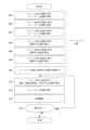
- Steps S01 to S07 are steps for a teaching process (teaching work).
- Steps S11 to S14 are steps for transporting a substrate W (product substrate) and processing the substrate W.
- the teaching process of the substrate transport robot IR will be described with reference to steps S01 to S07.
- the teaching process in this explanation is the task of having the substrate transport robot IR learn the positions to take when removing a substrate W from a carrier C placed on the carrier placement section 7, or when storing a substrate W in the carrier C.
- the standard carrier CT is placed on one of the two carrier placement sections 7 (one carrier placement section 7 and the other carrier placement section 7).
- the standard carrier CT is, for example, a carrier C that is free of distortion and formed almost exactly according to the design values.
- the standard carrier CT is a non-defective carrier C.
- the standard carrier CT and the standard substrate WT may also be made of metal (for example, aluminum).
- the standard carrier CT is configured to store 25 standard substrates WT, similar to the carrier C shown in Figures 2 and 3.
- the standard carrier CT placed on the carrier placement section 7 stores two standard substrates WT in the bottommost slot SL1 and the topmost slot SL25.
- the standard substrates WT are also substrates W that are free of distortion, for example, and formed approximately according to the design values.
- the two standard substrates WT are stored in preset positions within the two slots SL1 and SL25 of the standard carrier CT. Note that the standard carrier CT does not have a lid section 17 attached.
- the lid attachment/detachment section 11 retracts the shutter section 19, and then lowers the shutter section 19 to the position shown by the solid line in Figure 4. This opens the passage opening 9C in the front wall section 9A, allowing the substrate transport robot IR to access the inside of the standard carrier CT.
- Step S01 Acquisition of teaching position for substrate in slot SL1
- the operator causes the control unit 61 to control the substrate transport robot IR via the input unit 67.
- the substrate transport robot IR advances the hand 35 into the standard carrier CT so as to be positioned below the standard substrate WT stored in slot SL1.
- the substrate transport robot IR raises the hand 35 so that the upper surface of the hand 35 (the four receiving portions 43A of the four guides 43) is firmly in contact with the lower surface of the standard substrate WT in slot SL1 with the standard substrate WT almost placed on the shelf 15. This operation is visually confirmed by the operator, for example.
- the operator confirms contact with the standard substrate WT, he/she registers the position (coordinates in the XYZ directions) of the hand 35. That is, the operator causes the control unit 61 to obtain position data from the four rotary encoders 39E, 45A-45C through the input unit 67 and set it as the teaching position TP1. For example, when the hand 35 is at the teaching position TP1, the position of the symbol FP shown in Figures 9 and 10 is at the teaching position TP1. The control unit 61 causes the teaching position TP1 to be stored in the memory unit 63.
- Step S02 Obtaining the teaching position for the substrate in slot SL25
- the operator then causes the control unit 61 to control the substrate transport robot IR via the input unit 67.
- the substrate transport robot IR advances the hand 35 into the standard carrier CT so that it is positioned below the standard substrate WT stored in slot SL25.
- the substrate transport robot IR then raises the hand 35 to pick up the standard substrate WT, thereby bringing the upper surface of the hand 35 into firm contact with the lower surface of the standard substrate WT in slot SL25, with the standard substrate WT almost resting on the shelf unit 15.
- the operator confirms contact with the standard substrate WT, he or she registers the position of the hand 35 (coordinates in the XYZ directions). That is, the operator causes the control unit 61 to obtain the position from the four rotary encoders 39E, 45A-45C through the input unit 67 and set it as the teaching position TP25. For example, when the hand 35 is at the teaching position TP25, the position of the symbol FP shown in Figures 9 and 10 is at the teaching position TP25. The control unit 61 causes the teaching position TP25 to be stored in the memory unit 63.
- control unit 61 calculates 23 (n-2) teaching positions TP2 to TP24 between the two teaching positions TP1 and TP25 based on the geometric relationship between the two teaching positions TP1 and TP25.
- the control unit 61 calculates 23 teaching positions TP2 to TP24 (coordinates in the XYZ directions) so that the 25 teaching positions TP1 to TP25 are arranged at equal intervals on a straight line LN1 that connects the two teaching positions TP1 and TP25. During this calculation, the two teaching positions TP1 and TP25 do not change.
- the 25 teaching positions TP1 to TP25 are stored in the memory unit 63.
- control unit 61 calculates the Z components of the 23 teaching positions TP2 to TP24 so that the Z components of the 25 teaching positions TP1 to TP25 are arranged at equal intervals on the Z component of the straight line LN1 that connects the two teaching positions TP1 and TP25, as shown in Figure 15.
- the control unit 61 also calculates the X components of the 23 teaching positions TP2 to TP24 so that the X components of the 25 teaching positions TP1 to TP25 are equally spaced on the X component of the straight line LN1 that connects the two teaching positions TP1 and TP25, as shown in Figure 16. Furthermore, the control unit 61 calculates the Y components of the 23 teaching positions TP2 to TP24 so that the Y components of the 25 teaching positions TP1 to TP25 are equally spaced on the Y component of the straight line LN1 that connects the two teaching positions TP1 and TP25.
- Step S04 Calculation of standard center position of substrate in slot SL1
- the operator moves the hand 35 via the input unit 67 to a position that does not interfere with the operation of the lid attaching/detaching unit 11 and the sensor moving unit 33.
- the standard carrier CT remains placed on one of the carrier placement units 7.
- the operator causes the control unit 61 to control the lid attachment/detachment unit 11, the sensor movement unit 33, and the two distance sensors 31, 32 via the input unit 67.
- the shutter lifting unit 23 of the lid attachment/detachment unit 11 raises the two distance sensors 31, 32 to a height position facing the standard substrate WT in the slot SL1 in the standard carrier CT.
- the sensor movement unit 33 advances the two distance sensors 31, 32 from the standby position to the measurement position MEP shown in Figure 7. This makes the two distance sensors 31, 32 ready for measurement.
- the two distance sensors 31, 32 each irradiate the laser light onto the peripheral portion of the standard substrate WT in the slot SL1, as shown by the dashed lines in Figure 17.
- the first distance sensor 31 measures the distance DA1 to the point EA1 on the peripheral portion of the standard substrate WT, as shown in Figure 8.
- the second distance sensor 32 measures the distance DB1 to the point EB1 on the peripheral portion of the standard substrate WT.
- the two measured distances DA1, DB1 are stored in the memory unit 63.
- the control unit 61 also calculates the center position (X-coordinate and Y-coordinate) of the horizontal plane (XY direction) of the standard substrate WT in the slot SL1 based on the two distances DA1, DB1 and the diameter DM or radius of the standard substrate WT.
- the calculated center position is stored in the memory unit 63 as the XY coordinates of the standard center position DP1.
- the height sensor 25 of the lid attachment/detachment unit 11 measures the height positions of the two distance sensors 31, 32 from which the distances DA1, DB1 were measured, i.e., the height positions of the points EA1, EB1.
- the height positions of the points EA1, EB1, or their average height position, are stored in the memory unit 63 as the Z-coordinates of the standard center position DP1.
- Step S05 Calculation of standard center position of substrate in slot SL25
- the shutter lifting unit 23 raises the two distance sensors 31, 32 to a height position facing the standard substrate WT in the slot SL25 in the standard carrier CT.
- the two distance sensors 31, 32 remain in the state where they are moved to the measurement position MEP.
- the two distance sensors 31, 32 each irradiate the peripheral portion of the standard substrate WT in the slot SL25 with laser light, as shown by the solid lines in FIG. 17.
- the first distance sensor 31 measures the distance DA25 to the point EA25 on the peripheral portion of the standard substrate WT.
- the second distance sensor 32 measures the distance DB25 to the point EB25 on the peripheral portion of the standard substrate WT.
- the two measured distances DA25, DB25 are stored in the memory unit 63.
- the control unit 61 also calculates the center position (X-coordinate and Y-coordinate) of the horizontal plane (XY direction) of the standard substrate WT in the slot SL25 based on the two distances DA25, DB25 and the diameter DM or radius of the standard substrate WT.
- the calculated center position is stored in the memory unit 63 as the XY coordinates of the standard center position DP25.
- the height sensor 25 of the lid attachment/detachment unit 11 measures the height positions of the two distance sensors 31, 32 at which the distances DA25, DB25 are measured, i.e., the height positions of the points EA25, EB25.
- the height positions of the points EA25, EB25, or their average height position, are stored in the memory unit 63 as the Z-coordinates of the standard center position DP25.
- Step S06 Calculation of Standard Center Positions for Slots SL2 to SL24
- the control unit 61 calculates the 23 standard center positions DP2 to DP24 for the slots SL2 to SL24 in the same manner as in step S03.
- the control unit 61 calculates 23 standard center positions DP2 to DP24 between the two standard center positions DP1 and DP25 based on the geometric relationship between the two standard center positions DP1 and DP25.
- the control unit 61 calculates 23 standard center positions DP2 to DP24 so that the 25 standard center positions DP1 to DP25 are arranged at equal intervals on a straight line LN2 that connects the standard center positions DP1 and DP25. During this calculation, the two standard center positions DP1 and DP25 do not change.
- the standard center positions DP1 to DP25 (coordinates in the X, Y, and Z directions) are stored in the memory unit 63.
- Step S07 Associating Teaching Positions with Standard Center Positions Thereafter, the control unit 61 associates the 25 standard center positions DP1 to DP25 with the 25 teaching positions TP1 to TP25, respectively.
- the standard center position DP1 is associated with the teaching position TP1.
- the standard center position DP2 is associated with the teaching position TP2.
- the standard center position DP3 is associated with the teaching position TP3.
- the standard center position DP25 is associated with the teaching position TP25. Note that the timing of the association is not limited to the timing after step S06.
- the sensor movement unit 33 of the lid attachment/detachment unit 11 retracts the two distance sensors 31, 32 to their standby positions (see FIG. 6). After that, the shutter advance/retract unit 21 and the shutter lift unit 23 close the passage opening 9C with the shutter unit 19.
- the standard carrier CT storing the two standard substrates WT is moved from one carrier placement section 7 to the other carrier placement section 7.
- steps S01 to S07 a teaching process is performed for the substrate transport robot IR associated with the other carrier placement section 7.
- a teaching process is performed for the substrate transport robot IR for each carrier placement section 7.
- a carrier C storing 25 substrates W is placed on one of the two carrier mounting sections 7.
- the lid attachment/detachment section 11 removes the lid section 17 from the carrier C placed on the carrier mounting section 7 and holds the removed lid section 17.
- the shutter advance/retract section 21 of the lid attachment/detachment section 11 retracts the lid section 17 towards the substrate transport robot IR. This opens the passage opening 9C.
- the shutter lift section 23 of the lid attachment/detachment section 11 slightly lowers the shutter section 19 to move (advance) the two distance sensors 31, 32 into the carrier C.
- Step S11 Calculation of central positions of substrates (product substrates) in slots SL1 to SL25
- the sensor moving unit 33 moves (advances) the two distance sensors 31, 32 from the standby position to the measurement position MEP (see FIG. 7).
- the shutter lifting unit 23 lowers the two distance sensors 31, 32 to detect the presence or absence of a substrate W and to measure the two distances DA, DB (see FIG. 20). Note that the direction in which the two distance sensors 31, 32 are moved may be upward.
- the two distance sensors 31, 32 While the two distance sensors 31, 32 are descending, the two distance sensors 31, 32 measure two distances DA (DA1-DA25), DB (DB1-DB25) between the two distance sensors 31, 32 and two different points EA (EA1-EA25), EB (EB1-EB25) on the periphery of each substrate W stored in a carrier C placed on the carrier placement section 7.
- DA DA1-DA25
- DB DB1-DB25
- EA EA1-EA25
- EB EB1-EB25
- the two distance sensors 31, 32 measure two distances DA25, DB25 to two different points EA25, EB25 on the periphery of the substrate W stored in slot SL25.
- the two distance sensors 31, 32 also measure two distances DA24, DB24 to two different points EA24, EB24 on the periphery of the substrate W stored in slot SL24.
- the two distance sensors 31, 32 also measure two distances DA1, DB1 to two different points EA1, EB1 on the periphery of the substrate W stored in slot SL1.
- the control unit 61 also calculates the center position CP (CP1 to CP25) of each substrate in the horizontal plane (XY direction) based on the two distances DA, DB corresponding to each substrate W and the diameter DM or radius of each substrate W.
- the center position CP25 in the horizontal plane of the substrate W stored in slot SL25 is calculated based on the two distances DA25, DB25 corresponding to the substrate W stored in slot SL25 and the diameter DM (e.g., 300 mm) or radius (e.g., 150 mm) of the substrate W.
- the diameter DM e.g. 300 mm
- radius e.g. 150 mm
- a central position CP24 in the horizontal plane of the substrate W stored in slot SL24 is calculated based on the two distances DA24, DB24 corresponding to the substrate W stored in slot SL24 and the diameter DM or radius of the substrate W.
- a central position CP1 in the horizontal plane of the substrate W stored in slot SL1 is calculated based on the two distances DA1, DB1 corresponding to the substrate W stored in slot SL1 and the diameter DM or radius of the substrate W.
- the height sensor 25 of the lid attachment/detachment part 11 also measures the height positions of the two distance sensors 31, 32 at which 25 pairs of distances DA, DB (DA1 to DA25, DB1 to DB25) are measured, i.e., the height positions of points EA, EB.
- the height positions of points EA, EB, or their average height position are stored in the memory unit 63 as the Z-direction coordinate of the center position CP. That is, 25 height positions (Z-direction coordinates) corresponding to the 25 substrates W are stored in the memory unit 63.
- the two distance sensors 31, 32 also detect the presence or absence of a substrate W in the carrier C. For example, if the two distance sensors 31, 32 output two distances DA25, DB25 for slot SL25, the control unit 61 determines that a substrate W is present in slot SL25. In contrast, if the two distance sensors 31, 32 do not output two distances DA25, DB25 for slot SL25, the control unit 61 determines that a substrate W is not present in slot SL25. Even if distances DA25, DB25 are output, if they are not within a preset range, the control unit 61 determines that a substrate W is not present in slot SL25.
- the 25 center positions CP1 to CP25 (coordinates in the XYZ directions) including the 25 height positions are stored in the memory unit 63.
- the 25 distances DA1 to DA25 and the 25 distances DB1 to DB25 are also stored in the memory unit 63.
- Information on the presence or absence of the 25 slots SL1 to SL25 is also stored in the memory unit 63.
- Step S12 Correcting the teaching positions With reference to Fig. 21, the control unit 61 calculates 25 positional deviation amounts DF1 to DF25 (positional deviation amounts in the X, Y and Z directions) of the 25 center positions CP1 to CP25 based on the 25 standard center positions DP1 to DP25.
- the 25 slots SL1 to SL25 (25 standard slots) of the standard carrier CT correspond to the 25 slots SL1 to SL25 of the carrier C. Therefore, for example, slot SL25 of the standard carrier CT corresponds to slot SL25 of the carrier C.
- the positional deviation amount DF25 of the center position CP25 corresponding to the substrate W stored in the slot SL25 of the carrier C is calculated based on the standard center position DP25 related to the slot SL25 of the standard carrier CT.
- slot SL24 of the standard carrier CT corresponds to slot SL24 of carrier C.
- slot SL1 of standard carrier CT corresponds to slot SL1 of carrier C.
- the control unit 61 When any of the 25 positional deviation amounts DF1 to DF25 exceeds a preset range, the control unit 61 notifies the operator by the notification unit 65 that the range has been exceeded.
- the positional deviation amount DF exceeds the preset range, it may not be possible to place the substrate W inside the four guide walls 43B of the four guides 43 shown in FIG. 10. In this case, a transport problem may occur during transport of the substrate W, such as the substrate W falling from the hand 35.
- the notification from the notification unit 65 makes it possible to avoid transport problems that may occur even if the teaching position TP is corrected.
- Step S13 Substrate Transport Thereafter, the substrate transport robot IR uses the hand 35 to take out the 25 substrates W one by one from the carrier C placed on the carrier platform 7, based on the 25 corrected teaching positions RTP1 to RTP25. The substrate transport robot IR transports the taken-out substrates W to the substrate platform PS.
- the center robot CR picks up the substrate W from the substrate placement part PS and transports the substrate W to one of the multiple processing units 49.
- Each processing unit 49 performs a preset process (e.g., a cleaning process using pure water) on the substrate W transported by the center robot CR.
- the center robot CR takes a processed substrate W that has been subjected to a preset process from one of the multiple processing units 61, and transports the substrate W to the substrate placement part PS.
- the substrate transport robot IR takes the processed substrate W from the substrate placement part PS, and returns the substrate W to the carrier C on the carrier placement part 7.
- the substrate transport robot IR uses the hand 35 to return the 25 substrates W one by one to the carrier C based on the 25 corrective teaching positions RTP1 to RTP25.
- Step S14 Repeat? The process returns to step S11 when a substrate W (product substrate) stored in another carrier C is to be processed by the processing unit 49. When the teaching process is to be performed again, the process ends and returns to step S01.
- two distance sensors 31, 32 are arranged horizontally so as to face the substrates W in the carrier C through the removal port 14. While the two distance sensors 31, 32 are moving, the control unit 61 measures two distances DA, DB to two different points EA, EB on the periphery of each substrate W in the carrier C placed on the carrier placement unit 7 using the two distance sensors 31, 32. The control unit 61 also calculates the center position CT of each substrate W in the horizontal plane from the two distances DA, DB and the diameter DM or radius of each substrate W. The calculated center position CT in the horizontal plane indicates the exact position of the substrate W. Therefore, even if the substrate W is misaligned in the horizontal plane, problems with the substrate W being transported by the substrate transport robot IR can be prevented.
- the position for the hand 35 to pick up the standard substrate WT stored in the slot SL1 of the standard carrier CT is set as the teaching position TP1.
- two distances DA1, DB1 to the standard substrate WT are measured by the two distance sensors 31, 32, respectively.
- the standard center position DP1 is then calculated based on the two distances DA1, DB1 and the diameter DM or radius of the standard substrate WT.
- the standard center position DP1 is associated with the teaching position TP1.
- the positional deviation amount DF1 of the center position CT1 of the substrate W stored in the slot SL1 of the carrier C corresponding to the slot SL1 of the standard carrier CT is calculated based on the standard center position DP1.
- the teaching position TP1 is corrected using the calculated positional deviation amount DF1. Therefore, the teaching position TP1 in the horizontal plane can be corrected well.
- the teaching process is performed for the bottom slot SL1 and the top slot SL25 of the standard carrier CT, and a calculation is performed from a geometric relationship for at least one slot between them, SL2 to SL24. This makes it easy to perform the teaching process.
- slot SL1 of the standard carrier CT corresponds to the first standard slot of the present invention.
- Slot SL25 of the standard carrier CT corresponds to the second standard slot of the present invention.
- At least one of the 23 slots SL2 to SL24 of the standard carrier CT corresponds to the third standard slot of the present invention.
- teaching position TP1 corresponds to the first teaching position of the present invention.
- Teaching position TP25 corresponds to the second teaching position of the present invention.
- At least one of the 23 teaching positions TP2 to TP24 corresponds to the third teaching position of the present invention.
- the standard center position DP1 corresponds to the first standard center position of the present invention.
- the standard center position DP25 corresponds to the second standard center position of the present invention.
- At least one of the 23 standard center positions DP2 to DP24 corresponds to the third standard center position of the present invention.
- the diameter DM or radius corresponds to the diameter of the present invention.
- the two distance sensors 31, 32 are provided on the upper surface of the shutter unit 19 via the sensor moving unit 33.
- the two distance sensors 31, 32 may be provided separately from the lid attaching/detaching unit 11 and the substrate transport robot IR.
- the indexer block 3 includes a sensor unit 71.
- the sensor unit 71 includes two distance sensors 31, 32, a sensor support member 73, a forward/backward movement unit 75, a lifting/lowering unit 76, and a height sensor 78.
- the sensor support member 73 supports the two distance sensors 31, 32 that are aligned in the Y direction.
- the advance/retract unit 75 advances and retreats the two distance sensors 31, 32 and the sensor support member 73 in the X direction.
- the lifting unit 76 moves the two distance sensors 31, 32, the sensor support member 73, and the advance/retract unit 75 up and down (Z direction).
- the advance/retract unit 75 and the lifting unit 76 each include an electric motor.
- the height sensor 78 is composed of, for example, a linear encoder or a rotary encoder.
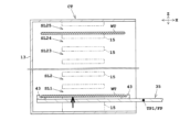
- the sensor unit 71 moves the two distance sensors 31, 32 etc. so as not to interfere with the lid attachment/detachment unit 11. As shown by the dashed line in Figure 22, the sensor unit 71 keeps the two distance sensors 31, 32 waiting in a position that does not interfere with the substrate transport by the substrate transport robot IR. Also, as shown by the solid line in Figure 22, when measuring distance, the sensor unit 71 moves the two distance sensors 31, 32 to a measurement position MEP (see Figures 7 and 8) within the carrier C placed on the carrier placement unit 7.
- the indexer block 3 is equipped with a sensor unit 71 and the lid attachment/detachment unit 11 is not necessary, the indexer block 3 does not need to be equipped with the lid attachment/detachment unit 11.
- the substrate transport robot IR is equipped with one hand 35.
- the substrate transport robot IR may be equipped with two or more hands 35.
- the substrate transport robot IR has, for example, five hands 35 and a hand connecting member 81. Each of the five hands 35 supports one substrate W. The five hands 35 are arranged in the vertical direction at intervals of, for example, 10 mm, like the intervals between the shelves 15 of the carrier C. The hand connecting member 81 connects to the five hands 35. Therefore, the substrate transport robot IR can move the hands 35 as a unit.
- the teaching position TP may be obtained and corrected as follows. For example, it is assumed that a standard substrate WT is stored in slot SL3 (third row from the bottom) of the standard carrier CT placed on the carrier placement section 7. Furthermore, the hand 35 in the third row from the bottom of the five hands 35 is indicated by the reference symbol 35A.
- step S01 first, the substrate transport robot IR advances the five hands 35 into the standard carrier CT so that the hands 35A are positioned below the standard substrate WT.
- the substrate transport robot IR then raises the five hands 35 so that the upper surfaces of the hands 35A come into contact with the lower surface of the standard substrate WT in the slot SL3.
- the control unit 61 acquires position data from the four rotary encoders 39E, 45A-45C for the position where the hands 35A come into contact, and sets this as the teaching position TP3. For example, when the five hands 35 are at the teaching position TP3, the position of the symbol FP shown in FIG. 24 is deemed to be at the teaching position TP3.
- step S04 the shutter lifting unit 23 moves the two distance sensors 31, 32 to a height position corresponding to the standard substrate WT stored in slot SL3 of the standard carrier CT.
- the control unit 61 then obtains the two distances DA3, DB3 relating to the standard substrate WT using the two distance sensors 31, 32.
- the control unit 61 then calculates the standard center position DP3 in the horizontal plane of the standard substrate WT based on the two distances DA3, DB3, etc.
- step S07 the standard center position DP3 is associated with the teaching position TP1.
- step S11 the control unit 61 calculates the center positions CP1 to CP25 for the 25 substrates W in the carrier C. In addition, when five hands 35 support five substrates W, the control unit 61 calculates the average value of the five center positions CP1 to CP5 in the horizontal plane corresponding to the five substrates.
- step S12 the control unit 61 calculates the average positional deviation amount DF3 of the center positions CP1 to CP5 corresponding to the five substrates W based on the standard center position DP3.
- the control unit 61 uses the average positional deviation amount DF3 to correct the teaching position TP3 associated with the standard center position DP3.
- the control unit 61 transports five substrates W from carrier C to slots SL1 to SL5 using the substrate transport robot IR based on the corrected teaching position TP3 (i.e., corrected teaching position RTP3). That is, the control unit 61 transports five substrates W from carrier C using the substrate transport robot IR based on the average value of the five center positions CP1 to CP5.
- the average value of the five center positions CT corresponding to the five substrates W supported by the five hands 35 is calculated, and the five substrates W are transported based on this average value. Therefore, even if the substrates W are misaligned in the horizontal plane, problems with substrate transport by the substrate transport robot can be prevented.
- the two distance sensors 31, 32 are provided on the upper surface of the shutter section 19 via the sensor moving section 33.
- the two distance sensors 31, 32 may be provided at the tip of the hand 35 of the substrate transport robot IR.
- the substrate transport robot IR may be provided with another multi-joint arm 37, and the two distance sensors 31, 32 may be provided at the tip of the multi-joint arm 37.
- the two distance sensors 31, 32 are provided on the upper surface of the shutter section 19 via the sensor moving section 33.
- the two distance sensors 31, 32 may be provided on the upper surface of the shutter section 19 without via the sensor moving section 33.
- the two distance sensors 31, 32 measure the two distances DA, DB while being fixed to the upper surface of the shutter section 19 without being moved in the X direction.
- the sensor moving unit 33 moves the two distance sensors 31, 32 forward and backward in the X direction.
- the sensor moving unit 83 may swing each of the two distance sensors 31, 32.
- the sensor moving unit 83 includes a swinging member 85 to which the distance sensor 31 is attached, a swinging member 87 to which the distance sensor 32 is attached, and at least one electric motor (not shown).
- the sensor moving unit 83 swings the distance sensor 31 around the vertical axis AX7, and swings the distance sensor 32 around the vertical axis AX8.
- the 23 teaching positions TP2 to TP24 were obtained based on the two teaching positions TP1 and TP25.
- the 23 teaching positions TP2 to TP24 may be obtained using a standard substrate WT stored in a standard carrier CT, as in steps S01 and S02 shown in FIG. 12.
- the 23 standard center positions DP2 to DP24 are obtained based on the two standard center positions DP1 and DP25.
- the 23 standard center positions DP2 to DP24 may be obtained using a standard substrate WT stored in a standard carrier CT, as in steps S04 and S05 shown in FIG. 12. This allows the teaching positions in the horizontal plane to be properly corrected for all 25 substrates W in carrier C.
- the indexer block 3 is provided with two distance sensors 31, 32.
- the indexer block 3 may be provided with three or more distance sensors.
- the indexer block 3 may be provided with at least two distance sensors.
- the center position CP can be calculated with even higher accuracy based on the three distances and the diameter DM or radius.
- the substrate transport robot IR is provided with an articulated arm 37 and a lifting platform 39.
- the substrate transport robot IR may be provided with an advance/retract unit 57 and a lifting/rotating unit 59, like the center robot CR.
- REFERENCE SIGNS LIST 1 ... substrate processing apparatus 7 ... carrier placement section IR ; substrate transport robot 11 ... lid attachment/detachment section 14 ... removal opening SL1 to SL25 ... slot 23 ... shutter lift section 25 ... height sensor 31, 32 ... distance sensor 35 ... hand 39E, 45A to 45C ... rotary encoder 61 ... control section 63 ... memory section 65 ... notification section TP (TP1 to TP25) ... teaching position EA (EA1 to EA25) ... point EB (EB1 to EB25) ... point DA (DA1 to DA25) ... distance DB (DB1 to DB25) ... distance DP (DP1 to DP25) ...
Landscapes
- Engineering & Computer Science (AREA)
- Human Computer Interaction (AREA)
- Robotics (AREA)
- Mechanical Engineering (AREA)
- Container, Conveyance, Adherence, Positioning, Of Wafer (AREA)
- Manipulator (AREA)
Abstract
本発明は、基板処理装置および基板搬送方法に関する。制御部は、シャッタ昇降部により2個の距離センサ31,32を上下方向に移動させ、2個の距離センサ31,32の移動中に、2個の距離センサ31,32により、2個の距離センサ31,32と、キャリア載置部に載置されたキャリアに収納された各基板Wの周縁部の異なる2点EA,EBとの間の2つの距離DA,DBをそれぞれ計測し、各基板Wに対応する2つの距離DA,DBと各基板Wの直径DMまたは半径に基づいて、各基板Wの水平面における中心位置CPを算出し、各基板Wの水平面における中心位置CPに基づいて、基板搬送ロボットによりキャリアから複数枚の基板Wを搬送する。
Description
本発明は、基板を処理する基板処理装置および基板搬送方法に関する。基板は、例えば、半導体基板、FPD(Flat Panel Display)用の基板、フォトマスク用ガラス基板、光ディスク用基板、磁気ディスク用基板、セラミック基板、太陽電池用基板などが挙げられる。FPDは、例えば、液晶表示装置、有機EL(electroluminescence)表示装置などが挙げられる。
従来の基板処理装置は、キャリアに対して基板を出し入れする方向の異なる2つの位置に配置された2組のマッピングセンサ(透過型のセンサ)を備える。2組のマッピングセンサをキャリア内に進入させた後に、2組のマッピングセンサを下側に移動させる。これにより、異なる2つの位置における基板の2つの高さが検出される。この基板の2つの高さに基づいて、傾いた基板の差分高さと、キャリアの奥側への基板位置ずれ量が検出される(例えば、特許文献1参照)。
特許文献2には、収納部(キャリア)に収納された各基板の位置、形状等を検出するための機構である検出部を備えた基板搬送装置が開示されている。検出部は、赤外線、超音波等を利用した3つの距離センサを備える。
しかし、従来の基板処理装置は、次の問題がある。基板搬送ロボットは、キャリア載置部に載置されたキャリアから基板を取り出す。この際、例えば、キャリアの形状等の誤差があると、基板搬送ロボットのハンドが予め登録された位置にしか移動しないので、基板の取り損ねなどの搬送トラブルが起こる場合がある。
特許文献1では、キャリアの奥側への基板位置ずれ量が検出される。しかし、キャリアに対して基板を出し入れする方向と直交する水平方向の基板の位置ずれ量を検出することができない。
本発明は、このような事情に鑑みてなされたものであって、水平面において基板が位置ずれしていても基板の搬送トラブルを防止することができる基板処理装置および基板搬送方法を提供することを目的とする。
本発明は、このような目的を達成するために、次のような構成をとる。すなわち、本発明に係る基板処理装置は、上下方向に配置された水平姿勢の複数枚の基板を収納する複数個のスロット、および前記複数枚の基板を出し入れするためのキャリア開口を有する処理用キャリアを載置するキャリア載置部と、1枚の基板を支持するハンドを有し、前記ハンドを移動させることができる基板搬送ロボットと、前記キャリア開口を介して前記処理用キャリア内の前記複数枚の基板に対向するように、水平に配置された2個の距離センサと、前記2個の距離センサを上下方向に移動させるセンサ昇降部と、制御部と、を備え、前記制御部は、前記センサ昇降部により前記2個の距離センサを上下方向に移動させ、前記2個の距離センサの移動中に、前記2個の距離センサにより、前記2個の距離センサと、前記キャリア載置部に載置された前記処理用キャリアに収納された各基板の周縁部の異なる2点との間の2つの距離をそれぞれ計測し、各基板に対応する前記2つの距離と各基板の径に基づいて、各基板の水平面における中心位置を算出し、各基板の水平面における前記中心位置に基づいて、前記基板搬送ロボットにより前記処理用キャリアから前記複数枚の基板を搬送することを特徴とするものである。
本発明に係る基板処理装置によれば、キャリア開口を介して処理用キャリア内の複数枚の基板に対向するように水平に配置された2個の距離センサを備える。制御部は、2個の距離センサの移動中に、2個の距離センサによりキャリア載置部に載置された処理用キャリア内の各基板の周縁部の異なる2点までの2つの距離を計測する。また、制御部は、各基板における2つの距離と各基板の径から各基板の水平面の中心位置を算出する。算出された水平面における中心位置は、基板の正確な位置を示す。そのため、水平面において基板が位置ずれしていても、基板搬送ロボットによる基板の搬送トラブルを防止することができる。
また、上述の基板処理装置において、前記制御部は、ティーチング処理とティーチング修正処理とを実行し、前記ティーチング処理として、前記基板搬送ロボットにより、前記キャリア載置部に載置された標準キャリアに前記ハンドを進入させ、前記標準キャリアの複数個の標準スロットのうちの所定の標準スロットに収納された標準基板を前記ハンドで取るための位置を、ティーチング位置として設定し、前記センサ昇降部により前記標準スロットに収納された前記標準基板に対応する高さ位置に前記2個の距離センサを上下方向に移動させ、前記2個の距離センサにより、前記2個の距離センサと、前記標準スロットに収納された前記標準基板の周縁部の異なる2点との間の2つの標準距離をそれぞれ計測し、前記2つの標準距離と前記標準基板の径に基づいて、前記標準基板の水平面における標準中心位置を算出し、前記標準中心位置を前記ティーチング位置に関連付けること、を実行し、次に、前記処理用キャリアからの基板搬送のときに、前記ティーチング修正処理として、前記センサ昇降部により前記2個の距離センサを上下方向に移動させ、前記2個の距離センサの移動中に、前記2個の距離センサにより、前記2個の距離センサと、前記キャリア載置部に載置された前記処理用キャリアに収納された各基板の周縁部の異なる2点との間の2つの距離をそれぞれ計測し、各基板に対応する前記2つの距離と各基板の径に基づいて、各基板の水平面における中心位置を算出し、前記処理用キャリアの前記複数個のスロットのうち、前記標準スロットに対応するスロットに収納された基板に係る前記中心位置の位置ずれ量を、前記標準中心位置を基準に算出し、前記位置ずれ量を用いて、前記標準中心位置に関連付けられた前記ティーチング位置を修正すること、を行い、修正された前記ティーチング位置に基づいて、前記基板搬送ロボットにより前記処理用キャリアから前記複数枚の基板のうちの前記基板を搬送することが好ましい。
標準キャリアの所定の標準スロットに収納された標準基板をハンドで取るための位置は、ティーチング位置として設定される。また、2個の距離センサにより、その標準基板までの2つの標準距離がそれぞれ計測される。そして、標準中心位置は、2つの標準距離と標準基板の径に基づいて算出される。標準中心位置は、ティーチング位置に関連付けられる。標準スロットに対応する処理用キャリアのスロットに収納された基板に係る中心位置の位置ずれ量を、標準中心位置を基準に算出する。ティーチング位置は、算出された位置ずれ量を用いて修正される。そのため、水平面におけるティーチング位置を良好に修正できる。
また、上述の基板処理装置において、前記制御部は、前記標準キャリアの前記複数個の標準スロットの全てについて前記ティーチング処理を行い、前記処理用キャリアの前記複数個のスロットの全てについて前記ティーチング修正処理を行うことが好ましい。これにより、処理用キャリアの複数枚の基板の全てについて、水平面におけるティーチング位置を良好に修正できる。
また、上述の基板処理装置において、前記制御部は、前記標準キャリアの前記複数個の標準スロットのうちの最下段の第1標準スロットと最上段の第2標準スロットについて前記ティーチング処理を実行し、前記複数個の標準スロットのうちの前記第1標準スロットと前記第2標準スロットの間の第3標準スロットに係る前記ティーチング処理として、前記第1標準スロットに係る第1ティーチング位置と、前記第2標準スロットに係る第2ティーチング位置との幾何学的関係から、前記第3標準スロットに係る第3ティーチング位置を算出し、前記第1標準スロットに係る第1標準中心位置と、前記第2標準スロットに係る第2標準中心位置との幾何学的関係から、前記第3標準スロットに係る第3標準中心位置を算出し、前記第3標準中心位置を前記第3ティーチング位置に関連付け、前記処理用キャリアの前記複数個のスロットの全てについて前記ティーチング修正処理を行うことが好ましい。
標準キャリアの最下段の第1標準スロットと最上段の第2標準スロットについてティーチング処理が実行され、それらの間の第3標準スロットについては幾何学的関係からの算出が行われる。そのため、ティーチング処理を容易に行うことができる。
また、上述の基板処理装置において、前記基板搬送ロボットは、前記ハンドを含む2以上のハンドであって、1枚の基板を各々支持する前記2以上のハンドを有し、前記2以上のハンドを一体的に移動させることができ、前記制御部は、前記2以上のハンドが前記複数枚の基板のうちの2枚以上の基板を支持する場合、前記2枚以上の基板に対応する水平面における2以上の前記中心位置の平均値を算出し、前記平均値に基づいて、前記基板搬送ロボットにより前記処理用キャリアから前記2枚以上の基板を搬送することが好ましい。
2以上のハンドが一体的に移動される場合、2以上のハンドが支持する2枚以上の基板に対応する2以上の中心位置の平均値が算出され、その平均値に基づいて2枚以上の基板が搬送される。そのため、水平面において基板が位置ずれしていても、基板搬送ロボットによる基板の搬送トラブルを防止することができる。
また、上述の基板処理装置において、音および光の少なくとも一方を発する報知部を更に備え、前記制御部は、前記位置ずれ量が予め設定された範囲を超えるときは、前記報知部により音および光の少なくとも一方を発することが好ましい。これにより、操作者は、位置ずれ量が予め設定された範囲を超えたことを認識することができる。
また、本発明に係る基板搬送方法は、上下方向に配置された水平姿勢の複数枚の基板を収納する複数個のスロット、および前記複数枚の基板を出し入れするためのキャリア開口を有する処理用キャリアを載置するキャリア載置部と、1枚の基板を支持するハンドを有し、前記ハンドを移動させることができる基板搬送ロボットと、前記キャリア開口を介して前記処理用キャリア内の前記複数枚の基板に対向するように、水平に配置された2個の距離センサと、前記2個の距離センサを上下方向に移動させるセンサ昇降部と、を備えた基板処理装置の基板搬送方法であって、前記センサ昇降部により前記2個の距離センサを上下方向に移動させるセンサ移動工程と、前記2個の距離センサの移動中に、前記2個の距離センサにより、前記2個の距離センサと、前記キャリア載置部に載置された前記処理用キャリアに収納された各基板の周縁部の異なる2点との間の2つの距離をそれぞれ計測する距離計測工程と、各基板に対応する前記2つの距離と各基板の径に基づいて、各基板の水平面における中心位置を算出する中心位置算出工程と、各基板の水平面における前記中心位置に基づいて、前記基板搬送ロボットにより前記処理用キャリアから前記複数枚の基板を搬送する搬送工程と、を備えることを特徴とするものである。
本発明に係る基板処理装置および基板搬送方法によれば、水平面において基板が位置ずれしていても基板の搬送トラブルを防止することができる。
以下、図面を参照して本発明の実施例1を説明する。図1は、実施例1に係る基板処理装置の概略構成を示す平面図である。図2は、キャリアの横断面図である。図3は、キャリアの正面図である。
なお、本明細書において、ティーチング位置TP1~TP25を特に区別しないときは、ティーチング位置TPと呼ぶ。点EA1~EA25を特に区別しないときは、点EAと呼ぶ。点EB1~EB25を特に区別しないときは、点EBと呼ぶ。距離DA1~DA25を特に区別しないときは、距離DAと呼ぶ。距離DB1~DB25を特に区別しないときは、距離DBと呼ぶ。標準中心位置DP1~DP25を特に区別しないときは、標準中心位置DPと呼ぶ。中心位置CP1~CP25を特に区別しないときは、中心位置CPと呼ぶ。位置ずれ量DF1~DF25を特に区別しないときは、位置ずれ量DFと呼ぶ。修正ティーチング位置RTP1~RTP25を特に区別しないときは、修正ティーチング位置RTPと呼ぶ。
<1.基板処理装置の構成>
図1を参照する。基板処理装置1は、基板Wを処理する。基板処理装置1は、インデクサブロック3と処理ブロック5とを備える。インデクサブロック3は、複数個(例えば2個)のキャリア載置部7、基板搬送ロボットIR、壁部9および複数個(例えば2個)の蓋着脱部11を備える。なお、インデクサブロック3と処理ブロック5が配置される水平方向は、X方向(前後方向)である。2個のキャリア載置部7が配置される水平方向は、Y方向(幅方向)である。Y方向は、X方向と直交する。
図1を参照する。基板処理装置1は、基板Wを処理する。基板処理装置1は、インデクサブロック3と処理ブロック5とを備える。インデクサブロック3は、複数個(例えば2個)のキャリア載置部7、基板搬送ロボットIR、壁部9および複数個(例えば2個)の蓋着脱部11を備える。なお、インデクサブロック3と処理ブロック5が配置される水平方向は、X方向(前後方向)である。2個のキャリア載置部7が配置される水平方向は、Y方向(幅方向)である。Y方向は、X方向と直交する。
2個のキャリア載置部7は各々、キャリアCを載置する。キャリアCは、上下方向(Z方向)に配置された水平姿勢の複数枚(例えば25枚)の基板Wを収納する。また、キャリアCは、所定間隔(例えば10mm)で複数枚の基板Wを収納する。基板Wは、円板状に形成される。基板Wは、反りがあっても無くてもよく、複数枚の基板を貼り合わせたものであってもよい。キャリアCとして、例えば、FOUP(Front Opening Unify Pod)が用いられるが、これに限定されない。例えば、キャリアは、取り出し口14(後述)を塞ぐ蓋部17(後述)がないカセット(オープンカセット)と呼ばれるものであってもよい。
図2、図3を参照する。キャリアCは、容器13、取り出し口14、複数個(例えば25個)の棚部15および蓋部17を備える。容器13は、複数枚の基板Wを収容する。取り出し口14は、容器13の正面に設けられる。取り出し口14は、複数枚の基板Wを出し入れするための開口である。キャリアCの容器13内の基板Wは、取り出し口14を通じて取り出される。また、基板Wは、取り出し口14を通じて収納される。キャリアCが搬送されるときは、取り出し口14を塞ぐ蓋部17が容器13に取り付けられる。なお、取り出し口14は、本発明のキャリア開口に相当する。また、キャリアCは、本発明の処理用キャリアに相当する。
複数個の棚部15は、キャリアC(容器13)内で上下方向(Z方向)に設けられる。上下方向において、複数個の棚部15は、等間隔(例えば10mm間隔)で配置される。複数個の棚部15は各々、1枚の基板Wを水平姿勢で載置することができる。
複数個の棚部15は、複数個(例えば25個)の棚15Aと複数個(例えば25個)の棚15Bを備える。25個の棚15Aは、容器13の左側の内壁13Bに設けられ、25個の棚15Bは、容器13の右側の内壁13Cに設けられる。25個の棚15Aは、25個の棚15Bとそれぞれ対向する。各対の棚15A,15Bには、1枚の基板Wが載置される。
本実施例では、キャリアCは、最大25枚(2以上の自然数であるn枚)の基板Wを収容することができるものとする。図3を参照する。キャリアC内において、例えば、上下方向(Z方向)に隣接する2個の棚部15の間の1枚の基板Wを収容する空間は、スロットと呼ばれる。キャリアCは、25個のスロットSL1,SL2~SL23,SL24,SL25を備える。25個のスロットSL1~SL25は、下から順番に並ぶ。スロットSL1は、最も低い位置にあるスロットであり、スロットSL25は、最も高い位置にあるスロットである。
図1、図4を参照する。2個のキャリア載置部7は、インデクサブロック3の前部に配置される。2個のキャリア載置部7は、前側の壁部9Aの外側に配置される。前側の壁部9Aは、キャリア載置部7に載置されたキャリアCの取り出し口14に対応する位置に通過口9Cを有する。すなわち、前側の壁部9Aは、2個の通過口9Cを備える(図1参照)。通過口9Cは、キャリアCの取り出し口14とほぼ同じ大きさに形成される。基板搬送ロボットIRは、通過口9Cを通じて、キャリア載置部7に載置されたキャリアCから基板Wを取り出す。
各通過口9Cは、壁部9の外側と内側の雰囲気を遮断するために蓋着脱部11のシャッタ部19で塞がれている。2個の蓋着脱部11は、2個のキャリア載置部7にそれぞれ設けられる。図5に示すように、2個の蓋着脱部11は各々、シャッタ部19、シャッタ進退部21、シャッタ昇降部23および高さセンサ25を備える。
シャッタ部19は、上述のように、通過口9Cを塞ぐものである。また、シャッタ部19は、キャリアCから蓋部17を取り外したり、キャリアCに蓋部17を取り付けたりする。また、シャッタ部19は、取り外した蓋部17を保持する。シャッタ進退部21は、シャッタ部19をX方向に前進および後退させる。シャッタ昇降部23は、上下方向(Z方向)にシャッタ部19を移動させる。シャッタ進退部21およびシャッタ昇降部23は各々、電動モータを備える。高さセンサ25は、例えばリニアエンコーダまたはロータリーエンコーダで構成される。
なお、シャッタ進退部21は、後述する2個の距離センサ31,32およびセンサ移動部33をX方向に前進および後退させる。また、シャッタ昇降部23は、後述する2個の距離センサ31,32およびセンサ移動部33を上下方向(Z方向)に昇降させる。なお、シャッタ昇降部23は、本発明のセンサ昇降部に相当する。
インデクサブロック3は、更に、2個の距離センサ31,32とセンサ移動部33を備える。2個の距離センサ31,32は、センサ移動部33を介して、シャッタ部19の上面に設けられる。2個の距離センサ31,32は、図6、図7に示すように、取り出し口14を介してキャリアC内の複数枚の基板Wに対向するように配置される。2個の距離センサ31,32は、水平に配置される。すなわち、距離センサ31は、距離センサ32と同じ高さ位置に配置される。
2個の距離センサ31,32は各々、距離を計測する。2個の距離センサ31,32は、2個の距離センサ31,32と、キャリア載置部7に載置されたキャリアC内の基板Wの周縁部の異なる2点(点EA,EB)との間の2つの距離DA,DBを計測する。具体的には、第1の距離センサ31は、第1の距離センサ31の先端部TAと基板Wの周縁部の点EAとの間の距離DAを計測する(図8参照)。第2の距離センサ32は、第2の距離センサ32の先端部TBと基板Wの周縁部の点EBとの間の距離DBを計測する(図8参照)。点EAは、点EBと異なる点である。なお、点EAと点EBは各々、例えばレーザ光が照射される位置によって変動する位置である。また、先端部TA,TBは各々、距離を計測するときに基準となる位置にあるものとする。
2個の距離センサ31,32は各々、光学式の距離センサである。2個の距離センサ31,32は各々、投光器と受光器を備える。投光器は、測定対象物(例えば基板Wの周縁部)に向けてレーザ光を照射する。受光器は、測定対象物で反射されたレーザ光を検出する。第1の距離センサ31は、第2の距離センサ32と同じように構成される。なお、2個の距離センサ31,32は各々、レーザ光でない例えば赤外線などの光を照射してもよい。また、2個の距離センサ31,32は各々、超音波を利用したセンサであってもよい。
センサ移動部33は、シャッタ部19の上面に設けられる。センサ移動部33は、図6、図7に示すように、測定位置MEPと待機位置との間で2個の距離センサ31,32をX方向に移動させる。図6は、2個の距離センサ31,32が待機位置に位置する状態を示している。図7は、2個の距離センサ31,32が測定位置MEPに位置する状態を示している。なお、測定位置MEPと待機位置は、予め設定された位置である。
センサ移動部33は、センサ支持部材33A、2本のガイドレール33B、ねじ軸33C、電動モータ33Dおよび、図示しない位置センサ(例えばロータリーエンコーダ)を備える。センサ支持部材33Aは、平面視でC字状に形成される。C字状のセンサ支持部材33Aの両端には、2個の距離センサ31,32が取り付けられる。2本のガイドレール33Bとねじ軸33Cは、X方向に延びるように配置される。2本のガイドレール33Bは、センサ支持部材33AをX方向に移動可能に支持する。すなわち、センサ支持部材33Aは、2本のガイドレール33BによってX方向に案内される。ねじ軸33Cは、センサ支持部材33Aに貫通すると共に、センサ支持部材33Aの内ねじ33Fと噛み合う。電動モータ33Dの出力軸は、ねじ軸33Cの基端に連結される。
電動モータ33Dがねじ軸33Cを軸回りに正方向に回転させると、2個の距離センサ31,32およびセンサ支持部材33Aが前進される(図7参照)。また、電動モータ33Dがねじ軸33Cを軸回りに逆方向に回転させると、2個の距離センサ31,32およびセンサ支持部材33Aが後退される(図6参照)。
図8を参照する。例えば、基板Wの中心位置またはその付近を通過し、また、X方向に延びる中心線AX1が存在すると仮定する。この場合、2個の距離センサ31,32は、中心線AX1を基準にY方向に対称に配置される。中心線AX1から第1の距離センサ31までの距離SF1は、中心線AX1から第2の距離センサ32までの距離SF2とほぼ同じである。
また、第1の距離センサ31の先端部TAの位置、距離DAおよび距離SF1から、点EAの水平面(XY方向)における位置(座標)が得られる。また、第2の距離センサ32の先端部TBの位置、距離DBおよび距離SF2から、点EBの水平面における位置(座標)が得られる。点EA、点EBおよび基板W(標準基板WT)の直径DMまたは半径から、基板W(標準基板WT)の中心位置が算出される。
図9は、基板搬送ロボットIRの側面図である。図10は、ハンド35の平面図である。基板搬送ロボットIRは、1枚の基板Wを支持するハンド35を有し、ハンド35を移動させることができる。基板搬送ロボットIRは、ハンド35に加えて、多関節アーム37および昇降台39を備える。
ハンド35は、ハンド本体41と、3個以上(例えば4個)のガイド43とを備える。ハンド本体41は、平面視でY字状に形成される。4個のガイド43は、ハンド本体41の上面に形成される。4個のガイド43は、基板Wの周縁部を受ける。4個のガイド43は各々、受け部43Aとガイド壁43Bを備える。4個の受け部43Aには、基板Wの周縁部が載る。4個のガイド壁43Bは、4個の受け部43Aに載った基板Wを囲むと共に、水平方向(XY方向)への基板Wの移動を制限する。
なお、例えば、水平面上で基板Wが位置ずれして、基板Wが4個のガイド壁43Bにより囲まれず、ガイド壁43Bの上に載ると、ハンド35から基板Wが落下するなどの搬送トラブルが生じる可能性がある。
多関節アーム37は、例えばスカラ(SCARA:selective compliance assembly robot arm)型のロボットアームで構成される。多関節アーム37の基端部(基端部分)は、昇降台39に取り付けられる。また、多関節アーム37の先端部(先端部分)は、ハンド35に接続する。多関節アーム37は、基板搬送を行うために、ハンド35を水平方向に移動させる。多関節アーム37は、後述する回転駆動部37Dの電動モータを含む複数個の電動モータで駆動される。
多関節アーム37は、例えば、第1アーム37A、第2アーム37B、第3アーム37Cおよび回転駆動部37Dを備える。第1アーム37Aの基端部は、鉛直軸AX2回りに回転可能に回転駆動部37Dに取り付けられる。第2アーム37Bの基端部は、鉛直軸AX3回りに回転可能に第1アーム37Aの先端部に取り付けられる。第3アーム37Cの基端部は、鉛直軸AX4回りに回転可能に第2アーム37Bの先端部に取り付けられる。また、第3アーム37Cの先端部は、ハンド35の基端部に接続される。回転駆動部37Dは、電動モータを備える。回転駆動部37Dは、第1アーム37Aを鉛直軸AX2回りに回転させる。
回転駆動部37Dは、第1アーム37Aの鉛直軸AX2回りの回転量を計測するロータリーエンコーダ45Aを備える。第1アーム37Aは、第2アーム37Bの鉛直軸AX3回りの回転量を計測するロータリーエンコーダ45Bを備える。第2アーム37Bは、第3アーム37Cの鉛直軸AX4回りの回転量を計測するロータリーエンコーダ45Cを備える。3個のロータリーエンコーダ45A~45Cにより、ハンド35のXY方向の位置が得られる。すなわち、ハンド35の水平面における位置が得られる。
昇降台39は、ハンド35および多関節アーム37を昇降させる。昇降台39は、スライダ39A、ガイドレール39B、ねじ軸39C、電動モータ39Dおよびロータリーエンコーダ39Eを備える。スライダ39Aは、例えば、多関節アーム37の回転駆動部37Dに固定される。ガイドレール39Bとねじ軸39Cは各々、上下方向(Z方向)に延びるように配置される。ガイドレール39Bとねじ軸39Cは各々、スライダ39Aを貫通する。ねじ軸39Cは、スライダ39Aの内ねじ39Fと噛み合う。電動モータ39Dの出力軸は、ねじ軸39Cの下端に連結される。
電動モータ39Dがねじ軸39Cを軸回りに正方向に回転させると、スライダ39A、回転駆動部37Dおよびハンド35が上昇される。また、電動モータ39Dがねじ軸39Cを軸回りに逆方向に回転させると、スライダ39A、回転駆動部37Dおよびハンド35が下降される。ロータリーエンコーダ39Eは、電動モータ39Dの出力軸およびねじ軸の回転移動量を計測することで、ハンド35の高さ位置を計測する。なお、高さ位置センサとして、ロータリーエンコーダ39Eが用いられたが、ロータリーエンコーダ39Eに代えてリニアエンコーダが用いられてもよい。
図1を参照する。処理ブロック5は、複数個の処理ユニット49、センターロボットCRおよび基板載置部(棚)PSを備える。基板載置部PSは、基板搬送ロボットIRとセンターロボットCRの間に設けられる。基板載置部PSは、1枚以上の基板Wを載置することができる。
処理ユニット49は、基板Wに対して予め設定された処理を行う。例えば、各処理ユニット49は、例えば、保持回転部51とノズル53とを備える。保持回転部51は、1枚の基板Wを水平姿勢で保持するスピンチャックと、その基板Wの中心を通過する鉛直軸回りにスピンチャックを回転させる電動モータとを備える。ノズル53は、保持回転部51で保持された基板Wの上面に処理液を吐出する。
センターロボットCRは、1枚の基板Wを水平姿勢で支持するハンド55を備える。センターロボットCRは、そのハンド55を移動させることができる。センターロボットCRは、複数個の処理ユニット49と基板載置部PSの間で基板Wを搬送することができる。
センターロボットCRは、ハンド55に加えて、進退部57と昇降回転部59とを備える。進退部57は、ハンド55を前進および後退させる。昇降回転部59は、ハンド55の向きを変えるために、ハンド55と進退部57を鉛直軸AX5回りに回転させる。また、昇降回転部59は、ハンド55と進退部57を上下方向(Z方向)に昇降させる。進退部57と昇降回転部59は各々、1個以上の電動モータを備える。
また、進退部57は、ハンド55の前進および後退させたときに位置を計測する位置センサ(例えばロータリーエンコーダまたはリニアエンコーダ)を備える。昇降回転部59は、ハンド55の鉛直軸AX5回りの向きを検出する方向センサ(例えばロータリーエンコーダ)と、ハンド55の高さ位置を検出する高さセンサ(例えばロータリーエンコーダまたはリニアエンコーダ)を備える。位置センサと方向センサにより、ハンド55のXY方向の位置が得られる。
図11は、基板処理装置1の制御系を示すブロック図である。基板処理装置1は、制御部61と記憶部63を備えている。制御部61は、基板処理装置1の各構成(例えば基板搬送ロボットIR、2個の距離センサ31,32および蓋着脱部11)を制御する。制御部61は、例えば中央演算処理装置(CPU)などの1つ以上のプロセッサを備える。記憶部63は、例えば、ROM(Read-Only Memory)、RAM(Random-Access Memory)、および補助記憶装置(例えばハードディスク)の少なくとも1つを備えている。記憶部63は、基板処理装置1の各構成を制御するために必要なコンピュータプログラムを記憶する。また、記憶部63には、基板Wおよび標準基板WTの各々の直径DMまたは半径が記憶されている。
基板処理装置1は、報知部65と入力部67を備える。報知部65は、音および光の少なくとも一方を発することで、情報を操作者に報知する。報知部65は、電子ブザー、スピーカおよび電灯の少なくとも1つを備える。入力部67は、キーボード、マウス、ジョイスティック、十字キー、ボタンスイッチ、およびタッチパネルの少なくとも1つを備える。
<2.基板処理装置の動作>
次に、図12のフローチャートを参照しながら、基板処理装置1の動作を説明する。ステップS01~S07は、ティーチング処理(ティーチング作業)についてのステップである。ステップS11~S14は、基板W(製品用基板)の搬送および基板Wの処理についてのステップである。まず、ステップS01~S07を参照しながら、基板搬送ロボットIRのティーチング処理について説明する。
次に、図12のフローチャートを参照しながら、基板処理装置1の動作を説明する。ステップS01~S07は、ティーチング処理(ティーチング作業)についてのステップである。ステップS11~S14は、基板W(製品用基板)の搬送および基板Wの処理についてのステップである。まず、ステップS01~S07を参照しながら、基板搬送ロボットIRのティーチング処理について説明する。
この説明におけるティーチング処理は、キャリア載置部7に載置されたキャリアC内から基板Wを取り出したり、キャリアC内に基板Wを収納したりするときの位置を基板搬送ロボットIRに学習させる作業である。
先ず、2個のキャリア載置部7(一方のキャリア載置部7と他方のキャリア載置部7)のうちの一方のキャリア載置部7に標準キャリアCTを載置する。標準キャリアCTは、例えば、ゆがみがなく、ほぼ設計値通りに形成されたキャリアCである。すなわち、標準キャリアCTは、良品のキャリアCである。また、標準キャリアCTおよび標準基板WT(後述)は、金属(例えばアルミニウム)で形成されていてもよい。
標準キャリアCTも、図2、図3で示すキャリアCと同様に、25枚の標準基板WTを収納できるように構成される。キャリア載置部7に載置された標準キャリアCTは、最下段のスロットSL1と最上段のスロットSL25に2枚の標準基板WTを収納する。標準基板WTもまた、例えばゆがみがなく、ほぼ設計値通り形成された基板Wである。2枚の標準基板WTは、標準キャリアCTの2個のスロットSL1,SL25内の予め設定された位置に収納されている。なお、標準キャリアCTは、蓋部17が取り付けられていないものとする。
一方のキャリア載置部7に標準キャリアCTが搬送された後、蓋着脱部11は、シャッタ部19を後退させ、その後、図4の実線で示す位置に、シャッタ部19を下降させる。これにより、前側の壁部9Aに設けられた通過口9Cが解放され、基板搬送ロボットIRが標準キャリアCT内にアクセスできる状態になる。
〔ステップS01〕スロットSL1の基板に係るティーチング位置の取得
操作者は、入力部67を介して、制御部61に基板搬送ロボットIRを制御させる。基板搬送ロボットIRは、図13に示すように、スロットSL1に収納された標準基板WTの下側に位置するように、標準キャリアCT内にハンド35を進入させる。その後、基板搬送ロボットIRは、図14に示すように、ハンド35を上昇させることで、棚部15に標準基板WTをほぼ載せた状態で、ハンド35(4個のガイド43の4個の受け部43A)の上面をスロットSL1の標準基板WTの下面にしっかり接触させる。この作業は、例えば、操作者が目視で確認する。
操作者は、入力部67を介して、制御部61に基板搬送ロボットIRを制御させる。基板搬送ロボットIRは、図13に示すように、スロットSL1に収納された標準基板WTの下側に位置するように、標準キャリアCT内にハンド35を進入させる。その後、基板搬送ロボットIRは、図14に示すように、ハンド35を上昇させることで、棚部15に標準基板WTをほぼ載せた状態で、ハンド35(4個のガイド43の4個の受け部43A)の上面をスロットSL1の標準基板WTの下面にしっかり接触させる。この作業は、例えば、操作者が目視で確認する。
操作者は、標準基板WTへの接触を確認したら、そのハンド35の位置(XYZ方向の座標)を登録する。すなわち、操作者は、入力部67を通じて、制御部61に4個のロータリーエンコーダ39E,45A~45Cから位置データを取得させ、ティーチング位置TP1として設定させる。例えば、ハンド35がティーチング位置TP1にあるとき、図9、図10に示す符号FPの位置がティーチング位置TP1にあるものとする。制御部61は、そのティーチング位置TP1を記憶部63に記憶させる。
〔ステップS02〕スロットSL25の基板に係るティーチング位置の取得
その後、操作者は、入力部67を介して、制御部61に基板搬送ロボットIRを制御させる。基板搬送ロボットIRは、スロットSL25に収納された標準基板WTの下側に位置するように、標準キャリアCT内にハンド35を進入させる。その後、基板搬送ロボットIRは、標準基板WTを取るために、ハンド35を上昇させることで、棚部15に標準基板WTをほぼ載せた状態で、ハンド35の上面をスロットSL25の標準基板WTの下面にしっかり接触させる。
その後、操作者は、入力部67を介して、制御部61に基板搬送ロボットIRを制御させる。基板搬送ロボットIRは、スロットSL25に収納された標準基板WTの下側に位置するように、標準キャリアCT内にハンド35を進入させる。その後、基板搬送ロボットIRは、標準基板WTを取るために、ハンド35を上昇させることで、棚部15に標準基板WTをほぼ載せた状態で、ハンド35の上面をスロットSL25の標準基板WTの下面にしっかり接触させる。
操作者は、標準基板WTへの接触を確認したら、そのハンド35の位置(XYZ方向の座標)を登録する。すなわち、操作者は、入力部67を通じて、制御部61に4個のロータリーエンコーダ39E,45A~45Cから取得させ、ティーチング位置TP25として設定させる。例えば、ハンド35がティーチング位置TP25にあるとき、図9、図10に示す符号FPの位置がティーチング位置TP25にあるものとする。制御部61は、そのティーチング位置TP25を記憶部63に記憶させる。
〔ステップS03〕スロットSL2~SL24に係るティーチング位置の算出
スロットSL2~SL24に係るティーチング位置TP2~TP24は、制御部61により算出される。まず、計算できる理由を説明する。キャリア載置部7は個体差がある。そのため、キャリア載置部7にキャリアCおよび標準キャリアCTの一方が載置されると、XY方向のうちのいずれかの方向に傾く。この固有の傾きにより、XYZ方向の一定の関係が分かるため計算できる。
スロットSL2~SL24に係るティーチング位置TP2~TP24は、制御部61により算出される。まず、計算できる理由を説明する。キャリア載置部7は個体差がある。そのため、キャリア載置部7にキャリアCおよび標準キャリアCTの一方が載置されると、XY方向のうちのいずれかの方向に傾く。この固有の傾きにより、XYZ方向の一定の関係が分かるため計算できる。
そこで、制御部61は、2個のティーチング位置TP1,TP25の幾何学的関係から、2個のティーチング位置TP1,TP25の間の23個(n―2個)のティーチング位置TP2~TP24を算出する。
具体的には、制御部61は、図15、図16に示すように、2個のティーチング位置TP1,TP25の間を結ぶ直線LN1上で、25個のティーチング位置TP1~TP25が等間隔で配置されるように、23個のティーチング位置TP2~TP24(XYZ方向の座標)を算出する。この算出の際、2個のティーチング位置TP1,TP25は、変化しない。25個のティーチング位置TP1~TP25は記憶部63に記憶される。
更に具体的に説明すると、制御部61は、図15に示すように、2個のティーチング位置TP1,TP25の間を結ぶ直線LN1のZ成分上で、25個のティーチング位置TP1~TP25のZ成分が等間隔で配置されるように、23個のティーチング位置TP2~TP24のZ成分を算出する。
また、制御部61は、図16に示すように、2個のティーチング位置TP1,TP25の間を結ぶ直線LN1のX成分上で、25個のティーチング位置TP1~TP25のX成分が等間隔で配置されるように、23個のティーチング位置TP2~TP24のX成分を算出する。更に、制御部61は、2個のティーチング位置TP1,TP25の間を結ぶ直線LN1のY成分上で、25個のティーチング位置TP1~TP25のY成分が等間隔で配置されるように、23個のティーチング位置TP2~TP24のY成分を算出する。
〔ステップS04〕スロットSL1の基板に係る標準中心位置の算出
操作者は、入力部67を介して、ハンド35を蓋着脱部11およびセンサ移動部33の動作に邪魔にならない位置に退避させる。標準キャリアCTは、一方のキャリア載置部7に置かれた状態のままである。
操作者は、入力部67を介して、ハンド35を蓋着脱部11およびセンサ移動部33の動作に邪魔にならない位置に退避させる。標準キャリアCTは、一方のキャリア載置部7に置かれた状態のままである。
その後、操作者は、入力部67を介して、制御部61に蓋着脱部11、センサ移動部33および2個の距離センサ31,32を制御させる。蓋着脱部11のシャッタ昇降部23は、標準キャリアCT内のスロットSL1の標準基板WTに対向する高さ位置に2個の距離センサ31,32を上昇させる。その後、センサ移動部33は、待機位置から図7に示す測定位置MEPに2個の距離センサ31,32を前進させる。これにより、2個の距離センサ31,32が計測できる状態になる。
その後、2個の距離センサ31,32は、図17の破線で示すように、スロットSL1の標準基板WTの周縁部にレーザ光を各々照射する。これにより、第1の距離センサ31は、図8に示すように、標準基板WTの周縁部の点EA1までの距離DA1を計測する。また、第2の距離センサ32は、標準基板WTの周縁部の点EB1までの距離DB1を計測する。計測された2個の距離DA1,DB1は、記憶部63に記憶される。
また、制御部61は、2個の距離DA1,DB1と標準基板WTの直径DMまたは半径に基づいて、スロットSL1の標準基板WTの水平面(XY方向)の中心位置(X方向の座標およびY方向の座標)を算出する。算出された中心位置は、標準中心位置DP1のXY方向の座標として、記憶部63に記憶される。
また、蓋着脱部11の高さセンサ25は、距離DA1,DB1が計測された2個の距離センサ31,32の高さ位置、すなわち、点EA1,EB1の高さ位置を計測する。点EA1,EB1の高さ位置、またはそれらの平均高さ位置は、標準中心位置DP1のZ方向の座標として、記憶部63に記憶される。
〔ステップS05〕スロットSL25の基板に係る標準中心位置の算出
シャッタ昇降部23は、標準キャリアCT内のスロットSL25の標準基板WTに対向する高さ位置に2個の距離センサ31,32を上昇させる。2個の距離センサ31,32は、測定位置MEPに移動された状態のままである。
シャッタ昇降部23は、標準キャリアCT内のスロットSL25の標準基板WTに対向する高さ位置に2個の距離センサ31,32を上昇させる。2個の距離センサ31,32は、測定位置MEPに移動された状態のままである。
その後、2個の距離センサ31,32は、図17の実線で示すように、スロットSL25の標準基板WTの周縁部にレーザ光を各々照射する。これにより、第1の距離センサ31は、標準基板WTの周縁部の点EA25までの距離DA25を計測する。また、第2の距離センサ32は、標準基板WTの周縁部の点EB25までの距離DB25を計測する。計測された2個の距離DA25,DB25は、記憶部63に記憶される。
また、制御部61は、2個の距離DA25,DB25と標準基板WTの直径DMまたは半径に基づいて、スロットSL25の標準基板WTの水平面(XY方向)の中心位置(X方向の座標およびY方向の座標)を算出する。算出された中心位置は、標準中心位置DP25のXY方向の座標として、記憶部63に記憶される。
また、蓋着脱部11の高さセンサ25は、距離DA25,DB25が計測された2個の距離センサ31,32の高さ位置、すなわち、点EA25,EB25の高さ位置を計測する。点EA25,EB25の高さ位置、またはそれらの平均高さ位置は、標準中心位置DP25のZ方向の座標として、記憶部63に記憶される。
〔ステップS06〕スロットSL2~SL24に係る標準中心位置の算出
制御部61は、ステップS03と同じ方法で、スロットSL2~SL24に係る23個の標準中心位置DP2~DP24を算出する。
制御部61は、ステップS03と同じ方法で、スロットSL2~SL24に係る23個の標準中心位置DP2~DP24を算出する。
制御部61は、2個の標準中心位置DP1,DP25の幾何学的関係から、2個の標準中心位置DP1,DP25の間の23個の標準中心位置DP2~DP24を算出する。
具体的には、制御部61は、図18、図19に示すように、標準中心位置DP1,DP25の間を結ぶ直線LN2上で、25個の標準中心位置DP1~DP25が等間隔で配置されるように、23個の標準中心位置DP2~DP24を算出する。この算出の際、2個の標準中心位置DP1,DP25は、変化しない。標準中心位置DP1~DP25(XYZ方向の座標)は、記憶部63に記憶される。
なお、ステップS04、ステップS05の順番で標準中心位置DP1,DP25を算出したが、ステップS05、ステップS04の順番で標準中心位置DP1,DP25を算出してもよい。ステップS01,S02も同様である。
〔ステップS07〕ティーチング位置と標準中心位置の関連付け
その後、制御部61は、25個の標準中心位置DP1~DP25を25個のティーチング位置TP1~TP25にそれぞれ関連付ける。
その後、制御部61は、25個の標準中心位置DP1~DP25を25個のティーチング位置TP1~TP25にそれぞれ関連付ける。
例えば、標準中心位置DP1は、ティーチング位置TP1に関連付けられる。標準中心位置DP2は、ティーチング位置TP2に関連付けられる。標準中心位置DP3は、ティーチング位置TP3に関連付けられる。標準中心位置DP25は、ティーチング位置TP25に関連付けられる。なお、関連付けのタイミングは、ステップS06の後のタイミングに限定されない。
これにより、一方のキャリア載置部7に係る基板搬送ロボットIRのティーチング処理は終了する。例えば、ステップS05の距離DA25,DB25を計測した後、蓋着脱部11のセンサ移動部33は、2個の距離センサ31,32を待機位置に後退させる(図6参照)。その後、シャッタ進退部21およびシャッタ昇降部23は、シャッタ部19で通過口9Cを塞ぐ。
その後、2枚の標準基板WTが収納された標準キャリアCTを一方のキャリア載置部7から他方のキャリア載置部7に移動させる。ステップS01~ステップS07と同様に、他方のキャリア載置部7に係る基板搬送ロボットIRのティーチング処理を行う。すなわち、キャリア載置部7ごとに基板搬送ロボットIRのティーチング処理を行う。
次に、ステップS11~S14を参照しながら、基板W(製品用基板)の搬送および基板Wの処理について説明する。
25枚の基板Wを収納するキャリアCを2個のキャリア載置部7の一方に載置する。蓋着脱部11は、キャリア載置部7に載置されたキャリアCの蓋部17を外し、外した蓋部17を保持する。蓋着脱部11のシャッタ進退部21は、基板搬送ロボットIR側に蓋部17を後退させる。これにより、通過口9Cが解放する。蓋着脱部11のシャッタ昇降部23は、2個の距離センサ31,32をキャリアC内に移動(前進)させるために、シャッタ部19を少し下降させる。
〔ステップS11〕スロットSL1~SL25の基板(製品用基板)に係る中心位置の算出
その後、センサ移動部33は、待機位置から測定位置MEPに2個の距離センサ31,32を移動(前進)させる(図7参照)。その後、シャッタ昇降部23は、基板Wの有無を検出するため、および、2つの距離DA,DBを計測するために、2個の距離センサ31,32を下降させる(図20参照)。なお、2個の距離センサ31,32の移動させる方向は、上向きでもよい。
その後、センサ移動部33は、待機位置から測定位置MEPに2個の距離センサ31,32を移動(前進)させる(図7参照)。その後、シャッタ昇降部23は、基板Wの有無を検出するため、および、2つの距離DA,DBを計測するために、2個の距離センサ31,32を下降させる(図20参照)。なお、2個の距離センサ31,32の移動させる方向は、上向きでもよい。
2個の距離センサ31,32の下降中、2個の距離センサ31,32は、2個の距離センサ31,32と、キャリア載置部7に載置されたキャリアCに収納された各基板Wの周縁部の異なる2点EA(EA1~EA25),EB(EB1~EB25)との間の2つの距離DA(DA1~DA25),DB(DB1~DB25)をそれぞれ計測する。
例えば、2個の距離センサ31,32は、スロットSL25に収納された基板Wの周縁部の異なる2点EA25,EB25までの2つの距離DA25,DB25をそれぞれ計測する。また、2個の距離センサ31,32は、スロットSL24に収納された基板Wの周縁部の異なる2点EA24,EB24までの2つの距離DA24,DB24をそれぞれ計測する。更に、2個の距離センサ31,32は、スロットSL1に収納された基板Wの周縁部の異なる2点EA1,EB1までの2つの距離DA1,DB1をそれぞれ計測する。
また、制御部61は、各基板Wに対応する2つの距離DA,DBと各基板Wの直径DMまたは半径に基づいて、各基板の水平面(XY方向)における中心位置CP(CP1~CP25)を算出する。
例えば、スロットSL25に収納された基板Wに対応する2つの距離DA25,DB25と基板Wの直径DM(例えば300mm)または半径(例えば150mm)に基づいて、スロットSL25に収納された基板Wの水平面における中心位置CP25が算出される。
また、スロットSL24に収納された基板Wに対応する2つの距離DA24,DB24と基板Wの直径DMまたは半径に基づいて、スロットSL24に収納された基板Wの水平面における中心位置CP24が算出される。更に、スロットSL1に収納された基板Wに対応する2つの距離DA1,DB1と基板Wの直径DMまたは半径に基づいて、スロットSL1に収納された基板Wの水平面における中心位置CP1が算出される。
また、蓋着脱部11の高さセンサ25は、25組の距離DA,DB(DA1~DA25,DB1~DB25)が各々計測された2個の距離センサ31,32の高さ位置、すなわち、点EA,EBの高さ位置を計測する。点EA,EBの高さ位置、またはそれらの平均高さ位置(例えば2点EA1,EB1の平均高さ位置)は、中心位置CPのZ方向の座標として、記憶部63に記憶される。すなわち、25枚の基板Wにそれぞれ対応する25個の高さ位置(Z方向の座標)が記憶部63に記憶される。
また、2個の距離センサ31,32は、キャリアC内の基板Wの有無も検出する。例えば、スロットSL25に対して、2個の距離センサ31,32が2個の距離DA25,DB25を出力した場合、制御部61は、スロットSL25に基板Wが有ることを判定する。これに対し、スロットSL25に対して、2個の距離センサ31,32が2個の距離DA25,DB25を出力しない場合、制御部61は、スロットSL25に基板Wが無いことを判定する。また、距離DA25,DB25が出力された場合であっても、予め設定された範囲内にない場合は、制御部61は、スロットSL25に基板Wが無いことを判定する。
25個の高さ位置を含む25個の中心位置CP1~CP25(XYZ方向の座標)は、記憶部63に記憶される。また、25個の距離DA1~DA25および25個の距離DB1~DB25も、記憶部63に記憶される。25個のスロットSL1~SL25の有無の情報も、記憶部63に記憶される。
〔ステップS12〕ティーチング位置の修正
図21を参照する。制御部61は、25個の標準中心位置DP1~DP25を基準として、25個の中心位置CP1~CP25の25個の位置ずれ量DF1~DF25(XYZ方向の位置ずれ量)を算出する。
図21を参照する。制御部61は、25個の標準中心位置DP1~DP25を基準として、25個の中心位置CP1~CP25の25個の位置ずれ量DF1~DF25(XYZ方向の位置ずれ量)を算出する。
標準キャリアCTの25個のスロットSL1~SL25(25個の標準スロット)は、キャリアCの25個のスロットSL1~SL25にそれぞれ対応する。そのため、例えば、標準キャリアCTのスロットSL25は、キャリアCのスロットSL25と対応する。
この場合、標準キャリアCTのスロットSL25に関係する標準中心位置DP25を基準として、キャリアCのスロットSL25に収納された基板Wに対応する中心位置CP25の位置ずれ量DF25が算出される。すなわち、位置ずれ量DF25は、中心位置CP25と標準中心位置DP25の差分で算出される(位置ずれ量DF25=中心位置CP25-標準中心位置DP25)。
同様に、標準キャリアCTのスロットSL24は、キャリアCのスロットSL24と対応する。この場合、標準キャリアCTのスロットSL24に関係する標準中心位置DP24を基準として、キャリアCのスロットSL24に収納された基板Wに対応する中心位置CP24の位置ずれ量DF24が算出される(位置ずれ量DF24=中心位置CP24-標準中心位置DP24)。
同様に、標準キャリアCTのスロットSL1は、キャリアCのスロットSL1と対応する。この場合、標準中心位置DP1を基準として、中心位置CP1の位置ずれ量DF1が算出される(位置ずれ量DF1=中心位置CP1-標準中心位置DP1)。
また、制御部61は、25個の位置ずれ量DF1~DF25(XYZ方向の位置ずれ量)を用いて、25個の標準中心位置DP1~DP25に関連付けられた25個のティーチング位置TP1~TP25を修正する。修正された25個のティーチング位置TP1~TP25は、25個の修正ティーチング位置RTP1~RTP25と呼ぶ。25個の位置ずれ量DF1~DF25および25個の修正ティーチング位置RTP1~RTP25(XYZ方向の座標)は、記憶部63に記憶される。
なお、制御部61は、25個の位置ずれ量DF1~DF25のいずれかが予め設定された範囲を超えるときは、報知部65により操作者に範囲を超える旨を報知する。位置ずれ量DFが予め設定された範囲を超えるとき、図10に示す4個のガイド43の4個のガイド壁43Bの内側に基板Wを載せることができない可能性がある。この場合、基板Wの搬送中に、ハンド35から基板Wが落下するなどの搬送トラブルが生じる可能性がある。報知部65の報知により、ティーチング位置TPを修正しても生じる可能性がある搬送トラブルを事前に回避することができる。
〔ステップS13〕基板搬送
その後、基板搬送ロボットIRは、25個の修正ティーチング位置RTP1~RTP25に基づいて、ハンド35を用いて、キャリア載置部7に載置されたキャリアCから25枚の基板Wを1枚ずつ取り出す。基板搬送ロボットIRは、取り出した基板Wを基板載置部PSに搬送する。
その後、基板搬送ロボットIRは、25個の修正ティーチング位置RTP1~RTP25に基づいて、ハンド35を用いて、キャリア載置部7に載置されたキャリアCから25枚の基板Wを1枚ずつ取り出す。基板搬送ロボットIRは、取り出した基板Wを基板載置部PSに搬送する。
センターロボットCRは、基板載置部PSから基板Wを取り、その基板Wを複数個の処理ユニット49のいずれかに搬送する。各処理ユニット49は、センターロボットCRによって搬送された基板Wに対して予め設定された処理(例えば、純水による洗浄処理)を行う。
センターロボットCRは、複数個の処理ユニット61のいずれかから予め設定された処理が行われた処理後の基板Wを取り出し、その基板Wを基板載置部PSに搬送する。基板搬送ロボットIRは、基板載置部PSから処理後の基板Wを取り出し、その基板Wをキャリア載置部7上のキャリアCに戻す。基板Wを戻す際、基板搬送ロボットIRは、25個の修正ティーチング位置RTP1~RTP25に基づいて、ハンド35を用いて、キャリアCに25枚の基板Wを1枚ずつ戻す。
〔ステップS14〕繰り返す?
他のキャリアCに収納された基板W(製品用基板)を処理ユニット49で処理する場合は、ステップS11に戻る。再度、ティーチング処理を行う場合は、図12に示すフローチャートを終了して、ステップS01に戻る。
他のキャリアCに収納された基板W(製品用基板)を処理ユニット49で処理する場合は、ステップS11に戻る。再度、ティーチング処理を行う場合は、図12に示すフローチャートを終了して、ステップS01に戻る。
本実施例によれば、取り出し口14を介してキャリアC内の複数枚の基板Wに対向するように水平に配置された2個の距離センサ31,32を備える。制御部61は、2個の距離センサ31,32の移動中に、2個の距離センサ31,32によりキャリア載置部7に載置されたキャリアC内の各基板Wの周縁部の異なる2点EA,EBまでの2つの距離DA,DBを計測する。また、制御部61は、各基板Wにおける2つの距離DA,DBと各基板Wの直径DMまたは半径から各基板Wの水平面の中心位置CTを算出する。算出された水平面における中心位置CTは、基板Wの正確な位置を示す。そのため、水平面において基板Wが位置ずれしていても、基板搬送ロボットIRによる基板Wの搬送トラブルを防止することができる。
例えば、標準キャリアCTのスロットSL1に収納された標準基板WTをハンド35で取るための位置は、ティーチング位置TP1として設定される。また、2個の距離センサ31,32により、その標準基板WTまでの2つの距離DA1,DB1がそれぞれ計測される。そして、標準中心位置DP1は、2つの距離DA1,DB1と標準基板WTの直径DMまたは半径に基づいて算出される。標準中心位置DP1は、ティーチング位置TP1に関連付けられる。標準キャリアCTのスロットSL1に対応するキャリアCのスロットSL1に収納された基板Wに係る中心位置CT1の位置ずれ量DF1を、標準中心位置DP1を基準に算出する。ティーチング位置TP1は、算出された位置ずれ量DF1を用いて修正される。そのため、水平面におけるティーチング位置TP1を良好に修正できる。
標準キャリアCTの最下段のスロットSL1と最上段のスロットSL25についてティーチング処理が実行され、それらの間の少なくとも1つのスロットSL2~SL24については幾何学的関係からの算出が行われる。そのため、ティーチング処理を容易に行うことができる。
例えば、標準キャリアCTのスロットSL1は、本発明の第1標準スロットに相当する。標準キャリアCTのスロットSL25は、本発明の第2標準スロットに相当する。標準キャリアCTの23個のスロットSL2~SL24の少なくとも1つは、本発明の第3標準スロットに相当する。
また、例えば、ティーチング位置TP1は、本発明の第1ティーチング位置に相当する。ティーチング位置TP25は、本発明の第2ティーチング位置に相当する。23個のティーチング位置TP2~TP24の少なくとも1つは、本発明の第3ティーチング位置に相当する。
また、例えば、標準中心位置DP1は、本発明の第1標準中心位置に相当する。標準中心位置DP25は、本発明の第2標準中心位置に相当する。23個の標準中心位置DP2~DP24の少なくとも1つは、本発明の第3標準中心位置に相当する。また、直径DMまたは半径は、本発明の径に相当する。
次に、図面を参照して本発明の実施例2を説明する。なお、実施例1と重複する説明は省略する。
実施例1では、2個の距離センサ31,32は、センサ移動部33を介して、シャッタ部19の上面に設けられた。この点、図22に示すように、2個の距離センサ31,32は、蓋着脱部11および基板搬送ロボットIRとは別に設けられてもよい。
図22、図23を参照する。インデクサブロック3は、センサ部71を備える。センサ部71は、2個の距離センサ31,32、センサ支持部材73、進退部75、昇降部76および高さセンサ78を備える。センサ支持部材73は、Y方向に並ぶ2個の距離センサ31,32を支持する。
進退部75は、2個の距離センサ31,32およびセンサ支持部材73をX方向に前進および後退させる。昇降部76は、2個の距離センサ31,32、センサ支持部材73および進退部75を上下方向(Z方向)に移動させる。進退部75および昇降部76は各々、電動モータを備える。高さセンサ78は、例えばリニアエンコーダまたはロータリーエンコーダで構成される。
センサ部71は、蓋着脱部11と干渉しないように、2個の距離センサ31,32等を移動させる。センサ部71は、図22の破線で示すように、基板搬送ロボットIRによる基板搬送の邪魔にならない位置に2個の距離センサ31,32を待機させる。また、図22の実線で示すように、距離を計測する場合、センサ部71は、キャリア載置部7に載置されたキャリアC内の測定位置MEP(図7、図8参照)に2個の距離センサ31,32を移動させる。
なお、インデクサブロック3がセンサ部71を備える場合であって、蓋着脱部11が不要であるときは、インデクサブロック3は、蓋着脱部11を備えていなくてもよい。
次に、図面を参照して本発明の実施例3を説明する。なお、実施例1,2と重複する説明は省略する。
実施例1では、基板搬送ロボットIRは、1個のハンド35を備えた。この点、実施例3では、基板搬送ロボットIRは、2以上のハンド35を備えてもよい。
図24を参照する。基板搬送ロボットIRは、例えば5個のハンド35と、ハンド連結部材81とを備える。5個のハンド35は各々、1枚の基板Wを支持する。5個のハンド35は、キャリアCの棚部15の間隔のように、例えば10mm間隔で上下方向に配置される。ハンド連結部材81は、5個のハンド35と連結する。そのため、基板搬送ロボットIRは、ハンド35を一体的に移動させることができる。
図12のフローチャートにおいて、次のようにティーチング位置TPを取得し、ティーチング位置TPを修正してもよい。例えば、キャリア載置部7に載置された標準キャリアCTのスロットSL3(下から3段目)には、標準基板WTが収納されているものとする。また、5個のハンド35の下から3段目のハンド35は、符号35Aで示される。
ステップS01において、まず、基板搬送ロボットIRは、ハンド35Aが標準基板WTの下側に配置されるように、標準キャリアCT内に5個のハンド35を進入させる。その後、基板搬送ロボットIRは、5個のハンド35を上昇させることで、スロットSL3の標準基板WTの下面にハンド35Aの上面を接触させる。制御部61は、ハンド35Aが接触した位置について、4個のロータリーエンコーダ39E,45A~45Cから位置データを取得し、ティーチング位置TP3として設定する。例えば、5個のハンド35がティーチング位置TP3にあるとき、図24に示す符号FPの位置がティーチング位置TP3にあるものとする。
ステップS04において、シャッタ昇降部23は、標準キャリアCTのスロットSL3に収納された標準基板WTに対応する高さ位置に2個の距離センサ31,32を移動させる。その後、制御部61は、2個の距離センサ31,32により、標準基板WTに係る2つの距離DA3,DB3を取得する。その後、制御部61は、2つの距離DA3,DB3等に基づいて、標準基板WTの水平面における標準中心位置DP3を算出する。また、ステップS07において、標準中心位置DP3をティーチング位置TP1に関連付ける。
ステップS11において、制御部61は、キャリアC内の25枚の基板Wに関して、中心位置CP1~CP25を算出する。また、制御部61は、5個のハンド35が5枚の基板Wを支持する場合、5枚の基板に対応する水平面における5個の中心位置CP1~CP5の平均値を算出する。
ステップS12において、制御部61は、標準中心位置DP3を基準に、5枚の基板Wに対応する中心位置CP1~CP5の平均値の位置ずれ量DF3を算出する。制御部61は、平均値の位置ずれ量DF3を用いて、標準中心位置DP3に関連付けられたティーチング位置TP3を修正する。
制御部61は、修正されたティーチング位置TP3(すなわち、修正ティーチング位置RTP3)に基づいて、基板搬送ロボットIRによりキャリアCからスロットSL1~SL5の5枚の基板Wを搬送する。すなわち、制御部61は、5個の中心位置CP1~CP5の平均値に基づいて、基板搬送ロボットIRによりキャリアCから5枚の基板Wを搬送する。
本実施例によれば、例えば5個のハンド35が一体的に移動される場合、5個のハンド35が支持する5枚の基板Wに対応する5個の中心位置CTの平均値が算出され、その平均値に基づいて5枚の基板Wが搬送される。そのため、水平面において基板Wが位置ずれしていても、基板搬送ロボットによる基板の搬送トラブルを防止することができる。
本発明は、上記実施形態に限られることはなく、下記のように変形実施することができる。
(1)上述した実施例1では、例えば2個の距離センサ31,32は、センサ移動部33を介して、シャッタ部19の上面に設けられた。この点、図25に示すように、2個の距離センサ31,32は、基板搬送ロボットIRのハンド35の先端部に設けられてもよい。また、基板搬送ロボットIRは、もう1つの多関節アーム37を備えて、その多関節アーム37の先端部に2個の距離センサ31,32が設けられてもよい。
(2)上述した実施例1では、2個の距離センサ31,32は、センサ移動部33を介して、シャッタ部19の上面に設けられた。この点、2個の距離センサ31,32は、センサ移動部33を介さずに、シャッタ部19の上面に設けられてもよい。この場合、2個の距離センサ31,32は、X方向に移動されずにシャッタ部19の上面に固定された状態で、2つの距離DA,DBを計測する。
(3)上述した実施例1では、センサ移動部33は、2個の距離センサ31,32をX方向に前進および後退させた。この点、図26に示すように、センサ移動部83は、2個の距離センサ31,32を各々揺動させてもよい。センサ移動部83は、距離センサ31が取り付けられた揺動部材85と、距離センサ32が取り付けられた揺動部材87と、図示しない少なくとも1個の電動モータを備える。センサ移動部83は、距離センサ31を鉛直軸AX7回りに揺動させ、また、距離センサ32を鉛直軸AX8回りに揺動させる。
(4)上述した各実施例および各変形例では、23個のティーチング位置TP2~TP24は、2個のティーチング位置TP1,TP25に基づいて取得された。この点、23個のティーチング位置TP2~TP24は、図12に示すステップS01,S02のように、標準キャリアCTに収納された標準基板WTを用いて取得してもよい。
また、23個の標準中心位置DP2~DP24は、2個の標準中心位置DP1,DP25に基づいて取得された。この点、23個の標準中心位置DP2~DP24は、図12に示すステップS04,S05のように、標準キャリアCTに収納された標準基板WTを用いて取得してもよい。これにより、キャリアCの25枚の基板Wの全てについて、水平面におけるティーチング位置を良好に修正できる。
(5)上述した各実施例および各変形例では、インデクサブロック3は、2個の距離センサ31,32を備えた。この点、インデクサブロック3は、3個以上の距離センサを備えてもよい。言い換えると、インデクサブロック3は、少なくとも2個の距離センサを備えていてもよい。3つの距離と直径DMまたは半径に基づいて中心位置CPを更に高精度に算出することができる。
(6)上述した各実施例および各変形例では、基板搬送ロボットIRは、多関節アーム37と昇降台39を備えた。この点、基板搬送ロボットIRは、センターロボットCRのように、進退部57と昇降回転部59を備えてもよい。
1 … 基板処理装置
7 … キャリア載置部
IR … 基板搬送ロボット
11 … 蓋着脱部
14 … 取り出し口
SL1~SL25 … スロット
23 … シャッタ昇降部
25 … 高さセンサ
31,32 … 距離センサ
35 … ハンド
39E,45A~45C … ロータリーエンコーダ
61 … 制御部
63 … 記憶部
65 … 報知部
TP(TP1~TP25) … ティーチング位置
EA(EA1~EA25) … 点
EB(EB1~EB25) … 点
DA(DA1~DA25) … 距離
DB(DB1~DB25) … 距離
DP(DP1~DP25) … 標準中心位置
CP(CP1~CP25) … 中心位置
DF(DF1~DF25) … 位置ずれ量
RTP(RTP1~RTP25) … 修正ティーチング位置
DM … 直径
76 … 昇降部
78 … 高さセンサ
C … キャリア
CT … 標準キャリア
WT … 標準基板
W … 基板
7 … キャリア載置部
IR … 基板搬送ロボット
11 … 蓋着脱部
14 … 取り出し口
SL1~SL25 … スロット
23 … シャッタ昇降部
25 … 高さセンサ
31,32 … 距離センサ
35 … ハンド
39E,45A~45C … ロータリーエンコーダ
61 … 制御部
63 … 記憶部
65 … 報知部
TP(TP1~TP25) … ティーチング位置
EA(EA1~EA25) … 点
EB(EB1~EB25) … 点
DA(DA1~DA25) … 距離
DB(DB1~DB25) … 距離
DP(DP1~DP25) … 標準中心位置
CP(CP1~CP25) … 中心位置
DF(DF1~DF25) … 位置ずれ量
RTP(RTP1~RTP25) … 修正ティーチング位置
DM … 直径
76 … 昇降部
78 … 高さセンサ
C … キャリア
CT … 標準キャリア
WT … 標準基板
W … 基板
Claims (7)
- 上下方向に配置された水平姿勢の複数枚の基板を収納する複数個のスロット、および前記複数枚の基板を出し入れするためのキャリア開口を有する処理用キャリアを載置するキャリア載置部と、
1枚の基板を支持するハンドを有し、前記ハンドを移動させることができる基板搬送ロボットと、
前記キャリア開口を介して前記処理用キャリア内の前記複数枚の基板に対向するように、水平に配置された2個の距離センサと、
前記2個の距離センサを上下方向に移動させるセンサ昇降部と、
制御部と、を備え、
前記制御部は、
前記センサ昇降部により前記2個の距離センサを上下方向に移動させ、
前記2個の距離センサの移動中に、前記2個の距離センサにより、前記2個の距離センサと、前記キャリア載置部に載置された前記処理用キャリアに収納された各基板の周縁部の異なる2点との間の2つの距離をそれぞれ計測し、
各基板に対応する前記2つの距離と各基板の径に基づいて、各基板の水平面における中心位置を算出し、
各基板の水平面における前記中心位置に基づいて、前記基板搬送ロボットにより前記処理用キャリアから前記複数枚の基板を搬送することを特徴とする基板処理装置。 - 請求項1に記載の基板処理装置において、
前記制御部は、ティーチング処理とティーチング修正処理とを実行し、
前記ティーチング処理として、
前記基板搬送ロボットにより、前記キャリア載置部に載置された標準キャリアに前記ハンドを進入させ、前記標準キャリアの複数個の標準スロットのうちの所定の標準スロットに収納された標準基板を前記ハンドで取るための位置を、ティーチング位置として設定し、
前記センサ昇降部により前記標準スロットに収納された前記標準基板に対応する高さ位置に前記2個の距離センサを上下方向に移動させ、
前記2個の距離センサにより、前記2個の距離センサと、前記標準スロットに収納された前記標準基板の周縁部の異なる2点との間の2つの標準距離をそれぞれ計測し、
前記2つの標準距離と前記標準基板の径に基づいて、前記標準基板の水平面における標準中心位置を算出し、
前記標準中心位置を前記ティーチング位置に関連付けること、
を実行し、
次に、前記処理用キャリアからの基板搬送のときに、前記ティーチング修正処理として、
前記センサ昇降部により前記2個の距離センサを上下方向に移動させ、
前記2個の距離センサの移動中に、前記2個の距離センサにより、前記2個の距離センサと、前記キャリア載置部に載置された前記処理用キャリアに収納された各基板の周縁部の異なる2点との間の2つの距離をそれぞれ計測し、
各基板に対応する前記2つの距離と各基板の径に基づいて、各基板の水平面における中心位置を算出し、
前記処理用キャリアの前記複数個のスロットのうち、前記標準スロットに対応するスロットに収納された基板に係る前記中心位置の位置ずれ量を、前記標準中心位置を基準に算出し、
前記位置ずれ量を用いて、前記標準中心位置に関連付けられた前記ティーチング位置を修正すること、
を行い、
修正された前記ティーチング位置に基づいて、前記基板搬送ロボットにより前記処理用キャリアから前記複数枚の基板のうちの前記基板を搬送することを特徴とする基板処理装置。 - 請求項2に記載の基板処理装置において、
前記制御部は、
前記標準キャリアの前記複数個の標準スロットの全てについて前記ティーチング処理を行い、
前記処理用キャリアの前記複数個のスロットの全てについて前記ティーチング修正処理を行うことを特徴とする基板処理装置。 - 請求項2に記載の基板処理装置において、
前記制御部は、
前記標準キャリアの前記複数個の標準スロットのうちの最下段の第1標準スロットと最上段の第2標準スロットについて前記ティーチング処理を実行し、
前記複数個の標準スロットのうちの前記第1標準スロットと前記第2標準スロットの間の第3標準スロットに係る前記ティーチング処理として、
前記第1標準スロットに係る第1ティーチング位置と、前記第2標準スロットに係る第2ティーチング位置との幾何学的関係から、前記第3標準スロットに係る第3ティーチング位置を算出し、
前記第1標準スロットに係る第1標準中心位置と、前記第2標準スロットに係る第2標準中心位置との幾何学的関係から、前記第3標準スロットに係る第3標準中心位置を算出し、
前記第3標準中心位置を前記第3ティーチング位置に関連付け、
前記処理用キャリアの前記複数個のスロットの全てについて前記ティーチング修正処理を行うことを特徴とする基板処理装置。 - 請求項1に記載の基板処理装置において、
前記基板搬送ロボットは、前記ハンドを含む2以上のハンドであって、1枚の基板を各々支持する前記2以上のハンドを有し、前記2以上のハンドを一体的に移動させることができ、
前記制御部は、前記2以上のハンドが前記複数枚の基板のうちの2枚以上の基板を支持する場合、前記2枚以上の基板に対応する水平面における2以上の前記中心位置の平均値を算出し、
前記平均値に基づいて、前記基板搬送ロボットにより前記処理用キャリアから前記2枚以上の基板を搬送することを特徴とする基板処理装置。 - 請求項2に記載の基板処理装置において、
音および光の少なくとも一方を発する報知部を更に備え、
前記制御部は、前記位置ずれ量が予め設定された範囲を超えるときは、前記報知部により音および光の少なくとも一方を発することを特徴とする基板処理装置。 - 上下方向に配置された水平姿勢の複数枚の基板を収納する複数個のスロット、および前記複数枚の基板を出し入れするためのキャリア開口を有する処理用キャリアを載置するキャリア載置部と、
1枚の基板を支持するハンドを有し、前記ハンドを移動させることができる基板搬送ロボットと、
前記キャリア開口を介して前記処理用キャリア内の前記複数枚の基板に対向するように、水平に配置された2個の距離センサと、
前記2個の距離センサを上下方向に移動させるセンサ昇降部と、
を備えた基板処理装置の基板搬送方法であって、
前記センサ昇降部により前記2個の距離センサを上下方向に移動させるセンサ移動工程と、
前記2個の距離センサの移動中に、前記2個の距離センサにより、前記2個の距離センサと、前記キャリア載置部に載置された前記処理用キャリアに収納された各基板の周縁部の異なる2点との間の2つの距離をそれぞれ計測する距離計測工程と、
各基板に対応する前記2つの距離と各基板の径に基づいて、各基板の水平面における中心位置を算出する中心位置算出工程と、
各基板の水平面における前記中心位置に基づいて、前記基板搬送ロボットにより前記処理用キャリアから前記複数枚の基板を搬送する搬送工程と、
を備えることを特徴とする基板搬送方法。
Applications Claiming Priority (2)
| Application Number | Priority Date | Filing Date | Title |
|---|---|---|---|
| JP2023-202092 | 2023-11-29 | ||
| JP2023202092A JP2025087435A (ja) | 2023-11-29 | 2023-11-29 | 基板処理装置および基板搬送方法 |
Publications (1)
| Publication Number | Publication Date |
|---|---|
| WO2025115488A1 true WO2025115488A1 (ja) | 2025-06-05 |
Family
ID=95896735
Family Applications (1)
| Application Number | Title | Priority Date | Filing Date |
|---|---|---|---|
| PCT/JP2024/038378 Pending WO2025115488A1 (ja) | 2023-11-29 | 2024-10-28 | 基板処理装置および基板搬送方法 |
Country Status (3)
| Country | Link |
|---|---|
| JP (1) | JP2025087435A (ja) |
| TW (1) | TWI915059B (ja) |
| WO (1) | WO2025115488A1 (ja) |
Citations (7)
| Publication number | Priority date | Publication date | Assignee | Title |
|---|---|---|---|---|
| JP2004079615A (ja) * | 2002-08-12 | 2004-03-11 | Chi Mei Optoelectronics Corp | 基板搬送ロボットシステム及びこの基板搬送ロボットシステムに用いられる基板搬送容器 |
| JP2007116014A (ja) * | 2005-10-24 | 2007-05-10 | Hitachi Kokusai Electric Inc | 基板処理装置 |
| JP2009160679A (ja) * | 2007-12-29 | 2009-07-23 | Nidec Sankyo Corp | ロボットのハンドの制御方法及びワーク搬送ロボットシステム |
| JP2013128079A (ja) * | 2011-12-19 | 2013-06-27 | Fuji Electric Co Ltd | 半導体製造装置および半導体製造装置の制御方法 |
| JP2015005684A (ja) * | 2013-06-24 | 2015-01-08 | シンフォニアテクノロジー株式会社 | 搬送ロボット、円盤状搬送対象物の搬送方法 |
| JP2020068257A (ja) * | 2018-10-23 | 2020-04-30 | 株式会社Screenホールディングス | 基板処理装置および基板処理方法 |
| JP2022132087A (ja) * | 2021-02-26 | 2022-09-07 | 東京エレクトロン株式会社 | 搬送システム、搬送装置及び搬送方法 |
Family Cites Families (3)
| Publication number | Priority date | Publication date | Assignee | Title |
|---|---|---|---|---|
| US11654578B2 (en) | 2020-09-17 | 2023-05-23 | Kawasaki Jukogyo Kabushiki Kaisha | Robot system and offset acquisition method |
| JP7691887B2 (ja) | 2021-08-24 | 2025-06-12 | 川崎重工業株式会社 | 基板搬送ロボットおよび基板搬送ロボットの制御方法 |
| JP2023159836A (ja) | 2022-04-20 | 2023-11-01 | 川崎重工業株式会社 | 基板搬送ロボットの制御装置及び基板搬送ロボットの制御方法 |
-
2023
- 2023-11-29 JP JP2023202092A patent/JP2025087435A/ja active Pending
-
2024
- 2024-10-28 WO PCT/JP2024/038378 patent/WO2025115488A1/ja active Pending
- 2024-11-04 TW TW113142049A patent/TWI915059B/zh active
Patent Citations (7)
| Publication number | Priority date | Publication date | Assignee | Title |
|---|---|---|---|---|
| JP2004079615A (ja) * | 2002-08-12 | 2004-03-11 | Chi Mei Optoelectronics Corp | 基板搬送ロボットシステム及びこの基板搬送ロボットシステムに用いられる基板搬送容器 |
| JP2007116014A (ja) * | 2005-10-24 | 2007-05-10 | Hitachi Kokusai Electric Inc | 基板処理装置 |
| JP2009160679A (ja) * | 2007-12-29 | 2009-07-23 | Nidec Sankyo Corp | ロボットのハンドの制御方法及びワーク搬送ロボットシステム |
| JP2013128079A (ja) * | 2011-12-19 | 2013-06-27 | Fuji Electric Co Ltd | 半導体製造装置および半導体製造装置の制御方法 |
| JP2015005684A (ja) * | 2013-06-24 | 2015-01-08 | シンフォニアテクノロジー株式会社 | 搬送ロボット、円盤状搬送対象物の搬送方法 |
| JP2020068257A (ja) * | 2018-10-23 | 2020-04-30 | 株式会社Screenホールディングス | 基板処理装置および基板処理方法 |
| JP2022132087A (ja) * | 2021-02-26 | 2022-09-07 | 東京エレクトロン株式会社 | 搬送システム、搬送装置及び搬送方法 |
Also Published As
| Publication number | Publication date |
|---|---|
| JP2025087435A (ja) | 2025-06-10 |
| TW202522667A (zh) | 2025-06-01 |
| TWI915059B (zh) | 2026-02-11 |
Similar Documents
| Publication | Publication Date | Title |
|---|---|---|
| US6813543B2 (en) | Substrate handling system for aligning and orienting substrates during a transfer operation | |
| JP6415220B2 (ja) | 基板処理装置および基板処理方法 | |
| JP4313824B2 (ja) | 基板移載装置及び基板移載方法並びに記憶媒体 | |
| JP6328534B2 (ja) | 基板処理装置および基板処理方法 | |
| JP4993614B2 (ja) | 搬送手段のティーチング方法、記憶媒体及び基板処理装置 | |
| JP6199199B2 (ja) | 基板処理装置、位置ずれ補正方法及び記憶媒体 | |
| JP5236852B2 (ja) | 自己教示ロボット・ウェハ・ハンドリング装置 | |
| JP4357744B2 (ja) | ロボットアライメントシステムおよびそのシステムを利用したアライメント方法 | |
| JP6040757B2 (ja) | 搬送機構の位置決め方法、被処理体の位置ずれ量算出方法及び搬送機構のティーチングデータの修正方法 | |
| CN108364898A (zh) | 基板搬送装置、检测位置校正方法及基板处理装置 | |
| JP4979110B2 (ja) | ウェハ・キャリア格納システムとその動作方法 | |
| WO2005093821A1 (ja) | 縦型熱処理装置及び移載機構の自動教示方法 | |
| US20170301576A1 (en) | Substrate handling system for aligning and orienting substrates during a transfer operation | |
| JP2011108958A (ja) | 半導体ウェーハ搬送装置及びこれを用いた搬送方法 | |
| TW202209542A (zh) | 基板處理裝置以及基板處理方法 | |
| JP2005539385A (ja) | 基板エンドエフェクタ | |
| US8444129B2 (en) | Methods of verifying effectiveness of a put of a substrate onto a substrate support | |
| JP2025087435A (ja) | 基板処理装置および基板搬送方法 | |
| JPH11150172A (ja) | 搬送装置 | |
| JP2014075397A (ja) | 搬送機構の位置決め方法 | |
| JP2869003B2 (ja) | 薄板の表面粗さ測定装置及び積層状態検出装置 | |
| JP2005285799A (ja) | カセット内基板位置検出装置、ならびにそれを用いた基板搬出装置および基板処理装置 | |
| JP2899911B2 (ja) | 板状体移載方法及びその装置 | |
| TWI921945B (zh) | 基板搬送裝置及具備其之基板處理裝置 | |
| JP2935060B2 (ja) | 半導体製造装置 |
Legal Events
| Date | Code | Title | Description |
|---|---|---|---|
| 121 | Ep: the epo has been informed by wipo that ep was designated in this application |
Ref document number: 24897177 Country of ref document: EP Kind code of ref document: A1 |