WO2025115355A1 - 二次電池診断システムおよび二次電池診断方法 - Google Patents
二次電池診断システムおよび二次電池診断方法 Download PDFInfo
- Publication number
- WO2025115355A1 WO2025115355A1 PCT/JP2024/033463 JP2024033463W WO2025115355A1 WO 2025115355 A1 WO2025115355 A1 WO 2025115355A1 JP 2024033463 W JP2024033463 W JP 2024033463W WO 2025115355 A1 WO2025115355 A1 WO 2025115355A1
- Authority
- WO
- WIPO (PCT)
- Prior art keywords
- ocv
- data
- secondary battery
- charging
- unit
- Prior art date
- Legal status (The legal status is an assumption and is not a legal conclusion. Google has not performed a legal analysis and makes no representation as to the accuracy of the status listed.)
- Pending
Links
Images





Classifications
-
- G—PHYSICS
- G01—MEASURING; TESTING
- G01R—MEASURING ELECTRIC VARIABLES; MEASURING MAGNETIC VARIABLES
- G01R31/00—Arrangements for testing electric properties; Arrangements for locating electric faults; Arrangements for electrical testing characterised by what is being tested not provided for elsewhere
- G01R31/36—Arrangements for testing, measuring or monitoring the electrical condition of accumulators or electric batteries, e.g. capacity or state of charge [SoC]
- G01R31/367—Software therefor, e.g. for battery testing using modelling or look-up tables
-
- G—PHYSICS
- G01—MEASURING; TESTING
- G01R—MEASURING ELECTRIC VARIABLES; MEASURING MAGNETIC VARIABLES
- G01R31/00—Arrangements for testing electric properties; Arrangements for locating electric faults; Arrangements for electrical testing characterised by what is being tested not provided for elsewhere
- G01R31/36—Arrangements for testing, measuring or monitoring the electrical condition of accumulators or electric batteries, e.g. capacity or state of charge [SoC]
- G01R31/392—Determining battery ageing or deterioration, e.g. state of health
-
- H—ELECTRICITY
- H01—ELECTRIC ELEMENTS
- H01M—PROCESSES OR MEANS, e.g. BATTERIES, FOR THE DIRECT CONVERSION OF CHEMICAL ENERGY INTO ELECTRICAL ENERGY
- H01M10/00—Secondary cells; Manufacture thereof
- H01M10/42—Methods or arrangements for servicing or maintenance of secondary cells or secondary half-cells
- H01M10/48—Accumulators combined with arrangements for measuring, testing or indicating the condition of cells, e.g. the level or density of the electrolyte
-
- Y—GENERAL TAGGING OF NEW TECHNOLOGICAL DEVELOPMENTS; GENERAL TAGGING OF CROSS-SECTIONAL TECHNOLOGIES SPANNING OVER SEVERAL SECTIONS OF THE IPC; TECHNICAL SUBJECTS COVERED BY FORMER USPC CROSS-REFERENCE ART COLLECTIONS [XRACs] AND DIGESTS
- Y02—TECHNOLOGIES OR APPLICATIONS FOR MITIGATION OR ADAPTATION AGAINST CLIMATE CHANGE
- Y02E—REDUCTION OF GREENHOUSE GAS [GHG] EMISSIONS, RELATED TO ENERGY GENERATION, TRANSMISSION OR DISTRIBUTION
- Y02E60/00—Enabling technologies; Technologies with a potential or indirect contribution to GHG emissions mitigation
- Y02E60/10—Energy storage using batteries
Definitions
- lithium-ion secondary batteries As the use of lithium-ion secondary batteries expands, the depletion of natural resources such as lithium and cobalt, which are the raw materials, is becoming an issue.
- One way to solve this problem is to repeatedly reuse lithium-ion secondary batteries until the end of their product life. For efficient secondary use, it is important to properly understand the deterioration state of the secondary battery at the end of its primary use, and to carry out secondary use that is appropriate for that deterioration state.
- a secondary battery diagnostic system includes a memory unit and a processing unit.
- the memory unit stores normal OCV data for the OCV (Open Circuit Voltage) of a first secondary battery in a normal state, a plurality of positive electrode OCP (Open Circuit Potential) data having different positive electrode materials, and a plurality of negative electrode OCP data having different negative electrode materials.
- the processing unit has an analysis unit, an estimation unit, a determination unit, an acquisition unit, and a diagnosis unit.
- the determination unit determines an OCV measurement section for measuring the OCV of a second secondary battery of the same type as the first secondary battery, based on the multiple pieces of degradation OCV data obtained by the estimation unit.
- the acquisition unit charges the second secondary battery by performing intermittent charging in the OCV measurement section obtained by the determination unit and continuous charging in a section other than the OCV measurement section, thereby acquiring diagnosed OCV data for the second secondary battery.
- the diagnosis unit is capable of diagnosing degradation of the second secondary battery, based on the diagnosed OCV data obtained by the acquisition unit.
- the secondary battery diagnosis method includes the following five steps. (1) A plurality of virtual OCV data obtained by combining any positive electrode OCP data among a plurality of positive electrode OCP (Open Circuit Potential) data having different positive electrode materials and any negative electrode OCP data among a plurality of negative electrode OCP data having different negative electrode materials, and an OCV (Open Circuit Potential) of the first secondary battery in a normal state.
- OCP Open Circuit Potential
- specific OCV data capable of approximating the normal OCV data is selected from a plurality of virtual OCV data obtained from a plurality of positive electrode OCP data and a plurality of negative electrode OCP data based on the normal OCV data of the first secondary battery in the normal state.
- a plurality of degraded OCV data when the first secondary battery is degraded under various conditions is estimated based on the positive electrode OCP data and negative electrode OCP data from which the specific OCV data is obtained, and an OCV measurement section for measuring the OCV of a second secondary battery of the same type as the first secondary battery is determined based on the plurality of degraded OCV data obtained by estimation.
- the second secondary battery is charged by performing intermittent charging only during the OCV measurement section, and continuous charging during sections other than the OCV measurement section, thereby obtaining diagnosed OCV data for the second secondary battery. This allows the second secondary battery to obtain diagnosed OCV data without always performing intermittent charging during charging, and therefore the diagnosed OCV data can be obtained in a short time.
- this technology allows deterioration diagnosis of a secondary battery to be performed without compromising usability, even when the active material used in the secondary battery is not known in advance.
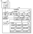
- FIG. 1 is a diagram illustrating a schematic configuration example of a secondary battery diagnostic system according to a first embodiment of the present technology.
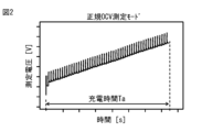
- FIG. 2 is a diagram showing an example of a measured voltage waveform obtained in the normal OCV measurement mode.
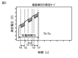
- FIG. 3 is a diagram showing an example of a measured voltage waveform obtained in the diagnosed OCV measurement mode.
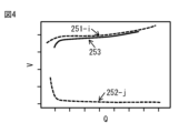
- FIG. 4 is a diagram showing an example of an OCV curve of a secondary battery in a normal state obtained by measurement, and an example of OCP curves of the positive electrode and the negative electrode read out from the memory unit in FIG.
- FIG. 5 is a diagram showing an example of a plurality of deterioration OCV curves when a secondary battery deteriorates under various conditions.
- FIG. 1 is a diagram illustrating a schematic configuration example of a secondary battery diagnostic system according to a first embodiment of the present technology.
- FIG. 2 is a diagram showing an example of a measured voltage waveform obtained in the normal OCV measurement mode.
- FIG. 3 is a diagram
- FIG. 6 is a diagram showing an example of the concept of a similarity table stored in the storage unit of FIG.
- FIG. 7 is a diagram showing an example of a plurality of dQ/dV-V curves obtained from the plurality of deteriorated OCV curves of FIG.
- FIG. 8 is a diagram showing an example of a deterioration diagnosis procedure for the charge/discharge device of FIG.
- FIG. 9 is a diagram illustrating a schematic configuration example of a secondary battery diagnostic system according to a second embodiment of the present technology.
- FIG. 10 is a diagram illustrating an example of a schematic configuration of the server device of FIG.
- FIG. 11 is a diagram illustrating a schematic configuration example of a secondary battery diagnostic system according to a third embodiment of the present technology.
- FIG. 12 is a diagram showing an example of a schematic configuration of the diagnostic device shown in FIG.
- First embodiment An example of diagnosing deterioration of a secondary battery in a charge/discharge device (FIGS. 1 to 8) 2.
- Second embodiment Example of diagnosis of deterioration of secondary batteries in a server device on a network (Figs. 9 and 10) 3.
- Third embodiment An example in which a diagnostic device provided between a charging/discharging device and a secondary battery performs a deterioration diagnosis of the secondary battery (FIGS. 11 and 12)
- FIG. 1 shows a schematic configuration example of the secondary battery diagnostic system according to the first embodiment of the present technology.
- the secondary battery diagnostic system according to the present embodiment includes, for example, a secondary battery pack 100 and a charging/discharging device 200 capable of charging and discharging the secondary battery pack 100, as shown in Fig. 1.
- the charging/discharging device 200 is a stand-alone device that does not have a function of communicating with an external device.
- the secondary battery pack 100 includes a secondary battery 110, for example, as shown in FIG. 1.
- the charging/discharging device 200 not only has the function of charging and discharging the secondary battery 110, but also has the function of diagnosing deterioration of the secondary battery 110.
- the secondary battery 110 is a lithium-ion secondary battery.
- the lithium-ion secondary battery included in the secondary battery 110 may be a unit cell, a battery block in which a number of unit cells are connected, or an assembled battery in which a battery block and accessories are integrally packed. In an assembled battery, a number of lithium-ion secondary batteries are connected in series. The assembled battery may also include a number of lithium-ion secondary batteries electrically connected in parallel.
- the charging/discharging device 200 includes, for example, a charging/discharging circuit 210, a charging/discharging control circuit 220, an IV measurement circuit 230, a processing unit 240, a memory unit 250, and a display unit 260, as shown in FIG. 1.
- the charge/discharge circuit 210 has a charge circuit that charges the secondary battery 110, and a discharge circuit that discharges the secondary battery 110.
- the charge circuit includes, for example, a generator and a converter.
- the charge/discharge control circuit 220 is capable of controlling the current for charging the secondary battery 110, and controlling the current for discharging the secondary battery 110.
- the charge/discharge control circuit 220 is configured, for example, by an MPU (Micro-Processing Unit) that performs charge/discharge control, or a CPU (Central Processing Unit) into which a charge/discharge control program is loaded.
- MPU Micro-Processing Unit
- CPU Central Processing Unit
- the charge/discharge control circuit 220 is capable of performing charge control in accordance with a charge mode control signal input from the processing unit 240. For example, when a signal indicating a "normal OCV (Open Circuit Voltage) measurement mode" is input from the processing unit 240 as a charge mode control signal, the charge/discharge control circuit 220 is capable of controlling the charge/discharge circuit 210 to discharge the secondary battery 110 to a predetermined voltage (first voltage) and then intermittently charge the secondary battery 110 to a predetermined voltage (second voltage higher than the first voltage).
- a predetermined voltage first voltage
- second voltage higher than the first voltage second voltage higher than the first voltage
- the charge/discharge control circuit 220 is capable of controlling the charge/discharge circuit 210 to discharge the secondary battery 110 to a predetermined voltage (first voltage) and then charge the secondary battery 110 to a predetermined voltage (second voltage higher than the first voltage).
- the charge/discharge control circuit 220 is capable of controlling the charge/discharge circuit 210 to perform intermittent charging in the OCV measurement section from the first voltage to the second voltage, and to perform continuous charging in sections other than the OCV measurement section.
- the charge/discharge circuit 210 is capable of applying an intermittent current (multiple constant current pulses) to the secondary battery 110 for intermittently charging the secondary battery 110.
- the width of the constant current pulse is, for example, a size corresponding to data about the current pulse width included in the charge mode control signal, e.g., 30 seconds.
- the period of the constant current pulse is, for example, a size corresponding to data about the constant current pulse period included in the charge mode control signal, e.g., 1 minute.
- the charge/discharge circuit 210 is capable of setting the OCV measurement period, for example, based on intermittent period data 256 included in the charge mode control signal.
- Figure 2 shows an example of an intermittent charging waveform obtained by measuring the voltage of the secondary battery 110 with the IV measurement circuit 230 when an intermittent current is applied to the secondary battery 110 from the charge/discharge circuit 210 in the "normal OCV measurement mode."
- the intermittent charging waveform shown in Figure 2 when a constant current pulse is applied to the secondary battery 110, the measured voltage rises in response, and when the application of the constant current pulse to the secondary battery 110 is stopped, the measured voltage decreases in response, the rate at which the measured voltage decreases gradually becomes more gradual, and the measured voltage becomes a constant value.
- FIG. 3 shows an example of a charging waveform obtained by measuring the voltage of the secondary battery 110 with the IV measurement circuit 230 when an intermittent current is applied from the charge/discharge circuit 210 to the secondary battery 110 in the OCV measurement section and a continuous current is applied in a section other than the OCV measurement section (continuous charging section) in the "diagnosed OCV measurement mode".
- the charging waveform shown in FIG. 3 when a constant current is applied to the secondary battery 110 in a section other than the OCV measurement section, the measured voltage rises in response. Also, in the charging waveform shown in FIG.
- times ta to tb, tc to td, and te to tf correspond to the OCV measurement interval, and the other intervals correspond to the continuous charging interval.
- the time required to charge from the first voltage to the second voltage in the "diagnosed OCV measurement mode” (charging time Tb) is shorter than the time required to charge from the first voltage to the second voltage in the "regular OCV measurement mode” (charging time Ta). This is because the total period during which the application of the constant current pulse is stopped is smaller in the "diagnosed OCV measurement mode" than in the "regular OCV measurement mode.”
- the IV measurement circuit 230 includes a measurement circuit that measures the current flowing through the secondary battery 110 and the voltage between the terminals of the secondary battery 110.
- the current flowing through the secondary battery 110 is referred to as the current of the secondary battery 110.
- the voltage between the terminals of the secondary battery 110 is referred to as the voltage of the secondary battery 110.
- the IV measurement circuit 230 is capable of measuring the current and voltage of the secondary battery 110 during discharging of the secondary battery 110 (while the secondary battery 110 is discharged to a first voltage) and during charging of the secondary battery 110 (while the secondary battery 110 is charged from the first voltage to a second voltage).
- the IV measurement circuit 230 is capable of outputting the current value obtained by measurement in the measurement circuit and the voltage value obtained by measurement in the measurement circuit to the processing unit 240.
- the processing unit 240 is configured, for example, by at least one CPU or a circuit including at least one semiconductor integrated circuit. As shown in FIG. 1, the processing unit 240 has, for example, a charging mode setting unit 241, an OCV acquisition unit 242, an OCP (Open Circuit Potential) analysis unit 243, a deterioration OCV estimation unit 244, an intermittent interval determination unit 245, and a deterioration diagnosis unit 246.
- a charging mode setting unit 241 an OCV acquisition unit 242
- OCP Open Circuit Potential
- the storage unit 250 is composed of a non-volatile memory such as a flash memory.
- the storage unit 250 stores, for example, a positive electrode OCP-DB 251 and a negative electrode OCP-DB 252.
- the positive electrode OCP-DB 251 includes a plurality of positive electrode OCP data for different positive electrode materials.
- the negative electrode OCP-DB 252 includes a plurality of negative electrode OCP data for different negative electrode materials.
- the storage unit 250 stores data obtained by processing in the processing unit 240 (for example, normal OCV data 253, similarity table 254, virtual OCV data 255, intermittent section data 256, deteriorated OCV data 257, measured OCV data 258, and deterioration diagnosis data 259).
- the intermittent section data 256 includes, for example, data on the OCV measurement section described below.
- the charge mode setting unit 241 is capable of outputting a signal indicating the "normal OCV measurement mode” or the "diagnosed OCV measurement mode” to the charge/discharge control circuit 220 as a charge mode control signal.
- the charge mode setting unit 241 is capable of outputting, for example, a flag indicating the "normal OCV measurement mode” and data regarding the current pulse width and the current pulse period to the charge/discharge control circuit 220 as a charge mode control signal.
- the charge mode setting unit 241 is capable of outputting, for example, a flag indicating the "diagnosed OCV measurement mode” and data regarding the current pulse width and the current pulse period to the charge/discharge control circuit 220 as a charge mode control signal.
- the OCV acquisition unit 242 is capable of acquiring normal OCV data 253 (see FIG. 4) on the OCV of the secondary battery 110 (first secondary battery) in the normal state based on the voltage value obtained by measurement in the IV measurement circuit 230.
- the secondary battery 110 in the normal state is referred to as the secondary battery 110a.
- the "normal state” refers to a state in which the deterioration state of the electrodes, etc. of the secondary battery 110 is within the range of the expected design value (i.e., the normal state).
- the OCV acquisition unit 242 is capable of acquiring data (measured OCV data 258) on the OCV of the secondary battery 110 (second secondary battery) of the same type as the secondary battery 110a based on the voltage value obtained by measurement in the IV measurement circuit 230.
- the "same type” refers to a secondary battery formed of the same structure and material as the secondary battery 100a.
- secondary battery 110b the same type of secondary battery 110 as secondary battery 110a will be referred to as secondary battery 110b.
- any positive electrode OCP data is assumed to be positive electrode OCP data 251-i (see FIG. 4).
- any negative electrode OCP data is assumed to be negative electrode OCP data 252-j (see FIG. 4).
- the OCP analysis unit 243 is capable of generating multiple pieces of virtual OCV data 255 (see FIG. 5) from a combination of any piece of positive electrode OCP data 251-i and any piece of negative electrode OCP data 252-j.
- the OCP analysis unit 243 is capable of storing the multiple pieces of virtual OCV data 255 generated in the memory unit 250.
- "Virtual OCV data 255" indicates that it is not obtained by measuring an actual secondary battery, but is OCV data of a virtual secondary battery composed of a positive electrode having the characteristics described in positive electrode OCP data 251-i and a negative electrode having the characteristics described in negative electrode OCP data 252-j.
- the OCP analysis unit 243 is capable of comparing the generated virtual OCV data 255 with the normal OCV data 253 and selecting, from the virtual OCV data 255, specific OCV data that can approximate the normal OCV data 253.
- the OCP analysis unit 243 is capable of selecting, for example, a combination of positive electrode OCP data 251-i and negative electrode OCP data 252-j that can approximate the normal OCV data 253 from the positive electrode OCP-DB 251 and the negative electrode OCP-DB 252.
- the OCP analysis unit 243 may be capable of setting the residual calculated at certain i and j as the minimum value of the residual.
- the OCP analysis unit 243 may be capable of, for example, storing in the memory unit 250 the residuals obtained for each combination of i and j as similarities and corresponding them to each combination of i and j as a similarity table 254 (see FIG. 6 ).
- the OCP analysis unit 243 may be capable of searching for a combination of a positive electrode OCP data group and a negative electrode OCP data group that can best reproduce the normal OCV data 253, for example, by using the following formula (2).
- one group (positive electrode OCP data group) is composed of a plurality of positive electrode OCP data
- one group (negative electrode OCP data group) is composed of a plurality of negative electrode OCP data.
- i is a serial number of a plurality of positive electrode OCP data groups included in the positive electrode OCP-DB 251
- j is a serial number of a plurality of negative electrode OCP data groups included in the negative electrode OCP-DB 252.
- the OCP analysis unit 243 may be capable of setting the Residual calculated at a certain i, j as the minimum value of the Residual, for example, when the Residual calculated at a certain i, j is smaller than the minimum value of the Residual calculated in the past.
- the degraded OCV estimation unit 244 is capable of estimating multiple degraded OCV data 257 when the secondary battery 110a in a normal state degrades under various conditions, based on the positive electrode OCP data 251-i and the negative electrode OCP data 251-j that can best reproduce the normal OCV data 253.
- the intermittent interval determination unit 245 is capable of determining an OCV measurement interval for measuring the OCV of the secondary battery 110b based on a plurality of pieces of degraded OCV data 257 obtained by the degraded OCV estimation unit 244.
- the intermittent interval determination unit 245 is capable of deriving a dQ/dV-V data group (see FIG. 7) from each piece of degraded OCV data 257 that indicates the relationship between the terminal voltage of the secondary battery 110b and the value obtained by dividing the charge capacity of the secondary battery 110b by the terminal voltage of the secondary battery 110b.
- La, Lb, and Lc are line segments connecting the minimum points of the curved valley regions in the multiple pieces of degraded OCV data 257
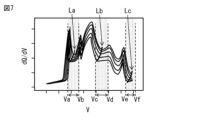
- FIG. 7 shows three voltage intervals (Va-Vb, Vc-Vd, and Ve-Vf) as voltage intervals that include curved valley regions.
- "Curved” means that the line segments La, Lb, and Lc are not straight, but curved.
- the sensitivity to voltage is more variable than other voltage intervals in the multiple pieces of degraded OCV data 257.
- the above-mentioned three voltage intervals (Va-Vb, Vc-Vd, and Ve-Vf) are voltage intervals in which the OCV shape changes sharply depending on the degraded state of the battery.
- the intermittent interval determination unit 245 can, for example, determine a voltage interval corresponding to a curved valley region included in the derived dQ/dV-V data group as the OCV measurement interval.
- the intermittent interval determination unit 245 can, for example, store the OCV measurement interval derived in this manner in the intermittent interval data 256 of the storage unit 250.
- the intermittent interval data 256 stores, for example, data on three voltage intervals (Va-Vb, Vc-Vd, Ve-Vf) as data on the OCV measurement interval.
- the deterioration diagnosis unit 246 is capable of performing deterioration diagnosis of the secondary battery 110b based on the diagnosed OCV data 258 of the secondary battery 110b acquired by the OCV acquisition unit 242.
- the display unit 260 is capable of displaying the results of the deterioration diagnosis in the deterioration diagnosis unit 246.
- FIG. 8 shows an example of a procedure for diagnosing deterioration of the secondary battery 110 in the charging/discharging device 200.
- the user connects the secondary battery pack 100 including the secondary battery 110a in a normal state to the charging/discharging device 200.
- the user instructs the charging/discharging device 200 to perform a normal OCV measurement.
- the processing unit 240 outputs a signal indicating the normal OCV measurement mode to the charging/discharging control circuit 220 as a charging mode control signal.
- the charging/discharging control circuit 220 performs control on the charging/discharging circuit 210 according to the signal indicating the normal OCV measurement mode input from the processing unit 240.
- the charging/discharging circuit 210 discharges the secondary battery 110a in a normal state to a predetermined voltage (first voltage) (step S101).
- the charging/discharging circuit 210 performs intermittent charging of the secondary battery 110a from the predetermined voltage (first voltage) to the predetermined voltage (second voltage) (step S102).
- step S102 the IV measurement circuit 230 measures the current and voltage of the secondary battery 110a and outputs the measurement values (current value and voltage value) obtained thereby to the processing unit 240.
- the processing unit 240 generates normal OCV data 253 based on the measurement values obtained from the IV measurement circuit 230 and stores it in the memory unit 250 (step S102).
- the processing unit 240 reproduces the normal OCV data 253 using the positive electrode OCP-DB 251 and the negative electrode OCP-DB 252 (step S103).
- the processing unit 240 generates a plurality of virtual OCV data 255, for example, from a combination of any positive electrode OCP data 251-i read from the positive electrode OCP-DB 251 and any negative electrode OCP data 252-j read from the negative electrode OCP-DB 252.
- the processing unit 240 compares the generated plurality of virtual OCV data 255 with the normal OCV data 253, for example, and selects, from the plurality of virtual OCV data 255, specific OCV data that can approximate the normal OCV data 253.
- the processing unit 240 for example, selects, from among a plurality of virtual OCV data 255, virtual OCV data 255 that can approximate the normal OCV data 253 as specific OCV data.
- the processing unit 240 estimates multiple pieces of degraded OCV data 257 when the secondary battery 110a in a normal state is degraded under various conditions based on the positive electrode OCP data 251-i and the negative electrode OCP data 251-j that can best reproduce the normal OCV data 253 (step S104).
- the processing unit 240 determines an OCV measurement section for measuring the OCV of the secondary battery 110b based on the multiple pieces of degraded OCV data 257 obtained by the degraded OCV estimation unit 244 (step S105).
- the processing unit 240 derives a group of dQ/dV-V data from each degraded OCV data 257 that indicates the relationship between the terminal voltage of the secondary battery 110b and the value obtained by dividing the charge capacity of the secondary battery 110b by the terminal voltage of the secondary battery 110b. For example, the processing unit 240 determines the voltage section corresponding to the curved valley region included in the derived dQ/dV-V data group as the OCV measurement section.
- the user connects the secondary battery pack 100 including the secondary battery 110a to the charging/discharging device 200. Then, the user instructs the charging/discharging device 200 to perform a diagnosed OCV measurement. Then, the processing unit 240 outputs a signal indicating the diagnosed OCV measurement mode to the charging/discharging control circuit 220 as a charging mode control signal.
- the charging/discharging control circuit 220 performs control on the charging/discharging circuit 210 according to the signal indicating the diagnosed OCV measurement mode input from the processing unit 240.
- the charging/discharging circuit 210 discharges the secondary battery 110b to a predetermined voltage (first voltage) (step S106).
- the charging/discharging circuit 210 intermittently charges the secondary battery 110b from the predetermined voltage (first voltage) to a predetermined voltage (second voltage) (step S107).
- step S107 the IV measurement circuit 230 measures the current and voltage of the secondary battery 110b and outputs the measurement values (current value and voltage value) obtained thereby to the processing unit 240.
- the processing unit 240 generates OCV data (diagnosed OCV data 258) of the secondary battery 110b based on the measurement values obtained from the IV measurement circuit 230 and stores it in the memory unit 250 (step S107).
- the processing unit 240 then performs a deterioration diagnosis of the secondary battery 110b based on the diagnosed OCV data 258, and causes the display unit 260 to display the result (deterioration diagnosis data 259). In this manner, a deterioration diagnosis of the secondary battery 110 in the charging/discharging device 200 is performed.
- specific OCV data capable of approximating the normal OCV data 253 is selected from among a plurality of virtual OCV data 255 obtained from a plurality of positive electrode OCP data and a plurality of negative electrode OCP data stored in the memory unit 250.
- OCP data of the positive and negative electrodes of the secondary battery 110a in the normal state positive electrode OCP data and negative electrode OCP data from which the specific OCV data can be obtained.
- multiple pieces of deteriorated OCV data 257 are estimated based on the positive electrode OCP data and the negative electrode OCP data from which specific OCV data is obtained when the secondary battery 110a in a normal state deteriorates under various conditions, and the OCV measurement section for measuring the OCV of the secondary battery 110b is determined based on the multiple pieces of deteriorated OCV data 257 obtained by estimation.
- intermittent charging is performed only during the OCV measurement section, and diagnosed OCV data 258 for the secondary battery 110b is obtained based on the terminal voltage of the secondary battery 110b obtained during the OCV measurement section.
- the diagnosed OCV data 258 for the secondary battery 110b can be obtained without always performing intermittent charging during charging, and the diagnosed OCV data 258 can be obtained in a short time. From the above, in this embodiment, even if the active material used in the secondary battery is not known in advance, deterioration diagnosis of the secondary battery can be performed without impairing usability.
- the virtual OCV data 255 that can approximate the normal OCV data 253 is selected as the specific OCV data. This makes it possible to obtain OCP data for the positive and negative electrodes of the secondary battery 110a in the normal state (positive electrode OCP data and negative electrode OCP data from which the specific OCV data can be obtained) even if the active materials of the positive and negative electrodes of the secondary battery 110a in the normal state are unknown.
- a dQ/dV-V data group is derived from each of the deteriorated OCV data 257, which indicates the relationship between the terminal voltage of the secondary battery 110b and the value obtained by dividing the charge capacity of the secondary battery 110b by the terminal voltage of the secondary battery 110b. Furthermore, the voltage section corresponding to the curved valley region included in the derived dQ/dV-V data group becomes the OCV measurement section.
- intermittent charging is performed only in the OCV measurement section, and diagnosed OCV data 258 for the secondary battery 110b can be obtained based on the terminal voltage of the secondary battery 110b obtained in the OCV measurement section.
- the diagnosed OCV data 258 for the secondary battery 110b can be obtained without always performing intermittent charging during charging, and therefore the diagnosed OCV data 258 can be obtained in a short time.
- the charge/discharge circuit 210 and the charge/discharge control circuit 220 are provided in the charge/discharge device 200. This allows the charge/discharge device 200 alone to obtain the diagnosed OCV data 258.
- FIG. 9 shows a schematic configuration example of the secondary battery diagnostic system according to the second embodiment of the present technology.
- the secondary battery diagnostic system according to the present embodiment includes, for example, a secondary battery pack 100, a charging/discharging device 300 capable of charging/discharging the secondary battery pack 100, and a server device 400, as shown in FIG. 9.
- the charging/discharging device 300 and the server device 400 are capable of communicating with each other via a network 500.
- the network 500 includes, for example, the Internet, a cloud network, or a network specific to a business operator.
- the charging/discharging device 300 includes a charging/discharging circuit 210, a charging/discharging control circuit 220, an IV measurement circuit 230, a processing unit 310, a communication unit 320, and a display unit 260.
- the processing unit 310 is configured, for example, by at least one CPU or a circuit including at least one semiconductor integrated circuit.
- the processing unit 310 is capable of transmitting time series data of the measurement values obtained from the IV measurement circuit 230 to the server device 400 via the communication unit 320.
- the communication unit 320 is a communication interface capable of communicating with the server device 400 via the network 500.
- FIG. 10 shows an example of the schematic configuration of the server device 400.
- the server device 400 includes a processing unit 240, a memory unit 250, and a communication unit 410.
- the communication unit 410 is a communication interface capable of communicating with the charging/discharging device 300 via the network 500.
- the processing unit 240 is capable of performing a deterioration diagnosis of the secondary battery 110b based on the time series data of the measurement values acquired via the communication unit 410 and the positive electrode OCP-DB 251 and negative electrode OCP-DB 252 of the memory unit 250.
- the deterioration diagnosis of the secondary battery 110b is performed by the server device 400.
- This allows the computational processing power of the charging/discharging device 300 to be kept low, making it possible to use a general-purpose device as the charging/discharging device 300. As a result, the cost of the charging/discharging device 300 can be kept low.
- Fig. 11 shows a schematic configuration example of the secondary battery diagnostic system according to the third embodiment of the present technology.
- the secondary battery diagnostic system according to the present embodiment includes, for example, a secondary battery pack 100, a charging/discharging device 600 capable of charging/discharging the secondary battery pack 100, and a diagnostic device 700, as shown in Fig. 11.
- the charging/discharging device 600 includes, for example, a charging/discharging circuit 210 and a charging/discharging control circuit 220, as shown in FIG. 11.
- the charging/discharging circuit 210 is capable of applying a continuous current to the secondary battery 110.
- the charging/discharging control circuit 220 is capable of controlling charging of the charging/discharging circuit 210 so that a continuous current is output from the charging/discharging circuit 210.
- the diagnostic device 700 includes a switching circuit 710, an IV measurement circuit 230, a processing unit 240, a memory unit 250, and a display unit 260.
- the switching circuit 710 is a circuit that can switch the electrical connection between the charge/discharge circuit 210 and the secondary battery 110.
- the processing unit 240 has, for example, a connection/disconnection control unit 247, a charging mode setting unit 241, an OCV acquisition unit 242, an OCP analysis unit 243, a deteriorated OCV estimation unit 244, an intermittent interval determination unit 245, and a deterioration diagnosis unit 246, as shown in FIG. 12.
- the charging mode setting unit 241 is capable of outputting a signal indicating the "normal OCV measurement mode” or the "diagnosed OCV measurement mode” to the on-off control unit 247 as a charging mode control signal.
- the charging mode setting unit 241 is capable of outputting, for example, a flag indicating the "normal OCV measurement mode” and data regarding the current pulse width and the current pulse period to the on-off control unit 247 as a charging mode control signal.
- the charging mode setting unit 241 is capable of outputting, for example, a flag indicating the "diagnosed OCV measurement mode” and data regarding the current pulse width and the current pulse period, and the intermittent section data 256 read out from the memory unit 250 to the on-off control unit 247 as a charging mode control signal.
- the on/off control unit 247 When the charge/discharge circuit 210 is continuously charging the secondary battery 110, the on/off control unit 247 outputs a control signal to the on/off circuit 710, and is capable of causing the on/off circuit 710 to make and break the electrical connection between the charge/discharge circuit 210 and the secondary battery 110. This enables the charge/discharge circuit 210 to perform intermittent charging of the secondary battery 110 by the on/off circuit 710 making and breaking the electrical connection between the charge/discharge circuit 210 and the secondary battery 110.
- the on-off control unit 247 is capable of performing on-off control according to a charge mode control signal input from the charge mode setting unit 241. For example, when a signal indicating "normal OCV measurement mode" is input as a charge mode control signal from the charge mode setting unit 241, the on-off control unit 247 is capable of controlling the on-off circuit 710 so that the secondary battery 110 is discharged to a predetermined voltage (first voltage) and then intermittently charged to a predetermined voltage (second voltage higher than the first voltage).
- the on-off control unit 247 is capable of controlling the on-off circuit 710 so that the secondary battery 110 is discharged to a predetermined voltage (first voltage) and then intermittently charged to a predetermined voltage (second voltage higher than the first voltage) in the OCV measurement section and continuously charged in sections other than the OCV measurement section.
- a switching circuit 710 is provided between the charge/discharge circuit 210 and the secondary battery 110, and a switching control unit 247 is provided to control the switching of the switching circuit 710. This allows the use of an inexpensive device that can only output continuous current as the charge/discharge device 600.
- the present technology can also be configured as follows.
- a storage unit that stores normal OCV (Open Circuit Voltage) data on an OCV of a first secondary battery in a normal state, a plurality of positive electrode OCP (Open Circuit Potential) data each having a different positive electrode material, and a plurality of negative electrode OCP data each having a different negative electrode material;
- a processing unit that performs processing based on the normal OCV data, the plurality of positive electrode OCP data, and the plurality of negative electrode OCP data read from the storage unit,
- the processing unit includes: an analysis unit that compares a plurality of virtual OCV data obtained by combining any one of the plurality of positive electrode OCP data read from the storage unit and any one of the plurality of negative electrode OCP data read from the storage unit with the normal OCV data, and selects, from the plurality of virtual OCV data, specific OCV data that can approximate the normal OCV data; an estimation unit that estimates a plurality of pieces of deterioration OCV data when the first secondary battery is
- the determination unit derives a dQ/dV-V data group from each of the deteriorated OCV data, and sets a voltage section corresponding to a curved valley region included in the derived dQ/dV-V data group as the OCV measurement section.
- a charging circuit that charges the second secondary battery by performing the intermittent charging and the continuous charging in a section other than the OCV measurement section;
- the secondary battery diagnostic system according to ⁇ 1> or ⁇ 2>, further comprising: a measurement circuit that measures a terminal voltage of the second secondary battery in the OCV measurement section.
- ⁇ 4> a communication unit capable of communicating with a charging device including a charging circuit that charges the second secondary battery by performing the intermittent charging and the continuous charging in a section other than the OCV measurement section, and a measurement circuit that measures a terminal voltage of the second secondary battery in the OCV measurement section;
- the secondary battery diagnostic system according to ⁇ 1> or ⁇ 2>, wherein the acquisition unit acquires the diagnosed OCV data based on a terminal-to-terminal voltage of the second secondary battery obtained via the communication unit.
- ⁇ 5> a measurement circuit that measures a terminal voltage of the second secondary battery in the OCV measurement section;
Landscapes
- Physics & Mathematics (AREA)
- General Physics & Mathematics (AREA)
- Engineering & Computer Science (AREA)
- Manufacturing & Machinery (AREA)
- Chemical & Material Sciences (AREA)
- Chemical Kinetics & Catalysis (AREA)
- Electrochemistry (AREA)
- General Chemical & Material Sciences (AREA)
- Secondary Cells (AREA)
- Charge And Discharge Circuits For Batteries Or The Like (AREA)
Abstract
本技術の一実施の形態に係る二次電池診断システムは、正規状態の第1の二次電池の正規OCVデータに基づいて、複数の正極OCPデータおよび複数の負極OCPデータから得られた複数の仮想OCVデータの中から、正規OCVデータを近似することが可能な特定OCVデータを選択する。この二次電池診断システムは、さらに、特定OCVデータが得られる正極OCPデータおよび負極OCPデータに基づいて、第1の二次電池が様々な条件で劣化した時の複数の劣化OCPデータを推定し、第2の二次電池のOCVを測定するためのOCV測定区間を、推定により得られた複数の劣化OCPデータに基づいて決定する。
Description
本技術は、二次電池診断システムおよび二次電池診断方法に関する。
リチウムイオン二次電池の使用用途の拡大に伴い、原料となるリチウムやコバルトなどの天然資源の枯渇が問題となってきている。この問題を解決する一つの方法として、リチウムイオン二次電池をその製品寿命が全うされるまで繰り返し再利用する方法が考えられる。効率よく二次利用する上で、一次利用を終了した時点の二次電池の劣化状態を適切に把握し、かつ、その劣化状態に合わせた二次利用を行うことが重要となる。
二次電池の劣化状態を診断する方法について、例えば、特許文献1~3に開示されている。
ところで、二次電池に使用される活物質が事前に分からない場合には、二次電池の正極および負極のOCP(Open Circuit Potential)を測定することが必要となる。しかし、OCP測定には膨大な時間を要するため、個々の二次電池の劣化診断を行う度にOCP測定を行うことは、ユーザビリティを損なってしまう。従って、二次電池に使用される活物質が事前に分からない場合であっても、ユーザビリティを損なうことなく二次電池の劣化診断を行うことを可能にする二次電池診断システムおよび二次電池診断方法を提供することが望ましい。
本技術の第1の側面に係る二次電池診断システムは、記憶部および処理部を備える。記憶部は、正規状態の第1の二次電池のOCV(Open Circuit Voltage)についての正規OCVデータと、正極材料が互いに異なる複数の正極OCP(Open Circuit Potential)データと、負極材料が互いに異なる複数の負極OCPデータとを記憶する。処理部は、解析部、推定部、決定部、取得部および診断部を有する。解析部は、記憶部から読み出した複数の正極OCPデータのうちの、任意の正極OCPデータと、記憶部から読み出した複数の負極OCPデータのうち、任意の負極OCPデータとの組み合わせから得られる複数の仮想OCVデータと、正規OCVデータとを対比して、複数の仮想OCVデータの中から、正規OCVデータを近似することが可能な特定OCVデータを選択する。推定部は、解析部で選択された特定OCVデータが得られる正極OCPデータおよび負極OCPデータに基づいて、第1の二次電池が様々な条件で劣化した時の複数の劣化OCVデータを推定する。決定部は、第1の二次電池と同種の第2の二次電池のOCVを測定するためのOCV測定区間を、推定部で得られた複数の劣化OCVデータに基づいて決定する。取得部は、第2の二次電池に対して、決定部で得られたOCV測定区間に間欠充電が行われるとともに、OCV測定区間以外の区間に連続充電が行われることにより、第2の二次電池が充電されるとともに、第2の二次電池についての被診断OCVデータを取得する。診断部は、取得部で得られた被診断OCVデータに基づいて、第2の二次電池の劣化診断を行うことが可能となっている。
本技術の第2の側面に係る二次電池診断方法は、以下の5つを含む。
(1)正極材料が互いに異なる複数の正極OCP(Open Circuit Potential)データのうちの、任意の正極OCPデータと、負極材料が互いに異なる複数の負極OCPデータのうち、任意の負極OCPデータとの組み合わせから得られる複数の仮想OCVデータと、正規状態の第1の二次電池のOCV(Open Circuit Voltage)についての正規OCVデータとを対比して、複数の仮想OCVデータの中から、正規OCVデータを近似することが可能な特定OCVデータを選択すること
(2)選択した特定OCVデータが得られる正極OCPデータおよび負極OCPデータに基づいて、第1の二次電池が様々な条件で劣化した時の複数の劣化OCVデータを推定すること
(3)第1の二次電池と同種の第2の二次電池のOCVを測定するためのOCV測定区間を、推定部で得られた複数の劣化OCVデータに基づいて決定すること
(4)第2の二次電池に対して、OCV測定区間に間欠充電を行うとともに、OCV測定区間以外の区間に連続充電を行うことにより、第2の二次電池の充電を行うとともに、第2の二次電池についての被診断OCVデータを取得すること
(5)被診断OCVデータに基づいて、第2の二次電池の劣化診断を行うこと
(1)正極材料が互いに異なる複数の正極OCP(Open Circuit Potential)データのうちの、任意の正極OCPデータと、負極材料が互いに異なる複数の負極OCPデータのうち、任意の負極OCPデータとの組み合わせから得られる複数の仮想OCVデータと、正規状態の第1の二次電池のOCV(Open Circuit Voltage)についての正規OCVデータとを対比して、複数の仮想OCVデータの中から、正規OCVデータを近似することが可能な特定OCVデータを選択すること
(2)選択した特定OCVデータが得られる正極OCPデータおよび負極OCPデータに基づいて、第1の二次電池が様々な条件で劣化した時の複数の劣化OCVデータを推定すること
(3)第1の二次電池と同種の第2の二次電池のOCVを測定するためのOCV測定区間を、推定部で得られた複数の劣化OCVデータに基づいて決定すること
(4)第2の二次電池に対して、OCV測定区間に間欠充電を行うとともに、OCV測定区間以外の区間に連続充電を行うことにより、第2の二次電池の充電を行うとともに、第2の二次電池についての被診断OCVデータを取得すること
(5)被診断OCVデータに基づいて、第2の二次電池の劣化診断を行うこと
本技術の第1の側面に係る二次電池診断システム、および、本技術の第2の側面に係る二次電池診断方法では、正規状態の第1の二次電池の正規OCVデータに基づいて、複数の正極OCPデータおよび複数の負極OCPデータから得られた複数の仮想OCVデータの中から、正規OCVデータを近似することが可能な特定OCVデータが選択される。これにより、正規状態の第1の二次電池において正極および負極の活物質が未知の場合であっても、正規状態の第1の二次電池の正極および負極のOCPデータ(特定OCVデータが得られる正極OCPデータおよび負極OCPデータ)が得られる。また、本技術では、特定OCVデータが得られる正極OCPデータおよび負極OCPデータに基づいて、第1の二次電池が様々な条件で劣化した時の複数の劣化OCVデータが推定され、第1の二次電池と同種の第2の二次電池のOCVを測定するためのOCV測定区間が、推定により得られた複数の劣化OCVデータに基づいて決定される。本技術では、さらに、OCV測定区間だけ間欠充電を行うとともに、OCV測定区間以外の区間に連続充電を行うことにより、第2の二次電池の充電が行われるとともに、第2の二次電池についての被診断OCVデータが得られる。これにより、充電時に常に間欠充電を行わなくても、第2の二次電池についての被診断OCVデータが得られるので、短時間で被診断OCVデータが得られる。以上のことから、本技術では、二次電池に使用される活物質が事前に分からない場合であっても、ユーザビリティを損なうことなく二次電池の劣化診断を行うことができる。
なお、本技術の効果は、必ずしもここで説明された効果に限定されるわけではなく、後述する本技術に関連する一連の効果のうちのいずれの効果でもよい。
以下、本技術を実施するための形態について、図面を参照して詳細に説明する。なお、説明する順序は、下記の通りである。
1.第1の実施形態
充放電装置において二次電池の劣化診断を行う例(図1~図8)
2.第2の実施形態
ネットワーク上のサーバ装置において二次電池の劣化診断を
行う例(図9、図10)
3.第3の実施形態
充放電装置と二次電池との間に設けた診断装置において
二次電池の劣化診断を行う例(図11、図12)
1.第1の実施形態
充放電装置において二次電池の劣化診断を行う例(図1~図8)
2.第2の実施形態
ネットワーク上のサーバ装置において二次電池の劣化診断を
行う例(図9、図10)
3.第3の実施形態
充放電装置と二次電池との間に設けた診断装置において
二次電池の劣化診断を行う例(図11、図12)
<1.第1の実施形態>
[構成]
本技術の第1の実施形態に係る二次電池診断システムの構成について説明する。図1は、本技術の第1の実施形態に係る二次電池診断システムの概略構成例を表したものである。本実施の形態に係る二次電池診断システムは、例えば、図1に示したように、二次電池パック100と、二次電池パック100を充放電することの可能な充放電装置200とを備える。充放電装置200は、外部の装置と通信する機能を有しないスタンドアロン型の装置である。
[構成]
本技術の第1の実施形態に係る二次電池診断システムの構成について説明する。図1は、本技術の第1の実施形態に係る二次電池診断システムの概略構成例を表したものである。本実施の形態に係る二次電池診断システムは、例えば、図1に示したように、二次電池パック100と、二次電池パック100を充放電することの可能な充放電装置200とを備える。充放電装置200は、外部の装置と通信する機能を有しないスタンドアロン型の装置である。
二次電池パック100は、例えば、図1に示したように、二次電池110を備える。充放電装置200は、二次電池110を充放電する機能だけでなく、二次電池110の劣化診断を行う機能も備える。
二次電池110は、リチウムイオン二次電池である。二次電池110に含まれるリチウムイオン二次電池は、単位セルであってもよく、単位セルが複数個接続された電池ブロック、もしくは、電池ブロックおよび付属品が一体的にパッキングされた組電池であってもよい。組電池では、複数のリチウムイオン二次電池が直列に接続されている。組電池内において、電気的に並列に接続された複数のリチウムイオン二次電池が含まれていてもよい。
次に、充放電装置200の構成について説明する。
充放電装置200は、例えば、図1に示したように、充放電回路210、充放電制御回路220、IV計測回路230、処理部240、記憶部250および表示部260を備える。
充放電回路210は、二次電池110を充電する充電回路や、二次電池110を放電させる放電回路を有する。充電回路は、例えば発電機およびコンバータ等を含む。充放電制御回路220は、二次電池110を充電するための電流を制御したり、二次電池110を放電させるための電流を制御したりすることが可能となっている。充放電制御回路220は、例えば、充放電制御を行うMPU(Micro-Processing Unit)、または、充放電制御プログラムがロードされたCPU(Central Processing Unit)によって構成されている。
充放電制御回路220は、処理部240から入力される充電モード制御信号に従った充電制御を行うことが可能となっている。充放電制御回路220は、例えば、処理部240から充電モード制御信号として「正規OCV(Open Circuit Voltage)測定モード」を示す信号が入力されると、二次電池110を所定の電圧(第1電圧)まで放電した後、所定の電圧(第1電圧よりも高い第2電圧)まで間欠充電するように充放電回路210を制御することが可能となっている。充放電制御回路220は、例えば、処理部240から充電モードとして「被診断OCV測定モード」を示す信号が入力されると、二次電池110を、所定の電圧(第1電圧)まで放電した後、所定の電圧(第1電圧よりも高い第2電圧)になるまで、充電するように充放電回路210を制御することが可能となっている。ここで、充放電制御回路220は、被診断OCV測定モードにおいて、第1電圧から第2電圧までの区間において、OCV測定区間に間欠充電を行うとともに、OCV測定区間以外の区間に連続充電を行うように充放電回路210を制御することが可能となっている。
充放電回路210は、例えば、二次電池110を間欠充電させるための間欠電流(複数の定電流パルス)を二次電池110に印加することが可能となっている。間欠電流において、定電流パルスの幅は、例えば、充電モード制御信号に含まれる電流パルス幅についてのデータに応じた大きさとなっており、例えば30秒となっている。また、間欠電流において、定電流パルスの周期は、例えば、充電モード制御信号に含まれる定電流パルス周期についてのデータに応じた大きさとなっており、例えば1分となっている。充放電回路210は、例えば、充電モード制御信号に含まれる間欠区間データ256に基づいて、OCV測定区間を設定することが可能となっている。
図2は、「正規OCV測定モード」において、充放電回路210から二次電池110に間欠電流が印加されているときの、二次電池110の電圧をIV計測回路230で測定することにより得られた間欠充電波形の一例を表したものである。図2に示した間欠充電波形では、二次電池110に定電流パルスが印加されると、それに応答する形で測定電圧が上昇し、二次電池110への定電流パルスの印加が停止されると、それに応答する形で測定電圧が減少し、測定電圧の減少度合が徐々に緩やかになり、測定電圧が一定値となる。
図3は、「被診断OCV測定モード」において、充放電回路210から二次電池110に、OCV測定区間においては間欠電流が印加され、OCV測定区間以外の区間(連続充電区間)においては連続電流が印加されているときの、二次電池110の電圧をIV計測回路230で測定することにより得られた充電波形の一例を表したものである。図3に示した充電波形では、OCV測定区間以外の区間においては、二次電池110に定電流が印加されると、それに応答する形で測定電圧が上昇する。また、図3に示した充電波形では、OCV測定区間においては、二次電池110に定電流パルスが印加されると、それに応答する形で測定電圧が上昇し、二次電池110への定電流パルスの印加が停止されると、それに応答する形で測定電圧が減少し、測定電圧の減少度合が徐々に緩やかになり、測定電圧が一定値となる。
図3において、時刻ta~tb、時刻tc~td、時刻te~tfがOCV測定区間に対応する時間となっており、それ以外の区間が連続充電区間に対応する時間となっている。「被診断OCV測定モード」において第1電圧から第2電圧まで充電するのに要する時間(充電時間Tb)は、「正規OCV測定モード」において第1電圧から第2電圧まで充電するのに要する時間(充電時間Ta)よりも短くなっている。これは、「正規OCV測定モード」よりも「被診断OCV測定モード」の方が、定電流パルスの印加が停止される期間の合計値が小さいためである。
IV計測回路230は、二次電池110に流れる電流、および二次電池110の端子間の電圧を計測する計測回路を含む。以下、二次電池110に流れる電流を、二次電池110の電流と称する。また、二次電池110の端子間の電圧を、二次電池110の電圧と称する。IV計測回路230は、二次電池110に対する放電の間(二次電池110が第1電圧まで放電される間)と、二次電池110に対する充電の間(二次電池110が第1電圧から第2電圧まで充電される間)とにおいて、二次電池110の電流および電圧を計測することが可能となっている。IV計測回路230は、計測回路での測定により得られた電流値と、計測回路での測定により得られた電圧値とを処理部240に出力することが可能となっている。
処理部240は、例えば、少なくとも1つのCPU、または、少なくとも1つの半導体集積回路を含む回路によって構成されている。処理部240は、例えば、図1に示したように、充電モード設定部241、OCV取得部242、OCP(Open Circuit Potential)解析部243、劣化OCV推定部244、間欠区間決定部245および劣化診断部246を有する。
記憶部250は、例えば、フラッシュメモリなどの不揮発性メモリで構成される。記憶部250は、例えば、正極OCP-DB251および負極OCP-DB252を記憶している。正極OCP-DB251には、正極材料が互いに異なる複数の正極OCPデータが含まれる。負極OCP-DB252には、負極材料が互いに異なる複数の負極OCPデータが含まれる。記憶部250には、処理部240における処理により得られるデータ(例えば、正規OCVデータ253、類似度テーブル254、仮想OCVデータ255、間欠区間データ256、劣化OCVデータ257、計測OCVデータ258および劣化診断データ259)が記憶される。間欠区間データ256には、例えば、後述のOCV測定区間についてのデータが含まれる。
充電モード設定部241は、充電モード制御信号として、「正規OCV測定モード」もしくは「被診断OCV測定モード」を示す信号を充放電制御回路220に出力することが可能となっている。充電モード設定部241は、例えば、充電モード制御信号として、「正規OCV測定モード」を示すフラグと、電流パルス幅および電流パルス周期についてのデータとを充放電制御回路220に出力することが可能となっている。充電モード設定部241は、例えば、充電モード制御信号として、「被診断OCV測定モード」を示すフラグと、電流パルス幅および電流パルス周期についてのデータと、記憶部250から読み出した間欠区間データ256とを充放電制御回路220に出力することが可能となっている。
OCV取得部242は、「正規OCV測定モード」において、IV計測回路230での測定により得られた電圧値に基づいて、正規状態の二次電池110(第1の二次電池)のOCVについての正規OCVデータ253(図4参照)を取得することが可能となっている。以下、正規状態の二次電池110を二次電池110aと称する。「正規状態」とは、二次電池110の電極等の劣化状態が想定設計値の範囲内である状態(つまり通常状態)を指している。OCV取得部242は、「被診断OCV測定モード」において、IV計測回路230での測定により得られた電圧値に基づいて、二次電池110aと同種の二次電池110(第2の二次電池)のOCVについてのデータ(計測OCVデータ258)を取得することが可能となっている。「同種」とは、二次電池100aの構造および材料と共通の構造および材料で形成された二次電池を指している。以下、二次電池110aと同種の二次電池110を二次電池110bと称する。
記憶部250の正極OCP-DB251に含まれる複数の正極OCPデータのうちの、任意の正極OCPデータを正極OCPデータ251-iとする(図4参照)。また、記憶部250の負極OCP-DB252に含まれる複数の負極OCPデータのうち、任意の負極OCPデータを負極OCPデータ252-jとする(図4参照)。このとき、OCP解析部243は、任意の正極OCPデータ251-iおよび任意の負極OCPデータ252-jの組み合わせから、複数の仮想OCVデータ255(図5参照)を生成することが可能となっている。OCP解析部243は、生成した複数の仮想OCVデータ255を記憶部250に格納することが可能となっている。「仮想OCVデータ255」とは、実在の二次電池を計測することにより得られたものではなく、正極OCPデータ251-iで記述される特性を有する正極と、負極OCPデータ252-jで記述される特性を有する負極とによって構成された仮想的な二次電池のOCVデータであることを示している。
OCP解析部243は、生成した複数の仮想OCVデータ255と、正規OCVデータ253とを対比して、複数の仮想OCVデータ255の中から、正規OCVデータ253を近似することが可能な特定OCVデータを選択することが可能となっている。OCP解析部243は、例えば、正規OCVデータ253を近似することが可能な正極OCPデータ251-iおよび負極OCPデータ252-jの組み合わせを、正極OCP-DB251および負極OCP-DB252から選択することが可能となっている。
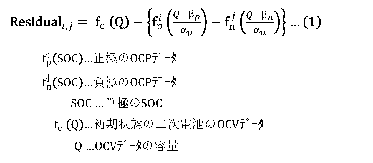
OCP解析部243は、例えば、以下の式(1)を用いて、正規OCVデータ253を最もよく再現することの可能な正極OCPデータ251-iおよび負極OCPデータ252-jの組み合わせを探索することが可能となっていてもよい。式(1)において、iは、正極OCP-DB251に含まれる複数の正極OCPデータの通し番号であり、jは、負極OCP-DB252に含まれる複数の負極OCPデータの通し番号である。式(1)のResidualが最小となるように、αp、βp、αn、βnが最適化されている。OCP解析部243は、例えば、あるi、jで算出したResidualが過去に算出したResidualの最小値よりも小さいとき、あるi、jで算出したResidualを、Residualの最小値として設定することが可能となっていてもよい。OCP解析部243は、例えば、i、jの組み合わせごとに得られたResidualを類似度として、i、jの組み合わせごとに対応付けたものを類似度テーブル254(図6参照)として、記憶部250に格納することが可能となっていてもよい。
OCP解析部243は、例えば、以下の式(2)を用いて、正規OCVデータ253を最もよく再現することの可能な正極OCPデータグループおよび負極OCPデータグループの組み合わせを探索することが可能となっていてもよい。式(2)において、複数の正極OCPデータによって1つのグループ(正極OCPデータグループ)が構成されており、複数の負極OCPデータによって1つのグループ(負極OCPデータグループ)が構成されている。iは、正極OCP-DB251に含まれる複数の正極OCPデータグループの通し番号であり、jは、負極OCP-DB252に含まれる複数の負極OCPデータグループの通し番号である。式(2)のResidualが最小となるように、αp、βp、αn、βnが最適化されている。OCP解析部243は、例えば、あるi、jで算出したResidualが過去に算出したResidualの最小値よりも小さいとき、あるi、jで算出したResidualを、Residualの最小値として設定することが可能となっていてもよい。
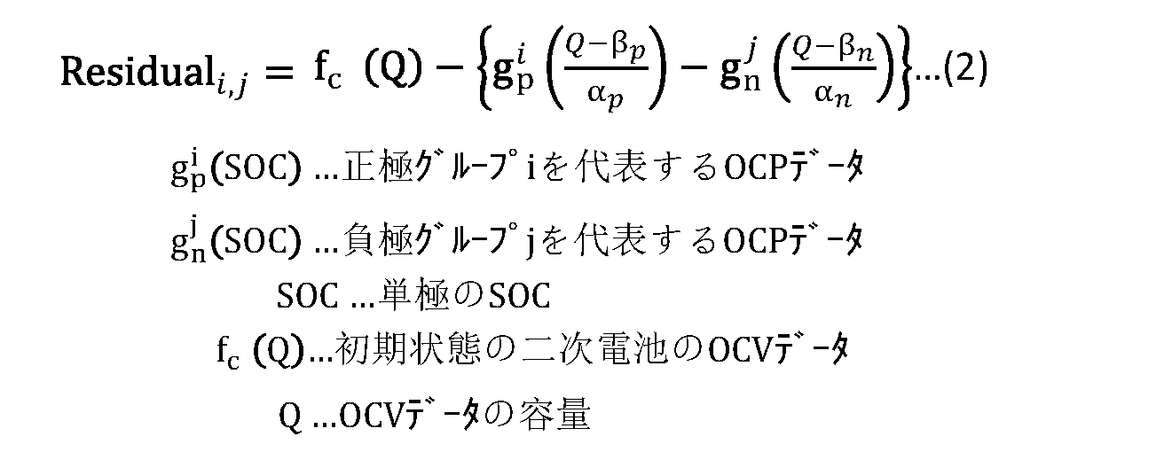
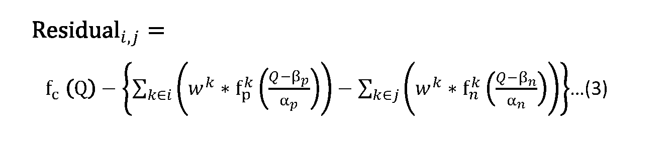
OCP解析部243は、例えば、以下の式(3)を用いて、正極OCPデータグループごとに、グループ内の複数の正極OCPデータを重み付け平均し、負極OCPデータグループごとに、グループ内の複数の負極OCPデータを重み付け平均することが可能となっていてもよい。式(3)において、wは重み係数である。kは、グループ内の複数のOCPデータの通し番号である。OCP解析部243は、例えば、式(2)で用いたαp、βp、αn、βnをそのまま用い、あるi、jで算出したResidualが過去に算出したResidualの最小値よりも小さいとき、あるi、jで算出したResidualを、Residualの最小値として設定することが可能となっていてもよい。
劣化OCV推定部244は、正規OCVデータ253を最もよく再現することの可能な正極OCPデータ251-iタおよび負極OCPデータ251-jに基づいて、正規状態の二次電池110aが様々な条件で劣化した時の複数の劣化OCVデータ257を推定することが可能となっている。
間欠区間決定部245は、二次電池110bのOCVを測定するためのOCV測定区間を、劣化OCV推定部244で得られた複数の劣化OCVデータ257に基づいて決定することが可能となっている。間欠区間決定部245は、例えば、各劣化OCVデータ257から、二次電池110bの端子間電圧と、二次電池110bの充電容量を二次電池110bの端子間電圧で割った値との関係を示すdQ/dV-Vデータ群(図7参照)を導出することが可能となっている。
図7において、La,Lb,Lcは、複数の劣化OCVデータ257において湾曲した谷領域の最小値点を結んだ線分であり、図7には、湾曲した谷領域を含む電圧区間として、3つの電圧区間(Va~Vb、Vc~Vd、Ve~Vf)が例示されている。「湾曲した」とは、線分La,Lb,Lcが直線状になっておらず、曲がっていることを指している。上述の3つの電圧区間(Va~Vb、Vc~Vd、Ve~Vf)では、複数の劣化OCVデータ257において、電圧に対する感度が他の電圧区間と比べて変化に富んでいる。つまり、上述の3つの電圧区間(Va~Vb、Vc~Vd、Ve~Vf)は電池の劣化状態に対してOCV形状が鋭敏に変化する電圧区間である。
間欠区間決定部245は、例えば、導出したdQ/dV-Vデータ群に含まれる、湾曲した谷領域に対応する電圧区間をOCV測定区間とすることが可能となっている。間欠区間決定部245は、例えば、このようにして導出したOCV測定区間を記憶部250の間欠区間データ256に格納することが可能となっている。間欠区間データ256には、例えば、OCV測定区間についてのデータとして、3つの電圧区間(Va~Vb、Vc~Vd、Ve~Vf)についてのデータが格納されている。
劣化診断部246は、OCV取得部242が取得した二次電池110bの被診断OCVデータ258に基づいて、二次電池110bの劣化診断を行うことが可能となっている。表示部260は、劣化診断部246における劣化診断の結果を表示することが可能となっている。
次に、本実施の形態に係る二次電池診断システムにおける二次電池110の劣化診断について説明する。
図8は、充放電装置200における二次電池110の劣化診断手順の一例を表したものである。まず、ユーザは、充放電装置200に対して、正規状態の二次電池110aを含む二次電池パック100を接続する。続いて、ユーザは、充放電装置200に対して、正規OCV測定の実行を指示する。すると、処理部240は、充電モード制御信号として、正規OCV測定モードを示す信号を充放電制御回路220に出力する。充放電制御回路220は、処理部240から入力された正規OCV測定モードを示す信号に応じた制御を充放電回路210に対して行う。その結果、まず、充放電回路210は、正規状態の二次電池110aを所定の電圧(第1電圧)まで放電する(ステップS101)。続いて、充放電回路210は、二次電池110aに対して、所定の電圧(第1電圧)から所定の電圧(第2電圧)まで間欠充電を行う(ステップS102)。
IV計測回路230は、ステップS102のとき、二次電池110aの電流および電圧を計測し、それにより得られた計測値(電流値および電圧値)を処理部240に出力する。処理部240は、IV計測回路230から得られた計測値に基づいて、正規OCVデータ253を生成し、記憶部250に格納する(ステップS102)。
次に、処理部240は、正極OCP-DB251および負極OCP-DB252を用いて、正規OCVデータ253を再現する(ステップS103)。処理部240は、例えば、正極OCP-DB251から読み出した任意の正極OCPデータ251-iと、負極OCP-DB252から読み出した任意の負極OCPデータ252-jとの組み合わせから、複数の仮想OCVデータ255を生成する。処理部240は、例えば、生成した複数の仮想OCVデータ255と、正規OCVデータ253とを対比して、複数の仮想OCVデータ255の中から、正規OCVデータ253を近似することが可能な特定OCVデータを選択する。処理部240は、例えば、複数の仮想OCVデータ255の中から、正規OCVデータ253を近似することが可能な仮想OCVデータ255を、特定OCVデータとして選択する。
次に、処理部240は、正規OCVデータ253を最もよく再現することの可能な正極OCPデータ251-iタおよび負極OCPデータ251-jに基づいて、正規状態の二次電池110aが様々な条件で劣化した時の複数の劣化OCVデータ257を推定する(ステップS104)。続いて、処理部240は、二次電池110bのOCVを測定するためのOCV測定区間を、劣化OCV推定部244で得られた複数の劣化OCVデータ257に基づいて決定する(ステップS105)。処理部240は、例えば、各劣化OCVデータ257から、二次電池110bの端子間電圧と、二次電池110bの充電容量を二次電池110bの端子間電圧で割った値との関係を示すdQ/dV-Vデータ群を導出する。処理部240は、例えば、導出したdQ/dV-Vデータ群に含まれる、湾曲した谷領域に対応する電圧区間をOCV測定区間とする。
次に、ユーザは、充放電装置200に対して、二次電池110aを含む二次電池パック100を接続する。続いて、ユーザは、充放電装置200に対して、被診断OCV測定の実行を指示する。すると、処理部240は、充電モード制御信号として、被診断OCV測定モードを示す信号を充放電制御回路220に出力する。充放電制御回路220は、処理部240から入力された被診断OCV測定モードを示す信号に応じた制御を充放電回路210に対して行う。その結果、まず、充放電回路210は、二次電池110bを所定の電圧(第1電圧)まで放電する(ステップS106)。続いて、充放電回路210は、二次電池110bに対して、所定の電圧(第1電圧)から所定の電圧(第2電圧)まで、間欠充電を断続的に行う(ステップS107)。
IV計測回路230は、ステップS107のとき、二次電池110bの電流および電圧を計測し、それにより得られた計測値(電流値および電圧値)を処理部240に出力する。処理部240は、IV計測回路230から得られた計測値に基づいて、二次電池110bのOCVデータ(被診断OCVデータ258)を生成し、記憶部250に格納する(ステップS107)。その後、処理部240は、被診断OCVデータ258に基づいて、二次電池110bの劣化診断を行い、その結果(劣化診断データ259)を表示部260に表示させる。このようにして、充放電装置200における二次電池110の劣化診断が行われる。
[効果]
次に、本実施の形態に係る二次電池診断システムの効果について説明する。
次に、本実施の形態に係る二次電池診断システムの効果について説明する。
本実施の形態では、正規状態の二次電池110aの正規OCVデータ253に基づいて、記憶部250に格納された複数の正極OCPデータおよび複数の負極OCPデータから得られた複数の仮想OCVデータ255の中から、正規OCVデータ253を近似することが可能な特定OCVデータが選択される。これにより、正規状態の二次電池110aにおいて正極および負極の活物質が未知の場合であっても、正規状態の二次電池110aの正極および負極のOCPデータ(特定OCVデータが得られる正極OCPデータおよび負極OCPデータ)を得ることができる。
また、本実施の形態では、特定OCVデータが得られる正極OCPデータおよび負極OCPデータに基づいて、正規状態の二次電池110aが様々な条件で劣化した時の複数の劣化OCVデータ257が推定され、二次電池110bのOCVを測定するためのOCV測定区間が、推定により得られた複数の劣化OCVデータ257に基づいて決定される。本実施の形態では、さらに、OCV測定区間だけ間欠充電を行い、OCV測定区間に得られた二次電池110bの端子間電圧に基づいて、二次電池110bについての被診断OCVデータ258が得られる。これにより、充電時に常に間欠充電を行わなくても、二次電池110bについての被診断OCVデータ258が得られるので、短時間で被診断OCVデータ258を得ることができる。以上のことから、本実施の形態では、二次電池に使用される活物質が事前に分からない場合であっても、ユーザビリティを損なうことなく二次電池の劣化診断を行うことができる。
本実施の形態では、複数の仮想OCVデータ255の中から、正規OCVデータ253を近似することが可能な仮想OCVデータ255が、特定OCVデータとして選択される。これにより、正規状態の二次電池110aにおいて正極および負極の活物質が未知の場合であっても、正規状態の二次電池110aの正極および負極のOCPデータ(特定OCVデータが得られる正極OCPデータおよび負極OCPデータ)を得ることができる。
本実施の形態では、各劣化OCVデータ257から、二次電池110bの端子間電圧と、二次電池110bの充電容量を二次電池110bの端子間電圧で割った値との関係を示すdQ/dV-Vデータ群が導出される。さらに、導出されたdQ/dV-Vデータ群に含まれる、湾曲した谷領域に対応する電圧区間がOCV測定区間となる。これにより、OCV測定区間だけ間欠充電を行い、OCV測定区間に得られた二次電池110bの端子間電圧に基づいて、二次電池110bについての被診断OCVデータ258を得ることができる。その結果、充電時に常に間欠充電を行わなくても、二次電池110bについての被診断OCVデータ258が得られるので、短時間で被診断OCVデータ258を得ることができる。
本実施の形態では、充放電回路210および充放電制御回路220が充放電装置200に設けられている。これにより、充放電装置200単体で、被診断OCVデータ258を得ることができる。
<2.第2の実施形態>
次に、本技術の第2の実施形態に係る二次電池診断システムの構成について説明する。図9は、本技術の第2の実施形態に係る二次電池診断システムの概略構成例を表したものである。本実施の形態に係る二次電池診断システムは、例えば、図9に示したように、二次電池パック100と、二次電池パック100を充放電することの可能な充放電装置300と、サーバ装置400とを備える。充放電装置300およびサーバ装置400は、ネットワーク500を介して互いに通信可能となっている。ネットワーク500は、例えば、インターネット、クラウドネットワーク、または、事業者固有のネットワークなどを含んで構成されている。
次に、本技術の第2の実施形態に係る二次電池診断システムの構成について説明する。図9は、本技術の第2の実施形態に係る二次電池診断システムの概略構成例を表したものである。本実施の形態に係る二次電池診断システムは、例えば、図9に示したように、二次電池パック100と、二次電池パック100を充放電することの可能な充放電装置300と、サーバ装置400とを備える。充放電装置300およびサーバ装置400は、ネットワーク500を介して互いに通信可能となっている。ネットワーク500は、例えば、インターネット、クラウドネットワーク、または、事業者固有のネットワークなどを含んで構成されている。
充放電装置300は、例えば、図9に示したように、充放電回路210、充放電制御回路220、IV計測回路230、処理部310、通信部320および表示部260を備える。処理部310は、例えば、少なくとも1つのCPU、または、少なくとも1つの半導体集積回路を含む回路によって構成されている。処理部310は、IV計測回路230から得られた計測値の時系列データを、通信部320を介してサーバ装置400に送信することが可能となっている。通信部320は、ネットワーク500を介してサーバ装置400と通信を行うことの可能な通信インターフェースである。
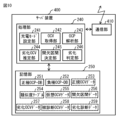
図10は、サーバ装置400の概略構成例を表したものである。サーバ装置400は、例えば、図10に示したように、処理部240、記憶部250および通信部410を備える。通信部410は、ネットワーク500を介して充放電装置300と通信を行うことの可能な通信インターフェースである。処理部240は、通信部410を介して取得した計測値の時系列データと、記憶部250の正極OCP-DB251および負極OCP-DB252とに基づいて、二次電池110bの劣化診断を行うことが可能となっている。
本実施の形態では、二次電池110bの劣化診断がサーバ装置400で行われる。これにより、充放電装置300での演算処理能力を低く抑えることができ、充放電装置300として汎用の装置を用いることが可能となる。その結果、充放電装置300のコストを低く抑えることができる。
<3.第3の実施形態>
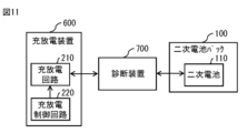
次に、本技術の第3の実施形態に係る二次電池診断システムの構成について説明する。図11は、本技術の第3の実施形態に係る二次電池診断システムの概略構成例を表したものである。本実施の形態に係る二次電池診断システムは、例えば、図11に示したように、二次電池パック100と、二次電池パック100を充放電することの可能な充放電装置600と、診断装置700とを備える。
次に、本技術の第3の実施形態に係る二次電池診断システムの構成について説明する。図11は、本技術の第3の実施形態に係る二次電池診断システムの概略構成例を表したものである。本実施の形態に係る二次電池診断システムは、例えば、図11に示したように、二次電池パック100と、二次電池パック100を充放電することの可能な充放電装置600と、診断装置700とを備える。
充放電装置600は、例えば、図11に示したように、充放電回路210および充放電制御回路220を備える。充放電回路210は、連続電流を二次電池110に印加することが可能となっている。充放電制御回路220は、充放電回路210から連続電流が出力されるように充放電回路210に対する充電制御を行うことが可能となっている。
診断装置700は、例えば、図12に示したように、継断回路710、IV計測回路230、処理部240、記憶部250および表示部260を備える。継断回路710は、充放電回路210と二次電池110との電気的な接続を継断することの可能な回路である。
処理部240は、例えば、図12に示したように、継断制御部247、充電モード設定部241、OCV取得部242、OCP解析部243、劣化OCV推定部244、間欠区間決定部245および劣化診断部246を有する。
充電モード設定部241は、充電モード制御信号として、「正規OCV測定モード」もしくは「被診断OCV測定モード」を示す信号を継断制御部247に出力することが可能となっている。充電モード設定部241は、例えば、充電モード制御信号として、「正規OCV測定モード」を示すフラグと、電流パルス幅および電流パルス周期についてのデータとを継断制御部247に出力することが可能となっている。充電モード設定部241は、例えば、充電モード制御信号として、「被診断OCV測定モード」を示すフラグと、電流パルス幅および電流パルス周期についてのデータと、記憶部250から読み出した間欠区間データ256とを継断制御部247に出力することが可能となっている。
継断制御部247は、充放電回路210が二次電池110に対して連続充電を行っている時に、継断回路710に対して制御信号を出力し、継断回路710に対して、充放電回路210と二次電池110との電気的な接続を継断させることが可能となっている。これにより、充放電回路210は、継断回路710による充放電回路210と二次電池110との電気的な接続の継断により、二次電池110に対して間欠充電を行うことが可能となっている。
継断制御部247は、充電モード設定部241から入力される充電モード制御信号に従った継断制御を行うことが可能となっている。継断制御部247は、例えば、充電モード設定部241から充電モード制御信号として「正規OCV測定モード」を示す信号が入力されると、二次電池110が所定の電圧(第1電圧)まで放電された後、所定の電圧(第1電圧よりも高い第2電圧)まで間欠充電されるように継断回路710を制御することが可能となっている。継断制御部247は、例えば、充電モード設定部241から充電モードとして「被診断OCV測定モード」を示す信号が入力されると、二次電池110が所定の電圧(第1電圧)まで放電された後、所定の電圧(第1電圧よりも高い第2電圧)になるまで、OCV測定区間に間欠充電が行われるとともに、OCV測定区間以外の区間に連続充電が行われるように継断回路710を制御することが可能となっている。
本実施の形態では、充放電回路210と二次電池110との間に継断回路710が設けられ、さらに、継断回路710の継断を制御する継断制御部247が設けられている。これにより、充放電装置600として、連続電流だけしか出力できないような安価な装置を用いることができる。
なお、本技術は、以下のような構成を取ることもできる。
<1>
正規状態の第1の二次電池のOCV(Open Circuit Voltage)についての正規OCVデータと、正極材料が互いに異なる複数の正極OCP(Open Circuit Potential)データと、負極材料が互いに異なる複数の負極OCPデータとを記憶する記憶部と、
前記記憶部から読み出した前記正規OCVデータ、前記複数の正極OCPデータおよび前記複数の負極OCPデータに基づいた処理を行う処理部と
を備え、
前記処理部は、
前記記憶部から読み出した前記複数の正極OCPデータのうちの、任意の前記正極OCPデータと、前記記憶部から読み出した前記複数の負極OCPデータのうち、任意の前記負極OCPデータとの組み合わせから得られる複数の仮想OCVデータと、前記正規OCVデータとを対比して、前記複数の仮想OCVデータの中から、前記正規OCVデータを近似することが可能な特定OCVデータを選択する解析部と、
前記解析部で選択された前記特定OCVデータが得られる前記正極OCPデータおよび前記負極OCPデータに基づいて、前記第1の二次電池が様々な条件で劣化した時の複数の劣化OCVデータを推定する推定部と、
前記第1の二次電池と同種の第2の二次電池のOCVを測定するためのOCV測定区間を、前記推定部で得られた前記複数の劣化OCVデータに基づいて決定する決定部と、
前記第2の二次電池に対して、前記決定部で得られた前記OCV測定区間に間欠充電が行われるとともに、前記OCV測定区間以外の区間に連続充電が行われることにより、前記第2の二次電池が充電されるとともに、前記第2の二次電池についての被診断OCVデータを取得する取得部と、
前記取得部で得られた前記被診断OCVデータに基づいて、前記第2の二次電池の劣化診断を行う診断部と
を有する
二次電池診断システム。
<2>
前記決定部は、各前記劣化OCVデータから、dQ/dV-Vデータ群を導出し、導出した前記dQ/dV-Vデータ群に含まれる、湾曲した谷領域に対応する電圧区間を前記OCV測定区間とする
<1>に記載の二次電池診断システム。
<3>
前記第2の二次電池に対して、前記間欠充電を行うとともに、前記OCV測定区間以外の区間に前記連続充電を行うことにより、前記第2の二次電池の充電を行う充電回路と、
前記OCV測定区間における前記第2の二次電池の端子間電圧を計測する計測回路と
を更に備えた
<1>または<2>に記載の二次電池診断システム。
<4>
前記第2の二次電池に対して、前記間欠充電を行うとともに、前記OCV測定区間以外の区間に前記連続充電を行うことにより、前記第2の二次電池の充電を行う充電回路と、前記OCV測定区間における前記第2の二次電池の端子間電圧を計測する計測回路とを備えた充電装置と通信可能な通信部を更に備え、
前記取得部は、前記通信部を介して得られた前記第2の二次電池の端子間電圧に基づいて、前記被診断OCVデータを取得する
<1>または<2>に記載の二次電池診断システム。
<5>
前記OCV測定区間における前記第2の二次電池の端子間電圧を計測する計測回路と、
前記第2の二次電池に対して、前記間欠充電を行うとともに、前記OCV測定区間以外の区間に前記連続充電を行うことにより、前記第2の二次電池の充電を行う充電回路と、前記第2の二次電池との電気的な接続を継断する継断回路と
を更に備えた
<1>または<2>に記載の二次電池診断システム。
<6>
正極材料が互いに異なる複数の正極OCP(Open Circuit Potential)データのうちの、任意の前記正極OCPデータと、負極材料が互いに異なる複数の負極OCPデータのうち、任意の前記負極OCPデータとの組み合わせから得られる複数の仮想OCVデータと、正規状態の第1の二次電池のOCV(Open Circuit Voltage)についての正規OCVデータとを対比して、前記複数の仮想OCVデータの中から、前記正規OCVデータを近似することが可能な特定OCVデータを選択することと、
選択した前記特定OCVデータが得られる前記正極OCPデータおよび前記負極OCPデータに基づいて、前記第1の二次電池が様々な条件で劣化した時の複数の劣化OCVデータを推定することと、
前記第1の二次電池と同種の第2の二次電池のOCVを測定するためのOCV測定区間を、前記推定部で得られた前記複数の劣化OCVデータに基づいて決定することと、
前記第2の二次電池に対して、前記OCV測定区間に間欠充電を行うとともに、前記OCV測定区間以外の区間に連続充電を行うことにより、前記第2の二次電池の充電を行うとともに、前記第2の二次電池についての被診断OCVデータを取得することと、
前記被診断OCVデータに基づいて、前記第2の二次電池の劣化診断を行うことと
を含む
二次電池診断方法。
<1>
正規状態の第1の二次電池のOCV(Open Circuit Voltage)についての正規OCVデータと、正極材料が互いに異なる複数の正極OCP(Open Circuit Potential)データと、負極材料が互いに異なる複数の負極OCPデータとを記憶する記憶部と、
前記記憶部から読み出した前記正規OCVデータ、前記複数の正極OCPデータおよび前記複数の負極OCPデータに基づいた処理を行う処理部と
を備え、
前記処理部は、
前記記憶部から読み出した前記複数の正極OCPデータのうちの、任意の前記正極OCPデータと、前記記憶部から読み出した前記複数の負極OCPデータのうち、任意の前記負極OCPデータとの組み合わせから得られる複数の仮想OCVデータと、前記正規OCVデータとを対比して、前記複数の仮想OCVデータの中から、前記正規OCVデータを近似することが可能な特定OCVデータを選択する解析部と、
前記解析部で選択された前記特定OCVデータが得られる前記正極OCPデータおよび前記負極OCPデータに基づいて、前記第1の二次電池が様々な条件で劣化した時の複数の劣化OCVデータを推定する推定部と、
前記第1の二次電池と同種の第2の二次電池のOCVを測定するためのOCV測定区間を、前記推定部で得られた前記複数の劣化OCVデータに基づいて決定する決定部と、
前記第2の二次電池に対して、前記決定部で得られた前記OCV測定区間に間欠充電が行われるとともに、前記OCV測定区間以外の区間に連続充電が行われることにより、前記第2の二次電池が充電されるとともに、前記第2の二次電池についての被診断OCVデータを取得する取得部と、
前記取得部で得られた前記被診断OCVデータに基づいて、前記第2の二次電池の劣化診断を行う診断部と
を有する
二次電池診断システム。
<2>
前記決定部は、各前記劣化OCVデータから、dQ/dV-Vデータ群を導出し、導出した前記dQ/dV-Vデータ群に含まれる、湾曲した谷領域に対応する電圧区間を前記OCV測定区間とする
<1>に記載の二次電池診断システム。
<3>
前記第2の二次電池に対して、前記間欠充電を行うとともに、前記OCV測定区間以外の区間に前記連続充電を行うことにより、前記第2の二次電池の充電を行う充電回路と、
前記OCV測定区間における前記第2の二次電池の端子間電圧を計測する計測回路と
を更に備えた
<1>または<2>に記載の二次電池診断システム。
<4>
前記第2の二次電池に対して、前記間欠充電を行うとともに、前記OCV測定区間以外の区間に前記連続充電を行うことにより、前記第2の二次電池の充電を行う充電回路と、前記OCV測定区間における前記第2の二次電池の端子間電圧を計測する計測回路とを備えた充電装置と通信可能な通信部を更に備え、
前記取得部は、前記通信部を介して得られた前記第2の二次電池の端子間電圧に基づいて、前記被診断OCVデータを取得する
<1>または<2>に記載の二次電池診断システム。
<5>
前記OCV測定区間における前記第2の二次電池の端子間電圧を計測する計測回路と、
前記第2の二次電池に対して、前記間欠充電を行うとともに、前記OCV測定区間以外の区間に前記連続充電を行うことにより、前記第2の二次電池の充電を行う充電回路と、前記第2の二次電池との電気的な接続を継断する継断回路と
を更に備えた
<1>または<2>に記載の二次電池診断システム。
<6>
正極材料が互いに異なる複数の正極OCP(Open Circuit Potential)データのうちの、任意の前記正極OCPデータと、負極材料が互いに異なる複数の負極OCPデータのうち、任意の前記負極OCPデータとの組み合わせから得られる複数の仮想OCVデータと、正規状態の第1の二次電池のOCV(Open Circuit Voltage)についての正規OCVデータとを対比して、前記複数の仮想OCVデータの中から、前記正規OCVデータを近似することが可能な特定OCVデータを選択することと、
選択した前記特定OCVデータが得られる前記正極OCPデータおよび前記負極OCPデータに基づいて、前記第1の二次電池が様々な条件で劣化した時の複数の劣化OCVデータを推定することと、
前記第1の二次電池と同種の第2の二次電池のOCVを測定するためのOCV測定区間を、前記推定部で得られた前記複数の劣化OCVデータに基づいて決定することと、
前記第2の二次電池に対して、前記OCV測定区間に間欠充電を行うとともに、前記OCV測定区間以外の区間に連続充電を行うことにより、前記第2の二次電池の充電を行うとともに、前記第2の二次電池についての被診断OCVデータを取得することと、
前記被診断OCVデータに基づいて、前記第2の二次電池の劣化診断を行うことと
を含む
二次電池診断方法。
Claims (6)
- 正規状態の第1の二次電池のOCV(Open Circuit Voltage)についての正規OCVデータと、正極材料が互いに異なる複数の正極OCP(Open Circuit Potential)データと、負極材料が互いに異なる複数の負極OCPデータとを記憶する記憶部と、
前記記憶部から読み出した前記正規OCVデータ、前記複数の正極OCPデータおよび前記複数の負極OCPデータに基づいた処理を行う処理部と
を備え、
前記処理部は、
前記記憶部から読み出した前記複数の正極OCPデータのうちの、任意の前記正極OCPデータと、前記記憶部から読み出した前記複数の負極OCPデータのうち、任意の前記負極OCPデータとの組み合わせから得られる複数の仮想OCVデータと、前記正規OCVデータとを対比して、前記複数の仮想OCVデータの中から、前記正規OCVデータを近似することが可能な特定OCVデータを選択する解析部と、
前記解析部で選択された前記特定OCVデータが得られる前記正極OCPデータおよび前記負極OCPデータに基づいて、前記第1の二次電池が様々な条件で劣化した時の複数の劣化OCVデータを推定する推定部と、
前記第1の二次電池と同種の第2の二次電池のOCVを測定するためのOCV測定区間を、前記推定部で得られた前記複数の劣化OCVデータに基づいて決定する決定部と、
前記第2の二次電池に対して、前記決定部で得られた前記OCV測定区間に間欠充電が行われるとともに、前記OCV測定区間以外の区間に連続充電が行われることにより、前記第2の二次電池が充電されるとともに、前記第2の二次電池についての被診断OCVデータを取得する取得部と、
前記取得部で得られた前記被診断OCVデータに基づいて、前記第2の二次電池の劣化診断を行う診断部と
を有する
二次電池診断システム。 - 前記決定部は、各前記劣化OCVデータから、dQ/dV-Vデータ群を導出し、導出した前記dQ/dV-Vデータ群に含まれる、湾曲した谷領域に対応する電圧区間を前記OCV測定区間とする
請求項1に記載の二次電池診断システム。 - 前記第2の二次電池に対して、前記間欠充電を行うとともに、前記OCV測定区間以外の区間に前記連続充電を行うことにより、前記第2の二次電池の充電を行う充電回路と、
前記OCV測定区間における前記第2の二次電池の端子間電圧を計測する計測回路と
を更に備えた
請求項1または請求項2に記載の二次電池診断システム。 - 前記第2の二次電池に対して、前記間欠充電を行うとともに、前記OCV測定区間以外の区間に前記連続充電を行うことにより、前記第2の二次電池の充電を行う充電回路と、前記OCV測定区間における前記第2の二次電池の端子間電圧を計測する計測回路とを備えた充電装置と通信可能な通信部を更に備え、
前記取得部は、前記通信部を介して得られた前記第2の二次電池の端子間電圧に基づいて、前記被診断OCVデータを取得する
請求項1または請求項2に記載の二次電池診断システム。 - 前記OCV測定区間における前記第2の二次電池の端子間電圧を計測する計測回路と、
前記第2の二次電池に対して、前記間欠充電を行うとともに、前記OCV測定区間以外の区間に前記連続充電を行うことにより、前記第2の二次電池の充電を行う充電回路と、前記第2の二次電池との電気的な接続を継断する継断回路と
を更に備えた
請求項1または請求項2に記載の二次電池診断システム。 - 正極材料が互いに異なる複数の正極OCP(Open Circuit Potential)データのうちの、任意の前記正極OCPデータと、負極材料が互いに異なる複数の負極OCPデータのうち、任意の前記負極OCPデータとの組み合わせから得られる複数の仮想OCVデータと、正規状態の第1の二次電池のOCV(Open Circuit Voltage)についての正規OCVデータとを対比して、前記複数の仮想OCVデータの中から、前記正規OCVデータを近似することが可能な特定OCVデータを選択することと、
選択した前記特定OCVデータが得られる前記正極OCPデータおよび前記負極OCPデータに基づいて、前記第1の二次電池が様々な条件で劣化した時の複数の劣化OCVデータを推定することと、
前記第1の二次電池と同種の第2の二次電池のOCVを測定するためのOCV測定区間を、前記推定部で得られた前記複数の劣化OCVデータに基づいて決定することと、
前記第2の二次電池に対して、前記OCV測定区間に間欠充電を行うとともに、前記OCV測定区間以外の区間に連続充電を行うことにより、前記第2の二次電池の充電を行うとともに、前記第2の二次電池についての被診断OCVデータを取得することと、
前記被診断OCVデータに基づいて、前記第2の二次電池の劣化診断を行うことと
を含む
二次電池診断方法。
Applications Claiming Priority (2)
| Application Number | Priority Date | Filing Date | Title |
|---|---|---|---|
| JP2023203412 | 2023-11-30 | ||
| JP2023-203412 | 2023-11-30 |
Publications (1)
| Publication Number | Publication Date |
|---|---|
| WO2025115355A1 true WO2025115355A1 (ja) | 2025-06-05 |
Family
ID=95897565
Family Applications (1)
| Application Number | Title | Priority Date | Filing Date |
|---|---|---|---|
| PCT/JP2024/033463 Pending WO2025115355A1 (ja) | 2023-11-30 | 2024-09-19 | 二次電池診断システムおよび二次電池診断方法 |
Country Status (1)
| Country | Link |
|---|---|
| WO (1) | WO2025115355A1 (ja) |
Citations (8)
| Publication number | Priority date | Publication date | Assignee | Title |
|---|---|---|---|---|
| JP2009080093A (ja) * | 2007-09-07 | 2009-04-16 | Hitachi Vehicle Energy Ltd | 二次電池の内部情報検知方法及び装置 |
| JP2013247003A (ja) * | 2012-05-28 | 2013-12-09 | Sony Corp | 二次電池の充電制御装置、二次電池の充電制御方法、二次電池の充電状態推定装置、二次電池の充電状態推定方法、二次電池の劣化度推定装置、二次電池の劣化度推定方法、及び、二次電池装置 |
| JP2015087344A (ja) * | 2013-11-01 | 2015-05-07 | ソニー株式会社 | 容量劣化推定装置、蓄電装置および容量劣化推定方法 |
| US20190195956A1 (en) * | 2017-12-21 | 2019-06-27 | Samsung Electronics Co., Ltd. | Battery monitoring method and apparatus detecting charge balance of battery |
| JP2021092464A (ja) * | 2019-12-11 | 2021-06-17 | 株式会社日立製作所 | 電池データの調整方法及びバッテリマネージメントユニットの製造方法並びにバッテリマネージメントユニット及びサーバー |
| JP7287483B2 (ja) * | 2019-10-25 | 2023-06-06 | 株式会社村田製作所 | 蓄電装置および充放電の制御方法 |
| JP2023127623A (ja) * | 2022-03-02 | 2023-09-14 | 株式会社日立製作所 | 充電制御システム、充電制御方法、及びプログラム |
| JP2023131650A (ja) * | 2022-03-09 | 2023-09-22 | 株式会社日立製作所 | 状態診断装置および状態診断システム |
-
2024
- 2024-09-19 WO PCT/JP2024/033463 patent/WO2025115355A1/ja active Pending
Patent Citations (8)
| Publication number | Priority date | Publication date | Assignee | Title |
|---|---|---|---|---|
| JP2009080093A (ja) * | 2007-09-07 | 2009-04-16 | Hitachi Vehicle Energy Ltd | 二次電池の内部情報検知方法及び装置 |
| JP2013247003A (ja) * | 2012-05-28 | 2013-12-09 | Sony Corp | 二次電池の充電制御装置、二次電池の充電制御方法、二次電池の充電状態推定装置、二次電池の充電状態推定方法、二次電池の劣化度推定装置、二次電池の劣化度推定方法、及び、二次電池装置 |
| JP2015087344A (ja) * | 2013-11-01 | 2015-05-07 | ソニー株式会社 | 容量劣化推定装置、蓄電装置および容量劣化推定方法 |
| US20190195956A1 (en) * | 2017-12-21 | 2019-06-27 | Samsung Electronics Co., Ltd. | Battery monitoring method and apparatus detecting charge balance of battery |
| JP7287483B2 (ja) * | 2019-10-25 | 2023-06-06 | 株式会社村田製作所 | 蓄電装置および充放電の制御方法 |
| JP2021092464A (ja) * | 2019-12-11 | 2021-06-17 | 株式会社日立製作所 | 電池データの調整方法及びバッテリマネージメントユニットの製造方法並びにバッテリマネージメントユニット及びサーバー |
| JP2023127623A (ja) * | 2022-03-02 | 2023-09-14 | 株式会社日立製作所 | 充電制御システム、充電制御方法、及びプログラム |
| JP2023131650A (ja) * | 2022-03-09 | 2023-09-22 | 株式会社日立製作所 | 状態診断装置および状態診断システム |
Similar Documents
| Publication | Publication Date | Title |
|---|---|---|
| EP4191732B1 (en) | Battery management device, battery management method | |
| US10310024B2 (en) | Methods and apparatus for measuring battery characteristics | |
| CN107102263B (zh) | 检测电池健康状态的方法、装置和电池管理系统 | |
| JP6734784B2 (ja) | バッテリの健全性を推定する方法 | |
| EP1877812B1 (en) | Lithium sulfur rechargeable battery fuel gauge systems and methods | |
| CN112986841B (zh) | 电池荷电状态的估算方法、装置及设备 | |
| JP5474993B2 (ja) | 充電段階または放電段階において電池の充電状態を決定する方法 | |
| CN109671997A (zh) | 电子装置与充电方法 | |
| EP3505946A1 (en) | Battery state estimation device and battery state estimation method | |
| JP7169917B2 (ja) | 二次電池の制御装置及び二次電池の制御方法 | |
| JP2022044172A (ja) | 複数の電池に関する判定装置、蓄電システム、判定方法及び判定プログラム | |
| EP4653898A1 (en) | Battery diagnosis apparatus and battery diagnosis method | |
| JP4090713B2 (ja) | ニッケル水素電池の容量推定方法 | |
| CN120569637A (zh) | 电池诊断装置和电池诊断方法 | |
| JP2000133322A (ja) | 二次電池の充放電システム | |
| AU2020409573A1 (en) | Method for determining the value of a parameter related to the state of health of an electrochemical element in a battery, electronic management system for a battery, and corresponding battery | |
| EP4641237A1 (en) | Battery diagnosis method and battery diagnosis apparatus | |
| EP4729965A1 (en) | Battery diagnosis apparatus and battery diagnosis method | |
| EP4707835A1 (en) | Battery diagnosis apparatus and battery diagnosis method | |
| EP4729964A1 (en) | Battery diagnosis apparatus and battery diagnosis method | |
| EP4726417A1 (en) | Battery diagnosis apparatus and battery diagnosis method | |
| Brećko et al. | Proposed method for battery state estimation | |
| WO2025115365A1 (ja) | 二次電池評価システムおよび二次電池評価方法 | |
| JP2024118013A (ja) | 二次電池の分析方法、充電装置、二次電池分析装置および二次電池パック | |
| Mucko | A Possibility of the State of Charge Monitoring of the Lead-Acid Battery by Means of Current Pulses of a Given Value |
Legal Events
| Date | Code | Title | Description |
|---|---|---|---|
| 121 | Ep: the epo has been informed by wipo that ep was designated in this application |
Ref document number: 24897046 Country of ref document: EP Kind code of ref document: A1 |