WO2025104992A1 - クリップ - Google Patents
クリップ Download PDFInfo
- Publication number
- WO2025104992A1 WO2025104992A1 PCT/JP2024/029302 JP2024029302W WO2025104992A1 WO 2025104992 A1 WO2025104992 A1 WO 2025104992A1 JP 2024029302 W JP2024029302 W JP 2024029302W WO 2025104992 A1 WO2025104992 A1 WO 2025104992A1
- Authority
- WO
- WIPO (PCT)
- Prior art keywords
- piece
- clip
- hole
- tip
- pin
- Prior art date
- Legal status (The legal status is an assumption and is not a legal conclusion. Google has not performed a legal analysis and makes no representation as to the accuracy of the status listed.)
- Pending
Links
Images





Classifications
-
- F—MECHANICAL ENGINEERING; LIGHTING; HEATING; WEAPONS; BLASTING
- F16—ENGINEERING ELEMENTS AND UNITS; GENERAL MEASURES FOR PRODUCING AND MAINTAINING EFFECTIVE FUNCTIONING OF MACHINES OR INSTALLATIONS; THERMAL INSULATION IN GENERAL
- F16B—DEVICES FOR FASTENING OR SECURING CONSTRUCTIONAL ELEMENTS OR MACHINE PARTS TOGETHER, e.g. NAILS, BOLTS, CIRCLIPS, CLAMPS, CLIPS OR WEDGES; JOINTS OR JOINTING
- F16B21/00—Means for preventing relative axial movement of a pin, spigot, shaft or the like and a member surrounding it; Stud-and-socket releasable fastenings
- F16B21/06—Releasable fastening devices with snap-action
- F16B21/07—Releasable fastening devices with snap-action in which the socket has a resilient part
-
- F—MECHANICAL ENGINEERING; LIGHTING; HEATING; WEAPONS; BLASTING
- F16—ENGINEERING ELEMENTS AND UNITS; GENERAL MEASURES FOR PRODUCING AND MAINTAINING EFFECTIVE FUNCTIONING OF MACHINES OR INSTALLATIONS; THERMAL INSULATION IN GENERAL
- F16B—DEVICES FOR FASTENING OR SECURING CONSTRUCTIONAL ELEMENTS OR MACHINE PARTS TOGETHER, e.g. NAILS, BOLTS, CIRCLIPS, CLAMPS, CLIPS OR WEDGES; JOINTS OR JOINTING
- F16B19/00—Bolts without screw-thread; Pins, including deformable elements; Rivets
- F16B19/04—Rivets; Spigots or the like fastened by riveting
- F16B19/08—Hollow rivets; Multi-part rivets
- F16B19/10—Hollow rivets; Multi-part rivets fastened by expanding mechanically
-
- F—MECHANICAL ENGINEERING; LIGHTING; HEATING; WEAPONS; BLASTING
- F16—ENGINEERING ELEMENTS AND UNITS; GENERAL MEASURES FOR PRODUCING AND MAINTAINING EFFECTIVE FUNCTIONING OF MACHINES OR INSTALLATIONS; THERMAL INSULATION IN GENERAL
- F16B—DEVICES FOR FASTENING OR SECURING CONSTRUCTIONAL ELEMENTS OR MACHINE PARTS TOGETHER, e.g. NAILS, BOLTS, CIRCLIPS, CLAMPS, CLIPS OR WEDGES; JOINTS OR JOINTING
- F16B21/00—Means for preventing relative axial movement of a pin, spigot, shaft or the like and a member surrounding it; Stud-and-socket releasable fastenings
- F16B21/06—Releasable fastening devices with snap-action
- F16B21/08—Releasable fastening devices with snap-action in which the stud, pin, or spigot has a resilient part
Definitions
- the present invention relates to a clip having a grommet and a pin.
- Patent Document 1 discloses a clip for attaching a bumper retainer to a vehicle body.
- the clip has a grommet and a pin formed on the bumper retainer.
- the grommet has multiple locking claws that are inserted into a connecting hole formed in the vehicle body. When the pin is inserted into the grommet, the multiple locking claws are pushed by the pin and spread apart, locking the edges of the connecting hole. This connects the bumper retainer to the vehicle body.
- the grommet is made of a resin material with high rigidity (low toughness)
- the locking claws may undergo plastic deformation, reducing the adhesion between the locking claws and the connecting hole. This can lead to problems such as the grommet rattling or making abnormal noises.
- the present invention aims to provide a clip that can maintain an appropriate fastening state regardless of the material.
- a clip (1) is attached to a panel (3) having a connection hole (7), the clip (1) having a body portion (22) having a receiving hole (21), a grommet (15) having a plurality of locking claws (24) and a plurality of support pieces (25) extending from the periphery of the receiving hole in the body portion along the axis (A) of the receiving hole, and a pin (16) having a shaft portion (31) to be inserted into the receiving hole, the shaft
- the locking claws each have a large diameter portion (31A) provided on the base end side, and a small diameter portion (31B) provided on the tip side of the large diameter portion and having a smaller diameter than the large diameter portion, and the small diameter portion has a first engagement portion (33) provided on the tip side and a second engagement portion (34) provided on the large diameter portion side of the first engagement portion, and each of the locking claws has a first piece portion (24A) extending from the main body portion in parallel with the axis
- Each of the support pieces has a second piece (25A) extending from the main body in parallel with the axis of the receiving hole, and a locking protrusion (25B) protruding from the tip of the second piece toward the receiving hole.
- the pin can move relative to the grommet between a temporary locking position where each of the locking protrusions engages with the first engagement portion and a fastening position where each of the locking protrusions engages with the second engagement portion.
- each of the first pieces faces the small diameter portion with a gap between them, allowing it to be displaced toward the shaft portion.
- the pin is in the fastening position, each of the first pieces abuts against the large diameter portion, restricting displacement toward the shaft portion.
- a retaining piece (29) extending in the circumferential direction about the axis is provided at the tip of each of the second pieces.
- This aspect makes it possible to provide a clip that can maintain an appropriate fastening state regardless of the material.
- the locking claw When the pin is in the temporary fastening position, the locking claw can be displaced toward the shaft portion, so the locking claw can pass through the coupling hole.
- the locking claw cannot be displaced toward the shaft portion, so the locking claw is maintained in a state where it is locked into the coupling hole.
- the pin When the pin is in the fastening position, the locking claw is not deformed, so plastic deformation of the locking claw is suppressed.
- a gap is formed between the shaft portion and the locking claw, but the locking protrusions and retaining pieces of the multiple support pieces surround the shaft portion, so the shaft portion is suppressed from falling against the grommet.
- each of the holding pieces may be positioned farther from the main body portion than the tip of the first piece portion.
- the retaining piece can retain the shaft portion further toward the tip side than the first piece, and the shaft portion is more appropriately prevented from falling over relative to the grommet.
- the plurality of support pieces may include a pair of support pieces, and in a cross section perpendicular to the axis, the pair of retaining pieces may be arranged to form a frame shape surrounding the small diameter portion.
- This configuration more appropriately prevents the shaft from tipping over the grommet.
- the second piece may be inclined toward the shaft portion as it approaches the tip end, and the retaining piece may be positioned closer to the shaft portion than the base end of the second piece.
- the retaining piece can be brought closer to the shaft, which more appropriately prevents the shaft from falling over relative to the grommet.
- the second engagement portion may include a plurality of recesses (34A) arranged along the circumferential direction of the shaft portion, and the bottom of each of the recesses may be provided with an inclined surface (34B) whose depth decreases in the circumferential direction of the shaft portion.
- the shaft portion rotates, allowing the locking protrusion to slide along the inclined surface and disengage from the second engagement portion.
- a first cam (41) is provided on the outer peripheral surface of the base end of the shaft, and a second cam (42) that abuts against the first cam is provided on the main body, and when the shaft rotates in a predetermined rotational direction, each of the locking protrusions slides on the corresponding inclined surface and disengages from the recess, and the first cam and the second cam slide against each other to move the shaft in a direction disengaging from the receiving hole, and each of the retaining pieces may extend from the corresponding second piece in the rotational direction.
- This configuration prevents the tip of the retaining piece from getting caught on the shaft.
- the main body of the grommet may be integrally formed with a bracket that supports the radar (5), and the panel may be a vehicle body panel.
- the radar bracket can be attached to the vehicle body using a clip.
- the above configuration makes it possible to provide a clip that can maintain an appropriate fastening state regardless of the material.
- FIG. 2 is an exploded perspective view of a fastening structure according to an embodiment
- FIG. 13 is a perspective view showing a clip in a temporarily fastened state
- Cross-sectional view of the clip in a temporarily fastened state, seen from the X direction 8 is a cross-sectional view taken along line VIII-VIII of FIG. IX-IX cross-sectional view of FIG.
- Cross-sectional view of the fastened clip from the Y direction Cross-sectional view of the fastened clip from the X direction XII-XII sectional view of FIG.
- FIG. 1 is a side view of the support piece of the clip inserted into the reference hole, viewed from the Y direction.
- FIG. 1 is a side view of the support piece of the clip inserted into the sub-hole, viewed from the Y direction.
- FIG. 1 is a side view of the support piece of the clip inserted into the sub-hole, viewed from the Y direction.
- the fastening structure 2 has a plate-shaped panel 3, a bracket 4, and a number of clips 1 that fasten the bracket 4 to the panel 3.
- the bracket 4 supports a radar 5 such as a millimeter wave radar. Instead of the radar 5, the bracket 4 may support other electrical devices such as a sensor.
- the panel 3 to which the bracket 4 is attached may be, for example, a body panel of an automobile or a stay connected to a body panel. In this embodiment, the panel 3 is a stay.
- a plurality of connecting holes 7 are formed in the panel 3. Each connecting hole 7 penetrates the panel 3 in the thickness direction. Each connecting hole 7 may be formed in the left and right corners of the front end of the vehicle, or the left and right corners of the rear end.
- the plurality of connecting holes 7 include one reference hole 7A and at least one sub-hole 7B. In this embodiment, one reference hole 7A and three sub-holes 7B are formed in the panel 3.
- each of the reference hole 7A and the sub-hole 7B is formed in a quadrangle.
- Each of the reference hole 7A and the sub-hole 7B has a pair of first sides 11 facing each other and a pair of second sides 12 facing each other.
- the first sides 11 of the reference hole 7A and the sub-hole 7B extend in the same direction.
- the second sides 12 of the reference hole 7A and the sub-hole 7B extend in the same direction.
- Each of the first sides 11 of the reference hole 7A and the sub-hole 7B preferably extends in the left-right direction (horizontal direction).
- Each of the second sides 12 preferably extends in the up-down direction (vertical direction).
- the first side 11 and the second side 12 are perpendicular to each other.
- the first side 11 and the second side 12 preferably have the same length. That is, the reference hole 7A is formed in a square.
- the length of the first side 11 is preferably longer than the length of the second side 12.
- the sub-hole 7B is formed in a rectangle.
- the reference hole 7A and the three sub-holes 7B are preferably arranged at the corners of an imaginary rectangle.
- the bracket 4 is formed in a rectangular plate shape and is arranged parallel to the panel 3.
- the radar 5 is supported in the central portion 4A of the bracket 4.
- the central portion 4A of the bracket 4 may be provided with a support wall or elastic claws for supporting the bracket 4.
- the clip 1 has a grommet 15 and a pin 16.
- the bracket 4 and the multiple grommets 15 are preferably formed from a resin material with relatively high rigidity.
- the bracket 4 and the multiple grommets 15 are preferably formed from a fiber-reinforced plastic, for example, polybutylene terephthalate containing glass fiber.
- the pin 16 is preferably formed from a resin material that is more flexible than the bracket 4.
- the pin 16 is preferably formed from polyacetal, for example.
- a plurality of lightening holes 27 are formed in appropriate positions in the main body 22.
- the plurality of lightening holes 27 may penetrate from the first surface 22A to the second surface 22B.
- the plurality of lightening holes 27 extend in the circumferential direction centered on the axis A, and divide the main body 22 into a central portion 22C and an outer peripheral portion 22D.
- the central portion 22C and the outer peripheral portion 22D are connected to each other by a plurality of beam portions 28 provided between adjacent lightening holes 27.
- the outer shape of the central portion 22C is formed into a square.
- the receiving hole 21 is formed in the central portion 22C.
- the receiving hole 21 has a square cross-sectional shape.
- the cross-sectional shape of the receiving hole 21 may also be circular or rectangular.
- the receiving hole 21 forms the central portion 22C into a cylindrical shape.
- a pair of locking claws 24 and a pair of support pieces 25 are provided on the first surface 22A of the main body 22.
- the pair of locking claws 24 face each other across the axis A in the X direction perpendicular to the axis A.
- the pair of support pieces 25 face each other across the axis A in the Y direction perpendicular to the axis A and the X direction.
- Each of the locking claws 24 has a first piece 24A extending parallel to the axis A from the main body 22, and a claw portion 24B protruding from the tip of the first piece 24A to the side opposite the receiving hole 21.
- Each first piece 24A is formed in a flat plate shape perpendicular to the X direction. The tip of each first piece 24A can be displaced in the X direction by elastic deformation.
- Each of the support pieces 25 has a second piece 25A extending from the main body 22 parallel to the axis A, and a locking protrusion 25B protruding from the tip of the second piece 25A toward the receiving hole 21.
- Each of the support pieces 25 may also have a pair of pillars 25C extending from the main body 22 parallel to the axis A, and a pair of connecting portions 25D connecting the second piece 25A and the pair of pillars 25C.
- the second piece 25A is disposed between the pair of pillars 25C via a pair of slits 25E.
- the pair of connecting portions 25D extend in the X direction and connect the second piece 25A to the corresponding pillars 25C.
- the connecting portions 25D are also connected to the center portion 22C.
- Each slit 25E is defined by the second piece 25A, the pillars 25C, and the connecting portions 25D.
- the slit 25E allows the second piece 25A and the column 25C to flex independently of each other.
- each column 25C is farther from the main body 22 than the tip of the first piece 24A.
- the tip of the second piece 25A is farther from the main body 22 than the tip of each column 25C.
- the tip of each second piece 25A is inclined toward the axis A.
- a retaining piece 29 extending in the circumferential direction centered on the axis A is provided at the tip of each second piece 25A.
- Each retaining piece 29 is positioned farther from the main body 22 than the tip of the first piece 24A.
- each retaining piece 29 is positioned farther from the main body 22 than the tip of each column 25C.
- Each retaining piece 29 has a first portion 29A extending in the X direction from the tip of the second piece 25A, and a second portion 29B extending in the Y direction from one end of the first portion 29A.
- the pair of retaining pieces 29 are arranged to form a frame shape surrounding the small diameter portion 31B.
- the frame shape may be formed into a quadrangle.
- Each of the retaining pieces 29 may extend counterclockwise from the corresponding second piece 25A around the axis A.
- the circumferential direction (rotational direction) is based on the state viewed from the base end side (main body portion 22 side) along the axis A.
- Each retaining piece 29 is arranged on the shaft portion 31 side relative to the base end of the second piece 25A.
- the pin 16 has a shaft portion 31 that is inserted into the receiving hole 21.
- the shaft portion 31 inserted into the receiving hole 21 is arranged coaxially with the axis A.
- the base end of the shaft portion 31 protrudes from the second surface 22B, and the tip end of the shaft portion 31 protrudes from the first surface 22A.
- the shaft portion 31 has a large diameter portion 31A provided on the base end side, and a small diameter portion 31B provided on the tip side of the large diameter portion 31A and having a smaller diameter than the large diameter portion 31A.
- a tapered portion 31C is provided whose diameter gradually increases from the small diameter portion 31B toward the large diameter portion 31A.
- the small diameter portion 31B has a first engagement portion 33 provided on the tip side, and a second engagement portion 34 provided on the large diameter portion 31A side of the first engagement portion 33.
- the first engagement portion 33 includes a plurality of first recesses 33A arranged along the circumferential direction of the shaft portion 31.
- the first engagement portion 33 includes four first recesses 33A.
- Each first recess 33A is recessed toward the center of the shaft portion 31 and extends toward the base end. The depth of each first recess 33A becomes shallower toward the base end.
- the second engagement portion 34 includes a plurality of second recesses 34A arranged along the circumferential direction of the shaft portion 31.
- the second engagement portion 34 includes four second recesses 34A.
- Each second recess 34A is recessed toward the center of the shaft portion 31.
- the bottom of each second recess 34A is provided with an inclined surface 34B whose depth becomes shallower in the circumferential direction of the shaft portion 31.
- a disk-shaped flange 35 is provided at the base end of the shaft 31.
- the flange 35 is thin and flexible.
- an inner hole 37 is formed inside the shaft 31.
- the inner hole 37 extends from the end face of the base end toward the tip side along the axis A.
- the inner hole 37 may pass through the large diameter portion 31A and the tapered portion 31C and reach the small diameter portion 31B.
- a tool engagement portion 38 is formed at the opening of the inner hole 37, i.e., at the end face of the base end of the shaft 31.
- the tool engagement portion 38 is preferably formed so as to be able to engage with a tool such as a Phillips screwdriver or a flathead screwdriver.
- a first cam 41 is provided on the outer peripheral surface of the base end of the shaft portion 31.
- two first cams 41 are arranged at 180 degree intervals around the axis A.
- Each first cam 41 is formed on an inclined surface that protrudes toward the main body portion 22 in the clockwise direction of the pin 16.
- Each first cam 41 is preferably provided at the boundary between the shaft portion 31 and the flange 35.
- the main body 22 is provided with second cams 42 that abut against the first cam 41.
- second cams 42 are arranged on the second surface 22B of the main body 22 at 90 degree intervals centered on the axis A.
- Each second cam 42 protrudes from the second surface 22B and extends in a direction perpendicular to the axis A.
- the pin 16 can move between a temporary locking position and a fastening position with respect to the grommet 15. As shown in FIG. 7, when the pin 16 is in the temporary locking position, each of the locking protrusions 25B engages with the first engagement portion 33. More specifically, when the pin 16 is in the temporary locking position, each of the locking protrusions 25B engages with one of the first recesses 33A of the first engagement portion 33. As shown in FIG. 11, when the pin 16 is in the fastening position, each of the locking protrusions 25B engages with the second engagement portion 34. More specifically, when the pin 16 is in the fastening position, each of the locking protrusions 25B engages with one of the second recesses 34A of the second engagement portion 34.
- the state in which the pin 16 is in the temporary locking position is referred to as the temporary locking state of the clip 1.
- the state in which the pin 16 is in the fastening position is referred to as the fastening state of the clip 1.
- the worker temporarily fastens each clip 1 before attaching the bracket 4 to the panel 3.
- the worker can temporarily fasten the clip 1 by inserting the shaft 31 of the pin 16 into the receiving hole 21 of the grommet 15 from the second surface 22B side.
- the tip of the shaft 31 abuts against each locking protrusion 25B, elastically deforming each second piece 25A outward.
- each locking protrusion 25B enters the corresponding first recess 33A, and each second piece 25A returns to its initial state. This returns the clip 1 to its initial state.
- each of the first pieces 24A faces the small diameter portion 31B with a gap therebetween, and is thereby capable of being displaced toward the shaft portion 31.
- the pair of retaining pieces 29 are disposed to surround the tip of the shaft portion 31, and maintain the position of the shaft portion 31. This prevents the shaft portion 31 from falling relative to the grommet 15.
- the flange 35 is spaced from the end face of the peripheral wall 26 of the grommet 15.
- each of the first cams 41 is spaced from the multiple second cams 42.
- the clip 1 in the temporarily fixed state is inserted into the connecting hole 7, which is the reference hole 7A or the secondary hole 7B.
- each claw portion 24B of each locking claw 24 is pressed against the edge of the connecting hole 7, and each first piece portion 24A is elastically deformed toward the shaft portion 31. This allows each locking claw 24 to pass through the connecting hole 7.
- each first piece portion 24A returns to its initial state, and each claw portion 24B locks the edge of the connecting hole 7. This allows the clip 1 to be temporarily fixed in the connecting hole 7.
- the four pillar portions 25C are positioned at the four corners of the connecting hole 7.
- each locking protrusion 25B slides inside the first recess 33A and reaches the second recess 34A connected to the first recess 33A.
- each first recess 33A is shallower toward the base end. Therefore, when each locking protrusion 25B slides inside the opposing first recess 33A, each second piece 25A elastically deforms radially outward of the shaft 31. When each locking protrusion 25B enters the second recess 34A, each second piece 25A returns to its initial state.
- each locking protrusion 25B can slide from the first recess 33A to the second recess 34A, but cannot slide from the second recess 34A to the first recess 33A. This maintains the pin 16 in the fastening position.
- each of the first pieces 24A abuts against the large diameter portion 31A, restricting displacement toward the shaft portion 31. This prevents each of the claws 24B from passing through the fastening hole 7, and the clip 1 is maintained in a state where it is fastened to the fastening hole 7.
- the flange 35 adheres closely to the end face of the peripheral wall 26 of the grommet 15, covering the second surface 22B of the main body portion 22.
- each locking protrusion 25B slides circumferentially on the inclined surface 34B of the corresponding second recess 34A and disengages from the second recess 34A.
- the first cam 41 and the second cam 42 slide against each other and the shaft portion 31 moves in a direction disengaging from the receiving hole 21.
- each locking protrusion 25B slides on the outer surface of the small diameter portion 31B and moves toward the first recess 33A.
- the clip 1 is in a provisionally fastened state.
- the operator can pull the clip 1 out of the coupling hole 7.
- the pair of locking claws 24 are pushed by the edge of the connection hole 7 and elastically deform toward the shaft portion 31, allowing them to pass through the connection hole 7.
- the clip 1 can provide a clip 1 that can maintain an appropriate fastening state regardless of the material.
- the locking claw 24 can be displaced toward the shaft 31, so the locking claw 24 can pass through the coupling hole 7.
- the locking claw 24 cannot be displaced toward the shaft 31, so the locking claw 24 is maintained in a state of locking the coupling hole 7.
- the locking claw 24 is not deformed, so plastic deformation of the locking claw 24 is suppressed. This allows the grommet 15 to be made of a material with relatively high rigidity, such as fiber-reinforced resin.
- the retaining piece 29 holds the shaft 31 further toward the tip side than the first piece 24A, so that the shaft 31 is more appropriately prevented from falling relative to the grommet 15.
- the retaining piece 29 is arranged to surround the tip of the shaft 31, so that it is possible to restrict the shaft 31 from falling in various directions.
- the retaining piece 29 extends counterclockwise around the axis A, the tip of the retaining piece 29 is prevented from getting caught on the shaft 31 even if the shaft 31 rotates counterclockwise when the clip 1 is released from the fastened state. This allows the pin 16 to rotate smoothly.
- the shaft 31 is easily elastically deformed. This makes it easier for the worker to push the shaft 31 from the temporary fastening position to the fastening position.
- a pair of locking claws 24 of the clip 1 inserted into each of the sub-holes 7B engage with a pair of first sides 11 of the sub-hole 7B. That is, the displacement directions of the locking claws 24 of the grommets 15 inserted into each of the sub-holes 7B are the same. That is, the X directions of the clips 1 inserted into each of the sub-holes 7B are the same. Furthermore, in this embodiment, the pair of locking claws 24 of the clip 1 inserted into the reference hole 7A also engage with the first sides 11 of the reference hole 7A.
- the pair of support pieces 25 of the clip 1 inserted into each of the sub-holes 7B face the pair of second sides 12 of the sub-hole 7B.
- the Y directions of the clips 1 inserted into each of the sub-holes 7B are in the same direction.
- the pair of support pieces 25 of the clip 1 inserted into the reference hole 7A also face the second sides 12 of the reference hole 7A.
- FIG. 16 shows the support piece 25 of the clip 1 inserted into the reference hole 7A.
- FIG. 17 shows the support piece 25 of the clip 1 inserted into the sub-hole 7B.
- the distance from the tip of the column portion 25C of the clip 1 inserted into the sub-hole 7B to the connection portion 25D is greater than the distance from the tip of the column portion 25C of the clip 1 inserted into the reference hole 7A to the connection portion 25D. That is, the width of the connection portion 25D of the clip 1 inserted into the sub-hole 7B in the direction along the axis A is smaller than the width of the connection portion 25D of the clip 1 inserted into the reference hole 7A in the direction along the axis A.
- the length of the slit 25E of the clip 1 inserted into the sub-hole 7B is longer than the length of the slit 25E of the clip 1 inserted into the reference hole 7A.
- the column portion 25C of the clip 1 inserted into the sub-hole 7B has higher flexibility than the column portion 25C inserted into the reference hole 7A.
- the distance between the clip 1 inserted into the reference hole 7A and the clip 1 inserted into the sub-hole 7B may deviate in the direction along the second side 12 (up and down direction) with respect to the distance between the reference hole 7A and each sub-hole 7B.
- the locking claw 24 and the column 25C of the clip 1 inserted into the sub-hole 7B are elastically deformed and fall, so that the locking claw 24 and the column 25C can be inserted into the sub-hole 7B.
- the locking claw 24 and the column 25C are in contact with the edge of the sub-hole 7B, so that the clip 1 can be connected to the sub-hole 7B without rattling.
- each clip 1 inserted into each sub-hole 7B can be displaced in the same direction, so that each clip 1 can tolerate manufacturing errors in the displacement direction of each locking claw 24.
- the locking claws 24 of each clip 1 are in contact with the edge of the corresponding sub-hole 7B, so that the stability of the fastening structure 2 is improved.
- a recess 24C that is recessed in a direction opposite to the shaft 31 is formed in the tip of the first piece 24A on the shaft 31 side.
- the recess 24C increases the gap between the first piece 24A and the shaft 31, so that the first piece 24A can be displaced toward the shaft 31 when the pin 16 is in the temporary fastening position.
- the inner hole 37 has the effect of increasing the flexibility of the shaft 31. As a result, even if the locking claw 24 inserted into the sub-hole 7B is tilted, the large diameter portion 31A of the shaft 31 deforms toward the center, allowing the pin 16 to move from the temporary fastening position to the fastening position.
- connection portion 25D of the clip 1 that is inserted into the reference hole 7A should preferably protrude into the reference hole 7A. This prevents deformation of the pillar portion 25C, and positions the clip 1 in the correct position relative to the reference hole 7A.
- the four pillar portions 25C of the clip 1 that is inserted into the reference hole 7A are positioned at the four corners of the reference hole 7A, so that the clip 1 is positioned in the correct position relative to the reference hole 7A.
- the first side 11 of the sub-hole 7B is larger than the width of the clip 1 in the direction along the first side 11. Therefore, the clip 1 can move in the sub-hole 7B in the direction along the first side 11. Due to manufacturing errors, the distance between the clip 1 inserted into the reference hole 7A and the clip 1 inserted into the sub-hole 7B may deviate in the direction along the first side 11 (left-right direction) relative to the distance between the reference hole 7A and each sub-hole 7B. In this case, the clip 1 moves in the direction along the first side 11 in the sub-hole 7B to accommodate the manufacturing errors.
- the present invention is not limited to the above embodiment and can be modified in a wide range of ways.
- the orientation of the panel 3, and the positions and number of the reference holes 7A and sub-holes 7B in the panel 3 may be changed as desired.
- the positions and number of the clips 1 on the bracket 4 may be changed as desired.
Landscapes
- Engineering & Computer Science (AREA)
- General Engineering & Computer Science (AREA)
- Mechanical Engineering (AREA)
- Insertion Pins And Rivets (AREA)
- Connection Of Plates (AREA)
Abstract
材料によらず、適切な締結状態を維持することができるクリップを提供する。 クリップ(1)は、グロメット(15)とピン(16)とを有する。グロメットの係止爪のそれぞれは、第1片部(24A)と、第1片部の先端から受容孔と相反する側に突出した爪部(24B)とを有する。グロメットの支持片のそれぞれは、第2片部(25A)と、第2片部の先端から突出した係止凸部(25B)とを有する。仮止め位置と締結位置との間でピンはグロメットに対して移動可能である。ピンが仮止め位置にあるときに、第1片部のそれぞれは軸部の小径部(31B)と隙間を介して対向することによって軸部側に変位可能になる。ピンが締結位置にあるときに、第1片部のそれぞれは軸部の大径部(31A)と当接することによって軸部側への変位が規制される。第2片部のそれぞれの先端には、軸線を中心とした周方向に延びる保持片(29)が設けられている。
Description
本発明は、グロメット及びピンを有するクリップに関する。
特許文献1は、車体にバンパリテーナを取り付けるためのクリップを開示している。クリップは、バンパリテーナに形成されたグロメットとピンとを有する。グロメットは、車体に形成された結合孔に挿入される複数の係止爪を有する。グロメットにピンが挿入されることによって、複数の係止爪がピンに押されて広がり、結合孔の縁部を係止する。これにより、バンパリテーナが車体に結合される。
係止爪がピンに押し広げられた状態で結合孔に結合する構成では、グロメットを剛性が高い、すなわち靭性が低い樹脂材料で形成すると、係止爪が塑性変形して、係止爪と結合孔の密着性が低下する虞がある。これにより、グロメットのがたつきや異音が発生するという問題がある。
以上の背景に鑑み、本発明は、材料によらず、適切な締結状態を維持することができるクリップを提供することを課題とする。
上記課題を解決するために本発明のある態様は、結合孔(7)が形成されたパネル(3)に結合するクリップ(1)であって、受容孔(21)を有する本体部(22)と、前記本体部における前記受容孔の周囲から前記受容孔の軸線(A)に沿って延びる複数の係止爪(24)及び複数の支持片(25)とを有するグロメット(15)と、前記受容孔に挿入される軸部(31)を有するピン(16)とを有し、前記軸部は、基端側に設けられた大径部(31A)と、前記大径部より先端側に設けられ、前記大径部よりも小さな直径を有する小径部(31B)とを有し、前記小径部は、先端側に設けられた第1係合部(33)と、前記第1係合部よりも前記大径部側に設けられた第2係合部(34)とを有し、前記係止爪のそれぞれは、前記本体部から前記受容孔の前記軸線と平行に延びる第1片部(24A)と、前記第1片部の先端から前記受容孔と相反する側に突出した爪部(24B)とを有し、前記支持片のそれぞれは、前記本体部から前記受容孔の前記軸線と平行に延びる第2片部(25A)と、前記第2片部の先端から前記受容孔側に突出した係止凸部(25B)とを有し、前記係止凸部のそれぞれが前記第1係合部に係合した仮止め位置と、前記係止凸部のそれぞれが前記第2係合部に係合した締結位置との間で前記ピンは前記グロメットに対して移動可能であり、前記ピンが前記仮止め位置にあるときに、前記第1片部のそれぞれは前記小径部と隙間を介して対向することによって前記軸部側に変位可能になり、前記ピンが前記締結位置にあるときに、前記第1片部のそれぞれは前記大径部と当接することによって前記軸部側への変位が規制され、前記第2片部のそれぞれの先端には、前記軸線を中心とした周方向に延びる保持片(29)が設けられている。
この態様によれば、材料によらず、適切な締結状態を維持することができるクリップを提供することができる。ピンが仮止め位置にあるときに係止爪は軸部側に変位することができるため、係止爪は結合孔を通過することができる。ピンが締結位置にあるとき、係止爪は軸部側に変位することができないため、係止爪が結合孔を係止した状態に維持される。ピンが締結位置にあるとき、係止爪は変形していないため、係止爪の塑性変形が抑制される。ピンが仮止め位置にあるとき、軸部と係止爪との間には隙間が形成されているが、複数の支持片の係止凸部と保持片とが軸部の囲むため、軸部のグロメットに対する倒れが抑制される。
上記の態様において、前記保持片のそれぞれは、前記第1片部の先端よりも前記本体部から離れた位置に配置されてもよい。
この態様によれば、保持片は第1片部よりも先端側において軸部を保持することができ、軸部のグロメットに対する倒れが一層適切に抑制される。
上記の態様において、複数の前記支持片は、一対の前記支持片を含み、前記軸線に直交する断面において、一対の前記保持片は前記小径部を囲む枠形を形成するように配置されてもよい。
この態様によれば、軸部のグロメットに対する倒れが、一層適切に抑制される。
上記の態様において、前記第2片部は、先端側に向けて前記軸部側に傾斜し、前記保持片は、前記第2片部の基端よりも前記軸部側に配置されてもよい。
この態様によれば、保持片を軸部に近づけることができ、軸部のグロメットに対する倒れが、一層適切に抑制される。
上記の態様において、前記第2係合部は、前記軸部の周方向に沿って配置された複数の凹部(34A)を含み、前記凹部のそれぞれの底部には、前記軸部の周方向に向けて深さが浅くなる傾斜面(34B)が設けられてもよい。
この態様によれば、軸部が回転することによって、係止凸部が傾斜面上を摺動して第2係合部から離脱することができる。
上記の態様において、前記軸部の基端部の外周面には第1カム(41)が設けられ、前記本体部には前記第1カムに当接する第2カム(42)が設けられ、前記軸部が、所定の回転方向に回転することによって、前記係止凸部のそれぞれが対応する前記傾斜面上を摺動して前記凹部から離脱すると共に、前記第1カムと前記第2カムとが互いに摺動して前記軸部が前記受容孔から離脱する方向に移動し、前記保持片のそれぞれは、対応する前記第2片部から前記回転方向に延びてもよい。
この態様によれば、保持片の先端が軸部に引っ掛かることが抑制される。
上記の態様において、前記グロメットの前記本体部は、レーダ(5)を支持するブラケットに一体に形成され、前記パネルが車体パネルであってもよい。
この態様によれば、クリップによってレーダブラケットを車体に結合させることができる。
以上の構成によれば、材料によらず、適切な締結状態を維持することができるクリップを提供することができる。
以下に、クリップ1及びクリップ1を有する締結構造2の実施形態について説明する。図1に示されるように、締結構造2は、板状のパネル3と、ブラケット4と、ブラケット4をパネル3に締結する複数のクリップ1とを有する。ブラケット4は、ミリ波レーダ等のレーダ5を支持する。ブラケット4は、レーダ5に代えて、センサ等の他の電装装置を支持してもよい。ブラケット4が取り付けられるパネル3は、例えば自動車の車体パネルや、車体パネルに結合されたステー等であるとよい。本実施形態では、パネル3はステーである。
パネル3には、複数の結合孔7が形成されている。各結合孔7は、パネル3を厚み方向に貫通している。各結合孔7は、自動車の前端の左右の角部や、後端の左右の角部等に形成されているとよい。複数の結合孔7は、1つの基準孔7Aと、少なくとも1つの副孔7Bとを含む。本実施形態では、1つの基準孔7Aと、3つの副孔7Bとがパネル3に形成されている。
図2に示されるように、基準孔7A及び副孔7Bのそれぞれは、四角形に形成されている。基準孔7A及び副孔7Bのそれぞれは、互いに対向する一対の第1辺部11と、互いに対向する一対の第2辺部12とを有する。基準孔7A及び副孔7Bの第1辺部11のそれぞれは、互いに同一方向に延びている。また、基準孔7A及び副孔7Bの第2辺部12のそれぞれは、互いに同一方向に延びている。基準孔7A及び副孔7Bの第1辺部11のそれぞれは、左右方向(水平方向)に延びているとよい。第2辺部12のそれぞれは、上下方向(垂直方向)に延びているとよい。第1辺部11と第2辺部12とは互いに直交している。基準孔7Aでは、第1辺部11と第2辺部12の長さが等しいとよい。すなわち、基準孔7Aは、正方形に形成されている。副孔7Bでは、第1辺部11の長さが第2辺部12の長さよりも長いとよい。すなわち、副孔7Bは長方形に形成されている。基準孔7Aと3つの副孔7Bは、仮想上の長方形の角部に配置されるとよい。
図1に示されるように、ブラケット4は、四角形の板状に形成され、パネル3と平行に配置される。ブラケット4の中央部4Aには、レーダ5が支持されている。ブラケット4の中央部4Aには、ブラケット4を支持するための支持壁や弾性爪が設けられているとよい。
ブラケット4は、複数のクリップ1を介してパネル3に結合される。本実施形態では、4つのクリップ1が、ブラケット4の4つの角部に設けられている。各クリップ1は、後述する一部の構成を除いて同じ構造を有する。そのため、1つのクリップ1について説明し、他のクリップ1の説明に援用する。
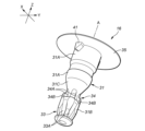
図1及び図3に示されるように、クリップ1は、グロメット15とピン16とを有する。ブラケット4及び複数のグロメット15は、比較的剛性が高い樹脂材料によって形成されているとよい。ブラケット4及び複数のグロメット15は、繊維強化プラスチックによって形成されているとよく、例えばガラス繊維を含むポリブチレンテレフタレートによって形成されているとよい。ピン16は、ブラケット4よりも可撓性が高い樹脂材料によって形成されているとよい。ピン16は、例えば、ポリアセタールによって形成されているとよい。
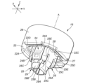
図3、図4、図6、及び図7に示されるように、グロメット15は、受容孔21を有する本体部22と、本体部22における受容孔21の周囲から受容孔21の軸線Aに沿って延びる複数の係止爪24及び複数の支持片25とを有する。軸線Aと平行な方向をZ方向とする。本体部22は円板形に形成され、パネル3と対向する第1面22Aと、第1面22Aと相反する第2面22Bとを有する。受容孔21の軸線Aは、本体部22の軸線Aと一致している。受容孔21は本体部22を第1面22Aから第2面22Bに貫通している。本体部22は、ブラケット4と一体に形成されている。本体部22は、その外周部22Dにおいてブラケット4に接続しているとよい。本体部22の第2面22Bには、軸線Aを中心とした円筒形の周壁26が設けられている。ブラケット4は、周壁26にも接続しているとよい。
本体部22の適所には、複数の肉抜き孔27が形成されている。複数の肉抜き孔27は、第1面22Aから第2面22Bに貫通しているとよい。複数の肉抜き孔27は、軸線Aを中心とした周方向に延び、本体部22を中央部22Cと外周部22Dとに区画している。中央部22Cと外周部22Dとは、隣り合う肉抜き孔27の間に設けられた複数の梁部28によって互いに接続されている。軸線Aに沿った方向から見て、中央部22Cの外形は、正方形に形成されている。
受容孔21は、中央部22Cに形成されている。本実施形態では、受容孔21は正方形の断面形状を有する。なお、受容孔21の断面形状は円形や長方形であってもよい。受容孔21によって、中央部22Cは筒形に形成されている。
本実施形態では、一対の係止爪24と一対の支持片25とが本体部22の第1面22Aに設けられている。一対の係止爪24は、軸線Aと直交するX方向において、軸線Aを挟んで互いに対向している。一対の支持片25は、軸線A及びX方向と直交するY方向において、軸線Aを挟んで互いに対向している。
係止爪24のそれぞれは、本体部22から軸線Aと平行に延びる第1片部24Aと、第1片部24Aの先端から受容孔21と相反する側に突出した爪部24Bとを有する。各第1片部24Aは、X方向と直交する平板状に形成されている。各第1片部24Aの先端は、X方向に弾性変形によって変位することができる。
支持片25のそれぞれは、本体部22から軸線Aと平行に延びる第2片部25Aと、第2片部25Aの先端から受容孔21側に突出した係止凸部25Bとを有する。また、支持片25のそれぞれは、本体部22から軸線Aと平行に延びる一対の柱部25Cと、第2片部25Aと一対の柱部25Cとを接続する一対の接続部25Dとを有するとよい。X方向において、一対の柱部25Cの間に第2片部25Aが一対のスリット25Eを介して配置されている。一対の接続部25Dは、X方向に延びて第2片部25Aと対応する柱部25Cとを接続している。また、接続部25Dは、中央部22Cに接続している。各スリット25Eは、第2片部25Aと、柱部25Cと、接続部25Dとによって画定されている。スリット25Eによって、第2片部25Aと柱部25Cとは、互いに独立して撓むことができる。
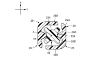
各柱部25Cの先端は、第1片部24Aの先端よりも本体部22から離れている。第2片部25Aの先端は、各柱部25Cの先端よりも本体部22から離れている。各第2片部25Aの先端は、軸線A側に傾斜している。第2片部25Aのそれぞれの先端には、軸線Aを中心とした周方向に延びる保持片29が設けられている。保持片29のそれぞれは、第1片部24Aの先端よりも本体部22から離れた位置に配置されている。また、保持片29のそれぞれは、各柱部25Cの先端よりも前記本体部22から離れた位置に配置されている。
各保持片29は、第2片部25Aの先端からX方向に延びる第1部分29Aと、第1部分29Aの一端からY方向に延びる第2部分29Bとを有する。軸線Aに直交する断面において、一対の保持片29は小径部31Bを囲む枠形を形成するように配置されている。枠形は、四角形に形成されているとよい。保持片29のそれぞれは、対応する第2片部25Aから軸線Aを中心として反時計回りに延びているとよい。なお、周方向(回転方向)は、軸線Aに沿って基端側(本体部22側)から見た状態を基準とする。各保持片29は、第2片部25Aの基端よりも軸部31側に配置されている。
図5に示されるように、ピン16は、受容孔21に挿入される軸部31を有する。受容孔21に挿入された軸部31は、軸線Aと同軸に配置される。軸部31の基端は第2面22Bから突出し、軸部31の先端は第1面22Aから突出している。軸部31は、基端側に設けられた大径部31Aと、大径部31Aより先端側に設けられ、大径部31Aよりも小さな直径を有する小径部31Bとを有する。大径部31Aと小径部31Bとの間には、小径部31Bから大径部31Aに向けて径が漸増するテーパ部31Cが設けられている。小径部31Bは、先端側に設けられた第1係合部33と、第1係合部33よりも大径部31A側に設けられた第2係合部34とを有する。
第1係合部33は、軸部31の周方向に沿って配置された複数の第1凹部33Aを含む。本実施形態では、第1係合部33は、4つの第1凹部33Aを含む。各第1凹部33Aは、軸部31の中心側に凹むと共に基端側に延びている。各第1凹部33Aの深さは、基端側に向けて浅くなっている。
第2係合部34は、軸部31の周方向に沿って配置された複数の第2凹部34Aを含む。本実施形態では、第2係合部34は、4つの第2凹部34Aを含む。各第2凹部34Aは、軸部31の中心側に凹んでいる。第2凹部34Aのそれぞれの底部には、軸部31の周方向に向けて深さが浅くなる傾斜面34Bが設けられている。
軸部31の基端には、円板形のフランジ35が設けられている。フランジ35は、薄く形成され、可撓性を有する。図6及び図9に示されるように、軸部31の内部には内孔37が形成されている。内孔37は、基端の端面から軸線Aに沿って先端側に延びている。内孔37は、大径部31A及びテーパ部31Cを通過して小径部31Bまで到達していてもよい。内孔37の開口部、すなわち軸部31の基端の端面には、工具係合部38が形成されている。工具係合部38は、プラスドライバーやマイナスドライバー等の工具に係合可能に形成されているとよい。
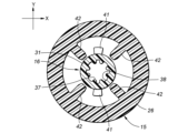
図5に示されるように、軸部31の基端部の外周面には第1カム41が設けられている。本実施形態では、2つの第1カム41が軸線Aを中心として180度間隔で配置されている。各第1カム41は、ピン16の時計回り方向に向けて本体部22側に突出する傾斜面に形成されている。各第1カム41は、軸部31とフランジ35との境界に設けられているとよい。
図6及び図9に示されるように、本体部22には第1カム41に当接する第2カム42が設けられている。本実施形態では、4つの第2カム42が本体部22の第2面22Bに、軸線Aを中心として90度間隔で配置されている。各第2カム42は、第2面22Bから突出すると共に、軸線Aと直交する方向に延びている。
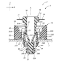
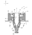
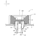
ピン16はグロメット15に対して仮止め位置と締結位置との間で移動可能である。図7に示されるように、ピン16が仮止め位置にあるときに、係止凸部25Bのそれぞれが第1係合部33に係合する。詳細には、ピン16が仮止め位置にあるときに、係止凸部25Bのそれぞれが第1係合部33の第1凹部33Aのいずれかに係合する。図11に示されるように、ピン16が締結位置にあるときに、係止凸部25Bのそれぞれが第2係合部34に係合する。詳細には、ピン16が締結位置にあるときに、係止凸部25Bのそれぞれが第2係合部34の第2凹部34Aのいずれかに係合する。ピン16が仮止め位置にある状態を、クリップ1の仮止め状態という。ピン16が締結位置にある状態を、クリップ1の締結状態という。
以下に、クリップ1の動作及び作用について説明する。作業者は、ブラケット4をパネル3に取り付ける前に各クリップ1を仮止め状態にする。作業者は、ピン16の軸部31を第2面22B側からグロメット15の受容孔21に挿入することによってクリップ1を仮止め状態にすることができる。このとき、軸部31の先端は、各係止凸部25Bに当接し、各第2片部25Aを外方に弾性変形させる。第1係合部33が各係止凸部25Bに到達すると、各係止凸部25Bは対応する第1凹部33Aに突入し、各第2片部25Aは初期状態に復帰する。これにより、クリップ1は初期状態になる。
図6に示されるように、ピン16が仮止め位置にあるときに、第1片部24Aのそれぞれは小径部31Bと隙間を介して対向することによって軸部31側に変位可能になる。また、図7及び図8に示されるように、一対の保持片29は、軸部31の先端を囲むように配置され、軸部31の姿勢を維持する。これにより、軸部31のグロメット15に対する倒れが抑制される。図6に示されるように、フランジ35はグロメット15の周壁26の端面から離れている。また、図9に示されるように、クリップ1が仮止め状態であるとき、各第1カム41は複数の第2カム42から離れている。
図6に示されるように、仮止め状態のクリップ1は、基準孔7A又は副孔7Bである結合孔7に挿入される。このとき、各係止爪24の各爪部24Bが結合孔7の縁部に押され、各第1片部24Aが軸部31側に弾性変形する。これにより、各係止爪24は結合孔7を通過することができる。各爪部24Bが結合孔7を通過すると、各第1片部24Aは初期状態に復元し、各爪部24Bが結合孔7の縁部を係止する。これにより、クリップ1は結合孔7に仮止めされる。クリップ1が結合孔7に仮止めされた状態で、4つの柱部25Cは、結合孔7の4つの隅部に配置される。
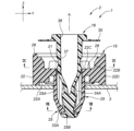
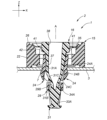
クリップ1が結合孔7に仮止めされた状態において、作業者又は機械によってピン16が締結位置に押し込まれると、図10~図12に示されるようにクリップ1は締結状態になる。このとき、各係止凸部25Bは第1凹部33A内を摺動して、第1凹部33Aに接続した第2凹部34Aに到達する。図11に示されるように各第1凹部33Aは、基端側に向けて深さが浅くなっている。そのため、各係止凸部25Bが対向する第1凹部33A内を摺動するときに、各第2片部25Aは軸部31の径方向外方に弾性変形する。各係止凸部25Bが第2凹部34Aに突入すると、各第2片部25Aは初期状態に復元する。各第1凹部33Aと対応する第2凹部34Aとの境界において、第2凹部34Aは第1凹部33Aよりも深く形成されている。そのため、各係止凸部25Bは第1凹部33Aから第2凹部34Aに摺動することはできるが、第2凹部34Aから第1凹部33Aに摺動することはできない。これにより、ピン16は締結位置に維持される。
図10に示されるようにピン16が締結位置にあるときに、第1片部24Aのそれぞれは大径部31Aと当接することによって軸部31側への変位が規制される。これにより、各爪部24Bが結合孔7を通過できなくなり、クリップ1は結合孔7に結合した状態に維持される。ピン16が締結位置にあるとき、フランジ35はグロメット15の周壁26の端面に密着し、本体部22の第2面22Bを覆う。
作業者は工具を工具係合部38に挿入し、ピン16を反時計回りに回転させることによって、クリップ1を締結状態から仮止め状態に変化させることができる。図13及び図14に示されるように、ピン16が反時計回りに回転することによって、各係止凸部25Bは対応する第2凹部34Aの傾斜面34Bを周方向に摺動し、第2凹部34Aから離脱する。このとき、図15に示されるように、第1カム41と第2カム42とが互いに摺動して軸部31が前記受容孔21から離脱する方向に移動する。これにより、図13に示されるように、各係止凸部25Bが小径部31Bの外面を摺動して、第1凹部33A側に移動する。これにより、クリップ1は仮止め状態になる。クリップ1が仮止め状態であるとき、作業者はクリップ1を結合孔7から引き抜くことができる。このとき、一対の係止爪24は、結合孔7の縁部に押されて軸部31側に弾性変形することによって、結合孔7を通過することができる。
実施形態に係るクリップ1によれば、材料によらず、適切な締結状態を維持することができるクリップ1を提供することができる。ピン16が仮止め位置にあるときに係止爪24は軸部31側に変位することができるため、係止爪24は結合孔7を通過することができる。ピン16が締結位置にあるとき、係止爪24は軸部31側に変位することができないため、係止爪24が結合孔7を係止した状態に維持される。ピン16が締結位置にあるとき、係止爪24は変形していないため、係止爪24の塑性変形が抑制される。これにより、グロメット15に繊維強化樹脂等の剛性が比較的高い材料を使用することができる。また、ピン16が仮止め位置にあるとき、軸部31と係止爪24との間には隙間が形成されているが、複数の支持片25の係止凸部25Bと保持片29とが軸部31の囲むため、軸部31のグロメット15に対する倒れが抑制される。
保持片29は第1片部24Aよりも先端側において軸部31を保持するため、軸部31のグロメット15に対する倒れが一層適切に抑制される。保持片29は軸部31の先端を囲むように配置されているため、軸部31の様々な方向への倒れを規制することができる。また、保持片29が軸線Aを中心とした反時計回りに延びているため、クリップ1を締結状態から解除するときに軸部31が反時計回りに回転しても、保持片29の先端が軸部31に引っ掛かることが抑制される。これにより、ピン16の円滑な回転が可能になる。
軸部31の内部に内孔37が形成されているため、軸部31が弾性変形し易くなる。これにより、作業者が軸部31を仮止め位置から締結位置に押し込み易くなる。
次に、各クリップ1と基準孔7A及び3つの副孔7Bとの関係について説明する。副孔7Bのそれぞれに挿入されるクリップ1の一対の係止爪24は、副孔7Bの一対の第1辺部11に係合する。すなわち、副孔7Bのそれぞれに挿入されるグロメット15の係止爪24の変位方向のそれぞれは、同一方向になっている。すなわち、副孔7Bのそれぞれに挿入されるクリップ1のX方向は同一方向になっている。また、本実施形態では、基準孔7Aに挿入されるクリップ1の一対の係止爪24も、基準孔7Aの第1辺部11に係合する。
副孔7Bのそれぞれに挿入されるクリップ1の一対の支持片25は、副孔7Bの一対の第2辺部12に対向する。すなわち、副孔7Bのそれぞれに挿入されるクリップ1のY方向は同一方向になっている。また、本実施形態では、基準孔7Aに挿入されるクリップ1の一対の支持片25も、基準孔7Aの第2辺部12に対向する。
図16は、基準孔7Aに挿入されるクリップ1の支持片25を示す。図17は副孔7Bに挿入されるクリップ1の支持片25を示す。図16及び図17に示されるように、副孔7Bに挿入されるクリップ1の柱部25Cの先端から接続部25Dまでの距離は、基準孔7Aに挿入されるクリップ1の柱部25Cの先端から接続部25Dまでの距離よりも大きい。すなわち、副孔7Bに挿入されるクリップ1の接続部25Dの軸線Aに沿った方向の幅は、基準孔7Aに挿入されるクリップ1の接続部25Dの軸線Aに沿った方向の幅よりも小さい。また、副孔7Bに挿入されるクリップ1のスリット25Eの長さは、基準孔7Aに挿入されるクリップ1のスリット25Eの長さよりも長い。これにより、副孔7Bに挿入されるクリップ1の柱部25Cは、基準孔7Aに挿入される柱部25Cよりも高い可撓性を有する。
製造誤差により、基準孔7Aと各副孔7Bとの距離に対して、基準孔7Aに挿入されるクリップ1と副孔7Bに挿入されるクリップ1との距離が第2辺部12に沿った方向(上下方向)にずれる場合がある。この場合、図18及び図19に示されるように、副孔7Bに挿入されるクリップ1の係止爪24と柱部25Cが弾性変形して倒れることによって、係止爪24と柱部25Cが副孔7Bに挿入可能になる。このとき、係止爪24及び柱部25Cは副孔7Bの縁部に当接しているため、副孔7Bに対してクリップ1は、がた付きなく結合することができる。このように、各副孔7Bに挿入されるクリップ1の係止爪24は同一方向に変位可能であるため、各クリップ1は各係止爪24の変位方向に製造誤差を許容することできる。各クリップ1の係止爪24は、対応する副孔7Bの縁部に当接するため、締結構造2の安定性が向上する。
図18に示されるように、第1片部24Aの先端の軸部31側の部分には、軸部31と相反する方向に凹む凹部24Cが形成されている。凹部24Cによって第1片部24Aと軸部31との間の隙間が大きくなるため、ピン16が仮止め位置にあるときに第1片部24Aが軸部31側に変位することができる。
内孔37は軸部31の可撓性を高める効果がある。これにより、副孔7Bに挿入された係止爪24が傾斜していても、軸部31の大径部31Aが中央側に変形することによってピン16は仮止め位置から締結位置に移動することができる。
基準孔7Aに挿入されるクリップ1の接続部25Dは、基準孔7Aに突入しているとよい。これにより、柱部25Cの変形が抑制され、基準孔7Aに対してクリップ1が適正な位置に配置される。また、基準孔7Aに挿入されるクリップ1の4つの柱部25Cが基準孔7Aの4つの隅部に配置されるため、基準孔7Aに対してクリップ1が適正な位置に配置される。
副孔7Bの第1辺部11は、クリップ1の第1辺部11に沿った方向の幅よりも大きい。そのため、クリップ1は副孔7B内において第1辺部11に沿った方向に移動することができる。製造誤差により、基準孔7Aと各副孔7Bとの距離に対して、基準孔7Aに挿入されるクリップ1と副孔7Bに挿入されるクリップ1との距離が第1辺部11に沿った方向(左右方向)にずれる場合がある。この場合、クリップ1は副孔7B内において第1辺部11に沿った方向に移動して製造誤差を許容する。
以上で具体的実施形態の説明を終えるが、本発明は上記実施形態に限定されることなく幅広く変形実施することができる。例えば、パネル3の向き、パネル3における基準孔7A及び副孔7Bの位置及び数は任意に変更してよい。また、ブラケット4におけるクリップ1の位置及び数は任意に変更してよい。
1 :クリップ
2 :締結構造
3 :パネル
4 :ブラケット
7 :結合孔
7A :基準孔
7B :副孔
11 :第1辺部
12 :第2辺部
15 :グロメット
16 :ピン
21 :受容孔
22 :本体部
24 :係止爪
24A :第1片部
24B :爪部
24C :凹部
25 :支持片
25A :第2片部
25B :係止凸部
25C :柱部
25D :接続部
25E :スリット
29 :保持片
29A :第1部分
29B :第2部分
31 :軸部
31A :大径部
31B :小径部
33 :第1係合部
33A :第1凹部
34 :第2係合部
34A :第2凹部
34B :傾斜面
41 :第1カム
42 :第2カム
2 :締結構造
3 :パネル
4 :ブラケット
7 :結合孔
7A :基準孔
7B :副孔
11 :第1辺部
12 :第2辺部
15 :グロメット
16 :ピン
21 :受容孔
22 :本体部
24 :係止爪
24A :第1片部
24B :爪部
24C :凹部
25 :支持片
25A :第2片部
25B :係止凸部
25C :柱部
25D :接続部
25E :スリット
29 :保持片
29A :第1部分
29B :第2部分
31 :軸部
31A :大径部
31B :小径部
33 :第1係合部
33A :第1凹部
34 :第2係合部
34A :第2凹部
34B :傾斜面
41 :第1カム
42 :第2カム
Claims (7)
- 結合孔が形成されたパネルに結合するクリップであって、
受容孔を有する本体部と、前記本体部における前記受容孔の周囲から前記受容孔の軸線に沿って延びる複数の係止爪及び複数の支持片とを有するグロメットと、
前記受容孔に挿入される軸部を有するピンとを有し、
前記軸部は、基端側に設けられた大径部と、前記大径部より先端側に設けられ、前記大径部よりも小さな直径を有する小径部とを有し、
前記小径部は、先端側に設けられた第1係合部と、前記第1係合部よりも前記大径部側に設けられた第2係合部とを有し、
前記係止爪のそれぞれは、前記本体部から前記受容孔の前記軸線と平行に延びる第1片部と、前記第1片部の先端から前記受容孔と相反する側に突出した爪部とを有し、
前記支持片のそれぞれは、前記本体部から前記受容孔の前記軸線と平行に延びる第2片部と、前記第2片部の先端から前記受容孔側に突出した係止凸部とを有し、
前記係止凸部のそれぞれが前記第1係合部に係合した仮止め位置と、前記係止凸部のそれぞれが前記第2係合部に係合した締結位置との間で前記ピンは前記グロメットに対して移動可能であり、
前記ピンが前記仮止め位置にあるときに、前記第1片部のそれぞれは前記小径部と隙間を介して対向することによって前記軸部側に変位可能になり、
前記ピンが前記締結位置にあるときに、前記第1片部のそれぞれは前記大径部と当接することによって前記軸部側への変位が規制され、
前記第2片部のそれぞれの先端には、前記軸線を中心とした周方向に延びる保持片が設けられているクリップ。 - 前記保持片のそれぞれは、前記第1片部の先端よりも前記本体部から離れた位置に配置されている請求項1に記載のクリップ。
- 複数の前記支持片は、一対の前記支持片を含み、
前記軸線に直交する断面において、一対の前記保持片は前記小径部を囲む枠形を形成するように配置されている請求項2に記載のクリップ。 - 前記第2片部は、先端側に向けて前記軸部側に傾斜し、
前記保持片は、前記第2片部の基端よりも前記軸部側に配置されている請求項3に記載のクリップ。 - 前記第2係合部は、前記軸部の周方向に沿って配置された複数の凹部を含み、
前記凹部のそれぞれの底部には、前記軸部の周方向に向けて深さが浅くなる傾斜面が設けられている請求項1に記載のクリップ。 - 前記軸部の基端部の外周面には第1カムが設けられ、
前記本体部には前記第1カムに当接する第2カムが設けられ、
前記軸部が、所定の回転方向に回転することによって、前記係止凸部のそれぞれが対応する前記傾斜面上を摺動して前記凹部から離脱すると共に、前記第1カムと前記第2カムとが互いに摺動して前記軸部が前記受容孔から離脱する方向に移動し、
前記保持片のそれぞれは、対応する前記第2片部から前記回転方向に延びている請求項5に記載のクリップ。 - 前記グロメットの前記本体部は、レーダを支持するブラケットに一体に形成され、
前記パネルが車体パネルである請求項1~6のいずれか1つの項に記載のクリップ。
Priority Applications (2)
| Application Number | Priority Date | Filing Date | Title |
|---|---|---|---|
| KR1020257001649A KR20250072946A (ko) | 2023-11-16 | 2024-08-19 | 클립 |
| CN202480060487.4A CN121889589A (zh) | 2023-11-16 | 2024-08-19 | 卡扣 |
Applications Claiming Priority (2)
| Application Number | Priority Date | Filing Date | Title |
|---|---|---|---|
| JP2023195152A JP2025081993A (ja) | 2023-11-16 | 2023-11-16 | クリップ |
| JP2023-195152 | 2023-11-16 |
Publications (1)
| Publication Number | Publication Date |
|---|---|
| WO2025104992A1 true WO2025104992A1 (ja) | 2025-05-22 |
Family
ID=95742902
Family Applications (1)
| Application Number | Title | Priority Date | Filing Date |
|---|---|---|---|
| PCT/JP2024/029302 Pending WO2025104992A1 (ja) | 2023-11-16 | 2024-08-19 | クリップ |
Country Status (4)
| Country | Link |
|---|---|
| JP (1) | JP2025081993A (ja) |
| KR (1) | KR20250072946A (ja) |
| CN (1) | CN121889589A (ja) |
| WO (1) | WO2025104992A1 (ja) |
Citations (3)
| Publication number | Priority date | Publication date | Assignee | Title |
|---|---|---|---|---|
| WO2010119900A1 (ja) * | 2009-04-14 | 2010-10-21 | 株式会社ニフコ | 固定具及び被取付部材の固定構造 |
| WO2011136105A1 (ja) * | 2010-04-27 | 2011-11-03 | 株式会社ニフコ | 部材締結構造及び部材締結用のクリップ |
| JP2016109192A (ja) * | 2014-12-05 | 2016-06-20 | ポップリベット・ファスナー株式会社 | クリップ |
Family Cites Families (1)
| Publication number | Priority date | Publication date | Assignee | Title |
|---|---|---|---|---|
| JP7350695B2 (ja) | 2020-07-08 | 2023-09-26 | 株式会社ニフコ | クリップ構造及びピン部材 |
-
2023
- 2023-11-16 JP JP2023195152A patent/JP2025081993A/ja active Pending
-
2024
- 2024-08-19 CN CN202480060487.4A patent/CN121889589A/zh active Pending
- 2024-08-19 WO PCT/JP2024/029302 patent/WO2025104992A1/ja active Pending
- 2024-08-19 KR KR1020257001649A patent/KR20250072946A/ko active Pending
Patent Citations (3)
| Publication number | Priority date | Publication date | Assignee | Title |
|---|---|---|---|---|
| WO2010119900A1 (ja) * | 2009-04-14 | 2010-10-21 | 株式会社ニフコ | 固定具及び被取付部材の固定構造 |
| WO2011136105A1 (ja) * | 2010-04-27 | 2011-11-03 | 株式会社ニフコ | 部材締結構造及び部材締結用のクリップ |
| JP2016109192A (ja) * | 2014-12-05 | 2016-06-20 | ポップリベット・ファスナー株式会社 | クリップ |
Also Published As
| Publication number | Publication date |
|---|---|
| CN121889589A (zh) | 2026-04-17 |
| KR20250072946A (ko) | 2025-05-26 |
| JP2025081993A (ja) | 2025-05-28 |
Similar Documents
| Publication | Publication Date | Title |
|---|---|---|
| US8914952B2 (en) | Clip | |
| US8555468B2 (en) | Anti-rattle carrier for magnet fastener | |
| KR20040078591A (ko) | 체결구 | |
| US10036410B2 (en) | Article for blind fastening to a support | |
| CN105358003B (zh) | 紧固件构件、紧固件结构和支撑构件 | |
| WO2025104992A1 (ja) | クリップ | |
| WO2013065320A1 (ja) | ファスナ | |
| JP2021185321A (ja) | ブラインド組立体締結具システム | |
| WO2025104993A1 (ja) | 締結構造 | |
| JP3325113B2 (ja) | クリップ | |
| JP2002029266A (ja) | モールディング保持具 | |
| EP1717457B1 (en) | Fastening system | |
| JP2010255731A (ja) | 取付具 | |
| JP7737813B2 (ja) | ブラインド組立体締結具システム | |
| JP2005188623A (ja) | クリップ | |
| JP4511313B2 (ja) | 自動車のキーシリンダ取付構造 | |
| JP4971247B2 (ja) | スタッドボルト用固定クリップ | |
| JP7777423B2 (ja) | 留め具 | |
| CN115667737A (zh) | 球形接头 | |
| WO2025069881A1 (ja) | クリップ保持構造 | |
| US20260085712A1 (en) | Fastening structure | |
| WO2020059680A1 (ja) | 留め具 | |
| JP7820637B2 (ja) | 内装部品 | |
| KR100551176B1 (ko) | 위치 보정용 훼스너 브라켓의 결합구조 | |
| JPH0726624Y2 (ja) | 取付具 |
Legal Events
| Date | Code | Title | Description |
|---|---|---|---|
| 121 | Ep: the epo has been informed by wipo that ep was designated in this application |
Ref document number: 24891036 Country of ref document: EP Kind code of ref document: A1 |