WO2025074846A1 - アンダーカバーの取り付け構造 - Google Patents
アンダーカバーの取り付け構造 Download PDFInfo
- Publication number
- WO2025074846A1 WO2025074846A1 PCT/JP2024/032874 JP2024032874W WO2025074846A1 WO 2025074846 A1 WO2025074846 A1 WO 2025074846A1 JP 2024032874 W JP2024032874 W JP 2024032874W WO 2025074846 A1 WO2025074846 A1 WO 2025074846A1
- Authority
- WO
- WIPO (PCT)
- Prior art keywords
- undercover
- insertion groove
- vehicle body
- length
- mounting structure
- Prior art date
- Legal status (The legal status is an assumption and is not a legal conclusion. Google has not performed a legal analysis and makes no representation as to the accuracy of the status listed.)
- Pending
Links
Images





Classifications
-
- B—PERFORMING OPERATIONS; TRANSPORTING
- B62—LAND VEHICLES FOR TRAVELLING OTHERWISE THAN ON RAILS
- B62D—MOTOR VEHICLES; TRAILERS
- B62D25/00—Superstructure or monocoque structure sub-units; Parts or details thereof not otherwise provided for
- B62D25/20—Floors or bottom sub-units
Definitions
- the present invention relates to an attachment structure for an undercover that covers the underside of a battery pack.
- a battery pack that supplies power to the motor is located under the vehicle body.
- an undercover is provided to cover the underside of the battery pack to protect the battery pack from foreign objects such as pebbles, mud, and dust.
- Known undercover mounting structures include, for example, one in which the undercover is mounted to the underside of the battery pack via multiple fastening members, and one in which both sides of the undercover are engaged with side sills (see Patent Document 1).
- the undercover is made of a thin plate of metal or synthetic resin and is therefore prone to bending.
- the undercover has also become larger, making the undercover more prone to bending. Therefore, the worker must attach the undercover from below the battery pack while supporting the undercover, which has become larger and is significantly warped, which tends to make the work difficult and some kind of improvement is required.
- the present invention has been made in consideration of the above circumstances, and has an object to provide an undercover mounting structure that is advantageous in facilitating the mounting work and improving the work efficiency.
- one embodiment of the present invention is an undercover mounting structure in which an approximately rectangular undercover covering the underside of a battery pack arranged at the bottom of a vehicle body is attached to the bottom of the vehicle body via fasteners, and is characterized in that an insertion groove is provided on the vehicle body into which one of the opposing sides of the undercover is inserted to regulate the vertical displacement of this one side. Furthermore, one embodiment of the present invention is characterized in that an insertion groove is provided on the vehicle body into which the other of the opposing sides of the undercover is inserted, regulating the vertical displacement of the other side.
- one embodiment of the present invention is characterized in that the insertion groove is formed between an upper flange and a lower flange facing each other, and an opening is formed between the tip of the upper flange and the tip of the lower flange through which the edge of the undercover is inserted into the insertion groove, and the tip of the upper flange protrudes further than the tip of the lower flange.
- one embodiment of the present invention is characterized in that the insertion groove has a length along the length direction of the side, the undercover has a length along the length direction of the side and a width perpendicular to this length, and guides are provided at both ends of the length of the insertion groove to abut against both ends of the length direction of the side of the undercover and prevent the undercover from falling in the width direction.
- one embodiment of the present invention is characterized in that the insertion groove is formed between an upper flange and a lower flange facing each other, the space between the upper flange and the lower flange is formed with a dimension larger than the thickness of the undercover, and a protrusion is provided on the edge that abuts against the upper flange and the lower flange when the edge is inserted into the insertion groove, and suppresses movement of the edge in the thickness direction of the undercover and in a direction perpendicular to the thickness direction.
- one embodiment of the present invention is characterized in that the insertion groove has a length along the length direction of the side, the undercover has a length along the length direction of the side and a width perpendicular to the length, a vehicle body side temporary fastening portion is provided on the lower part of the vehicle body at a location opposite the center of the undercover in the length and width directions, and a cover side temporary fastening portion is provided at the center of the undercover in the length and width directions, which is releasably connected to the vehicle body side temporary fastening portion to temporarily fasten the undercover.
- an insertion groove is provided on the vehicle body into which one of the opposing sides of the undercover is inserted and which restricts the vertical displacement of the one side, so that when attaching the undercover, one side of the undercover is inserted into the insertion groove, which allows one person to easily attach a large undercover, which is advantageous in terms of improving the efficiency of the undercover attachment work. Also, because the side of the undercover can be supported by the insertion groove, the number of fasteners for attaching the undercover to the vehicle body can be reduced, which is advantageous in terms of reducing parts costs.
- the installation work of a larger undercover can be easily performed by one person, which is more advantageous in terms of improving the efficiency of the undercover installation work.
- an opening through which the edge of the undercover is inserted into the insertion groove is provided between the tip of the upper flange and the tip of the lower flange.
- the tip of the upper flange protrudes further than the tip of the lower flange, the tip of the upper flange can be used as a guide during insertion, and the edge of the undercover can be easily inserted into the insertion groove from the opening, which is more advantageous in terms of making the undercover installation work more efficient.
- the guides ensure the strength of the insertion groove, which is advantageous in terms of protecting the insertion groove against the weight of the battery pack.
- the vibration of the undercover while the vehicle is traveling can be suppressed, it is advantageous in terms of ensuring quietness and livability in the vehicle interior and improving the comfort of the occupants.
- a vehicle body side temporary fastening portion is provided on the lower part of the vehicle body at a location facing the center of the undercover in the length and width directions, and a cover side temporary fastening portion is provided at the center of the undercover in the length and width directions that can be engaged and releasably connected to the vehicle body side temporary fastening portion to temporarily fasten the undercover, the undercover installation work can be facilitated without the need for any dedicated jig for temporary fastening, which is advantageous in terms of making the undercover installation work more efficient.
- FIG. 1 is a cross-sectional view of an undercover mounting structure according to a first embodiment, taken along a cross section perpendicular to a vehicle front-rear direction.
- FIG. 2 is a bottom view of the undercover mounting structure according to the first embodiment, as viewed from below.
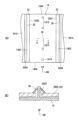
- FIG. 3A is a bottom view of an undercover mounting structure according to a second embodiment, as viewed from below, and
- FIG. 3B is a cross-sectional view taken along line AA of FIG. 3A.
- FIG. 13 is a perspective view of an undercover according to a third embodiment.
- Figures 5 (A) and (B) are cross-sectional views showing the state in which the long side of the undercover is inserted into the insertion groove in the undercover mounting structure of the third embodiment, where Fig.
- FIG. 13 is a bottom view of the undercover mounting structure according to the fourth embodiment, as viewed from below.
- FIG. 13 is a cross-sectional view showing a modified example of the fourth embodiment.
- the undercover mounting structure of this embodiment is applied to a battery pack that is mounted on an electric vehicle that uses a motor as its power source, such as an electric vehicle that uses only a motor as its power source, a hybrid vehicle, or an electric vehicle that uses a motor as its power source, such as a plug-in hybrid vehicle that can be externally charged or powered, and that supplies power to the motor.
- a motor as its power source
- an electric vehicle that uses only a motor as its power source such as an electric vehicle that uses only a motor as its power source, a hybrid vehicle, or an electric vehicle that uses a motor as its power source, such as a plug-in hybrid vehicle that can be externally charged or powered, and that supplies power to the motor.
- a pair of long sides of the bottom wall 2002 of the battery tray 20 are arranged along the front-rear direction of the vehicle, and a pair of short sides of the bottom wall 2002 are arranged along the vehicle width direction.
- the battery cover 22 comprises a rectangular top wall 2202 in a plan view facing the bottom wall 2002, four side walls 2204 vertically extending from the four sides of the top wall 2202, and a rectangular frame-shaped flange 2206 provided on the outer periphery of the lower end of the side walls 2204.
- the battery cover 22 and the battery tray 20 are fastened together by a plurality of bolts B1 with the flange 2206 of the battery cover 22 overlapping the upper end of the side wall 2004 of the battery tray 20.
- the battery tray 20 is disposed at the center in the vehicle width direction, and is attached to a pair of side members 24 via mounting portions 2010 and bolts B2 provided on a pair of side walls 2004 opposing each other in the vehicle width direction.
- reference numeral 26 denotes a floor panel extending in the vehicle longitudinal direction and in the vehicle width direction, and the upper ends of a pair of side members 24 are joined to the lower surface of the floor panel 26 on both sides in the vehicle width direction.
- the lower portions of a pair of side walls 2004 of the battery cover 22 opposing each other in the vehicle width direction are formed with insertion grooves 28 facing each other, into which opposing sides of the undercover 14 are inserted.
- the insertion groove 28 is formed between an upper flange 30 and a lower flange 32 that face each other. Between the tip 3002 of the upper flange 30 and the tip 3202 of the lower flange 32 is an opening 28A through which the edge of the undercover 14 is inserted into the insertion groove 28, and the tip 3002 of the upper flange 30 protrudes further than the tip 3202 of the lower flange 32.
- the insertion groove 28 is formed so as to restrict the vertical displacement of the edge of the undercover 14 when the edge is inserted therein. In FIG.
- the undercover 14 has a rectangular shape, and when the undercover 14 is attached to the lower part of the vehicle body 10, a pair of long sides 1402 of the undercover 14 are arranged along the fore-and-aft direction of the vehicle, and a pair of short sides 1404 of the undercover 14 are arranged along the vehicle width direction. Therefore, the undercover 14 has a length extending in the front-rear direction of the vehicle and a width extending in the vehicle width direction, and in this embodiment, the long side 1402 of the undercover 14 is inserted into the insertion groove 28. Due to the increase in size of the battery pack 12, the length of the undercover 14 is, for example, about 3 m, and the width is about 2 m.
- a plurality of mounting holes 1410 are provided at the center in the width direction of the undercover 14 and spaced apart in the length direction of the undercover 14 .
- a plurality of stud bolts 34 are provided in the bottom wall 2002 of the battery tray 20 , which is the underside of the vehicle body 10 , in correspondence with the plurality of mounting holes 1410 .
- the attachment of the undercover 14 will be described.
- the worker lifts the center of the length of the undercover 14 from below and inserts one long side 1402 of the undercover 14 into one insertion groove 28, and then inserts the other long side 1402 into the other insertion groove 28.
- the longitudinal center of the downwardly bent undercover 14 is pressed against the underside of the bottom wall 2002 of the battery tray 20, the stud bolts 34 are inserted into the mounting holes 1410, and the nuts 36 are tightened onto the stud bolts 34, thereby completing the installation work of the undercover 14.
- the work of attaching the large undercover 14 can be easily performed by one person, and the efficiency of the work of attaching the undercover 14 can be improved.
- the long side 1402 of the undercover 14 can be supported by the insertion groove 28, the number of stud bolts 34 and nuts 36, which are fasteners for attaching the undercover 14 to the battery tray 20 of the battery pack 12, can be reduced, which is advantageous in reducing parts costs.
- an opening 28A through which the side of the undercover 14 is inserted into the insertion groove 28 is formed between the tip 3002 of the upper flange 30 and the tip 3202 of the lower flange 32, and since the tip 3002 of the upper flange 30 protrudes further than the tip 3202 of the lower flange 32, the tip 3002 of the upper flange 30 can be used as a guide during insertion. Therefore, the long side 1402 of the undercover 14 can be easily inserted into the insertion groove 28 from the opening 28A, which is more advantageous in terms of improving the efficiency of the installation work of the undercover 14.
- a vehicle body side temporary fastening portion is provided in place of the stud bolt 34 at a location on the bottom wall 2002 of the battery tray 20, which is the lower part of the vehicle body 10, facing the center of the undercover 14 in the longitudinal and width directions, and the vehicle body side temporary fastening portion is formed by a temporary fastening hole 2020.
- the longitudinal center of the downwardly bent undercover 14 is pressed against the underside of the bottom wall 2002 of the battery tray 20, thereby engaging the temporary fixing pins 38 with the temporary fixing holes 2020 to temporarily fix the undercover 14 to the battery tray 20. Therefore, with the undercover 14 temporarily fixed, the stud bolt 34 can be inserted through the mounting hole 1410 and the nut 36 can be fastened to the stud bolt 34 . Therefore, the installation work of the undercover 14 can be facilitated without the need for any dedicated jig for temporary fixation, which is advantageous in terms of improving the efficiency of the installation work of the undercover 14. In addition, it is optional to form the vehicle body side temporary fastening portion with a temporary fastening pin and the cover side temporary fastening portion with a temporary fastening hole.
- the space between the upper flange 30 and the lower flange 32 that define the insertion groove 28 is formed to have a dimension larger than the thickness of the undercover 14 .
- a protrusion 40 is provided on the long side 1402 of the undercover 14, which abuts against the upper flange 30 and the lower flange 32 when the long side 1402 is inserted into the insertion groove 28, and suppresses movement of the long side 1402 in the thickness direction of the undercover 14 and in a direction perpendicular to the thickness direction.
- the protrusions 40 are provided at a plurality of locations spaced apart in the longitudinal direction of the undercover 14 .
- FIG. 4A shows a case in which the protrusion 40 is formed of a curved portion that protrudes to one side in the thickness direction of the undercover 14 and extends in the length direction of the undercover 14 .
- FIG. 4B shows a case in which the projection 40 is formed as a bulging portion that protrudes to one side in the thickness direction of the undercover 14 .
- the protrusion 40 abuts against the upper flange 30 and the lower flange 32, suppressing movement of the long side 1402 of the undercover 14 in the thickness direction and in the direction perpendicular to the thickness direction.
- the undercover 14 when the undercover 14 is inserted into the insertion groove 28, the undercover 14 is more securely supported via the insertion groove 28 and the protrusion 40.
- This makes it easier for one person to install the enlarged undercover 14, which is more advantageous in terms of improving the efficiency of the installation work of the undercover 14.
- the protrusions 40 suppress movement of the undercover 14 in the thickness direction and in the direction perpendicular to the thickness direction, vibration of the undercover 14 while the vehicle is traveling can be suppressed, which is advantageous in ensuring quietness and livability in the passenger compartment and improving comfort for occupants.
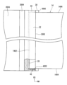
- guides 42 are provided at both ends of the insertion groove 28 in the longitudinal direction, which abut against both ends of the long side 1402 of the undercover 14 in the longitudinal direction to prevent the undercover 14 from falling in the width direction, and an inclined surface 4202 is formed at the tip of the guide 42 to smoothly guide the undercover 14 into the insertion groove 28.
- the guides 42 when inserting the long side 1402 of the undercover 14 into the insertion groove 28, the guides 42 abut against both longitudinal ends of the long side 1402 of the undercover 14, thereby enabling the longitudinal positioning of the long side 1402 of the undercover 14 to be performed.
- the stud bolts 34 can be easily inserted into the mounting holes 1410 of the undercover 14, which facilitates the installation of the undercover 14 and is advantageous in terms of making the installation of the undercover 14 more efficient.
- the weight of the battery pack 12 is applied to the lower flange 32, which constitutes the insertion groove 28.
- the strength of the lower flange 32 is ensured by the guide 42 , which is advantageous in terms of protecting the lower flange 32 against the load of the battery pack 12 . In this case, as shown in FIG.
- a protruding portion 44 may be provided that protrudes downward from the lower surface of the lower flange 32. Providing the protrusion 44 separates the lower surface of the lower flange 32 upward from the floor surface, which is more advantageous in terms of protecting the lower flange 32 against the weight of the battery pack 12.
- the location of the vehicle body 10 where the insertion groove 28 is provided is the lower part of the side wall 2004 of the battery tray 20, but the location of the vehicle body 10 where the insertion groove 28 is provided may include skeletal members such as the side members 24, and members and parts attached to these skeletal members, and therefore is not limited to the battery tray 20 of the battery pack 12 as in the embodiment.
- the location of the vehicle body 10 where the insertion groove 28 is provided is the bottom wall 2002 of the battery tray 20, the upper flange 30 is also used by the bottom wall 2002, so that the upper flange 30 may be omitted and only the lower flange 32 may be provided.
- insertion grooves 28 are provided into which a pair of opposing long sides 1402 of the undercover 14 are inserted, but it is also possible to have a single insertion groove 28 and insert one of the pair of long sides 1402 into this insertion groove 28.
- the installation work of the enlarged undercover 14 can be easily performed by one person, which is more advantageous in terms of improving the efficiency of the installation work of the undercover 14.
Landscapes
- Engineering & Computer Science (AREA)
- Chemical & Material Sciences (AREA)
- Combustion & Propulsion (AREA)
- Transportation (AREA)
- Mechanical Engineering (AREA)
- Body Structure For Vehicles (AREA)
Priority Applications (1)
| Application Number | Priority Date | Filing Date | Title |
|---|---|---|---|
| JP2025550835A JPWO2025074846A1 (https=) | 2023-10-05 | 2024-09-13 |
Applications Claiming Priority (2)
| Application Number | Priority Date | Filing Date | Title |
|---|---|---|---|
| JP2023-173433 | 2023-10-05 | ||
| JP2023173433 | 2023-10-05 |
Publications (1)
| Publication Number | Publication Date |
|---|---|
| WO2025074846A1 true WO2025074846A1 (ja) | 2025-04-10 |
Family
ID=95283109
Family Applications (1)
| Application Number | Title | Priority Date | Filing Date |
|---|---|---|---|
| PCT/JP2024/032874 Pending WO2025074846A1 (ja) | 2023-10-05 | 2024-09-13 | アンダーカバーの取り付け構造 |
Country Status (2)
| Country | Link |
|---|---|
| JP (1) | JPWO2025074846A1 (https=) |
| WO (1) | WO2025074846A1 (https=) |
Citations (5)
| Publication number | Priority date | Publication date | Assignee | Title |
|---|---|---|---|---|
| JPS4725761U (https=) * | 1971-04-14 | 1972-11-22 | ||
| JPH11348833A (ja) * | 1998-06-09 | 1999-12-21 | Fuji Heavy Ind Ltd | 車両用アンダーカバーの取付構造 |
| JP2013256265A (ja) * | 2012-06-14 | 2013-12-26 | Toyota Motor Corp | 車両用電池搭載構造 |
| JP2015164763A (ja) * | 2014-02-28 | 2015-09-17 | キョーラク株式会社 | サンドイッチパネルおよびサンドイッチパネルの製造方法 |
| JP2019189027A (ja) * | 2018-04-25 | 2019-10-31 | トヨタ自動車株式会社 | 車両下部構造 |
-
2024
- 2024-09-13 WO PCT/JP2024/032874 patent/WO2025074846A1/ja active Pending
- 2024-09-13 JP JP2025550835A patent/JPWO2025074846A1/ja active Pending
Patent Citations (5)
| Publication number | Priority date | Publication date | Assignee | Title |
|---|---|---|---|---|
| JPS4725761U (https=) * | 1971-04-14 | 1972-11-22 | ||
| JPH11348833A (ja) * | 1998-06-09 | 1999-12-21 | Fuji Heavy Ind Ltd | 車両用アンダーカバーの取付構造 |
| JP2013256265A (ja) * | 2012-06-14 | 2013-12-26 | Toyota Motor Corp | 車両用電池搭載構造 |
| JP2015164763A (ja) * | 2014-02-28 | 2015-09-17 | キョーラク株式会社 | サンドイッチパネルおよびサンドイッチパネルの製造方法 |
| JP2019189027A (ja) * | 2018-04-25 | 2019-10-31 | トヨタ自動車株式会社 | 車両下部構造 |
Also Published As
| Publication number | Publication date |
|---|---|
| JPWO2025074846A1 (https=) | 2025-04-10 |
Similar Documents
| Publication | Publication Date | Title |
|---|---|---|
| US10069123B2 (en) | Battery pack securing method | |
| US10464406B2 (en) | Vehicle body bottom structure | |
| US10166852B2 (en) | Vehicle body lower structure | |
| US7021412B2 (en) | Structure for mounting box for containing high-voltage electrical equipment on vehicle | |
| JP5012862B2 (ja) | 電気自動車のモータルーム構造 | |
| CN114537118A (zh) | 电池组搭载车辆 | |
| EP2479818B1 (en) | Vehicle battery case. | |
| US8622161B2 (en) | Installation structure for electrical equipment in rear vehicle body | |
| EP2684721A2 (en) | Onboard equipment fixing structure | |
| US20240336149A1 (en) | Body-in-white (biw) integrated battery frame | |
| JP2015081042A (ja) | 電気車両 | |
| JP6122807B2 (ja) | 自動車のバッテリー搭載構造 | |
| CN203580593U (zh) | 一种蓄电池安装结构 | |
| US12308456B2 (en) | Corner shield for electric vehicle battery box | |
| US20200127254A1 (en) | Power storage unit and power storage device | |
| JP2007106244A (ja) | 電気部品の取り付け構造 | |
| JP7243935B1 (ja) | シート及びバッテリの固定構造 | |
| WO2025074846A1 (ja) | アンダーカバーの取り付け構造 | |
| JP2002205556A (ja) | 車両のバッテリ固定構造 | |
| US20230382325A1 (en) | Vehicle | |
| CN209719721U (zh) | 车辆下部结构 | |
| US20260084556A1 (en) | Charger installation structure for vehicle | |
| JP7589594B2 (ja) | 車両構造 | |
| JP7831706B2 (ja) | 電池パックのトレイ及びこのトレイを備える電池パック | |
| US20260084509A1 (en) | Vehicle lower structure |
Legal Events
| Date | Code | Title | Description |
|---|---|---|---|
| 121 | Ep: the epo has been informed by wipo that ep was designated in this application |
Ref document number: 24873875 Country of ref document: EP Kind code of ref document: A1 |
|
| ENP | Entry into the national phase |
Ref document number: 2025550835 Country of ref document: JP Kind code of ref document: A |
|
| WWE | Wipo information: entry into national phase |
Ref document number: 2025550835 Country of ref document: JP |