WO2025069596A1 - 油圧シリンダ装置用作動油および油圧シリンダ装置 - Google Patents
油圧シリンダ装置用作動油および油圧シリンダ装置 Download PDFInfo
- Publication number
- WO2025069596A1 WO2025069596A1 PCT/JP2024/021828 JP2024021828W WO2025069596A1 WO 2025069596 A1 WO2025069596 A1 WO 2025069596A1 JP 2024021828 W JP2024021828 W JP 2024021828W WO 2025069596 A1 WO2025069596 A1 WO 2025069596A1
- Authority
- WO
- WIPO (PCT)
- Prior art keywords
- hydraulic
- hydraulic cylinder
- oil
- cylinder device
- hydraulic oil
- Prior art date
- Legal status (The legal status is an assumption and is not a legal conclusion. Google has not performed a legal analysis and makes no representation as to the accuracy of the status listed.)
- Ceased
Links
Images
Classifications
-
- C—CHEMISTRY; METALLURGY
- C10—PETROLEUM, GAS OR COKE INDUSTRIES; TECHNICAL GASES CONTAINING CARBON MONOXIDE; FUELS; LUBRICANTS; PEAT
- C10M—LUBRICATING COMPOSITIONS; USE OF CHEMICAL SUBSTANCES EITHER ALONE OR AS LUBRICATING INGREDIENTS IN A LUBRICATING COMPOSITION
- C10M171/00—Lubricating compositions characterised by purely physical criteria, e.g. containing as base-material, thickener or additive, ingredients which are characterised exclusively by their numerically specified physical properties, i.e. containing ingredients which are physically well-defined but for which the chemical nature is either unspecified or only very vaguely indicated
-
- F—MECHANICAL ENGINEERING; LIGHTING; HEATING; WEAPONS; BLASTING
- F16—ENGINEERING ELEMENTS AND UNITS; GENERAL MEASURES FOR PRODUCING AND MAINTAINING EFFECTIVE FUNCTIONING OF MACHINES OR INSTALLATIONS; THERMAL INSULATION IN GENERAL
- F16F—SPRINGS; SHOCK-ABSORBERS; MEANS FOR DAMPING VIBRATION
- F16F9/00—Springs, vibration-dampers, shock-absorbers, or similarly-constructed movement-dampers using a fluid or the equivalent as damping medium
- F16F9/32—Details
- F16F9/36—Special sealings, including sealings or guides for piston-rods
-
- C—CHEMISTRY; METALLURGY
- C10—PETROLEUM, GAS OR COKE INDUSTRIES; TECHNICAL GASES CONTAINING CARBON MONOXIDE; FUELS; LUBRICANTS; PEAT
- C10M—LUBRICATING COMPOSITIONS; USE OF CHEMICAL SUBSTANCES EITHER ALONE OR AS LUBRICATING INGREDIENTS IN A LUBRICATING COMPOSITION
- C10M137/00—Lubricating compositions characterised by the additive being an organic non-macromolecular compound containing phosphorus
- C10M137/02—Lubricating compositions characterised by the additive being an organic non-macromolecular compound containing phosphorus having no phosphorus-to-carbon bond
- C10M137/04—Phosphate esters
- C10M137/10—Thio derivatives
-
- C—CHEMISTRY; METALLURGY
- C10—PETROLEUM, GAS OR COKE INDUSTRIES; TECHNICAL GASES CONTAINING CARBON MONOXIDE; FUELS; LUBRICANTS; PEAT
- C10M—LUBRICATING COMPOSITIONS; USE OF CHEMICAL SUBSTANCES EITHER ALONE OR AS LUBRICATING INGREDIENTS IN A LUBRICATING COMPOSITION
- C10M155/00—Lubricating compositions characterised by the additive being a macromolecular compound containing atoms of elements not provided for in groups C10M143/00 - C10M153/00
-
- C—CHEMISTRY; METALLURGY
- C10—PETROLEUM, GAS OR COKE INDUSTRIES; TECHNICAL GASES CONTAINING CARBON MONOXIDE; FUELS; LUBRICANTS; PEAT
- C10N—INDEXING SCHEME ASSOCIATED WITH SUBCLASS C10M RELATING TO LUBRICATING COMPOSITIONS
- C10N2010/00—Metal present as such or in compounds
- C10N2010/04—Groups 2 or 12
-
- C—CHEMISTRY; METALLURGY
- C10—PETROLEUM, GAS OR COKE INDUSTRIES; TECHNICAL GASES CONTAINING CARBON MONOXIDE; FUELS; LUBRICANTS; PEAT
- C10N—INDEXING SCHEME ASSOCIATED WITH SUBCLASS C10M RELATING TO LUBRICATING COMPOSITIONS
- C10N2030/00—Specified physical or chemical properties which is improved by the additive characterising the lubricating composition, e.g. multifunctional additives
- C10N2030/06—Oiliness; Film-strength; Anti-wear; Resistance to extreme pressure
-
- C—CHEMISTRY; METALLURGY
- C10—PETROLEUM, GAS OR COKE INDUSTRIES; TECHNICAL GASES CONTAINING CARBON MONOXIDE; FUELS; LUBRICANTS; PEAT
- C10N—INDEXING SCHEME ASSOCIATED WITH SUBCLASS C10M RELATING TO LUBRICATING COMPOSITIONS
- C10N2040/00—Specified use or application for which the lubricating composition is intended
- C10N2040/06—Instruments or other precision apparatus, e.g. damping fluids
Definitions
- the present invention relates to hydraulic oil for hydraulic cylinder devices and hydraulic cylinder devices that use the hydraulic oil.
- a hydraulic cylinder device is a device that contains a piston, a piston rod fixed to the piston, and hydraulic oil in a cylinder tube, and causes the piston and piston rod to move back and forth by pumping hydraulic oil in and out, and damps the reciprocating motion of the piston rod with the flow resistance of the hydraulic oil.
- a piston seal also called a piston packing or piston band
- a rod seal also called a rod packing or oil seal
- the piston seal slides against the cylinder tube
- the piston rod reciprocates while sliding against the rod seal.
- Phosphate esters added to hydraulic oil are catalytically active on the surfaces of the cylinder tube and piston rod, releasing protons.
- the release of protons triggers the stable formation of an adsorption film on the surfaces of the cylinder tube and piston rod.
- the wear-resistant effect of this adsorption film reduces wear in the sliding areas.
- phosphate esters refer to orthophosphate compounds or phosphite compounds.
- orthophosphate compounds include tricresyl phosphate, triphenyl phosphate and its derivatives, trixylenyl phosphate, cresyl diphenyl phosphate, 2-ethylhexyl diphenyl phosphate, and tris(2-ethylhexyl) phosphate.
- phosphite compounds include lauryl acid phosphate, oleyl acid phosphate, dilauryl hydrogen phosphite, distearyl hydrogen phosphite, and dioleyl hydrogen phosphite.
- hydraulic oils containing orthophosphate compounds or phosphite compounds have the negative effect of swelling the synthetic rubber (e.g., NBR) of the rod seal and softening the surface hardness.
- the amount of phosphate esters added is suppressed to 0.1 parts by mass or less per 100 parts by mass of base oil. It is more preferable that the amount of phosphate esters added is 0.01 parts by mass or less, and it is even more preferable that they are not intentionally added.
- the base oil used in the present invention may be a mineral oil and/or a synthetic oil that has been conventionally used as a base oil for hydraulic cylinders.
- the base oil may be a single mineral oil or a synthetic oil, or a combination of multiple mineral oils and synthetic oils.
- mineral oils include paraffin-based mineral oils and naphthenic mineral oils.
- synthetic oils include polybutene-based synthetic oils, polypropylene-based synthetic oils, poly- ⁇ -olefin-based synthetic oils, ester-based synthetic oils, polyalkylene glycol-based synthetic oils, polyphenyl ether-based synthetic oils, polyglycol-based synthetic oils, polyphenyl ether-based synthetic oils, alkylbenzene-based synthetic oils, synthetic naphthenic synthetic oils, and ionic liquids.
- the aniline point means the lowest temperature at which the same volume of aniline and the measurement sample exist as a homogeneous solution, and is one of the indices for estimating the swelling property of the sealing material with which it comes into contact.
- the aniline point of the hydraulic oil is preferably in the range of 85°C to 110°C. If the aniline point of the hydraulic oil is less than 85°C, the sealing material will swell and soften more than necessary, making it more susceptible to scratches due to sliding (reduced scratch resistance). On the other hand, if the aniline point of the hydraulic oil exceeds 110°C, the sealing material will shrink and harden more than necessary, making it easier for the sealing property of the hydraulic oil to decrease.
- the aniline point of the hydraulic oil is more preferably in the range of 85°C to 105°C, and even more preferably in the range of 90°C to 105°C.
- the surface hardness of the sealing material before contact with hydraulic oil e.g. durometer hardness/Shore A hardness
- softening/hardening due to contact with hydraulic oil within a variation of ⁇ 10% is considered to be within the acceptable range from the perspective of the scratch resistance/adhesion of the sealing material. It is more preferable to limit the variation in the surface hardness of the sealing material due to contact with hydraulic oil to softening/hardening within a range of ⁇ 5%.
- the aniline point of the hydraulic oil within the range of 85°C to 110°C, the variation in the surface hardness of the sealing material due to contact with the hydraulic oil can be suppressed to within ⁇ 10%, resulting in a balance between the scratch resistance of the sealing material and the sealing ability of the hydraulic oil.
- Zinc dialkyldithiophosphate is an additive in the present invention that contributes to wear resistance and oxidation resistance.
- the alkyl group of zinc dialkyldithiophosphate can be a primary alkyl group, a secondary alkyl group, or a tertiary alkyl group, with a primary alkyl group or a secondary alkyl group being preferred.
- the number of carbon atoms in the alkyl group is preferably 1 to 24, and more preferably 4 to 12.
- the amount of zinc dialkyldithiophosphate added is preferably 0.1 to 3 parts by mass per 100 parts by mass of base oil in order to achieve both oxidation resistance and wear resistance. If the amount added is less than 0.1 parts by mass, the positive effects (oxidation resistance and wear resistance) will not be fully obtained, and if it exceeds 3 parts by mass, it will be difficult to dissolve in the base oil, which may cause sludge to form.
- the boron-containing alkenyl succinimide is an additive that contributes to wear resistance and sludge dispersibility in the present invention, and examples thereof include boron-containing polybutenyl succinimide and boron-containing polybutenyl benzylamine. They may be used alone or in combination of multiple types.
- the amount of boron-containing alkenyl succinimide added is preferably 0.1 to 3 parts by mass per 100 parts by mass of base oil in order to achieve both wear resistance and sludge dispersibility. If the amount added is less than 0.1 parts by mass, the positive effects (wear resistance and sludge dispersibility) will not be fully obtained, and if it exceeds 3 parts by mass, it will be difficult to dissolve in the base oil, which may cause sludge to form.
- the hydraulic oil of the present invention may further contain one or more additives selected from the group consisting of an oiliness improver, an antioxidant, an ashless dispersant, a metal-based detergent dispersant, a viscosity index improver, a pour point depressant, a metal deactivator, a rust inhibitor, and an antifoaming agent, depending on the application of the hydraulic cylinder device.
- additives it is preferable to contain one or more additives selected from the group consisting of an antioxidant, a metal-based detergent dispersant, a viscosity index improver, a rust inhibitor, and an antifoaming agent.
- the total amount of additives added is preferably 0.2 parts by mass or more and 20 parts by mass or less per 100 parts by mass of base oil, and more preferably 5 parts by mass or more and 10 parts by mass or less.
- oiliness improvers for example, fatty alcohols and their derivatives, fatty acid esters and their derivatives, fatty acids and their derivatives, amine compounds and their derivatives, amide compounds and their derivatives, etc. can be suitably used.
- antioxidants for example, amine-based antioxidants and their derivatives, phenol-based antioxidants and their derivatives, sulfur-based antioxidants and their derivatives, carbamate-based antioxidants and their derivatives, etc. can be suitably used.
- ashless dispersants examples include succinimide and its derivatives, benzylamine and its derivatives, and esters and their derivatives.
- suitable metal-based detergent dispersants include calcium salicylate and its derivatives, calcium phenate and its derivatives, calcium sulfonate and its derivatives, and potassium borate and its derivatives.
- polymethacrylate and its derivatives polyisobutylene and its derivatives, olefin copolymers and its derivatives, etc. can be suitably used as viscosity index improvers.
- pour point depressants for example, polymethacrylate and its derivatives, polybutene and its derivatives, polyalkylstyrene and its derivatives, etc. can be suitably used.
- metal deactivators examples include benzotriazole and its derivatives, and thiadiazole and its derivatives.
- rust inhibitors for example, imidazole and its derivatives, benzotriazole and its derivatives, thiadiazole and its derivatives, etc. can be suitably used.
- antifoaming agents for example, silicone-based antifoaming agents and their derivatives, polyacrylate-based antifoaming agents and their derivatives, etc. can be suitably used.
- the preferred kinetic viscosity of the hydraulic oil varies depending on the application of the hydraulic cylinder device.
- the kinetic viscosity at 40°C is preferably 8 mm 2 /s or more and 17 mm 2 /s or less from the viewpoint of low-temperature fluidity.
- hydraulic cylinder device Next, an embodiment of the hydraulic cylinder device according to the present invention will be described.
- a hydraulic shock absorber for an automobile will be taken as an example.
- the hydraulic cylinder device according to the present invention is not limited to the hydraulic shock absorber for an automobile.
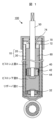
- FIG. 1 is a schematic cross-sectional view of an automobile hydraulic shock absorber, which is an example of a hydraulic cylinder device according to the present invention.
- the automobile hydraulic shock absorber 100 shown in Figure 1 is a twin-cylinder hydraulic shock absorber with a retractable rod, and the cylinder section 10 has a double structure of an outer cylinder 20 and an inner cylinder 30 (also called a cylinder tube).
- a piston 40 is disposed inside the inner cylinder 30, and one end of a piston rod 50 is fixed to the piston 40 and the other end is disposed so as to protrude from the cylinder section 10 (outer cylinder 20, inner cylinder 30), and hydraulic oil 60 is sealed in such a way that it fills the inner cylinder 30.
- a rod guide 70 and a guide bush 72 are provided on the side of the cylindrical portion 10 from which the piston rod 50 protrudes, which suppresses the radial movement of the piston rod 50, and a rod seal 74 is provided to prevent unwanted external leakage of the hydraulic oil 60.
- the piston 40 is provided with a piston valve 42 that uses the flow resistance of the hydraulic oil 60 to generate a damping force, and a piston seal 44 to prevent undesired loss of pressure in the hydraulic oil 60.
- the hydraulic oil 60 passes through the piston valve 42 provided on the piston 40 and flows in and out of the upper piston chamber A and the lower piston chamber B in the inner cylinder 30, and passes through the base valve 32 provided at the bottom of the inner cylinder 30 and flows in and out of the reservoir chamber C between the inner cylinder 30 and the outer cylinder 20.
- a telescopic rod, twin-tube hydraulic shock absorber generates a damping force by utilizing the flow resistance when the hydraulic oil 60 passes through the piston valve 42 and the base valve 32.
- the damping force in the compression direction is generally controlled by the base valve 32
- the damping force in the extension direction is generally controlled by the piston valve 42.
- the automobile hydraulic shock absorber 100 has three main sliding parts (inner cylinder 30/piston seal 44, piston rod 50/guide bush 72, piston rod 50/rod seal 74). It is important to ensure wear resistance at each sliding part, but if the rod seal 74 is damaged at the piston rod 50/rod seal 74 sliding part, the hydraulic oil 60 is likely to leak to the outside from the damaged part.
- the material for the guide bush 72, rod seal 74, and piston seal 44 is preferably acrylonitrile-butadiene rubber (NBR) with a Shore A hardness of 75 to 90 at 20°C and an acrylonitrile content of 30% by mass or less. NBR with an acrylonitrile content of 24% by mass or less is more preferable.
- NBR acrylonitrile-butadiene rubber
- the surface of the piston rod 50 is chrome plated for rust prevention and wear resistance.
- the chrome plating layer preferably has a surface roughness (arithmetic mean roughness Ra) of 0.1 ⁇ m or less. If the chrome plating layer has a Ra of more than 0.1 ⁇ m, friction will increase at the sliding parts of the piston rod 50/guide bush 72 and the piston rod 50/rod seal 74, causing a decrease in the smoothness of the reciprocating motion.
- the average thickness of the chrome plating layer is preferably in the range of 10 ⁇ m to 30 ⁇ m. If the average thickness is outside this range, it may be difficult to control Ra or excessive time may be required for film formation.
- the hydraulic cylinder device according to the present invention uses the hydraulic oil according to the present invention as the hydraulic oil 60, and therefore can suppress softening of the synthetic rubber seal material (e.g., rod seal 74), thereby suppressing damage to the rod seal 74 caused by dust and dirt adhering to the piston rod 50, and suppressing external leakage of the hydraulic oil 60.
- the hydraulic oil according to the present invention can ensure abrasion resistance equal to or greater than that of conventional hydraulic oils, so the hydraulic cylinder device according to the present invention has improved durability at each sliding part.
- the above NBR plates were immersed in hydraulic oils A1 to F1, heated to 100°C and held for 504 hours, after which the surface hardness of the NBR plates was measured.
- the surface hardness of the NBR plates was measured using a Type A durometer in accordance with JIS K 6253.
- the durometer hardness (Shore A hardness) of the surface of the NBR plates before the hydraulic oil immersion test was 84.
- the test results of Experiment 1 are summarized in Table 1.
- the surface hardness of the NBR plate after the immersion test changes depending on the aniline point of the hydraulic oil. Specifically, if the aniline point of the hydraulic oil is relatively low, the surface of the NBR plate will soften after the immersion test, and if the aniline point of the hydraulic oil is relatively high, the surface of the NBR plate will harden after the immersion test. This is thought to be because if the aniline point is low, the hydraulic oil will easily penetrate into the sealing material, causing it to swell and soften, and if the aniline point is high, the components in the sealing material will easily dissolve into the hydraulic oil, causing it to shrink and harden.
- the sliding tests were carried out using a ball-on-disk friction and wear tester (MTM traction tester, PCS Instruments, UK).
- MTM traction tester PCS Instruments, UK.
- SUJ2 high carbon chromium bearing steel
- NBR plate as in Experiment 1 was used as the disk test piece.
- Other test conditions were a load of 5 N, a peripheral speed of 0.5 m/s and a sliding time of 5 hours, with dust-mixed hydraulic oil being appropriately dropped onto the sliding surface.
- the oil temperatures of the dust-mixed hydraulic oil dropped were two types: 10°C and 80°C.
- hydraulic oils B2 to F2 which have an aniline point of 85°C or higher and do not soften the surface of the seal material much due to contact, did not have any particular adverse effect on the scratch resistance of the seal material. Furthermore, because the sliding test using the ball-on-disk friction and wear tester is a test in which a load is forcibly applied, it is not possible to judge or evaluate the deterioration of the hydraulic oil's sealing ability due to the shrinkage and hardening of the seal material caused by the use of hydraulic oil F2.
- hydraulic oils C3a to C3g were prepared by adding 0 to 2 parts by mass of phosphate esters, 0.1 to 0.5 parts by mass of zinc dialkyldithiophosphate, and 0.1 to 0.5 parts by mass of boron-containing alkenyl succinimide to 100 parts by mass of base oil.
- Tricresyl phosphate was used as the phosphate esters.
- Zinc di(2-ethylhexyl)dithiophosphate was used as the zinc dialkyldithiophosphate.
- Boron-containing polybutenyl succinimide was used as the boron-containing alkenyl succinimide.
- Table 3 The specifications of hydraulic oils C3a to C3g are shown in Table 3 below.
- hydraulic oils C4a to C4j were prepared by adding 0 to 0.5 parts by mass of phosphate esters, 0 to 5 parts by mass of zinc dialkyldithiophosphate, and 0 to 5 parts by mass of boron-containing alkenyl succinimide to 100 parts by mass of the base oil.
- the same phosphate esters, zinc dialkyldithiophosphate, and boron-containing alkenyl succinimide were used as in experiment 3.
- the specifications of hydraulic oils C4a to C4j are shown in Tables 4 to 6 below. Hydraulic oil C1 alone was also used separately as a reference sample.
- the sliding tests to investigate wear resistance were carried out using a reciprocating friction tester (UMT TriboLab, Bruker Japan Ltd.) simulating sliding between a cylinder tube and a piston seal.
- UDT TriboLab Bruker Japan Ltd.
- a polytetrafluoroethylene piece (8 mm thick, containing 15% silica filler by mass, type A durometer hardness 90) was used as the fixed test piece, and an S45C piece (carbon steel for mechanical construction, arithmetic mean roughness of the surface Ra approximately 0.2 ⁇ m) was used as the moving test piece.
- the arithmetic mean roughness Ra of the S45C surface was set to approximately 0.2 ⁇ m for the purpose of accelerated testing.
- Other test conditions were: moving test piece temperature 60°C, surface pressure 4 MPa, stroke 10 mm, frequency 5 Hz, sliding time 5 hours, and 20 ⁇ L of hydraulic oil was applied to the sliding surface.
- the thickness of the polytetrafluoroethylene piece was measured with a micrometer, and the amount of displacement was taken as the amount of wear (unit: ⁇ m).
- the mass of the S45C piece was measured with a precision electronic balance, and the amount of change was taken as the amount of wear (unit: mg). The results are shown in Tables 4 to 6.
- Hydraulic oils C4b and C4c contain the additive of the present invention, zinc dialkyldithiophosphate or boron-containing alkenyl succinimide, added alone. In sliding tests using these, the amount of PTFE and S45C piece wear increased compared to the amount of S45C piece wear in hydraulic oil C4a, indicating that adding these additives alone is not a substitute for phosphate esters.
- hydraulic oils C4h and C4l which contain more than 3 parts by mass of these additives, were found to be opaque during visual inspection, and it can be said that excessive addition of these additives is also not recommended.
- 100...Hydraulic shock absorbers for automobiles 10: Cylinder portion, 20: Outer cylinder, 30: Inner cylinder, 32: Base valve, 40...piston, 42...piston valve, 44...piston seal, 50: Piston rod, 60: Hydraulic oil, 70...rod guide, 72...guide bush, 74...rod seal.
Landscapes
- Engineering & Computer Science (AREA)
- General Engineering & Computer Science (AREA)
- Chemical & Material Sciences (AREA)
- Mechanical Engineering (AREA)
- Chemical Kinetics & Catalysis (AREA)
- General Chemical & Material Sciences (AREA)
- Oil, Petroleum & Natural Gas (AREA)
- Organic Chemistry (AREA)
- Lubricants (AREA)
- Fluid-Damping Devices (AREA)
Abstract
従来の作動油を用いた場合と同等以上の耐摩耗性を確保しながら、従来よりも摺動部位の耐久性を向上させることができる油圧シリンダ装置用作動油、および該作動油を用いた油圧シリンダ装置を提供する。 本発明に係る油圧シリンダ装置用作動油は、基油と該基油に添加される添加剤とを含み、前記作動油はアニリン点が85℃以上110℃以下の範囲にあり、100質量部の前記基油に対して、前記添加剤として0.1質量部超のリン酸エステル類を含まない、ことを特徴とする。
Description
本発明は、油圧シリンダ装置用作動油および該作動油を用いた油圧シリンダ装置に関するものである。
油圧シリンダ装置は、概略的に、シリンダチューブにピストンと該ピストンに固定されたピストンロッドと作動油とが内蔵されており、作動油の出し入れによりピストンおよびピストンロッドを往復運動させたり、ピストンロッドに掛かる往復運動を作動油の流動抵抗で減衰させたりする装置である。
ピストンおよびピストンロッドの往復運動に際して、作動油の望まない圧力抜けや作動油の外部漏れを防ぐため、シリンダチューブとピストンとの間にはピストンシール(ピストンパッキンや、ピストンバンドとも言う)が配設され、ピストンロッドとロッドカバー(ロッドガイドとも言う)との間にはロッドシール(ロッドパッキンや、オイルシールとも言う)が配設されている。すなわち、ピストンシールはシリンダチューブに対して摺動し、ピストンロッドはロッドシールに対して摺動しながら往復運動する。
ピストンシールやロッドシールは、作動油の圧力抜け/外部漏れを防ぐための部材であることから、摺動対象に密着することが重要である。ピストンシールやロッドシールの材料としては、通常、合成ゴムや合成樹脂が使用される。これらのことから、シール材と摺動対象との間には大きな摩擦力が発生する。その一方で、ピストンおよびピストンロッドにおける往復運動のスムーズさおよび摺動部位の耐久性の観点から、摺動部位における摩擦力の低減および耐摩耗性の確保が求められる。
このような相反する要求に対して、例えば、特許文献1(特開平5-255683)には、(a)基油、(b)りん酸エステル、亜りん酸エステルおよびりん酸エステルアミン塩からなる群より選ばれる少なくとも1種の化合物、および(c)アルカノールアミンを含有することを特徴とする緩衝器用油圧作動油組成物、が教示されている。特許文献1によると、緩衝器に微振動および微振幅が加えられる条件下でも優れた摩擦特性を発揮し、また、ポリテトラフルオロエチレン樹脂からなる摺動部材を用いた緩衝器に使用しても、良好な耐摩耗性や摩擦特性を示す緩衝器用油圧作動油が提供される、とされている。
本発明者等は、油圧シリンダ装置におけるピストンおよびピストンロッドでの往復運動のスムーズさおよび摺動部位の耐久性の更なる向上を目指して研究を行った。その研究の中で、ピストンロッドに付着したダストや汚れに起因して、ピストンロッドとロッドシールとの摺動部位の耐久性が想定外に低下する場合があることを見出した。そして、当該耐久性低下のメカニズムを解明すべく更に研究を重ねたところ、従来の作動油に含まれる所定の成分(特にリン酸エステル類)が強く関係している可能性があることを見出した。
しかしながら、油圧シリンダ装置用作動油において、従来から、リン酸エステル類は耐摩耗性の向上に寄与する重要な添加成分と考えられており、作動油からリン酸エステル類を単純に排除した場合、十分な耐摩耗性が得られないという昔の課題が復活する可能性がある。
本発明は、上記のような問題を解決するためになされたものであり、第一義の目的は、従来の作動油を用いた場合と同等以上の耐摩耗性を確保しながら、従来よりも摺動部位の耐久性を向上させることができる油圧シリンダ装置用作動油を提供することにある。また、第二義の目的は、当該作動油を用いることで、従来よりも摺動部位の耐久性が向上した油圧シリンダ装置を提供することにある。
(I)本発明の一態様は、油圧シリンダ装置用の作動油であって、
基油と該基油に添加される添加剤とを含み、
前記作動油はアニリン点が85℃以上110℃以下の範囲にあり、
100質量部の前記基油に対して、前記添加剤として0.1質量部超のリン酸エステル類を含まない、
ことを特徴とする油圧シリンダ装置用作動油、を提供するものである。
基油と該基油に添加される添加剤とを含み、
前記作動油はアニリン点が85℃以上110℃以下の範囲にあり、
100質量部の前記基油に対して、前記添加剤として0.1質量部超のリン酸エステル類を含まない、
ことを特徴とする油圧シリンダ装置用作動油、を提供するものである。
本発明は、上記の油圧シリンダ装置用作動油(I)において、以下のような改良や変更を自由に組み合わせながら加えることができる。
(i)前記添加剤として、100質量部の前記基油に対して、0.1質量部以上3質量部以下のジアルキルジチオリン酸亜鉛、および0.1質量部以上3質量部以下のボロン含有アルケニルコハク酸イミドを含む。
(ii)前記基油は鉱油および/または合成油である。
(iii)前記作動油の40℃における動粘度が8 mm2/s以上17 mm2/sである。
(iv)前記添加剤として、100質量部の前記基油に対して、0.01質量部超のリン酸エステル類を含まない。
(v)前記添加剤として、油性向上剤、酸化防止剤、無灰系分散剤、金属系清浄分散剤、粘度指数向上剤、流動点降下剤、金属不活性化剤、防錆剤、および消泡剤から選ばれる一種以上を更に含む。
(II)本発明の他の一態様は、作動油を用いた油圧シリンダ装置であって、
前記油圧シリンダ装置は、シリンダチューブと、該シリンダチューブの内側を往復運動可能なピストンと、該ピストンに固定されたピストンロッドと、該ピストンロッドが摺動するロッドシールとを有し、
前記ロッドシールは、アクリロニトリル含有量が24質量%以下のアクリロニトリル・ブタジエンゴムからなり、
前記作動油が上記いずれかの油圧シリンダ装置用作動油である、
ことを特徴とする油圧シリンダ装置、を提供するものである。
前記油圧シリンダ装置は、シリンダチューブと、該シリンダチューブの内側を往復運動可能なピストンと、該ピストンに固定されたピストンロッドと、該ピストンロッドが摺動するロッドシールとを有し、
前記ロッドシールは、アクリロニトリル含有量が24質量%以下のアクリロニトリル・ブタジエンゴムからなり、
前記作動油が上記いずれかの油圧シリンダ装置用作動油である、
ことを特徴とする油圧シリンダ装置、を提供するものである。
本発明は、上記の油圧シリンダ装置(II)において、以下のような改良や変更を自由に組み合わせながら加えることができる。
(vi)前記ピストンロッドは、その表面に算術平均粗さが0.1μm以下のクロムめっき層が形成されている。
(vii)前記ロッドシールは、20℃におけるショアA硬度が75以上90以下である。
(viii)前記油圧シリンダ装置は自動車用油圧緩衝器である。
(vi)前記ピストンロッドは、その表面に算術平均粗さが0.1μm以下のクロムめっき層が形成されている。
(vii)前記ロッドシールは、20℃におけるショアA硬度が75以上90以下である。
(viii)前記油圧シリンダ装置は自動車用油圧緩衝器である。
本発明によれば、従来の作動油を用いた場合と同等以上の耐摩耗性を確保しながら、従来よりも摺動部位の耐久性を向上させることができる油圧シリンダ装置用作動油を提供することができる。また、当該作動油を用いることで、従来よりも摺動部位の耐久性が向上した油圧シリンダ装置を提供することができる。上述以外の課題、構成および効果については、下述する実施形態の説明により明らかにされる。
以下、本発明に係る実施形態について、図面を参照しながら説明する。図面は、説明の理解を助けるために誇張して描いてある。また、本発明は、記載した具体的な実施形態に限定されることはなく、発明の技術的思想を逸脱しない範囲で、公知技術と適宜組み合わせたり公知技術に基づいて改良したりすることが可能である。
(本発明の基本思想)
前述したように、本発明者等は、油圧シリンダ装置におけるピストンおよびピストンロッドの往復運動のスムーズさおよび摺動部位の耐久性の更なる向上を目指した研究を行う中で、ピストンロッドに付着したダストや汚れに起因して、ピストンロッドとロッドシールとの摺動部位の耐久性が想定外に低下する場合があることを見出した。そして、当該耐久性低下のメカニズムを解明すべく更に研究を重ねたところ、従来の作動油に含まれる所定の成分(特に、リン酸エステル類)が強く関係している可能性があることを見出した。
前述したように、本発明者等は、油圧シリンダ装置におけるピストンおよびピストンロッドの往復運動のスムーズさおよび摺動部位の耐久性の更なる向上を目指した研究を行う中で、ピストンロッドに付着したダストや汚れに起因して、ピストンロッドとロッドシールとの摺動部位の耐久性が想定外に低下する場合があることを見出した。そして、当該耐久性低下のメカニズムを解明すべく更に研究を重ねたところ、従来の作動油に含まれる所定の成分(特に、リン酸エステル類)が強く関係している可能性があることを見出した。
一方、リン酸エステル類は耐摩耗性の向上に寄与する重要な添加成分と、従来から考えられてきた。リン酸エステル類による耐摩耗性の向上効果は、以下のようなメカニズムに基づくと言われている。
作動油に添加されたリン酸エステル類は、シリンダチューブおよびピストンロッドの表面で触媒作用を受けてプロトンを放出する。プロトン放出がトリガーとなり、シリンダチューブおよびピストンロッドの表面上に安定的に吸着膜が形成される。そして、この吸着膜の耐摩耗効果により、摺動部位における摩耗を低減することができる。
しかしなから、本発明者等の調査・研究によると、リン酸エステル類が添加された作動油は、ロッドシールの合成ゴム(例えば、アクリロニトリル・ブタジエンゴム、NBR)を膨潤させて表面の硬度を軟化させるという負の作用があることが判明した。そして、ロッドシールが軟化することにより、ピストンロッドに付着したダストや汚れが摺動の際にロッドシールの表面に傷を付け、当該傷部分から作動油の外部漏れが生じると考えられた。
そこで、本発明者等は、作動油へのリン酸エステル類の添加量を削減した上で、従来と同等以上の耐摩耗性を確保しながら、従来よりも摺動部位の耐久性を向上させることができる作動油に関して鋭意研究を行った。その結果、ジアルキルジチオリン酸亜鉛とボロン含有アルケニルコハク酸イミドとを複合添加することにより、所望の効果が得られることを見出した。本発明は、当該知見に基づいて完成されたものである。
[油圧シリンダ装置用作動油]
本発明に係る油圧シリンダ装置用作動油は、基油と、該基油に添加される添加剤とを含むものであり、該作動油のアニリン点が85℃以上110℃以下の範囲であり、100質量部の基油に対して、添加剤として0.1質量部超のリン酸エステル類を含まないものである。また、本発明の作動油は、リン酸エステル類の添加量を削減する代わりに、ジアルキルジチオリン酸亜鉛とボロン含有アルケニルコハク酸イミドとを複合添加することが好ましい。
本発明に係る油圧シリンダ装置用作動油は、基油と、該基油に添加される添加剤とを含むものであり、該作動油のアニリン点が85℃以上110℃以下の範囲であり、100質量部の基油に対して、添加剤として0.1質量部超のリン酸エステル類を含まないものである。また、本発明の作動油は、リン酸エステル類の添加量を削減する代わりに、ジアルキルジチオリン酸亜鉛とボロン含有アルケニルコハク酸イミドとを複合添加することが好ましい。
まず、本発明において、リン酸エステル類とは、正リン酸エステル化合物または亜リン酸エステル化合物をいう。正リン酸エステル化合物としては、例えば、トリクレジルホスフェート、トリフェニルホスフェートおよびその誘導体、トリキシレニルホスフェート、クレジルジフェニルホスフェート、2-エチルヘキシルジフェニルホスフェート、トリス(2-エチルヘキシル)ホスフェートなどが挙げられる。亜リン酸エステル化合物としては、例えば、ラウリルアシッドホスフェート、オレイルアシッドホスフェート、ジラウリルハイドロジェンホスファイト、ジステアリルハイドロジェンホスファイト、ジオレイルハイドロジェンホスファイトなどが挙げられる。
前述したように、正リン酸エステル化合物または亜リン酸エステル化合物を含んだ作動油は、ロッドシールの合成ゴム(例えばNBR)を膨潤させて表面の硬度を軟化させるという負の作用があることが判明した。本発明では、この負の作用を抑制するため、リン酸エステル類の添加量を、100質量部の基油に対して0.1質量部以下に抑制する。リン酸エステル類の添加量は、0.01質量部以下がより好ましく、意図的には添加しないことが更に好ましい。
以下、作動油を構成する各成分ついて詳細に説明する。
本発明で用いる基油は、油圧シリンダ用作動油の基油として従来から利用されている鉱油および/または合成油を適宜利用できる。当該基油は、鉱油または合成油のうちの一種を単独で用いてもよいし、鉱油や合成油の複数種を組み合わせて用いてもよい。
鉱油としては、例えば、パラフィン系鉱油やナフテン系鉱油などが挙げられる。合成油としては、例えば、ポリブテン系合成油、ポリプロピレン系合成油、ポリαオレフィン系合成油、エステル系合成油、ポリアルキレングリコール系合成油、ポリフェニルエーテル系合成油、ポリグリコール系合成油、ポリフェニルエーテル系合成油、アルキルベンゼン系合成油、合成ナフテン系合成油、イオン液体などが挙げられる。
アニリン点とは、同体積のアニリンと測定試料とが均一な溶液として存在する最低温度を意味し、接触するシール材料に対する膨潤性を推定する指標の一つとなる。本発明においては、作動油のアニリン点が85℃以上110℃以下の範囲にあることが好ましい。作動油のアニリン点が85℃未満になると、シール材料が必要以上に膨潤・軟化するため摺動によって傷が入り易くなる(耐傷性が低下する)。一方、作動油のアニリン点が110℃超になると、シール材料が必要以上に収縮・硬化するため作動油の密閉性が低下し易くなる。作動油のアニリン点は、85℃以上105℃以下の範囲がより好ましく、90℃以上105℃以下の範囲が更に好ましい。
なお、シール材料から見た場合、作動油と接触する前のシール材料の表面硬さ(例えば、デュロメータ硬さ/ショアA硬度)を基準としたときに、作動油との接触による変動が±10%の範囲内の軟化/硬化は、シール材料の耐傷性/密着性の観点で許容範囲と考えられる。作動油との接触によるシール材料の表面硬さの変動は、±5%の範囲内の軟化/硬化に抑えることがより好ましい。
言い換えると、作動油のアニリン点を85℃以上110℃以下の範囲に制御することにより、作動油との接触によるシール材料の表面硬さの変動を±10%の範囲内の抑えることができ、その結果、シール材料の耐傷性と作動油の密閉性とを両立させることができる。
前述したように、本発明の作動油は、リン酸エステル類の添加量を削減する代わりに、ジアルキルジチオリン酸亜鉛とボロン含有アルケニルコハク酸イミドとを複合添加することが好ましい。
ジアルキルジチオリン酸亜鉛は、本発明において耐摩耗性と耐酸化性とに寄与する添加剤である。ジアルキルジチオリン酸亜鉛のアルキル基は、第一級アルキル基、第二級アルキル基、および第三級アルキル基があり、第一級アルキル基または第二級アルキル基が好ましい。アルキル基の炭素数は、1~24が好ましく、4~12がより好ましい。
ジアルキルジチオリン酸亜鉛の添加量は、耐酸化性と耐摩耗性とを両立させるため、100質量部の基油に対して0.1質量部以上3質量部以下が好ましい。当該添加量が0.1質量部未満であると正の作用効果(耐酸化性および耐摩耗性)が十分に得られず、3質量部超になると基油への溶解が困難になり、スラッジを生成する要因になりうる。
ボロン含有アルケニルコハク酸イミドは、本発明において耐摩耗性とスラッジ分散性とに寄与する添加剤であり、例えば、ボロン含有ポリブテニルコハク酸イミド、ボロン含有ポリブテニルベンジルアミンなどが挙げられる。単独で用いてもよいし、複数種を組み合わせて用いてもよい。
ボロン含有アルケニルコハク酸イミドの添加量は、耐摩耗性とスラッジ分散性とを両立させるため、100質量部の基油に対して0.1質量部以上3質量部以下が好ましい。当該添加量が0.1質量部未満であると正の作用効果(耐摩耗性およびスラッジ分散性)が十分に得られず、3質量部超になると基油への溶解が困難になり、スラッジを生成する要因になりうる。
本発明の作動油は、油圧シリンダ装置の用途に応じて、添加剤として、油性向上剤、酸化防止剤、無灰系分散剤、金属系清浄分散剤、粘度指数向上剤、流動点降下剤、金属不活性化剤、防錆剤、および消泡剤から選ばれる一種以上を更に含んでもよい。これらの添加剤の中で、酸化防止剤、金属系清浄分散剤、粘度指数向上剤、防錆剤、および消泡剤から選ばれる一種以上を含むことは好ましい。
添加剤の合計添加量は、100質量部の基油に対して0.2質量部以上20質量部以下が好ましく、5質量部以上10質量部以下がより好ましい。
油性向上剤としては、例えば、脂肪族アルコールおよびその誘導体、脂肪酸エステルおよびその誘導体、脂肪酸およびその誘導体、アミン化合物およびその誘導体、アミド化合物およびその誘導体などを好適に利用できる。
酸化防止剤としては、例えば、アミン系酸化防止剤およびその誘導体、フェノール系酸化防止剤およびその誘導体、硫黄系酸化防止剤およびその誘導体、カーバメイト系酸化防止剤およびその誘導体などを好適に利用できる。
無灰系分散剤としては、例えば、こはく酸イミドおよびその誘導体、ベンジルアミンおよびその誘導体、エステルおよびその誘導体などを好適に利用できる。
金属系清浄分散剤としては、例えば、カルシウムサリシレートおよびその誘導体、カルシウムフェネートおよびその誘導体、カルシウムスルホネートおよびその誘導体、ホウ酸カリウムおよびその誘導体などを好適に利用できる。
粘度指数向上剤としては、例えば、ポリメタクリレートおよびその誘導体、ポリイソブチレンおよびその誘導体、オレフィンコポリマーおよびその誘導体などを好適に利用できる。
流動点降下剤としては、例えば、ポリメタクリレートおよびその誘導体、ポリブテンおよびその誘導体、ポリアルキルスチレンおよびその誘導体などを好適に利用できる。
金属不活性化剤としては、例えば、ベンゾトリアゾールおよびその誘導体、チアジアゾールおよびその誘導体などを好適に利用できる。
防錆剤としては、例えば、イミダゾールおよびその誘導体、ベンゾトリアゾールおよびその誘導体、チアジアゾールおよびその誘導体などを好適に利用できる。
消泡剤としては、例えば、シリコーン系消泡剤およびその誘導体、ポリアクリレート系消泡剤およびその誘導体などを好適に利用できる。
作動油の好ましい動粘度は油圧シリンダ装置の用途により異なるが、例えば、油圧シリンダ装置が自動車用油圧緩衝器である場合、低温流動性の観点から、40℃における動粘度が8 mm2/s以上17 mm2/sであることが好ましい。
[油圧シリンダ装置]
次に、本発明に係る油圧シリンダ装置の一実施形態について説明する。ここでは、自動車用油圧緩衝器を例にとって説明する。当然のことながら、本発明の油圧シリンダ装置は、自動車用油圧緩衝器に限定されるものではない。
次に、本発明に係る油圧シリンダ装置の一実施形態について説明する。ここでは、自動車用油圧緩衝器を例にとって説明する。当然のことながら、本発明の油圧シリンダ装置は、自動車用油圧緩衝器に限定されるものではない。
図1は、本発明に係る油圧シリンダ装置の一例であり、自動車用油圧緩衝器の断面模式図である。図1に示した自動車用油圧緩衝器100は、ロッド伸縮・複筒式の油圧緩衝器であり、筒部10が外筒20と内筒30(シリンダチューブとも言う)の二重構造になっている。ピストン40が内筒30の内側に配設され、ピストンロッド50は一端がピストン40に固定され他端が筒部10(外筒20、内筒30)から突出するように配設され、作動油60は内筒30を充満するように封入されている。
筒部10のピストンロッド50が突出する側には、ピストンロッド50の径方向の動きを抑制するロッドガイド70およびガイドブッシュ72が配設され、作動油60の望まない外部漏れを防ぐためのロッドシール74が配設されている。
ピストン40には、作動油60の流動抵抗を利用して減衰力を発生させるピストンバルブ42と、作動油60の望まない圧力抜けを防ぐためのピストンシール44とが配設されている。
ピストンロッド50の伸縮(それによるピストン40の往復運動)によって、作動油60は、ピストン40に設けられたピストンバルブ42を通って、内筒30内のピストン上室Aとピストン下室Bとを出入りすると共に、内筒30の底部に設けられたベースバルブ32を通って、内筒30と外筒20との間のリザーバ室Cを出入りする。
ロッド伸縮・複筒式の油圧緩衝器は、作動油60がピストンバルブ42およびベースバルブ32を通過する際の流動抵抗を利用して減衰力を発生させる。なお、ロッド伸縮・複筒式の油圧緩衝器では、一般的に、縮み方向の減衰力をベースバルブ32で制御し、伸び方向の減衰力をピストンバルブ42で制御する。
上記のような機構から、自動車用油圧緩衝器100には、主に三カ所の摺動部位(内筒30/ピストンシール44、ピストンロッド50/ガイドブッシュ72、ピストンロッド50/ロッドシール74)がある。いずれの摺動部位も耐摩耗性の確保が重要であるが、ピストンロッド50/ロッドシール74の摺動部位でロッドシール74に傷が入ると、当該傷部分から作動油60の外部漏れが生じ易くなる。
ガイドブッシュ72、ロッドシール74、およびピストンシール44の材料に特段の限定はなく、従前の合成ゴムや樹脂を利用することができる。例えば、上述のような自動車用油圧緩衝器100の場合、耐油性、シール性および耐寒性の観点から、ガイドブッシュ72やロッドシール74の材料は、20℃におけるショアA硬度が75以上90以下であり、アクリロニトリル含有量が30質量%以下のアクリロニトリル・ブタジエンゴム(NBR)が好ましく利用される。アクリロニトリル含有量が24質量%以下のNBRがより好ましい。
ピストンロッド50は、防錆性および耐摩耗性の観点から、その表面にクロムめっきが施される。当該クロムめっき層は、その表面粗さ(算術平均粗さRa)を0.1μm以下とすることが好ましい。クロムめっき層のRaが0.1μm超になると、ピストンロッド50/ガイドブッシュ72の摺動部位およびピストンロッド50/ロッドシール74の摺動部位で摩擦力が大きくなり往復運動のスムーズさが低下する要因となる。また、当該クロムめっき層の平均厚さは、10μm以上30μm以下の範囲が好ましい。平均厚さがその範囲から外れると、Raの制御が難しくなったり、製膜に過度の時間を要することになったりする。
本発明に係る油圧シリンダ装置は、作動油60として本発明に係る作動油を用いることから、合成ゴムのシール材(例えば、ロッドシール74)の軟化を抑制することができるため、ピストンロッド50に付着したダストや汚れに起因するロッドシール74の傷が抑制されて作動油60の外部漏れを抑制することができる。また、本発明に係る作動油は従来の作動油と同等以上の耐摩耗性を確保できるため、本発明に係る油圧シリンダ装置は、各摺動部位での耐久性が向上する。
以下、種々の実験により本発明をさらに具体的に説明する。ただし、本発明はこれらの実験に記載された構成・構造に限定されるものではない。
[実験1]
(シール材料の作動油浸漬試験)
本実験では、異なるアニリン点を有する作動油にシール材料を浸漬して、シール材料の表面硬度の変化を調査する加速試験を行った。シール材料としては、自動車用油圧緩衝器で用いられる低ニトリル組成(アクリロニトリル含有量24質量%以下)のNBR板(厚さ2 mm、NOK株式会社製、A437)を用いた。
(シール材料の作動油浸漬試験)
本実験では、異なるアニリン点を有する作動油にシール材料を浸漬して、シール材料の表面硬度の変化を調査する加速試験を行った。シール材料としては、自動車用油圧緩衝器で用いられる低ニトリル組成(アクリロニトリル含有量24質量%以下)のNBR板(厚さ2 mm、NOK株式会社製、A437)を用いた。
油種や精製度が異なる6種類の基油を用意した。各基油に対して、粘度指数向上剤としてポリメタクリル酸メチルを添加して40℃における動粘度を12±1 mm2/s、粘度指数約200に調整して、試験用の作動油A1~作動油F1を用意した。動粘度はJIS K 2255に準拠して測定し、アニリン点はJIS K 2256に準拠して測定した。
これら作動油A1~作動油F1に上記のNBR板を浸漬し、100℃に加熱して504時間保持した後、当該NBR板の表面硬さを測定した。NBR板の表面硬さは、JIS K 6253に準拠してタイプAデュロメータを用いて測定した。作動油浸漬試験前のNBR板の表面のデュロメータ硬さ(ショアA硬度)は84であった。実験1の試験結果を表1にまとめる。
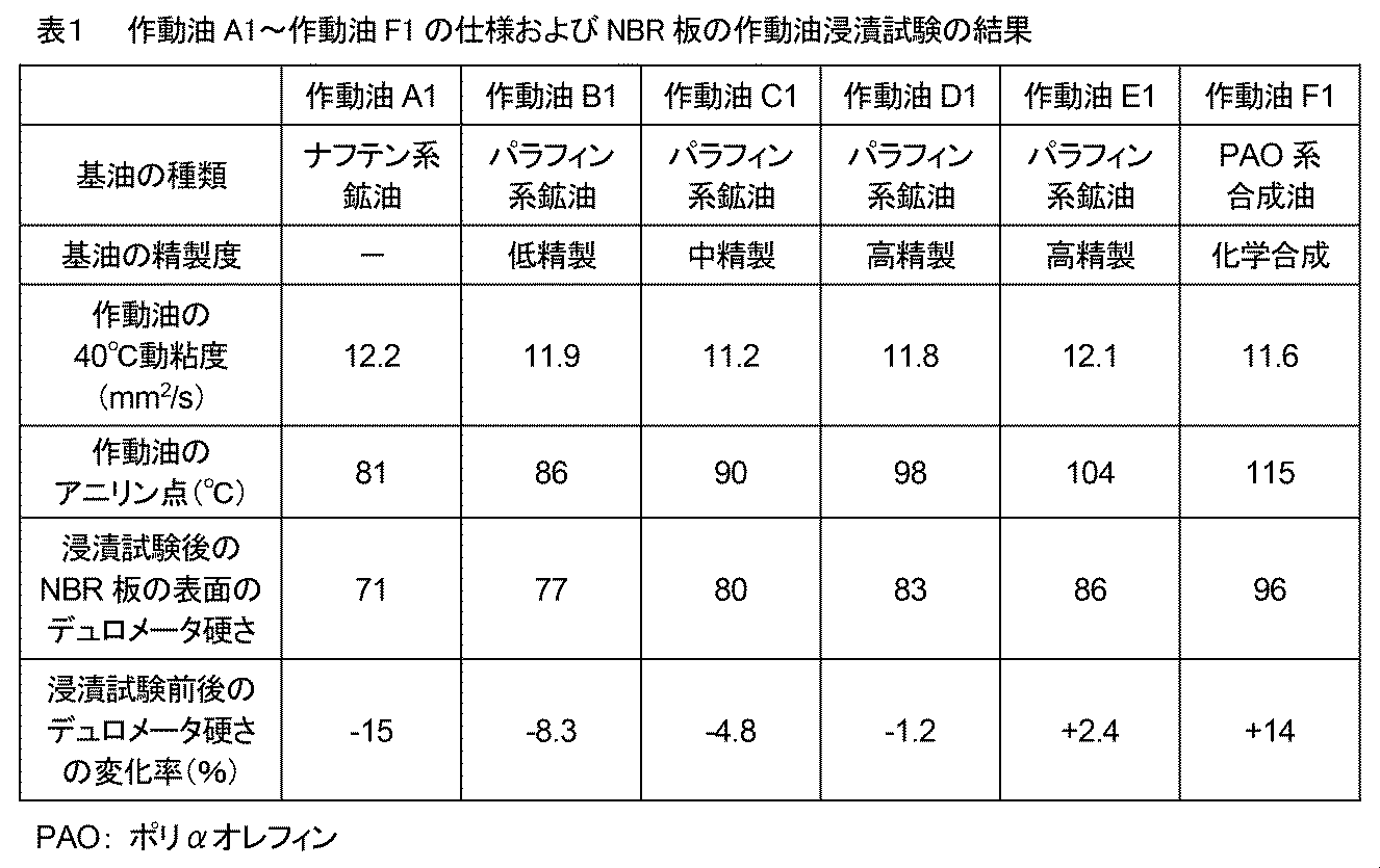
表1に示したように、作動油のアニリン点によって浸漬試験後のNBR板の表面硬さが変化することが分かる。具体的には、作動油のアニリン点が比較的低いと浸漬試験によってNBR板の表面が軟化し、作動油のアニリン点が比較的高いと浸漬試験によってNBR板の表面が硬化する。これは、アニリン点が低いと、作動油がシール材料内に浸透し易くなってシール材料を膨潤・軟化させ、アニリン点が高いと、シール材料内の成分が作動油に溶出し易くなってシール材料を収縮・硬化させるため、と考えられる。
[実験2]
(ダスト混合作動油を用いた摺動試験)
本実験では、ダストを混合させた作動油を用いて摺動試験を行い、シール材料に傷が入るか否か(耐傷性)を調査した。試験用ダストとしては、JIS Z 8901試験用粉体1の7種(関東ローム)を用いた。実験1で用意した作動油A1~作動油F1に対して、基油100質量部に1質量部の割合で試験用ダストを混合・分散させて作動油A2~作動油F2を用意した。
(ダスト混合作動油を用いた摺動試験)
本実験では、ダストを混合させた作動油を用いて摺動試験を行い、シール材料に傷が入るか否か(耐傷性)を調査した。試験用ダストとしては、JIS Z 8901試験用粉体1の7種(関東ローム)を用いた。実験1で用意した作動油A1~作動油F1に対して、基油100質量部に1質量部の割合で試験用ダストを混合・分散させて作動油A2~作動油F2を用意した。
摺動試験は、ボールオンディスク摩擦摩耗試験機(英国PCS Instruments社、MTMトラクション試験機)を用いて行った。ボール試験片として直径3/4インチのSUJ2(高炭素クロム軸受鋼)を用い、ディスク試験片として実験1と同種のNBR板を用いた。他の試験条件は、荷重5 N、周速度0.5 m/s、摺動時間5時間とし、ダスト混合作動油を摺動面に適宜滴下した。滴下するダスト混合作動油の油温は、10℃と80℃の二種類で行った。
摺動試験の後、NBR板の表面を光学顕微鏡で観察し、摺動方向の傷の有無および傷ありの場合の傷の長さを測定した。摺動方向の傷が観察・確認できなかったものを「傷なし」と判定し、摺動方向に長さ10 mm未満の傷が観察・確認されたものを「小傷あり」と判定し、摺動方向に長さ10 mm以上の傷が観察・確認されたものを「大傷あり」と判定した。実験2の試験結果を表2にまとめる。なお、表2には、表1の結果の一部を併記してある。
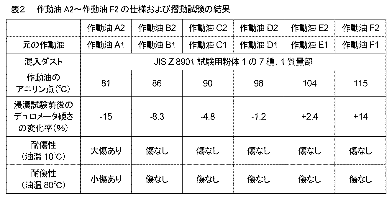
表2に示したように、作動油A2を用いた摺動試験では、試験後のNBR板の表面に大小の傷が観察・確認され、シール材料の耐傷性を低下させていることが分かる。言い換えると、作動油のアニリン点が85℃未満であり、シール材料との接触によりシール材料の表面硬さを10%超で軟化させる作動油A2は、シール材料の耐傷性を低下させることが確認される。なお、油温80℃の摺動試験での耐傷性が油温10℃のそれよりも相対的によかった理由は、温度の高さに起因してディスク試験片であるNBR板の変形量が大きくなってボール試験片との接触面積が増加し、ボール試験片との接触面圧が低下したためと考えられる。
一方、作動油のアニリン点が85℃以上であり、接触によるシール材料表面の軟化が少ない作動油B2~作動油F2では、シール材料の耐傷性に特段の悪影響はなかった。なお、ボールオンディスク摩擦摩耗試験機による摺動試験は、強制的に荷重を掛ける試験であることから、作動油F2を用いたことによるシール材料の収縮・硬化に起因する作動油密閉性の低下を判定・評価することはできない。
[実験3]
(シール材料の耐傷性に関するリン酸エステル類および本発明での添加剤の影響調査)
本実験では、リン酸エステル類および本発明での添加剤(ジアルキルジチオリン酸亜鉛、ボロン含有アルケニルコハク酸イミド)がシール材料の耐傷性に与える影響について調査した。
(シール材料の耐傷性に関するリン酸エステル類および本発明での添加剤の影響調査)
本実験では、リン酸エステル類および本発明での添加剤(ジアルキルジチオリン酸亜鉛、ボロン含有アルケニルコハク酸イミド)がシール材料の耐傷性に与える影響について調査した。
実験2で用意した作動油C2(ダストを含む作動油)をベースとし、基油100質量部に対して、0~2質量部のリン酸エステル類、0.1~0.5質量部のジアルキルジチオリン酸亜鉛、および0.1~0.5質量部のボロン含有アルケニルコハク酸イミドを添加して、作動油C3a~C3gを用意した。リン酸エステル類としてはトリクレジルホスフェートを用いた。ジアルキルジチオリン酸亜鉛としてはジ(2-エチルヘキシル)ジチオリン酸亜鉛を用いた。ボロン含有アルケニルコハク酸イミドとしてはボロン含有ポリブテニルコハク酸イミドを用いた。作動油C3a~C3gの仕様を後述する表3に示す。
まず、実験1と同様にして、作動油C3a~C3gの40℃動粘度およびアニリン点を調査した。また、実験2と同様の摺動試験を行ってシール材料の耐傷性への影響を調査した。摺動試験条件は、実験2において傷が入り易かった油温10℃とした。結果を表3に併記する。
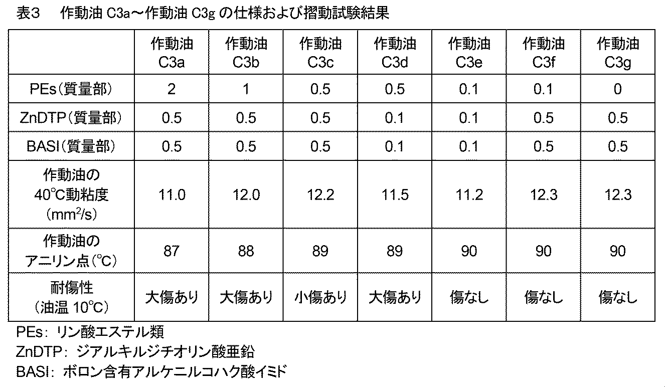
表3に示したように、リン酸エステル類を0.5質量部以上添加すると、作動油のアニリン点を少し下げる傾向があることが分かる。また、リン酸エステル類を0.5質量部以上添加した作動油C3a~作動油C3dは、摺動試験後のNBR板の表面に大小の傷が観察・確認され、シール材料の耐傷性を低下させていることが分かる。
一方、ジアルキルジチオリン酸亜鉛およびボロン含有アルケニルコハク酸イミドの添加は、作動油のアニリン点に影響を及ぼしていないと考えられる。また、リン酸エステル類の添加量を0.1質量部以下に抑えた作動油C3e~作動油C3gでは、シール材料の耐傷性に特段の悪影響がないことが確認される。
[実験4]
(耐摩耗性に関するリン酸エステル類および本発明での添加剤の影響調査)
前述したように、従来の作動油では、リン酸エステル類は耐摩耗性の向上に寄与する重要な成分として添加されてきた。本実験では、リン酸エステル類および本発明での添加剤(ジアルキルジチオリン酸亜鉛、ボロン含有アルケニルコハク酸イミド)が摺動部位の耐摩耗性に与える影響について調査した。
(耐摩耗性に関するリン酸エステル類および本発明での添加剤の影響調査)
前述したように、従来の作動油では、リン酸エステル類は耐摩耗性の向上に寄与する重要な成分として添加されてきた。本実験では、リン酸エステル類および本発明での添加剤(ジアルキルジチオリン酸亜鉛、ボロン含有アルケニルコハク酸イミド)が摺動部位の耐摩耗性に与える影響について調査した。
実験1で用意した作動油C1(ダストを含まない作動油)をベースとし、基油100質量部に対して、0~0.5質量部のリン酸エステル類、0~5質量部のジアルキルジチオリン酸亜鉛、および0~5質量部のボロン含有アルケニルコハク酸イミドを添加して、作動油C4a~C4jを用意した。リン酸エステル類、ジアルキルジチオリン酸亜鉛、およびボロン含有アルケニルコハク酸イミドは実験3と同じものを用いた。作動油C4a~C4jの仕様を後述する表4~表6に示す。基準試料として作動油C1単体も別途利用した。
まず、摺動試験の前に、各作動油の外観チェック(透明または不透明のチェック)を目視で行った。透明の作動油を用いて摺動試験を行い、不透明の作動油は添加剤が十分に溶解できなかったと判断して、摺動試験を行わなかった。
耐摩耗性を調査する摺動試験は、シリンダチューブとピストンシールとの摺動を想定して往復動摩擦試験機(ブルカージャパン株式会社、UMT TriboLab)を用いて行った。固定試験片としてポリテトラフルオロエチレン片(厚さ8 mm、シリカ充填剤15質量%含有、タイプAデュロメータ硬さ90)を用い、可動試験片としてS45C片(機械構造用炭素鋼、表面の算術平均粗さRa約0.2μm)を用いた。S45C片表面の算術平均粗さRaを約0.2μmとした理由は、加速試験のためである。他の試験条件は、可動試験片温度60℃、面圧4 MPa、ストローク10 mm、周波数5 Hz、摺動時間5時間、および作動油20μLを摺動面に塗布、とした。
摺動試験の後、ポリテトラフルオロエチレン片の厚さをマイクロメータで測定し、変位量を摩耗量(単位μm)とした。また、S45C片の質量を精密電子天秤で測定し、変化量を摩耗量(単位mg)とした。結果を表4~表6に併記する。
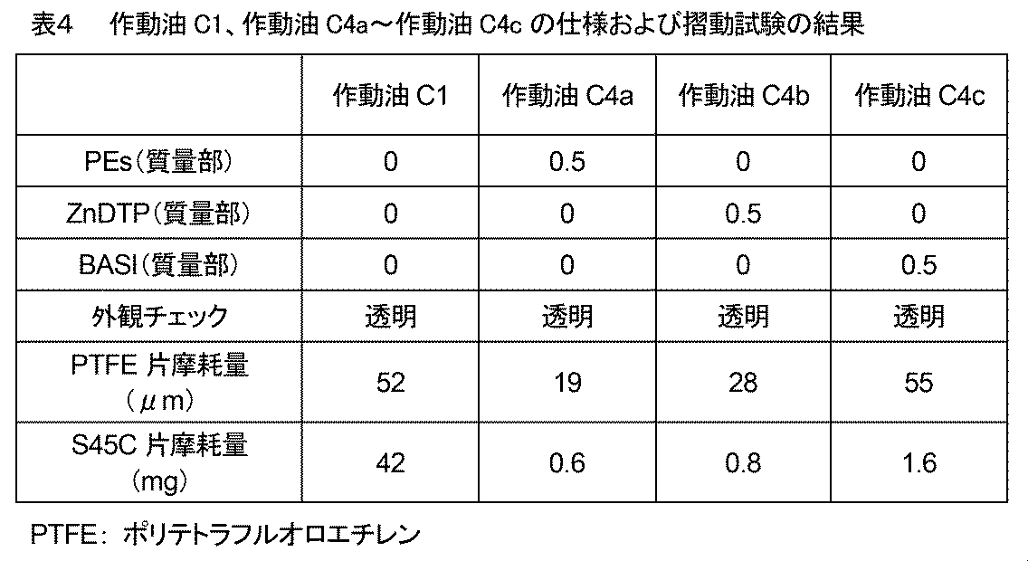
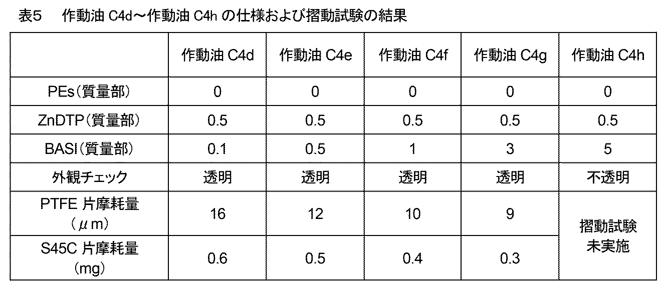
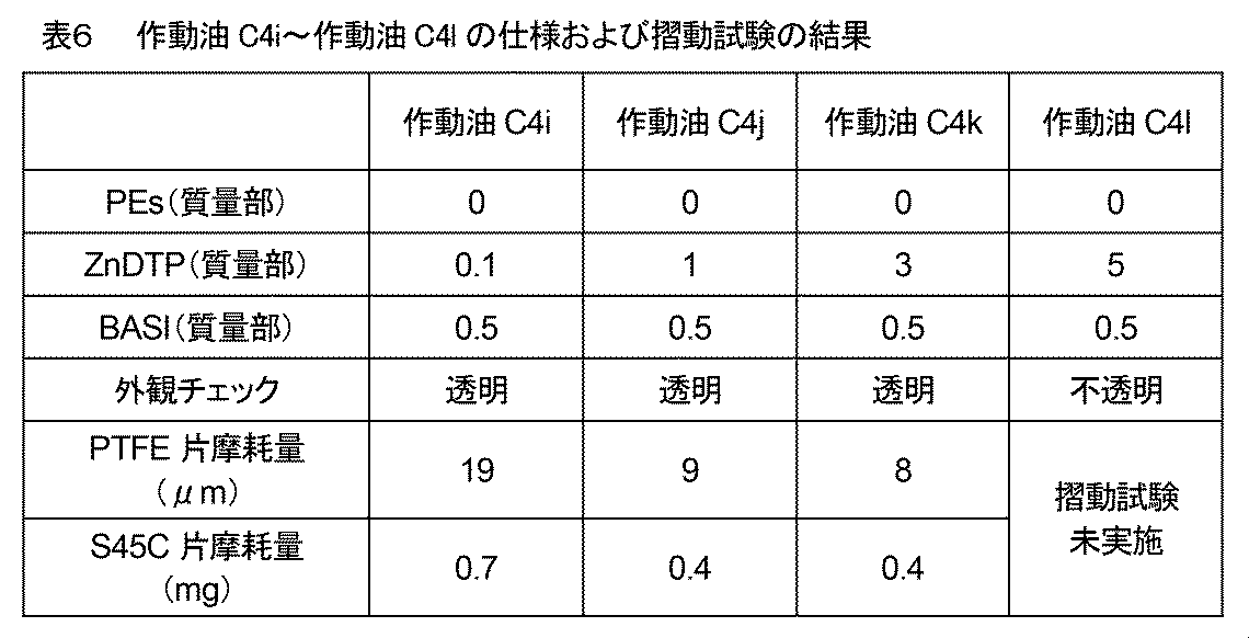
表4に示したように、耐摩耗剤が添加されていない作動油C1を用いた摺動試験では、PTFE片摩耗量およびS45C片摩耗量が共に非常に大きな値である。これに対し、従来の耐摩耗剤であるリン酸エステル類を添加した作動油C4aを用いた摺動試験では、PTFE片摩耗量およびS45C片摩耗量が共に作動油C1のそれらに比して大きく減少しており、耐摩耗剤としての従来からの効果が再確認される。
作動油C4bおよび作動油C4cは、本発明での添加剤であるジアルキルジチオリン酸亜鉛またはボロン含有アルケニルコハク酸イミドを単独で添加したものである。それらを用いた摺動試験では、作動油C4aでのPTFE片摩耗量およびS45C片摩耗量に比して増加しており、当該添加剤の単独添加はリン酸エステル類の代替えにならないことが分かる。
一方、表5~表6に示したように、ジアルキルジチオリン酸亜鉛およびボロン含有アルケニルコハク酸イミドを共添加した作動油C4d~作動油C4gおよび作動油C4i~作動油C4kでは、PTFE片摩耗量およびS45C片摩耗量が作動油C4aの場合に比して減少していることが分かる。当該添加剤の共添加は、耐摩耗性の向上に効果的であることが確認される。
ただし、それらの添加剤を3質量部超で添加した作動油C4hおよび作動油C4lは、外観チェックにおいて不透明になっていることが確認され、それらの添加剤も過剰添加は好ましくないと言える。
以上の各実験結果から、本発明に係る作動油は、油圧シリンダ装置における摺動部位において、従来の作動油と同等以上の耐摩耗性を確保しながら、シール材料の耐久性(特に耐傷性)を向上させられることが確認された。また、本発明に係る作動油を用いることにより、従来よりも摺動部位の耐摩耗性および耐久性が向上した油圧シリンダ装置を提供することができる。
上述した実施形態や実験は、本発明の理解を助けるために説明したものであり、本発明は、記載した具体的な構成のみに限定されるものではない。例えば、実施形態の構成の一部を当業者の技術常識の構成に置き換えることが可能であり、また、実施形態の構成に当業者の技術常識の構成を加えることも可能である。すなわち、本発明は、本明細書の実施形態や実験の構成の一部について、発明の技術的思想を逸脱しない範囲で、削除・他の構成に置換・他の構成の追加をすることが可能である。
100…自動車用油圧緩衝器、
10…筒部、20…外筒、30…内筒、32…ベースバルブ、
40…ピストン、42…ピストンバルブ、44…ピストンシール、
50…ピストンロッド、60…作動油、
70…ロッドガイド、72…ガイドブッシュ、74…ロッドシール。
10…筒部、20…外筒、30…内筒、32…ベースバルブ、
40…ピストン、42…ピストンバルブ、44…ピストンシール、
50…ピストンロッド、60…作動油、
70…ロッドガイド、72…ガイドブッシュ、74…ロッドシール。
Claims (10)
- 油圧シリンダ装置用の作動油であって、
基油と該基油に添加される添加剤とを含み、
前記作動油はアニリン点が85℃以上110℃以下の範囲にあり、
100質量部の前記基油に対して、前記添加剤として0.1質量部超のリン酸エステル類を含まない、
ことを特徴とする油圧シリンダ装置用作動油。 - 請求項1に記載の油圧シリンダ装置用作動油において、
前記添加剤として、100質量部の前記基油に対して、0.1質量部以上3質量部以下のジアルキルジチオリン酸亜鉛、および0.1質量部以上3質量部以下のボロン含有アルケニルコハク酸イミドを含むことを特徴とする油圧シリンダ装置用作動油。 - 請求項1又は請求項2に記載の油圧シリンダ装置用作動油において、
前記基油は鉱油および/または合成油であることを特徴とする油圧シリンダ装置用作動油。 - 請求項1乃至請求項3のいずれか一項に記載の油圧シリンダ装置用作動油において、
前記作動油の40℃における動粘度が8 mm2/s以上17 mm2/sであることであることを特徴とする油圧シリンダ装置用作動油。 - 請求項1乃至請求項4のいずれか一項に記載の油圧シリンダ装置用作動油において、
前記添加剤として、100質量部の前記基油に対して、0.01質量部超のリン酸エステル類を含まないことを特徴とする油圧シリンダ装置用作動油。 - 請求項1乃至請求項5のいずれか一項に記載の油圧シリンダ装置用作動油において、
前記添加剤として、油性向上剤、酸化防止剤、無灰系分散剤、金属系清浄分散剤、粘度指数向上剤、流動点降下剤、金属不活性化剤、防錆剤、および消泡剤から選ばれる一種以上を更に含むことを特徴とする油圧シリンダ装置用作動油。 - 作動油を用いた油圧シリンダ装置であって、
前記油圧シリンダ装置は、シリンダチューブと、該シリンダチューブの内側を往復運動可能なピストンと、該ピストンに固定されたピストンロッドと、該ピストンロッドが摺動するロッドシールとを有し、
前記ロッドシールは、アクリロニトリル含有量が24質量%以下のアクリロニトリル・ブタジエンゴムからなり、
前記作動油が請求項1乃至請求項6のいずれか一項に記載の油圧シリンダ装置用作動油である、
ことを特徴とする油圧シリンダ装置。 - 請求項7に記載の油圧シリンダ装置において、
前記ピストンロッドは、その表面に算術平均粗さが0.1μm以下のクロムめっき層が形成されていることを特徴とする油圧シリンダ装置。 - 請求項7又は請求項8に記載の油圧シリンダ装置において、
前記ロッドシールは、20℃におけるショアA硬度が75以上90以下であることを特徴とする油圧シリンダ装置。 - 請求項7乃至請求項9のいずれか一項に記載の油圧シリンダ装置において、
前記油圧シリンダ装置が自動車用油圧緩衝器であることを特徴とする油圧シリンダ装置。
Priority Applications (1)
| Application Number | Priority Date | Filing Date | Title |
|---|---|---|---|
| CN202480040440.1A CN121335967A (zh) | 2023-09-28 | 2024-06-17 | 液压缸装置用工作油以及液压缸装置 |
Applications Claiming Priority (2)
| Application Number | Priority Date | Filing Date | Title |
|---|---|---|---|
| JP2023-167777 | 2023-09-28 | ||
| JP2023167777A JP2025057932A (ja) | 2023-09-28 | 2023-09-28 | 油圧シリンダ装置用作動油および油圧シリンダ装置 |
Publications (1)
| Publication Number | Publication Date |
|---|---|
| WO2025069596A1 true WO2025069596A1 (ja) | 2025-04-03 |
Family
ID=95202799
Family Applications (1)
| Application Number | Title | Priority Date | Filing Date |
|---|---|---|---|
| PCT/JP2024/021828 Ceased WO2025069596A1 (ja) | 2023-09-28 | 2024-06-17 | 油圧シリンダ装置用作動油および油圧シリンダ装置 |
Country Status (3)
| Country | Link |
|---|---|
| JP (1) | JP2025057932A (ja) |
| CN (1) | CN121335967A (ja) |
| WO (1) | WO2025069596A1 (ja) |
Citations (9)
| Publication number | Priority date | Publication date | Assignee | Title |
|---|---|---|---|---|
| JPS55151094A (en) * | 1979-05-15 | 1980-11-25 | Nippon Oil Co Ltd | Fluid composition for vehicular central hydraulic system |
| JPS5624493A (en) * | 1979-08-06 | 1981-03-09 | Nippon Oil Co Ltd | Central system fluid composition for automobile |
| JPS60144393A (ja) * | 1983-07-20 | 1985-07-30 | Cosmo Co Ltd | 潤滑油又は作動油組成物 |
| JP2000044971A (ja) * | 1998-07-28 | 2000-02-15 | Idemitsu Kosan Co Ltd | 緩衝器用潤滑油組成物 |
| JP2010531923A (ja) * | 2007-06-28 | 2010-09-30 | シェブロン ユー.エス.エー. インコーポレイテッド | 機能性流体組成物 |
| JP2011021111A (ja) * | 2009-07-16 | 2011-02-03 | Cosmo Oil Lubricants Co Ltd | 緩衝器用油圧作動油組成物 |
| JP2016014091A (ja) * | 2014-07-01 | 2016-01-28 | 日本サン石油株式会社 | 油圧作動油組成物 |
| WO2018135645A1 (ja) * | 2017-01-19 | 2018-07-26 | 出光興産株式会社 | 潤滑油組成物 |
| JP2022022721A (ja) * | 2020-07-02 | 2022-02-07 | 出光興産株式会社 | 潤滑油組成物、緩衝器、及び潤滑油組成物の使用方法 |
-
2023
- 2023-09-28 JP JP2023167777A patent/JP2025057932A/ja active Pending
-
2024
- 2024-06-17 WO PCT/JP2024/021828 patent/WO2025069596A1/ja not_active Ceased
- 2024-06-17 CN CN202480040440.1A patent/CN121335967A/zh active Pending
Patent Citations (9)
| Publication number | Priority date | Publication date | Assignee | Title |
|---|---|---|---|---|
| JPS55151094A (en) * | 1979-05-15 | 1980-11-25 | Nippon Oil Co Ltd | Fluid composition for vehicular central hydraulic system |
| JPS5624493A (en) * | 1979-08-06 | 1981-03-09 | Nippon Oil Co Ltd | Central system fluid composition for automobile |
| JPS60144393A (ja) * | 1983-07-20 | 1985-07-30 | Cosmo Co Ltd | 潤滑油又は作動油組成物 |
| JP2000044971A (ja) * | 1998-07-28 | 2000-02-15 | Idemitsu Kosan Co Ltd | 緩衝器用潤滑油組成物 |
| JP2010531923A (ja) * | 2007-06-28 | 2010-09-30 | シェブロン ユー.エス.エー. インコーポレイテッド | 機能性流体組成物 |
| JP2011021111A (ja) * | 2009-07-16 | 2011-02-03 | Cosmo Oil Lubricants Co Ltd | 緩衝器用油圧作動油組成物 |
| JP2016014091A (ja) * | 2014-07-01 | 2016-01-28 | 日本サン石油株式会社 | 油圧作動油組成物 |
| WO2018135645A1 (ja) * | 2017-01-19 | 2018-07-26 | 出光興産株式会社 | 潤滑油組成物 |
| JP2022022721A (ja) * | 2020-07-02 | 2022-02-07 | 出光興産株式会社 | 潤滑油組成物、緩衝器、及び潤滑油組成物の使用方法 |
Also Published As
| Publication number | Publication date |
|---|---|
| JP2025057932A (ja) | 2025-04-09 |
| CN121335967A (zh) | 2026-01-13 |
Similar Documents
| Publication | Publication Date | Title |
|---|---|---|
| JP5284372B2 (ja) | 等速ジョイントに使用されるグリース組成物 | |
| KR102329652B1 (ko) | 윤활 첨가제 조성물, 이것을 함유하는 윤활성 조성물 및 그 윤활성 조성물로 이루어지는 엔진 오일 조성물 | |
| US5364545A (en) | Lubricating oil composition containing friction modifier and corrosion inhibitor | |
| US20070292711A1 (en) | Low Friction Sliding Mechanism | |
| US20250154427A1 (en) | Lubricating oil composition and sliding mechanism | |
| US20050221998A1 (en) | Low viscosity, high abrasion resistance engine oil composition | |
| WO2018139130A1 (ja) | 変速機用潤滑油組成物、変速機の潤滑方法及び変速機 | |
| WO2015025977A1 (ja) | 緩衝器用潤滑油組成物 | |
| JPH05255683A (ja) | 緩衝器用油圧作動油組成物 | |
| WO2018003247A1 (ja) | 油圧装置用作動油およびその油圧装置用作動油を用いた油圧装置 | |
| US20230250357A1 (en) | Lubricating oil composition, shock absorber, and method for using lubricating oil composition | |
| JP2025057932A (ja) | 油圧シリンダ装置用作動油および油圧シリンダ装置 | |
| JPH05255682A (ja) | 油圧作動油組成物 | |
| JP7264616B2 (ja) | 緩衝器用潤滑油組成物、緩衝器用潤滑油の摩擦調整用添加剤および潤滑油添加剤 | |
| JP3254279B2 (ja) | 油圧作動油組成物 | |
| JP7261074B2 (ja) | 油圧装置用作動油及びその油圧装置用作動油を用いた油圧装置 | |
| WO2019093238A1 (ja) | 緩衝器用潤滑油組成物、緩衝器の摩擦低減方法および緩衝器用潤滑油組成物の製造方法 | |
| US20150225665A1 (en) | Ashless type engine oil composition | |
| JP5483301B2 (ja) | 緩衝器用油圧作動油組成物 | |
| JP5087262B2 (ja) | 自動車緩衝器用潤滑油組成物 | |
| JP7089899B2 (ja) | 潤滑油組成物、潤滑油組成物の製造方法及び駆動系機器 | |
| WO2026083671A1 (ja) | 油圧シリンダ装置 | |
| JP2008255355A (ja) | 磨耗特性を向上させるコーティング | |
| JPH09176672A (ja) | 緩衝器用油圧作動油組成物 | |
| JPH0411694A (ja) | 緩衝器用潤滑油組成物 |
Legal Events
| Date | Code | Title | Description |
|---|---|---|---|
| 121 | Ep: the epo has been informed by wipo that ep was designated in this application |
Ref document number: 24871401 Country of ref document: EP Kind code of ref document: A1 |
|
| NENP | Non-entry into the national phase |
Ref country code: DE |