WO2025057790A1 - X線発生装置およびx線撮像装置 - Google Patents
X線発生装置およびx線撮像装置 Download PDFInfo
- Publication number
- WO2025057790A1 WO2025057790A1 PCT/JP2024/031346 JP2024031346W WO2025057790A1 WO 2025057790 A1 WO2025057790 A1 WO 2025057790A1 JP 2024031346 W JP2024031346 W JP 2024031346W WO 2025057790 A1 WO2025057790 A1 WO 2025057790A1
- Authority
- WO
- WIPO (PCT)
- Prior art keywords
- ray generating
- tube
- insulating
- space
- insulating tube
- Prior art date
- Legal status (The legal status is an assumption and is not a legal conclusion. Google has not performed a legal analysis and makes no representation as to the accuracy of the status listed.)
- Pending
Links
Images








Classifications
-
- H—ELECTRICITY
- H05—ELECTRIC TECHNIQUES NOT OTHERWISE PROVIDED FOR
- H05G—X-RAY TECHNIQUE
- H05G1/00—X-ray apparatus involving X-ray tubes; Circuits therefor
- H05G1/02—Constructional details
- H05G1/04—Mounting the X-ray tube within a closed housing
-
- G—PHYSICS
- G01—MEASURING; TESTING
- G01N—INVESTIGATING OR ANALYSING MATERIALS BY DETERMINING THEIR CHEMICAL OR PHYSICAL PROPERTIES
- G01N23/00—Investigating or analysing materials by the use of wave or particle radiation, e.g. X-rays or neutrons, not covered by groups G01N3/00 – G01N17/00, G01N21/00 or G01N22/00
- G01N23/02—Investigating or analysing materials by the use of wave or particle radiation, e.g. X-rays or neutrons, not covered by groups G01N3/00 – G01N17/00, G01N21/00 or G01N22/00 by transmitting the radiation through the material
- G01N23/04—Investigating or analysing materials by the use of wave or particle radiation, e.g. X-rays or neutrons, not covered by groups G01N3/00 – G01N17/00, G01N21/00 or G01N22/00 by transmitting the radiation through the material and forming images of the material
-
- H—ELECTRICITY
- H01—ELECTRIC ELEMENTS
- H01J—ELECTRIC DISCHARGE TUBES OR DISCHARGE LAMPS
- H01J35/00—X-ray tubes
- H01J35/02—Details
-
- H—ELECTRICITY
- H01—ELECTRIC ELEMENTS
- H01J—ELECTRIC DISCHARGE TUBES OR DISCHARGE LAMPS
- H01J35/00—X-ray tubes
- H01J35/02—Details
- H01J35/025—X-ray tubes with structurally associated circuit elements
-
- H—ELECTRICITY
- H01—ELECTRIC ELEMENTS
- H01J—ELECTRIC DISCHARGE TUBES OR DISCHARGE LAMPS
- H01J35/00—X-ray tubes
- H01J35/02—Details
- H01J35/04—Electrodes ; Mutual position thereof; Constructional adaptations therefor
- H01J35/06—Cathodes
- H01J35/064—Details of the emitter, e.g. material or structure
-
- H—ELECTRICITY
- H01—ELECTRIC ELEMENTS
- H01J—ELECTRIC DISCHARGE TUBES OR DISCHARGE LAMPS
- H01J35/00—X-ray tubes
- H01J35/02—Details
- H01J35/16—Vessels; Containers; Shields associated therewith
-
- H—ELECTRICITY
- H05—ELECTRIC TECHNIQUES NOT OTHERWISE PROVIDED FOR
- H05G—X-RAY TECHNIQUE
- H05G1/00—X-ray apparatus involving X-ray tubes; Circuits therefor
- H05G1/02—Constructional details
-
- H—ELECTRICITY
- H05—ELECTRIC TECHNIQUES NOT OTHERWISE PROVIDED FOR
- H05G—X-RAY TECHNIQUE
- H05G1/00—X-ray apparatus involving X-ray tubes; Circuits therefor
- H05G1/02—Constructional details
- H05G1/04—Mounting the X-ray tube within a closed housing
- H05G1/06—X-ray tube and at least part of the power supply apparatus being mounted within the same housing
-
- G—PHYSICS
- G01—MEASURING; TESTING
- G01N—INVESTIGATING OR ANALYSING MATERIALS BY DETERMINING THEIR CHEMICAL OR PHYSICAL PROPERTIES
- G01N2223/00—Investigating materials by wave or particle radiation
- G01N2223/10—Different kinds of radiation or particles
- G01N2223/101—Different kinds of radiation or particles electromagnetic radiation
- G01N2223/1016—X-ray
-
- G—PHYSICS
- G01—MEASURING; TESTING
- G01N—INVESTIGATING OR ANALYSING MATERIALS BY DETERMINING THEIR CHEMICAL OR PHYSICAL PROPERTIES
- G01N2223/00—Investigating materials by wave or particle radiation
- G01N2223/20—Sources of radiation
- G01N2223/204—Sources of radiation source created from radiated target
-
- H—ELECTRICITY
- H01—ELECTRIC ELEMENTS
- H01J—ELECTRIC DISCHARGE TUBES OR DISCHARGE LAMPS
- H01J2235/00—X-ray tubes
- H01J2235/16—Vessels
- H01J2235/165—Shielding arrangements
- H01J2235/166—Shielding arrangements against electromagnetic radiation
-
- H—ELECTRICITY
- H01—ELECTRIC ELEMENTS
- H01J—ELECTRIC DISCHARGE TUBES OR DISCHARGE LAMPS
- H01J35/00—X-ray tubes
- H01J35/02—Details
- H01J35/04—Electrodes ; Mutual position thereof; Constructional adaptations therefor
- H01J35/08—Anodes; Anti cathodes
- H01J35/112—Non-rotating anodes
Definitions
- the present invention relates to an X-ray generating device and an X-ray imaging device.
- Patent Document 1 describes an X-ray generating device that includes an X-ray generating tube, a tube drive circuit that drives the X-ray generating tube, and a container that houses the X-ray generating tube and the tube drive circuit.
- the container is filled with an insulating liquid that ensures insulation between the X-ray generating tube and the tube drive circuit.
- abnormal discharges can occur in the X-ray generating tube.
- An investigation by the inventors revealed that abnormal discharges occur between the cathode and anode of the X-ray generating tube through the outer surface of the insulating tube. Abnormal discharges can cause the X-ray generating device to stop or break down.
- One aspect of the present invention provides an advantageous technique for suppressing the occurrence of abnormal discharges in an X-ray generating device.
- a first aspect of the present invention relates to an X-ray generating device, the X-ray generating device comprising: an X-ray generating tube having an insulating tube having a first opening end and a second opening end; a cathode arranged to close the first opening end of the insulating tube and including an electron emitting portion; and an anode arranged to close the second opening end and including a target that generates X-rays when electrons from the electron emitting portion collide with the target; and a container that contains the X-ray generating tube and a driving circuit, the container having a first space that contains at least a portion of the X-ray generating tube, and a second space that contains the driving circuit.
- the container has a third open end
- the X-ray generating tube is disposed so as to close the third open end
- an insulating liquid is filled in the container so as to contact a part of the insulating tube
- the insulating tube has a boundary surface that constitutes the outer surface of the X-ray generating tube
- a first member disposed at a distance from the second open end contacts at least a part of the boundary surface, and the first member is sandwiched between the insulating tube and a second member disposed at a distance from the container.
- a second aspect of the present invention relates to an X-ray generating device, comprising: an X-ray generating tube having an insulating tube having a first opening end and a second opening end; a cathode arranged to close the first opening end of the insulating tube and including an electron emitting portion; and an anode arranged to close the second opening end and including a target that generates X-rays when electrons from the electron emitting portion collide with the target; and a container that contains the X-ray generating tube and a drive circuit, the container having a first space that contains at least a portion of the X-ray generating tube and a second space that contains the drive circuit.
- the first space is disposed so as to protrude from the second space
- the container has a third opening end
- the X-ray generating tube is disposed so as to close the third opening end
- an insulating liquid is filled in the container so as to contact a part of the insulating tube
- the insulating tube includes a boundary surface constituting the outer surface of the X-ray generating tube and an inner surface facing the internal space of the X-ray generating tube
- the boundary surface includes an enclosing surface facing the space enclosed by the insulating tube
- a third space is defined so as to be surrounded by the enclosing surface of the boundary surface and the bottom surface of the cathode.
- the third aspect of the present invention relates to an X-ray imaging device, which includes an X-ray generating device according to the first aspect, and an X-ray detector that detects X-rays emitted from the X-ray generating device.
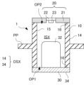
- FIG. 1 is a diagram illustrating a schematic configuration of a conventional X-ray generating device, for explaining the basic configuration of an X-ray generating device according to the present disclosure.
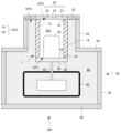
- 1 is a diagram exemplarily and diagrammatically illustrating the configuration of an X-ray generating device according to a first embodiment
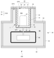
- FIG. 10 is a diagram exemplarily and diagrammatically illustrating the configuration of an X-ray generating device according to a second embodiment.
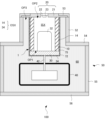
- FIG. 11 is a diagram exemplarily and diagrammatically illustrating the configuration of an X-ray generating device according to a third embodiment.
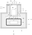
- FIG. 13 is a diagram exemplarily and diagrammatically illustrating the configuration of an X-ray generating device according to a fourth embodiment.
- FIG. 4 is a diagram showing the occurrence of abnormal discharge.
- FIG. 2 is a diagram illustrating a triboelectric series in frictional electrification with an insulating liquid.
- 13A to 13C are diagrams showing problems in the X-ray generating device according to the fifth embodiment.
- FIG. 13 is a diagram exemplarily and diagrammatically illustrating the configuration of an X-ray generating device according to a fifth embodiment.
- FIG. 13 is a diagram illustrating a configuration of a first modified example of an X-ray generating device according to the fifth embodiment.
- FIG. 13 is a diagram illustrating a configuration of a second modified example of the X-ray generating device according to the fifth embodiment.
- FIG. 13 is a diagram illustrating a configuration of a third modified example of the X-ray generating device according to the fifth embodiment.
- FIG. 13 is a diagram illustrating a configuration of a fourth modified example of the X-ray generation device according to the fifth embodiment.
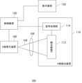
- FIG. 1 is a diagram showing the configuration of an X-ray imaging apparatus according to an embodiment.
- FIG. 13 is a diagram illustrating a configuration of a fifth modified example of the X-ray generating device according to the fifth embodiment.
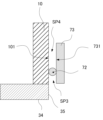
- FIG. 15B is an enlarged schematic diagram of a portion of FIG. 15A.
- FIG. 13 is a diagram illustrating a configuration of a sixth modified example of the X-ray generating device according to the fifth embodiment.
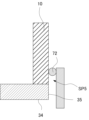
- FIG. 16B is a schematic diagram showing an enlarged portion of FIG. 16A.
- FIG. 13 is a diagram illustrating a configuration of a seventh modified example of the X-ray generating device according to the fifth embodiment.
- the X-ray generating device 100 may include an X-ray generating tube 1 and a container 50 that contains the X-ray generating tube 1.
- the X-ray generating device 100 may further include a drive circuit 40 that drives the X-ray generating tube 1, and the drive circuit 40 may be contained in the container 50 and connected to the X-ray generating tube 1 via a cable 42.
- a part of the X-ray generating tube 1 (anode 20 described below) may be exposed to the external space of the container 50 (external space of the X-ray generating device 100).
- the internal space of the container 50 is filled with an insulating liquid 60.
- the internal space of the container 50 is filled with the insulating liquid 60, except for the space occupied by the components (X-ray generating tube 1, cable 42, etc.) contained in the container 50.
- the insulating liquid 60 may be, for example, an insulating oil such as mineral oil or chemically synthesized oil.
- the insulating liquid 60 may be a liquid other than insulating oil, such as a fluorine-based inert liquid (e.g., Fluorinert (trademark)).
- the X-ray generating tube 1 may include an insulating tube 10, a cathode 30, and an anode 20.
- the insulating tube 10, the cathode 30, and the anode 20 may be configured to define an internal space ISX of the X-ray generating tube 1.
- the internal space ISX of the X-ray generating tube 1 is maintained in a vacuum.
- the insulating tube 10 may have a first open end OP1 and a second open end OP2.
- the insulating tube 10 may have a tubular shape, such as a cylindrical shape.
- the insulating tube 10 may be configured to provide vacuum tightness and insulation for the internal space ISX that may be defined by the insulating tube 10, the cathode 30, and the anode 20.
- the insulating tube 10 may be made of a ceramic material, for example, whose main component is alumina or zirconia. Alternatively, the insulating tube 10 may be made of a glass material, such as borosilicate glass.
- the cathode 30 may be arranged to close the first open end OP1 of the insulating tube 10.
- the cathode 30 includes an electron emitter 32.
- the anode 20 may be arranged to close the second open end OP2 of the insulating tube 10.
- the anode 20 may include a target 23 that generates X-rays when electrons from the electron emitter 32 collide with the target 23.
- the anode 20 may include a target holding plate 22 that holds the target 23 and an electrode 21 that supports the target holding plate 22.
- the electrode 21 is made of a conductor, is electrically connected to the target 23, and applies a potential to the target 23.
- the anode 20 and the container 50 may be maintained at, for example, a ground potential, but may also be maintained at another potential.
- the target 23 may be made of a material that has a high melting point and high X-ray generation efficiency, such as tungsten, tantalum, or molybdenum.
- the target holding plate 22 may be made of a material that is easy to transmit X-rays, such as beryllium, diamond, etc.
- the container 50 may have a third opening end OP3.
- the container 50 may include, for example, a first portion 52, a second portion 53, a third portion 54, a fourth portion 55, and a fifth portion 56.
- the first portion 52 may have a tubular shape, such as a cylindrical shape.
- the first portion 52 may define the third opening end OP3 of the container 50.
- the first portion 52 may have a third opening end OP3.
- the second portion 53 is made of a conductor and is electrically connected to the anode 20 of the X-ray generating tube 1.
- the second portion 53 may be understood as constituting an anode together with the electrode 21.
- the second portion 53 may have a ring shape or a frame shape.
- the second portion 53 may be arranged so as to be in contact with the insulating liquid 60.
- the conductive member including the electrode 21 and the second portion 53 may be arranged so as to be in contact with the insulating liquid 60.
- the electrode 21 and the second portion 53 may be constructed as a single piece of the same material.
- the fourth portion 55 may have a tubular shape, such as a cylindrical shape or a square tube shape.
- the third portion 54 may be connected to one end of the fourth portion 55 and may have a ring shape or a frame shape.
- the first portion 52 may be connected to the third portion 54 so as to protrude from the third portion 54.
- the fifth portion 56 may be connected to the other end of the fourth portion 55.
- the third portion 54, the fourth portion 55, and the fifth portion 56 may be integrated to have a hollow spherical shape, except for the joint portion with the first portion 52.
- the insulating liquid 60 can convect in the internal space of the container 50.
- the insulating tube 10 has an outer surface (boundary surface) 14 constituting the outer surface OSX of the X-ray generating tube 1, an inner surface 15 facing the internal space ISX (vacuum space) of the X-ray generating tube 1, and a contact surface 16 in contact with other members (e.g., the cathode 30, the anode 20) constituting the internal space ISX (vacuum space) of the X-ray generating tube 1.
- the outer surface OSX includes the outer surface (boundary surface) 14 and the outer surface 34 of the cathode 30.
- the outer surface 14 of the insulating tube 10 is a surface of the entire surface of the insulating tube 10 that is neither the inner surface 15 nor the contact surface 16.
- the insulating tube 10 and the insulating liquid 60 can be charged due to friction between the outer surface 14 of the insulating tube 10 and the insulating liquid 60.
- Such charging is called frictional charging.
- triboelectric charging refers to a phenomenon in which electric charges are transferred between two different materials due to friction between the two materials, and one material is charged positively and the other material is charged negatively.
- the inventor conducted an experiment in which an insulating tube was left in convecting insulating oil (insulating liquid) and then the electric potential of the outer surface of the insulating tube was measured using a surface electrometer. As a result, it was confirmed that the outer surface of the insulating tube was charged positively and that the amount of charge increased in proportion to time.
- the polarity of the charge due to friction depends on the characteristics of the rubbing material.
- the characteristics of the material include the triboelectric series and the relative dielectric constant.
- Figure 7 shows an example of the triboelectric series for insulating oil.
- the triboelectric series indicates whether the rubbed material is charged positively or negatively, and the order of ease of charging. In the triboelectric series, materials located more on the positive polarity side are more likely to be charged positively, and materials located more on the negative polarity side are more likely to be charged negatively.
- the insulating performance between the cathode 30 and the anode 20 may be reduced by the outer surface 14 of the insulating tube 10 being positively charged.
- the insulating performance between the cathode 30 and the anode 20 may depend on the potential difference between the cathode 30 and the anode 20, the resistance between the cathode 30 and the anode 20, the distance between the cathode 30 and the anode 20, and the like.
- As a result of the experiment it was found that when the insulating tube 10 is positively charged, the cathode 30 and the anode 20 are short-circuited via the outer surface 14 of the insulating tube 10, as shown diagrammatically by the thick arrow in FIG. 6.
- abnormal discharge is likely to occur due to electron avalanches when the outer surface 14 of the insulating tube 10, the cathode 30, and the insulating liquid 60 form a triple point.
- the container 50 may be filled with an insulating liquid 60 so as to contact a portion of the anode (e.g., the second portion 53) and cover the outer surface 14 of the insulating tube 10 and the outer surface 34 of the cathode 30.
- a portion of the insulating tube 10 is surrounded by a member 72 so as to reduce abnormal discharge between the cathode 30 and the anode 20 through the insulating tube 10.
- the member 72 may be made of an insulating material.
- the entire outer surface 34 of the insulating tube 10 may be surrounded by the member 72.
- the entire outer surface 14 of the insulating tube 10 may be covered by the member 72.
- the entire outer surface 34 of the cathode 30 may be covered by the member 72.
- the first embodiment is effective in preventing the outer surface 14 of the insulating tube 10, the cathode 30, and the insulating liquid 60 from forming a triple point, which can reduce the occurrence of abnormal discharge.
- the material of the member 72 may be determined so that the member 72 is negatively charged by frictional charging between the member 72 and the insulating liquid 60, and the insulating liquid 60 is positively charged.
- the material of the member 72 may be selected so that the member 72 is negatively charged by frictional charging between the member 72 and the insulating oil, for example, according to the triboelectric series illustrated in FIG. 7.
- Suitable materials for the member 72 include, for example, polytetrafluoroethylene (Teflon (trademark)), PMMA (polymethylmethacrylate resin), epoxy, and fluororubber (for example, Viton (trademark)).
- the member 72 may be arranged to cover, for example, the entire outer surface 14 of the insulating tube 10 and the outer surface 34 of the cathode 30, and for this purpose, for example, a molding method, a spraying method, a dipping method, or the like may be applied.
- the material of the member 72 can be determined so that the relative dielectric constant difference between the member 72 and the insulating liquid 60 is smaller than the relative dielectric constant difference between the member 72 and the insulating tube 10.
- the member 72 is made of Viton with a relative dielectric constant of 3 or polytetrafluoroethylene with a relative dielectric constant of 2.1
- the insulating tube 10 is made of borosilicate glass with a relative dielectric constant of 4.9 or alumina with a relative dielectric constant of 9.
- the fact that the relative dielectric constant difference between the member 72 and the insulating liquid 60 is smaller than the relative dielectric constant difference between the member 72 and the insulating tube 10 may be evaluated at the temperature at which X-rays are generated or at room temperature (e.g., 25°C). However, there is no significant difference between the former and the latter.
- the material of the member 72 i.e., the covering material
- the material of the member 72 can be kneaded in advance by a kneading device with a base agent and a hardening assistant to prevent air bubbles from being introduced, and can be kept at a constant temperature to maintain appropriate flow.
- the temperature is, for example, around 100°C, but the temperature can be appropriately determined depending on the material used.
- the covering material can be poured into a container that is one size larger than the X-ray generating tube 1 to be covered.
- the covering material can be rapidly cooled due to the temperature difference between the container and the covering material, and the fluidity of the covering material can be reduced. To prevent this, it is desirable to heat the container in advance. After the covering material poured into the container overflows from the container, the amount of covering material can be solidified at an appropriate cooling rate and temperature distribution so that problems such as shrinkage do not occur.
- a high voltage is applied between the anode 20 and the cathode 30. If there are bubbles with a low dielectric constant in the member 72 made of the coating material, an electric field will concentrate there, which may induce abnormal discharge. To avoid this, the space in which the process of filling the coating material is performed can be evacuated in advance using a vacuum pump to a vacuum level of several hundred to several thousand Pa.
- a primer material may be applied to the surface of the X-ray generating tube 1, or unevenness may be formed by blasting, and then the coating with the member 72 may be performed.
- the thickness of the member 72 is thin from the viewpoint of heat dissipation of the X-ray generating tube 1.
- the thickness of the member 72 is preferably, for example, 5 mm or less, and more preferably 3 mm or less.
- the thickness of the member 72 is preferably, for example, 0.3 mm or more, and more preferably 0.5 mm or more.
- FIG. 3 exemplarily and typically illustrates the configuration of an X-ray generating device 100 according to a second embodiment.
- Items not mentioned in the explanation of the second embodiment may follow the basic configuration explained with reference to the first embodiment or FIG. 1.
- Member 72 may be arranged so as to cover contact portion C between cathode 30 and insulating tube 10.
- Member 72 may also be arranged so as to cover cathode 30.
- the second embodiment is also effective in preventing the outer surface 14 of insulating tube 10, cathode 30, and insulating liquid 60 from forming a triple point, which may reduce the occurrence of abnormal discharge.
- FIG. 4 exemplarily and typically illustrates the configuration of the X-ray generating device 100 of the third embodiment. Items not mentioned in the description of the third embodiment may follow the basic configuration described with reference to the first or second embodiment, or FIG. 1.
- an intermediate layer 75 is provided between the member 72 and the insulating tube 10.
- the intermediate layer 75 may be made of an insulating material.
- the intermediate layer 75 may be configured to cover the insulating tube 10.
- the member 72 may be configured to cover the intermediate layer 75.
- the intermediate layer 75 may be made of at least one of a mixture containing, for example, Kovar glass, nylon, and a metal oxide mainly composed of silica.
- Providing the intermediate layer 75 is advantageous for forming a smooth surface to cover, for example, the outer surface 14 of the insulating tube 10.
- forming the intermediate layer 75 is advantageous for preventing foreign matter from entering between the particles that make up the insulating tube 10.
- the creepage withstand voltage on the surface of the member 72 arranged to cover the insulating tube 10 can be improved. This prevents abnormal discharge and extends the life of the X-ray generating device 100.
- FIG. 5 exemplarily and typically illustrates the configuration of the X-ray generating device 100 of the fourth embodiment. Matters not mentioned in the description of the fourth embodiment may follow the basic configuration described with reference to the first to third embodiments or FIG. 1.
- the member 72 may include a ring-shaped portion.
- the member 72 may be a ring-shaped portion.
- the ring-shaped portion may surround a portion of the outer surface 14 of the insulating tube 10 in the axial direction (the axial direction of the insulating tube 10, which is also the direction in which the electron beam is emitted from the electron emission portion 32) over the entire circumference.
- the outer surface 14 of the insulating tube 10 may come into contact with the insulating liquid 60 in an area other than the area surrounded by the member 72. It is preferable that the shortest distance between the member 72 and the cathode 30 is smaller than the shortest distance between the member 72 and the anode 20.
- the insulating tube 10 may be surrounded by multiple members 72 (ring-shaped portions). The multiple members 72 may be arranged spaced apart from each other in the axial direction of the insulating tube 10.
- the member 72 can be made of, for example, Viton.
- the amount of charge to the positive polarity side on the entire outer surface 14 of the insulating tube 10 can be reduced by charging the member 72 to the negative polarity side. This can reduce the occurrence of abnormal discharge.
- FIG. 9 exemplarily and diagrammatically illustrates the configuration of an X-ray generating device 100 according to the fifth embodiment. Items not mentioned in the explanation of the fifth embodiment may follow the basic configuration explained with reference to the fourth embodiment or FIG. 1.
- the insulating tube 10 may be provided with a protruding portion PP as shown in FIG. 8, or the axial length of the insulating tube 10 may be extended to lengthen the creepage distance of the outer surface 14 of the insulating tube 10 between the cathode 30 and the anode 20.
- the protruding portion PP is provided integrally with the insulating tube 10
- the insulating tube 10 may have a complex shape, which may increase the manufacturing cost of the insulating tube 10 and reduce the yield.
- the creepage distance does not increase due to the gap between the insulating tube 10 and the protruding portion PP. Furthermore, if the axial length of the insulating tube 10 is extended, the X-ray generating device 100 becomes larger. Therefore, a measure to lengthen the creepage distance without increasing the size of the X-ray generating device 100 or changing the shape of the insulating tube 10 was required.
- the outer surface 14 of the insulating tube 10 in order to increase the creepage distance between the cathode 30 and the anode 20, at least a portion of the outer surface 14 of the insulating tube 10 is in contact with a first member 72 arranged at a distance from the second opening end OP2 of the insulating tube 10.
- the outer surface 14 of the insulating tube 10 has a cylindrical outer surface (cylindrical surface), and in the configuration example shown in FIG. 9, at least a portion of the cylindrical outer surface (cylindrical surface) of the outer surface 14 of the insulating tube 10 is surrounded by the first member 72 arranged at a distance from the second opening end OP2 of the insulating tube 10.
- the first member 72 is sandwiched between the insulating tube 10 and a second member 73 arranged at a distance from the storage container 50.
- the first member 72 may include a ring-shaped portion, similar to the member 72 in the fourth embodiment, and may be made of fluororubber such as Viton.
- the first member 72 may be pressed against the insulating tube 10 by the second member 73, thereby coming into close contact with the insulating tube 10. It is desirable that the first member 72 be made of an elastic material such as a rubber material.
- the second member 73 is provided around the first member 72.
- the second member 73 may be a resin-impregnated glass cloth laminate (e.g., a laminated plate, a laminated pipe) that has been heated and pressurized.
- the resin-impregnated glass cloth laminate may be formed, for example, by laminating or winding a member (prepreg) in which a glass nonwoven fabric is impregnated with a resin such as an epoxy resin or a phenolic resin, and then performing heating and pressurization.
- the second member 73 may be formed of, for example, glass epoxy.
- the second member 73 preferably has an insulating property of 1 ⁇ 10 5 ⁇ m or more in volume resistance at 25° C.
- the second member 73 may be formed of an insulating material such as epoxy resin, polycarbonate, glass, ceramics, PEEK (polyether ether ketone), ABS (acrylonitrile butadiene styrene copolymer synthetic resin), polytetrafluoroethylene (Teflon (trademark)), PMMA (polymethyl methacrylate resin), or fluororubber (e.g., Viton (trademark)).
- an insulating material such as epoxy resin, polycarbonate, glass, ceramics, PEEK (polyether ether ketone), ABS (acrylonitrile butadiene styrene copolymer synthetic resin), polytetrafluoroethylene (Teflon (trademark)), PMMA (polymethyl methacrylate resin), or fluororubber (e.g., Viton (trademark)).
- the second member 73 may have, for example, a ring shape.
- the second member 73 may be composed of multiple divisible parts, or may be composed of a single piece.
- the second member 73 may also function as an insulating container that covers electrical components such as the drive circuit 40, as in the modified example shown in FIG. 10.
- the modified example shown in FIG. 10 also allows the creepage distance between the cathode 30 and the anode 20 to be increased.
- the first member 72 and the second member 73 may be provided on the outer surface 14 of the insulating tube 10 at a distance from the cathode 30, or may be provided at the contact portion (boundary) between the outer surface 14 of the insulating tube 10 and the cathode 30. In the latter case, the formation of a triple point by the outer surface 14 of the insulating tube 10, the cathode 30, and the insulating liquid 60 can be prevented.
- the shape of the second member 73 may be a ring shape as shown in FIG. 9.
- the maximum dimension of the second member 73 in the second direction which is a direction perpendicular to the axial direction of the insulating tube 10, may be larger than the maximum dimension of the second member 73 in the first direction, which is the axial direction of the insulating tube 10.
- the first and second directions in this specification follow this definition.
- the difference between the outer diameter and the inner diameter of the second member 73 in the second direction may be two or more times, three or more times, four or more times, or five or more times the dimension of the second member 73 in the first direction.
- the second member 73 may be disposed in the first space SP1, not in the second space SP2 protruding from the first space SP1 surrounded by the third portion 54, the fourth portion 55, and the fifth portion 56. Also, the maximum dimension of the second member 73 in the second direction may be larger than the maximum dimension of the second space SP in the second direction. For example, if the first portion 52 has a cylindrical shape, the outer diameter of the first member 73 may be larger than the inner diameter of the first portion 52.
- the second member 73 may have a tubular shape such as a cylindrical shape, as in the modified example shown in FIG. 15A and FIG. 15B. Even in such a structure, the creepage distance between the cathode 30 and the anode 20 can be increased, so that the pressure resistance performance of the X-ray generating device 100 can be improved.
- the length of the second member 73 in the axial direction (first direction) of the insulating tube 10 may be greater than the thickness of the second member 73 in the direction (second direction) perpendicular to the axial direction of the insulating tube 10.
- the length of the second member 73 in the axial direction (first direction) of the insulating tube 10 may be two or more times, three or more times, four or more times, or five or more times the thickness of the second member 73 in the direction (second direction) perpendicular to the axial direction of the insulating tube 10.
- the second member 73 has a facing region 731 facing the insulating tube 10 in the second direction.
- the insulating tube 10 has a facing region 101 facing the second member 73 in the second direction. In the example shown in FIG.
- fourth space SP4 whose outer surface, inner surface and bottom surface are surrounded by the facing region 731, the facing region 101 and the first member 72
- fifth space SP5 whose outer surface, inner surface and top surface are surrounded by the facing region 731, the facing region 101 and the first member 72.
- the fourth space SP4 exists on the anode 20 side of the fifth space SP5.
- the fifth space SP5 can exist on the cathode 30 side of the fourth space SP4.
- a part or the entirety of the fifth space SP5 or the fourth space SP4 can exist in the first space SP1.
- the second member 73 may be configured to surround only a portion of the insulating tube 10. From another perspective, the length of the second member 73 in the axial direction (first direction) of the insulating tube 10 may be smaller than the length of the insulating tube 10 in the first direction. From yet another perspective, it is preferable that the second member 73 does not contact the anode 20 or the storage vessel 50. Such a configuration is advantageous for suppressing heat accumulation in the space inside the second member 73, particularly in the insulating tube 10 (X-ray generating tube 1).
- the second member 73 may be arranged so as not to surround the side surface 35 of the cathode 30 in a plane perpendicular to the axial direction of the insulating tube 10. Such a configuration is advantageous for cooling the cathode 30, since the insulating liquid 60 in contact with the cathode 30 can easily dissipate heat to the storage vessel 50.
- the second member 73 may be arranged so as to surround the side surface 35 of the cathode 30 in a plane perpendicular to the axial direction of the insulating tube 10.
- Such a configuration is advantageous for improving the pressure resistance performance of the X-ray generator 100, since the side surface 35 of the cathode 30 does not directly face the storage vessel 50.
- the second member 73 may be structured so as not to have a fourth space SP4, for example, as in the modified example shown in Figures 16A and 16B.
- the second member 73 may be arranged so as not to form a fifth space SP5.
- the first member 72 and the second member 73 may be disposed between the outer surface 14 of the insulating tube 10 and the first portion 52, as in the modified example shown in FIG. 11.
- the driving circuit 40 is disposed in the first space SP1 surrounded by the third portion 54, the fourth portion 55, and the fifth portion 56.
- the second space SP2 surrounded by the first portion 52 and the second portion 53 protrudes from the first space SP1.
- the first portion 52 may be understood as a portion constituting the protrusion.
- the first member 72 and the second member 73 are disposed in the second space SP2.
- the entire insulating tube 10 may be disposed in the second space SP2, or a part of the insulating tube 10 may be disposed in the second space SP2.
- a third member 74 may be provided between the X-ray generating tube 1 and the container 50 so as to surround a portion of the X-ray generating tube 1. This makes it possible to prevent abnormal discharge between the container 50 and the X-ray generating tube 1.
- the second member 73 and the third member 74 may be integrated.
- the third member 74 may also function as an insulating container that covers electrical components such as the drive circuit 40, like the second member 73 in the modified example shown in FIG. 10.
- the cathode 30 may be arranged so that its entirety fits within the second space SP2.
- the outer surface 34 of the cathode 30 may have a cylindrical side surface 35 and a circular bottom surface 36.
- the cylindrical side surface 35 has a non-zero dimension in the axial direction of the insulating tube 10 or in the direction D (first direction) in which the electron beam is emitted from the electron emitter 32.
- the bottom surface 36 of the outer surface 34 of the cathode 30 may face the drive circuit 40.
- the bottom surface 36 has a non-zero dimension in the radial direction of the insulating tube 10 or in a direction (second direction) perpendicular to the direction D in which the electron beam is emitted from the electron emitter 32.
- the insulating tube 10 may be arranged so as to surround the entire side surface 35 of the cathode 30. With this configuration, the insulation performance between the cathode 30 and the storage container 50 may be improved.
- the second part 52 or the third part 54 of the storage container 50 may have a protrusion 90 that protrudes toward the inside of the storage container 50.
- the insulating tube 10 includes a boundary surface 14' constituting the outer surface OSX of the X-ray generating tube 1, and an inner surface 15 facing the internal space ISX (vacuum space) of the X-ray generating tube 1. At least a portion of the boundary surface 14' is in contact with a first member 72 arranged at a distance from the second opening end OP. The first member 72 is sandwiched between the insulating tube 10 and a second member 73 arranged at a distance from the container 50.
- the insulating tube 10 may extend so as to block at least a portion of any imaginary line VL1 connecting the convex portion 90 and the outer surface 34 of the cathode 30.
- the boundary surface 14' of the insulating tube 10 (the surface constituting the outer surface OSX of the X-ray generating tube 1) includes an enclosing surface ISS facing the space enclosed by the insulating tube 10.
- a third space SP3 may be defined so as to be surrounded by the enclosing surface ISS of the boundary surface 14' and the bottom surface 36 of the cathode 30.
- the first member 72 may be disposed in the third space SP3 so that the first member 72 contacts the surrounding surface ISS of the boundary surface 14' of the insulating tube 10 that surrounds the third space SP3.
- the upper surface of the cylindrical shape may be defined by the bottom surface 36 of the cathode 30, the side surface may be defined by the surrounding surface ISS that is a part of the boundary surface 14' of the insulating tube 10, and the lower surface may be defined by a virtual plane defined by the first open end OP1 of the insulating tube 10.
- the first member 72 may be disposed in the third space SP3 so as to contact a part of the surrounding surface ISS and to be separated from the cathode 30.
- the first member 72 is sandwiched between the second member 73 disposed away from the container 50 and the surrounding surface ISS (or the insulating tube 10).
- the first member 72 may include a ring-shaped portion.
- the second member 73 may include a ring-shaped portion.
- the second member 73 may have a disk shape.
- the maximum dimension of the second member 73 in the direction perpendicular to the axial direction of the insulating tube 10 (second direction) is larger than the maximum dimension of the second member 73 in the axial direction of the insulating tube 10 (first direction).
- the first member 72 and the second member 73 in which the maximum dimension of the second member 73 in the direction perpendicular to the axial direction of the insulating tube 10 (second direction) is smaller than the maximum dimension of the second member 73 in the axial direction of the insulating tube 10 (first direction) may contact the bottom surface 36 of the cathode 30.
- the first member 72 is sandwiched between the second member 73 and the insulating tube 10, which are arranged away from the storage container 50.
- the first member 72 may include a ring-shaped portion. Such a configuration is effective for increasing the distance between the second member 73 and the first portion 52.
- the second member 73 can block a part of the virtual line VL1.
- the first member 72 may be arranged to cover the contact portion (boundary) between the cathode 30 and the insulating tube 10.
- the cathode 30 may be arranged so that its entirety fits within the first space SP1.
- high-voltage electrical components such as a transformer and a boost circuit (not shown) may be stored in the first space SP1.
- the X-ray generating tube 1 forms the third space SP3
- the first member 72 and the second member 73 are arranged in the third space SP3, which is advantageous for improving the insulation performance between the cathode 30 and high-voltage electrical components such as a transformer and a boost circuit (not shown) in addition to the tube drive circuit 40 and the container 50.
- insulation measures may also be taken between the cathode 30 and the anode 20, as in the first and fourth embodiments.
- the X-ray imaging device 200 may include an X-ray generating device 100 and an X-ray detecting device 110 that detects X-rays 104 emitted from the X-ray generating device 100 and transmitted through an object 106.
- the X-ray imaging device 200 may further include a control device 120 and a display device 130.
- the X-ray detecting device 110 may include an X-ray detector 112 and a signal processing device 114.
- the control device 120 may control the X-ray generating device 100 and the X-ray detecting device 110.
- the X-ray detector 112 detects or captures the X-rays 104 emitted from the X-ray generating device 100 and transmitted through an object 106.
- the signal processing device 114 may process the signal output from the X-ray detector 112 and supply the processed signal to the control device 120.
- the control device 120 causes the display device 130 to display an image based on the signal supplied from the signal processing device 114.
Landscapes
- Physics & Mathematics (AREA)
- Health & Medical Sciences (AREA)
- Life Sciences & Earth Sciences (AREA)
- Chemical & Material Sciences (AREA)
- Analytical Chemistry (AREA)
- Biochemistry (AREA)
- General Health & Medical Sciences (AREA)
- General Physics & Mathematics (AREA)
- Immunology (AREA)
- Pathology (AREA)
- X-Ray Techniques (AREA)
Abstract
X線発生装置はX線発生管と収容容器とを備える。X線発生管は、第1開口端および第2開口端を有する絶縁管と、前記第1開口端を閉塞するように配置され、電子放出部を含むカソードと、前記第2開口端を閉塞するように配置されターゲットを含むアノードとを有する。前記収容容器は、前記X線発生管の少なくとも一部を収容する第1空間と駆動回路を収容する第2空間とを有し、前記第1空間は前記第2空間から突出するように配置され、前記収容容器は第3開口端を有し、前記X線発生管は前記第3開口端を閉塞するように配置され、前記絶縁管の一部に接するように前記収容容器の中に絶縁性液体が充填され、前記絶縁管は前記X線発生管の外側表面を構成する境界表面を有し、前記境界表面の少なくとも一部には前記第2開口端から離隔して配置された第1部材が接触し、前記第1部材は前記収容容器から離隔して配置された第2部材と前記絶縁管とによって挟まれている。
Description
本発明は、X線発生装置およびX線撮像装置に関する。
特許文献1には、X線発生管、X線発生管を駆動する管駆動回路、および、X線発生管および管駆動回路を収容する収容容器を備えるX線発生装置が記載されている。収容容器の中には、絶縁液体が充填され、絶縁液体は、X線発生管と管駆動回路との間に絶縁性能を担保する。
X線発生装置を長期間にわたって使用すると、X線発生管において異常放電が発生することがあった。発明者による調査により、X線発生管のカソードとアノードとの間で絶縁管の外側表面を介して異常放電が発生することが分かった。異常放電により、X線発生装置が停止あるいは故障しうる。
本発明の1つの側面は、X線発生装置における異常放電の発生を抑制するために有利な技術を提供する。
本発明の第1の側面は、X線発生装置に係り、前記X線発生装置は、第1開口端および第2開口端を有する絶縁管と、前記絶縁管の前記第1開口端を閉塞するように配置され、電子放出部を含むカソードと、前記第2開口端を閉塞するように配置され、前記電子放出部からの電子が衝突することによってX線を発生するターゲットを含むアノードとを有するX線発生管と、前記X線発生管および駆動回路を収容する収容容器と、を備え、前記収容容器は、前記X線発生管の少なくとも一部を収容する第1空間と、前記駆動回路を収容する第2空間とを有し、前記第1空間は、前記第2空間から突出するように配置され、前記収容容器は、第3開口端を有し、前記X線発生管は、前記第3開口端を閉塞するように配置され、前記絶縁管の一部に接するように前記収容容器の中に絶縁性液体が充填され、前記絶縁管は、前記X線発生管の外側表面を構成する境界表面を有し、前記境界表面の少なくとも一部には、前記第2開口端から離隔して配置された第1部材が接触し、前記第1部材は、前記収容容器から離隔して配置された第2部材と前記絶縁管とによって挟まれている。
本発明の2の側面は、X線発生装置に係り、前記X線発生装置は、第1開口端および第2開口端を有する絶縁管と、前記絶縁管の前記第1開口端を閉塞するように配置され、電子放出部を含むカソードと、前記第2開口端を閉塞するように配置され、前記電子放出部からの電子が衝突することによってX線を発生するターゲットを含むアノードとを有するX線発生管と、前記X線発生管および駆動回路を収容する収容容器と、を備え、前記収容容器は、前記X線発生管の少なくとも一部を収容する第1空間と、前記駆動回路を収容する第2空間とを有し、前記第1空間は、前記第2空間から突出するように配置され、前記収容容器は、第3開口端を有し、前記X線発生管は、前記第3開口端を閉塞するように配置され、前記絶縁管の一部に接するように前記収容容器の中に絶縁性液体が充填され、前記絶縁管は、前記X線発生管の外側表面を構成する境界表面と、前記X線発生管の内部空間に面する内側表面とを含み、前記境界表面は、前記絶縁管によって囲包された空間に面する囲包面を含み、前記境界表面の前記囲包面と前記カソードの底面とによって囲まれるように第3空間が区画される。
本発明の第3の側面は、X線撮像装置に係り、前記X線撮像装置は、第1の側面に係るX線発生装置と、前記X線発生装置から放射されたX線を検出するX線検出器と、を備える。
以下、添付図面を参照して実施形態を詳しく説明する。尚、以下の実施形態は請求の範囲に係る発明を限定するものでない。実施形態には複数の特徴が記載されているが、これらの複数の特徴の全てが発明に必須のものとは限らず、また、複数の特徴は任意に組み合わせられてもよい。さらに、添付図面においては、同一若しくは同様の構成に同一の参照番号を付し、重複した説明は省略する。
まず、図1を参照しながら本開示におけるX線発生装置100の基本構成を説明する。X線発生装置100は、X線発生管1と、X線発生管1を収容する収容容器50とを備えうる。X線発生装置100は、X線発生管1を駆動する駆動回路40を更に備えてもよく、駆動回路40は、収容容器50に収容され、ケーブル42を介してX線発生管1に接続されうる。X線発生管1の一部(後述のアノード20)は、収容容器50の外部空間(X線発生装置100の外部空間)に露出しうる。収容容器50の内部空間には、絶縁性液体60が充填される。他の観点において、収容容器50の内部空間は、収容容器50に収容された構成要素(X線発生管1、ケーブル42等)が占める空間を除いて、絶縁性液体60によって満たされる。絶縁性液体60は、例えば、鉱物油、化学合成油等の絶縁油でありうる。あるいは、絶縁性液体60は、絶縁油以外の液体、例えば、フッ素系不活性液体(例えば、フロリナート(商標))であってもよい。
X線発生管1は、絶縁管10、カソード30、および、アノード20を含みうる。絶縁管10、カソード30およびアノード20は、X線発生管1の内部空間ISXを規定するように構成されうる。X線発生管1の内部空間ISXは、真空に維持される。絶縁管10は、第1開口端OP1および第2開口端OP2を有しうる。絶縁管10は、円筒形状等の筒形状を有しうる。絶縁管10は、絶縁管10、カソード30およびアノード20によって規定されうる内部空間ISXの真空気密性および絶縁性を提供するように構成されうる。絶縁管10は、例えば、アルミナまたはジルコニア等を主成分とするセラミック材料で構成されうる。絶縁管10は、あるいは、ボロシリケートガラス等のガラス材料で構成されうる。
カソード30は、絶縁管10の第1開口端OP1を閉塞するように配置されうる。カソード30は、電子放出部32を含む。アノード20は、絶縁管10の第2開口端OP2を閉塞するように配置されうる。アノード20は、電子放出部32からの電子が衝突することによってX線を発生するターゲット23を含みうる。アノード20は、ターゲット23を保持するターゲット保持板22と、ターゲット保持板22を支持する電極21とを含みうる。電極21は、導電体で構成され、ターゲット23に電気的に接続され、ターゲット23に電位を与える。アノード20および収容容器50は、例えば、接地電位に維持されうるが、他の電位に維持されてもよい。ターゲット23は、融点が高く、X線の発生効率が高い材料、例えば、タングステン、タンタルまたはモリブデン等で構成されうる。ターゲット保持板22は、例えば、X線を透過し易い材料、例えば、ベリリウム、ダイヤモンド等で構成されうる。
収容容器50は、第3開口端OP3を有しうる。収容容器50は、例えば、第1部分52、第2部分53、第3部分54、第4部分55および第5部分56を含みうる。第1部分52は、円筒形状等の筒形状を有しうる。第1部分52は、収容容器50の第3開口端OP3を規定しうる。換言すると、第1部分52は、第3開口端OP3を有しうる。第2部分53は、導電体で構成され、X線発生管1のアノード20と電気的に接続される。第2部分53は、電極21とともにアノードを構成するものとして理解されてもよい。第2部分53は、リング形状あるいは枠形状を有しうる。第2部分53は、絶縁性液体60と接触するように配置されうる。あるいは、電極21および第2部分53を含む導電性部材は、絶縁性液体60と接触するように配置されうる。電極21および第2部分53は、同一材料でシングルピースとして構成されてもよい。第4部分55は、円筒形状や角筒形状等の筒形状を有しうる。第3部分54は、第4部分55の一端に連結され、リング形状あるいは枠形状を有しうる。第1部分52は、第3部分54から突出するように第3部分54に連結されうる。第5部分56は、第4部分55の他端に連結されうる。あるいは、第1部分52との接合部分を除いて、第3部分54と第4部分55、第5部分56が一体となって中空の球体形状を有してもよい。
絶縁性液体60は、収容容器50の内部空間において対流しうる。絶縁管10は、X線発生管1の外側表面OSXを構成する外側表面(境界表面)14と、X線発生管1の内部空間ISX(真空空間)に面する内側表面15と、X線発生管1の内部空間ISX(真空空間)を構成する他の部材(例えば、カソード30、アノード20)と接触する接触表面16とを有する。外側表面OSXは、外側表面(境界表面)14と、カソード30の外側表面34とを含む。絶縁管10の外側表面14は、絶縁管10の表面全体のうち内側表面15でも接触表面16でもない表面である。絶縁管10の外側表面14の全体が絶縁性液体60と接触している場合、絶縁管10の外側表面14と絶縁性液体60との摩擦によって絶縁管10と絶縁性液体60とが帯電しうる。このような帯電は、摩擦帯電と呼ばれる。一般に、摩擦帯電とは、異なる二種類の材料が摩擦されることによって二種類の材料間で電荷が移動し、一方の材料が正極性に、他方の材料が負極性に帯電する現象をいう。本発明者は、対流する絶縁油(絶縁性液体)の中に絶縁管を放置した後に絶縁管の外側表面の電位を表面電位計によって測定する実験を行った。その結果、絶縁管の外側表面が正極性側に帯電すること、そして、その帯電量が時間に比例して増えることを確認した。摩擦によって帯電する極性は、摩擦する物質の特性に依存する。物質の特性として、帯電列および比誘電率を挙げることができる。図7は、絶縁油に対する帯電列の一例を示している。帯電列は、摩擦された材料が正極性または負極性のいずれに帯電するか、および、帯電のしやすさを示す序列を示している。帯電列において、より正極性側に位置する材料は正極性に帯電しやすく、より負極性側に位置する材料は負極性に帯電しやすい。
絶縁管10の外側表面14が正極性側に帯電することにより、カソード30とアノード20との間の絶縁性能が低下しうる。カソード30とアノード20との間の絶縁性能は、カソード30とアノード20との間の電位差、カソード30とアノード20との間の抵抗、カソード30とアノード20との距離等に依存しうる。実験の結果、絶縁管10が正極性側に帯電すると、図6に太い矢印で模式的に示されるように、カソード30とアノード20とが絶縁管10の外側表面14を介して短絡することが分かった。また、実験の結果、絶縁管10の外側表面14、カソード30および絶縁性液体60が三重点を形成する場合に、電子雪崩によって異常放電が発生しやすいことも分かった。
以下、図2、図3、図4、図5にそれぞれ示された複数の実施形態を通して本開示のX線発生装置100について例示的に説明する。以下で言及しない事項は、図1を参照しながら説明した基本構成に従いうる。
図2には、第1実施形態のX線発生装置100の構成が例示的かつ模式的に示されている。アノードの一部(例えば、第2部分53)に接し、かつ絶縁管10の外側表面14およびカソード30の外側表面34を覆うように収容容器50の中に絶縁性液体60が充填されうる。第1実施形態のX線発生装置100では、絶縁管10を介したカソード30とアノード20との間の異常放電が低減されるように、少なくとも絶縁管10の一部が部材72によって取り囲まれている。部材72は、絶縁材料で構成されうる。より詳しくは、第1実施形態のX線発生装置100では、絶縁管10の外側表面34の全域が部材72によって取り囲まれうる。他の観点において、絶縁管10の外側表面14の全域が部材72によって被覆されうる。また、絶縁管10の外側表面14の全域の他、カソード30の外側表面34の全域が部材72によって被覆されうる。第1実施形態は、絶縁管10の外側表面14、カソード30および絶縁性液体60が三重点を形成することを回避するために有効で、これにより異常放電の発生が低減されうる。
絶縁管10を介したカソード30とアノード20との間の異常放電を低減するためには、部材72と絶縁性液体60との摩擦帯電によって部材72が負極性に帯電し、絶縁性液体60が正極性に帯電するように、部材72の材料を決定すればよい。絶縁性液体60として絶縁油を採用する場合、例えば、図7に例示された帯電列に従って、部材72と絶縁油との摩擦帯電によって部材72が負極性に帯電するように部材72の材料が選択されうる。部材72の材料としては、例えば、ポリテトラフルオロエチレン(テフロン(商標))、PMMA(ポリメタクリル酸メチル樹脂)、エポキシおよびフッ素ゴム(例えば、バイトン(商標))が好適である。部材72は、例えば、絶縁管10の外側表面14およびカソード30の外側表面34の全域を被覆するように配置されてよく、そのために、例えば、モールド方法、スプレー法またはディップ法等が適用されうる。
絶縁管10を介したカソード30とアノード20との間の異常放電を低減するためには、部材72と絶縁性液体60との比誘電率差が部材72と絶縁管10との比誘電率差よりも小さいように部材72の材料が決定されうる。例えば、部材72は、比誘電率が3であるバイトン、または、比誘電率が2.1であるポリテトラフルオロエチレンで構成され、絶縁管10は、比誘電率が4.9であるボロシリケートガラス、または、比誘電率が9であるアルミナで構成される。ここで、部材72と絶縁性液体60との比誘電率差が部材72と絶縁管10との比誘電率差よりも小さいという事実は、X線を発生させる際の温度において評価されてもよいし、室温(例えば、25℃)において評価されてもよい。ただし、前者と後者との間に大きな差はない。
ここで、X線発生管1(絶縁管10の外側表面14、カソード30の外側表面34)を被覆するように部材72を形成するために好適なモールド方法を説明する。部材72の材料、即ち被覆材料は、あらかじめ混錬装置によって気泡が入らないように主剤と硬化補助剤を混錬し、適当な流動を保つように一定の温度に保持されうる。エポキシ系樹脂の場合、その温度は、例えば100℃前後であるが、その温度は使用する材料に応じて適宜決定されうる。被覆対象であるX線発生管1よりも一回り大きな容器に被覆材料が流し入れられうる。その際、容器と被覆材料との温度差により被覆材料が急冷されて被覆材料の流動性が低下しうる。これを防止するために容器を事前に加熱することが望ましい。容器に流し入れられた被覆材料を容器からオーバーフローさせた後、引けなどの問題が生じないよう適当な冷却速度および温度分布において被覆材量が固化されうる。
X線発生管1では、アノード20とカソード30との間に高電圧が印加されるので、被覆材料で構成される部材72に誘電率が小さい気泡が存在すると、そこに電界が集中し、これが異常放電を誘発しうる。これを避けるため、被覆材料を充填する処理が行われる空間は、真空ポンプを用いて数百~数千Pa程度の真空度になるまで事前に排気されうる。また、被覆材料とX線発生管1との密着性を高めるために、X線発生管1の表面にプライマー材を塗布したり、ブラスト処理によって凹凸を形成したりした後に部材72による被覆が行われてもよい。部材72の厚さは、X線発生管1の放熱の観点から薄いことが望ましい。部材72の厚さは、例えば、5mm以下が好ましく、3mm以下が更に好ましい。部材72の厚さは、例えば、0.3mm以上が好ましく、0.5mm以上が更に好ましい。
図3には、第2実施形態のX線発生装置100の構成が例示的かつ模式的に示されている。第2実施形態の説明として言及しない事項は、第1実施形態、または図1を参照しながら説明した基本構成に従いうる。部材72は、カソード30と絶縁管10との接触部Cを覆うように配置されうる。また、部材72は、カソード30を覆うように配置されうる。第2実施形態も、絶縁管10の外側表面14、カソード30および絶縁性液体60が三重点を形成することを回避するために有効で、これにより異常放電の発生が低減されうる。
図4には、第3実施形態のX線発生装置100の構成が例示的かつ模式的に示されている。第3実施形態の説明として言及しない事項は、第1又は第2実施形態、または図1を参照しながら説明した基本構成に従いうる。第3実施形態では、部材72と絶縁管10との間に中間層75が設けられている。中間層75は、絶縁材料で構成されうる。中間層75は、絶縁管10を被覆するように構成されうる。部材72は、中間層75を被覆するように構成されうる。中間層75は、例えば、コバールガラス、ナイロン、および、シリカを主成分とする金属酸化物を含む混合物の少なくとも1つで構成されうる。中間層75を設けることは、例えば、絶縁管10の外側表面14を覆うように平滑面を形成するために有利である。また、中間層75を形成することは、絶縁管10を構成する粒子間に異物が入り込むことを抑制するために有利である。その結果、絶縁管10の覆うように配置された部材72の表面における沿面耐電圧を向上させることができる。これにより異常放電を防止し、X線発生装置100を長寿命化することができる。
図5には、第4実施形態のX線発生装置100の構成が例示的かつ模式的に示されている。第4実施形態の説明として言及しない事項は、第1乃至第3実施形態、または図1を参照しながら説明した基本構成に従いうる。第4実施形態では、部材72は、リング形状部を含みうる。あるいは、部材72は、リング形状部でありうる。リング形状部は、絶縁管10の外側表面14の軸方向(絶縁管10の軸方向であり、電子放出部32から電子線が放射される方向でもある)における一部を全周にわたって取り囲みうる。絶縁管10の外側表面14は、部材72によって囲まれた領域以外の領域において、絶縁性液体60と接触しうる。部材72とカソード30との最短距離は、部材72とアノード20との最短距離より小さいことが好ましい。絶縁管10は、複数の部材72(リング形状部)によって取り囲まれてもよい。複数の部材72は、絶縁管10の軸方向に関して互いに離隔して配置されうる。部材72は、例えば、バイトンで構成されうる。絶縁管10の外側表面14が正極性側に帯電しても、部材72が負極性側に帯電することによって、絶縁管10の外側表面14の全体における正極性側への帯電量を減らすことができる。これによって異常放電の発生が低減されうる。
図9には、第5実施形態のX線発生装置100の構成が例示的かつ模式的に示されている。第5実施形態の説明として言及しない事項は、第4実施形態、または図1を参照しながら説明した基本構成に従いうる。
アノード20とカソード30との間の絶縁性を向上させるために、図8のように絶縁管10に突起部分PPを設けることや、絶縁管10の軸方向の長さを伸ばす等により、カソード30とアノード20との間の絶縁管10の外側表面14の沿面距離を長くすることが挙げられる。しかし、絶縁管10と一体で突起部分PPを設ける場合、絶縁管10が複雑な形状となり、絶縁管10の製造コストが増加し、また、歩留まりが低下しうる。一方、突起部分PPを別部材により設けたところ、絶縁管10と突起部分PPの間の隙間により沿面距離が長くならなかった。また、絶縁管10の軸方向の長さを伸ばす場合、X線発生装置100が大型化してしまう。そこで、X線発生装置100を大型化させず、また、絶縁管10の形状を変えずに沿面距離を長くする対策が求められた。
第5実施形態では、カソード30とアノード20との間の沿面距離を長くするために、絶縁管10の外側表面14の少なくとも一部には、絶縁管10の第2開口端OP2から離隔して配置された第1部材72が接触している。絶縁管10の外側表面14は、円筒面状の外側面(円筒面)を有し、図9に示された構成例では、絶縁管10の外側表面14の円筒状の外側面(円筒面)の少なくとも一部は、絶縁管10の第2開口端OP2から離隔して配置された第1部材72によって囲まれている。第1部材72は、収容容器50から離隔して配置された第2部材73と絶縁管10とによって挟まれている。
第1部材72は、第4実施形態における部材72と同様に、リング形状部を含んでよく、また、バイトンのようなフッ素ゴムで構成されうる。第1部材72は、第2部材73によって絶縁管10に押し付けられることにより、絶縁管10と密着しうる。第1部材72は、例えば、ゴム材料のような弾力性を有する材料で構成されることが望ましい。
図9に示された例では、第1部材72の周りに第2部材73を設けられている。第2部材73は、加熱加圧成形された樹脂含浸ガラス布積層体(例えば、積層板、積層管)であってもよい。樹脂含浸ガラス布積層体は、例えば、ガラス不織布にエポキシ樹脂またはフェノール樹脂等の樹脂を含浸させた部材(プリプレグ)を積層させたり、巻いたりした後に、加熱加圧成形を行うことによって構成されうる。第2部材73は、例えば、ガラスエポキシで構成されうる。第2部材73は、25℃における体積抵抗において1×10⁵Ωm以上の絶縁性を有することが好ましい。第2部材73には、エポキシ樹脂、ポリカーボネート、ガラス、セラミックス、PEEK(ポリエーテルエーテルケトン)、ABS(アクリロニトリル・ブタジエン・スチレン共重合合成樹脂)、ポリテトラフルオロエチレン(テフロン(商標))、PMMA(ポリメタクリル酸メチル樹脂)、フッ素ゴム(例えば、バイトン(商標))等の絶縁材を用いてもよい。
第2部材73は、例えばリング形状を有しうる。第2部材73は、分割可能な複数の部分で構成されてもよいし、シングルピースで構成されてもよい。また、第2部材73は、図10に示された変形例のように、駆動回路40等の電気部品を覆う絶縁容器の機能も有してもよい。図10に示された変形例においても、カソード30とアノード20との間の沿面距離を長くすることができる。第1部材72および第2部材73は、絶縁管10の外側表面14にカソード30から離隔して設けられてもよいし、絶縁管10の外側表面14とカソード30との接触部(境界)に設けられてもよい。後者によれば、絶縁管10の外側表面14、カソード30および絶縁性液体60による三重点の形成を防止することができる。
第2部材73の形状は、図9に示すようにリング形状であってよい。絶縁管10の軸方向である第1方向における第2部材73の最大寸法よりも、絶縁管10の軸方向に直交する方向である第2方向における第2部材73の最大寸法が大きくてよい。以下、他の定義を与えない限りにおいて、本明細書において、第1方向および第2方向は、この定義に従う。例えば、第2方向における第2部材73の外径と内径との差は、第1方向における第2部材73の寸法の2倍以上、3倍以上、4倍以上、又は5倍以上でありうる。第2部材73は、第3部分54、第4部分55および第5部分56によって囲まれた第1空間SP1から突出した第2空間SP2ではなく、第1空間SP1に配置されうる。また、第2方向における第2部材73の最大寸法は、第2方向における第2空間SPの最大寸法より大きくてよい。例えば、第1部分52が円柱形状を有する場合、第1部材73の外径は、第1部分52の内径より大きくてよい。
更に、第2部材73は、図15Aおよび図15Bに示された変形例のように、円筒形状等の筒形状を有していてもよい。このような構造においても、カソード30とアノード20との間の沿面距離を長くすることができるので、X線発生装置100の耐圧性能を向上させることができる。ここで、絶縁管10の軸方向(第1方向)における第2部材73の長さは、絶縁管10の軸方向に直交する方向(第2方向)における第2部材73の厚さより大きくてよい。例えば、絶縁管10の軸方向(第1方向)における第2部材73の長さは、絶縁管10の軸方向に直交する方向(第2方向)における第2部材73の厚さの2倍以上、3倍以上、4倍以上、又は5倍以上でありうる。第2部材73は、絶縁管10と第2方向において対面する対面領域731を有する。絶縁管10は、第2方向において第2部材73と対面する対面領域101を有する。図15に示された例では、対面領域731、対面領域101および第1部材72によって、外側面、内側面および下面が囲まれた第4空間SP4と、対面領域731、対面領域101および第1部材72によって、外側面、内側面および上面が囲まれた第5空間SP5が存在する。第4空間SP4は、第5空間SP5に対してアノード20の側に存在する。第5空間SP5は、第4空間SP4に対してカソード30の側に存在しうる。第5空間SP5又は第4空間SP4の一部又は全体は、第1空間SP1に存在しうる。
第2部材73は、絶縁管10の一部分のみを囲包するように構成されうる。他の観点において、絶縁管10の軸方向(第1方向)における第2部材73の長さは、第1方向における絶縁管の10の長さより小さくてよい。更に他の観点において、第2部材73は、アノード20又は収容容器50に接触しないことが好ましい。このような構成は、第2部材73の内側の空間、特に絶縁管10(X線発生管1)に熱が蓄積することを抑制するために有利である。特に、X線発生管1によって第3開口端OP3を閉塞する構成では、第2部材73が長いほど第2部材73とアノード20とが近づくために、第4空間SP4と第2空間SP2との間における絶縁性液体60の流通が阻害され、これによって絶縁管10(X線発生管1)に熱が蓄積しうる。よって、第2部材73が絶縁管10の一部分のみを囲包する構成、あるいは、絶縁管10の軸方向(第1方向)における第2部材73の長さが第1方向における絶縁管の10の長さより小さい構成は、そのような熱の蓄積を抑制するために有利である。
第2部材73は、絶縁管10の軸方向に直交する面においてカソード30の側面35を囲まないように配置されてもよい。そのような構成は、カソード30に接する絶縁性液体60が収容容器50へ熱を逃がしやすいため、カソード30を冷却するために有利である。一方、第2部材73は、絶縁管10の軸方向に直交する面において、カソード30の側面35を囲むように配置されてもよい。そのような構成は、カソード30の側面35が収容容器50と直接に対面しないため、X線発生装置100の耐圧性能を向上するために有利である。
更に、第2部材73は、例えば図16Aおよび図16Bに示された変形例のように、第4空間SP4を有しない構造としてもよい。あるいは、第2部材73は、第5空間SP5を構成しないように配置されてもよい。
更に、第1部材72および第2部材73は、図11に示された変形例のように、絶縁管10の外側表面14と第1部分52との間に配置されてもよい。図11に示された変形例では、第3部分54、第4部分55および第5部分56によって囲まれた第1空間SP1に駆動回路40が配置されている。また、図11に示された変形例では、第1部分52および第2部分53によって囲まれた第2空間SP2は、第1空間SP1から突出している。第1部分52は、突出部を構成する部分として理解されてもよい。図11に示された変形例では、第1部材72および第2部材73は、第2空間SP2に配置されている。絶縁管10の全体が第2空間SP2に配置されてもよいし、絶縁管10の一部が第2空間SP2に配置されてもよい。
図12に示された変形例のように、X線発生管1と収容容器50との間に、X線発生管1の一部を囲うように第3部材74が設けられてもよい。これにより収容容器50とX線発生管1との間の異常放電を防止することができる。この場合、第2部材73と第3部材74が一体となっていてもよい。また、第3部材74は、図10に示された変形例における第2部材73のように、駆動回路40等の電気部品を覆う絶縁容器の機能も有してもよい。
図13に示された変形例のように、カソード30は、その全体が第2空間SP2に収まるように配置されうる。カソード30の外側表面34は、円柱面状の側面35、および、円形状の底面36を有しうる。円柱状の側面35は、絶縁管10の軸方向又は電子放出部32から電子線が放射される方向D(第1方向)において、0ではない寸法を有する。カソード30の外側表面34のうち底面36は、駆動回路40と対面しうる。底面36は、絶縁管10の径方向又は電子放出部32から電子線が放射される方向Dと直交する方向(第2方向)において、0ではない寸法を有する。絶縁管10は、カソード30の側面35の全体を囲むように配置されてもよい。このような構成によれば、カソード30と収容容器50との間の絶縁性能が向上しうる。電子線が放射される方向D(X線発生管1の軸)を含む断面(図13)において、収容容器50の第2部分52又は第3部分54は、収容容器50内部に向けて突出した凸部90を有しうる。
絶縁管10は、X線発生管1の外側表面OSXを構成する境界表面14’と、X線発生管1の内部空間ISX(真空空間)に面する内側表面15とを含む。境界表面14’の少なくとも一部には、第2開口端OPから離隔して配置された第1部材72が接触している。第1部材72は、収容容器50から離隔して配置された第2部材73と絶縁管10とによって挟まれている。絶縁管10は、凸部90とカソード30の外側表面34とを結ぶあらゆる仮想線VL1の少なくとも一部を遮断するように延びていてもよい。絶縁管10の境界表面14’(X線発生管1の外側表面OSXを構成する表面)は、絶縁管10によって囲包された空間に面する囲包面ISSを含む。境界表面14’の囲包面ISSとカソード30の底面36とによって囲まれるように第3空間SP3が区画されうる。第1部材72は、絶縁管10の境界表面14’のうち第3空間SP3を囲包する囲包面ISSに第1部材72が接触するように第3空間SP3に配置されうる。第3空間SP3は、円柱形状を有する場合、円柱形状の上面はカソード30の底面36によって規定され、側面は絶縁管10の境界表面14’の一部である囲包面ISSによって規定され、下面は絶縁管10の第1開口端OP1によって規定される仮想平面によって規定されうる。第1部材72は、囲包面ISSの一部に接し、カソード30から離隔するように第3空間SP3に配置されうる。第1部材72は、収容容器50から離隔して配置された第2部材73と囲包面ISS(あるいは絶縁管10)とによって挟まれている。第1部材72は、リング形状部を含みうる。第2部材73は、リング形状部を含みうる。
第2部材73は、円盤形状を有してもよい。一例において、絶縁管10の軸方向(第1方向)における第2部材73の最大寸法よりも、絶縁管10の軸方向に直交する方向(第2方向)における第2部材73の最大寸法が大きい。他の例において、絶縁管10の軸方向(第1方向)における第2部材73の最大寸法よりも、絶縁管10の軸方向に直交する方向(第2方向)における第2部材73の最大寸法が小さい第1部材72および第2部材73は、カソード30の底面36と接触してもよい。第1部材72は、収容容器50から離隔して配置された第2部材73と絶縁管10とによって挟まれている。第1部材72は、リング形状部を含みうる。このような構成は、第2部材73と第1部分52との距離を大きくするために効果的である。また、このような構成では、第2部材73によって一部の仮想線VL1を遮断することができる。第1部材72は、カソード30と絶縁管10との接触部(境界)を覆うように配置されてもよい。
更に図17に示された変形例のように、カソード30は、その全体が第1空間SP1に収まるように配置されてもよい。第1空間SP1内には、管駆動回路40以外に、変圧器および昇圧回路等の図示していない高電圧の電気部材が格納されうる。図17のようにカソード30を第1空間SP1内に配置される構成において、X線発生管1が第3空間SP3を構成し、第1部材72および第2部材73を第3空間SP3に配置することは、管駆動回路40および収容容器50の他、変圧器および昇圧回路等の図示していない高電圧の電気部材とカソード30との間の絶縁性能を向上させるために有利である。このような構成において、第1部材72および第2部材73を設けず、第3空間SP3を設けるだけでもよい。
図9、図10、図11、図12、図13、図15A、図15B、図16A、図16B、図17に例示された第5実施形態においては、第1実施形態および第4実施形態のように、カソード30とアノード20との間の絶縁対策も合わせて施されてもよい。
図14には、一実施形態のX線撮像装置200の構成が示されている。X線撮像装置200は、X線発生装置100と、X線発生装置100から放射され物体106を透過したX線104を検出するX線検出装置110を備えうる。X線撮像装置200は、制御装置120および表示装置130を更に備えてもよい。X線検出装置110は、X線検出器112と、信号処理部114とを含みうる。制御装置120は、X線発生装置100およびX線検出装置110を制御しうる。X線検出器112は、X線発生装置100から放射され物体106を透過したX線104を検出あるいは撮像する。信号処理部114は、X線検出器112から出力される信号を処理して、処理された信号を制御装置120に供給しうる。制御装置120は、信号処理部114から供給される信号に基づいて、表示装置130に画像を表示させる。
発明は上記実施形態に制限されるものではなく、発明の精神及び範囲から離脱することなく、様々な変更及び変形が可能である。従って、発明の範囲を公にするために請求項を添付する。
Claims (12)
- 第1開口端および第2開口端を有する絶縁管と、前記絶縁管の前記第1開口端を閉塞するように配置され、電子放出部を含むカソードと、前記第2開口端を閉塞するように配置され、前記電子放出部からの電子が衝突することによってX線を発生するターゲットを含むアノードとを有するX線発生管と、
前記X線発生管および駆動回路を収容する収容容器と、を備え、
前記収容容器は、前記X線発生管の少なくとも一部を収容する第1空間と、前記駆動回路を収容する第2空間とを有し、前記第1空間は、前記第2空間から突出するように配置され、
前記収容容器は、第3開口端を有し、前記X線発生管は、前記第3開口端を閉塞するように配置され、
前記絶縁管の一部に接するように前記収容容器の中に絶縁性液体が充填され、前記絶縁管は、前記X線発生管の外側表面を構成する境界表面を有し、前記境界表面の少なくとも一部には、前記第2開口端から離隔して配置された第1部材が接触し、
前記第1部材は、前記収容容器から離隔して配置された第2部材と前記絶縁管とによって挟まれている、
ことを特徴とするX線発生装置。 - 前記絶縁管の軸方向である第1方向における前記第1部材の最大寸法は、前記第1方向に直交する第2方向における前記第2部材の最大寸法より小さい、 ことを特徴とする請求項1に記載のX線発生装置。
- 第1開口端および第2開口端を有する絶縁管と、前記絶縁管の前記第1開口端を閉塞するように配置され、電子放出部を含むカソードと、前記第2開口端を閉塞するように配置され、前記電子放出部からの電子が衝突することによってX線を発生するターゲットを含むアノードとを有するX線発生管と、
前記X線発生管および駆動回路を収容する収容容器と、を備え、
前記収容容器は、前記X線発生管の少なくとも一部を収容する第1空間と、前記駆動回路を収容する第2空間とを有し、前記第1空間は、前記第2空間から突出するように配置され、
前記収容容器は、第3開口端を有し、前記X線発生管は、前記第3開口端を閉塞するように配置され、
前記絶縁管の一部に接するように前記収容容器の中に絶縁性液体が充填され、 前記絶縁管は、前記X線発生管の外側表面を構成する境界表面と、前記X線発生管の内部空間に面する内側表面とを含み、
前記境界表面は、前記絶縁管によって囲包された空間に面する囲包面を含み、
前記境界表面の前記囲包面と前記カソードの底面とによって囲まれるように第3空間が区画される、
ことを特徴とするX線発生装置。 - 前記囲包面の一部に接し、前記カソードから離隔するように前記第3空間に第1部材が配置され、前記第1部材は、前記収容容器から離隔して配置された第2部材と前記囲包面とによって挟まれている、
ことを特徴とする請求項3に記載のX線発生装置。 - 前記第1部材は、リング形状部を含む、
ことを特徴とする請求項1、2及び4のいずれか1項に記載のX線発生装置。 - 前記第1部材は、絶縁材料で構成されている、
ことを特徴とする請求項1、2、4及び5のいずれか1項に記載のX線発生装置。 - 前記第1部材は、フッ素ゴムで構成されている、
ことを特徴とする請求項1、2、4乃至6のいずれか1項に記載のX線発生装置。 - 前記第2部材は、絶縁材料で構成されている、
ことを特徴とする請求項1、2、4乃至7のいずれか1項に記載のX線発生装置。 - 前記第2部材は、ポリテトラフルオロエチレン、PMMA(ポリメタクリル酸メチル樹脂)、エポキシ樹脂、ポリカーボネート、ガラス、セラミックス、PEEK(ポリエーテルエーテルケトン)、ABS(アクリロニトリル・ブタジエン・スチレン共重合合成樹脂)およびフッ素ゴムのいずれかで構成されている、
ことを特徴とする請求項1、2、4乃至8のいずれか1項に記載のX線発生装置。 - 前記絶縁性液体は、絶縁油である、
ことを特徴とする請求項1乃至9のいずれか1項に記載のX線発生装置。 - 前記絶縁性液体は、フッ素系不活性液体である、
ことを特徴とする請求項1乃至9のいずれか1項に記載のX線発生装置。 - 請求項1乃至11のいずれか1項に記載のX線発生装置と、
前記X線発生装置から放射されたX線を検出するX線検出器と、
を備えることを特徴とするX線撮像装置。
Priority Applications (2)
| Application Number | Priority Date | Filing Date | Title |
|---|---|---|---|
| JP2025545614A JP7784027B2 (ja) | 2023-01-25 | 2024-08-30 | X線発生装置およびx線撮像装置 |
| TW113134463A TW202522534A (zh) | 2023-01-25 | 2024-09-11 | X射線產生裝置及x射線攝像裝置 |
Applications Claiming Priority (3)
| Application Number | Priority Date | Filing Date | Title |
|---|---|---|---|
| PCT/JP2023/002275 WO2024157394A1 (ja) | 2023-01-25 | 2023-01-25 | X線発生装置およびx線撮像装置 |
| PCT/JP2023/033425 WO2024157530A1 (ja) | 2023-01-25 | 2023-09-13 | X線発生装置およびx線撮像装置 |
| JPPCT/JP2023/033425 | 2023-09-13 |
Publications (1)
| Publication Number | Publication Date |
|---|---|
| WO2025057790A1 true WO2025057790A1 (ja) | 2025-03-20 |
Family
ID=91030833
Family Applications (8)
| Application Number | Title | Priority Date | Filing Date |
|---|---|---|---|
| PCT/JP2023/002275 Ceased WO2024157394A1 (ja) | 2023-01-25 | 2023-01-25 | X線発生装置およびx線撮像装置 |
| PCT/JP2023/033426 Ceased WO2024157531A1 (ja) | 2023-01-25 | 2023-09-13 | X線発生装置およびx線撮像装置 |
| PCT/JP2023/033425 Ceased WO2024157530A1 (ja) | 2023-01-25 | 2023-09-13 | X線発生装置およびx線撮像装置 |
| PCT/JP2023/033424 Ceased WO2024157529A1 (ja) | 2023-01-25 | 2023-09-13 | X線発生装置およびx線撮像装置 |
| PCT/JP2023/033423 Ceased WO2024157528A1 (ja) | 2023-01-25 | 2023-09-13 | X線発生装置およびx線撮像装置 |
| PCT/JP2023/033422 Ceased WO2024157527A1 (ja) | 2023-01-25 | 2023-09-13 | X線発生装置およびx線撮像装置 |
| PCT/JP2023/033420 Ceased WO2024157526A1 (ja) | 2023-01-25 | 2023-09-13 | X線発生装置およびx線撮像装置 |
| PCT/JP2024/031346 Pending WO2025057790A1 (ja) | 2023-01-25 | 2024-08-30 | X線発生装置およびx線撮像装置 |
Family Applications Before (7)
| Application Number | Title | Priority Date | Filing Date |
|---|---|---|---|
| PCT/JP2023/002275 Ceased WO2024157394A1 (ja) | 2023-01-25 | 2023-01-25 | X線発生装置およびx線撮像装置 |
| PCT/JP2023/033426 Ceased WO2024157531A1 (ja) | 2023-01-25 | 2023-09-13 | X線発生装置およびx線撮像装置 |
| PCT/JP2023/033425 Ceased WO2024157530A1 (ja) | 2023-01-25 | 2023-09-13 | X線発生装置およびx線撮像装置 |
| PCT/JP2023/033424 Ceased WO2024157529A1 (ja) | 2023-01-25 | 2023-09-13 | X線発生装置およびx線撮像装置 |
| PCT/JP2023/033423 Ceased WO2024157528A1 (ja) | 2023-01-25 | 2023-09-13 | X線発生装置およびx線撮像装置 |
| PCT/JP2023/033422 Ceased WO2024157527A1 (ja) | 2023-01-25 | 2023-09-13 | X線発生装置およびx線撮像装置 |
| PCT/JP2023/033420 Ceased WO2024157526A1 (ja) | 2023-01-25 | 2023-09-13 | X線発生装置およびx線撮像装置 |
Country Status (7)
| Country | Link |
|---|---|
| US (6) | US12342446B2 (ja) |
| EP (4) | EP4657994A1 (ja) |
| JP (7) | JP7484032B1 (ja) |
| KR (6) | KR20250136371A (ja) |
| CN (6) | CN120584395A (ja) |
| TW (7) | TW202503809A (ja) |
| WO (8) | WO2024157394A1 (ja) |
Families Citing this family (2)
| Publication number | Priority date | Publication date | Assignee | Title |
|---|---|---|---|---|
| JP7484032B1 (ja) | 2023-01-25 | 2024-05-15 | キヤノンアネルバ株式会社 | X線発生装置およびx線撮像装置 |
| WO2025057338A1 (ja) * | 2023-09-13 | 2025-03-20 | キヤノンアネルバ株式会社 | X線発生装置およびx線撮像装置 |
Citations (5)
| Publication number | Priority date | Publication date | Assignee | Title |
|---|---|---|---|---|
| JP2014072158A (ja) * | 2012-10-02 | 2014-04-21 | Canon Inc | 放射線発生ユニット及び放射線撮影システム |
| JP2014139876A (ja) * | 2013-01-21 | 2014-07-31 | Canon Inc | 放射線発生装置及び放射線撮影システム |
| JP2016085945A (ja) * | 2014-10-29 | 2016-05-19 | キヤノン株式会社 | X線発生管、x線発生装置及びx線撮影システム |
| JP2021022428A (ja) * | 2019-07-24 | 2021-02-18 | 浜松ホトニクス株式会社 | X線管 |
| WO2024157394A1 (ja) * | 2023-01-25 | 2024-08-02 | キヤノンアネルバ株式会社 | X線発生装置およびx線撮像装置 |
Family Cites Families (38)
| Publication number | Priority date | Publication date | Assignee | Title |
|---|---|---|---|---|
| JPH0287500A (ja) * | 1988-09-26 | 1990-03-28 | Hitachi Medical Corp | X線発生装置 |
| US5132999A (en) * | 1991-01-30 | 1992-07-21 | General Electric Company | Inductive x-ray tube high voltage transient suppression |
| US7340035B2 (en) * | 2004-10-13 | 2008-03-04 | General Electric Company | X-ray tube cathode overvoltage transient supression apparatus |
| JP2007080568A (ja) * | 2005-09-12 | 2007-03-29 | Jobu:Kk | X線発生装置 |
| JP5730497B2 (ja) * | 2010-04-28 | 2015-06-10 | 浜松ホトニクス株式会社 | X線発生装置 |
| CN103250225B (zh) * | 2010-12-10 | 2016-05-25 | 佳能株式会社 | 放射线产生装置和放射线成像装置 |
| JP5796990B2 (ja) * | 2011-04-13 | 2015-10-21 | キヤノン株式会社 | X線発生装置及びそれを用いたx線撮影装置 |
| JP5921153B2 (ja) * | 2011-11-09 | 2016-05-24 | キヤノン株式会社 | 放射線発生管および放射線発生装置 |
| JP2013218933A (ja) * | 2012-04-10 | 2013-10-24 | Canon Inc | 微小焦点x線発生装置及びx線撮影装置 |
| JP5959326B2 (ja) * | 2012-06-11 | 2016-08-02 | 株式会社日立ハイテクノロジーズ | 荷電粒子ビーム発生装置、荷電粒子線装置、高電圧発生装置、および高電位装置 |
| JP2014086147A (ja) | 2012-10-19 | 2014-05-12 | Canon Inc | 放射線発生管、放射線発生ユニット及び放射線撮影システム |
| JP2014154423A (ja) | 2013-02-12 | 2014-08-25 | Toshiba Corp | X線発生装置 |
| JP6272539B1 (ja) * | 2013-06-05 | 2018-01-31 | キヤノン株式会社 | X線発生管及びそれを用いたx線発生装置とx線撮影システム |
| JP6230389B2 (ja) | 2013-06-05 | 2017-11-15 | キヤノン株式会社 | X線発生管及びそれを用いたx線発生装置とx線撮影システム |
| JP2015028909A (ja) * | 2013-06-27 | 2015-02-12 | キヤノン株式会社 | 放射線発生装置及びそれを用いた放射線撮影システム |
| US9282622B2 (en) | 2013-10-08 | 2016-03-08 | Moxtek, Inc. | Modular x-ray source |
| JP2015153548A (ja) * | 2014-02-13 | 2015-08-24 | キヤノン株式会社 | 放射線管とこれを用いた放射線発生装置、放射線撮影システム、及び放射線管の製造方法 |
| JP6552289B2 (ja) * | 2014-07-18 | 2019-07-31 | キヤノン株式会社 | X線発生管、x線発生装置、x線撮影システム |
| JP6388400B2 (ja) | 2014-11-12 | 2018-09-12 | キヤノン株式会社 | X線発生装置及びこれを用いたx線撮影システム |
| JP6468821B2 (ja) | 2014-11-28 | 2019-02-13 | キヤノン株式会社 | X線発生管、x線発生装置およびx線撮影システム |
| JP2016110744A (ja) * | 2014-12-03 | 2016-06-20 | 株式会社東芝 | X線管装置 |
| JP6456172B2 (ja) * | 2015-02-04 | 2019-01-23 | キヤノン株式会社 | 陽極及びこれを用いたx線発生管、x線発生装置、x線撮影システム |
| JP6611490B2 (ja) | 2015-07-02 | 2019-11-27 | キヤノン株式会社 | X線発生装置及びこれを用いたx線撮影システム |
| JP6611495B2 (ja) * | 2015-07-13 | 2019-11-27 | キヤノン株式会社 | X線発生管、x線発生装置およびx線撮影システム |
| JP6573380B2 (ja) * | 2015-07-27 | 2019-09-11 | キヤノン株式会社 | X線発生装置及びx線撮影システム |
| JP6525941B2 (ja) | 2016-10-28 | 2019-06-05 | キヤノン株式会社 | X線発生装置及び、x線撮影システム |
| JP6889619B2 (ja) * | 2017-06-07 | 2021-06-18 | 浜松ホトニクス株式会社 | X線発生装置 |
| JP6792519B2 (ja) | 2017-06-07 | 2020-11-25 | 浜松ホトニクス株式会社 | X線発生装置 |
| JP6543378B1 (ja) * | 2018-04-12 | 2019-07-10 | 浜松ホトニクス株式会社 | X線発生装置 |
| JP6543377B1 (ja) | 2018-04-12 | 2019-07-10 | 浜松ホトニクス株式会社 | X線発生装置 |
| JP6609088B1 (ja) * | 2018-12-28 | 2019-11-20 | キヤノンアネルバ株式会社 | X線発生管、x線発生装置およびx線撮像装置 |
| KR102362008B1 (ko) | 2019-04-15 | 2022-02-14 | 캐논 아네르바 가부시키가이샤 | X선 발생 장치 및 x선 촬영 장치 |
| CN113574936B (zh) | 2019-08-02 | 2024-07-09 | Oppo广东移动通信有限公司 | 无线通信的方法、终端设备和网络设备 |
| WO2021044525A1 (ja) * | 2019-09-03 | 2021-03-11 | キヤノンアネルバ株式会社 | X線発生装置およびx線撮影装置 |
| JP6683903B1 (ja) | 2019-09-03 | 2020-04-22 | キヤノンアネルバ株式会社 | X線発生装置およびx線撮像装置 |
| EP3923321A1 (de) | 2020-06-08 | 2021-12-15 | CeramTec GmbH | Modul mit anschlusslaschen für zuleitungen |
| JP7486694B1 (ja) | 2023-01-25 | 2024-05-17 | キヤノンアネルバ株式会社 | X線発生装置およびx線撮像装置 |
| WO2024189662A1 (ja) | 2023-03-10 | 2024-09-19 | キヤノンアネルバ株式会社 | X線発生装置、x線撮像装置およびモールド変圧器 |
-
2023
- 2023-01-25 JP JP2024505630A patent/JP7484032B1/ja active Active
- 2023-01-25 WO PCT/JP2023/002275 patent/WO2024157394A1/ja not_active Ceased
- 2023-01-25 CN CN202380092320.1A patent/CN120584395A/zh active Pending
- 2023-01-25 KR KR1020257027149A patent/KR20250136371A/ko active Pending
- 2023-09-13 WO PCT/JP2023/033426 patent/WO2024157531A1/ja not_active Ceased
- 2023-09-13 WO PCT/JP2023/033425 patent/WO2024157530A1/ja not_active Ceased
- 2023-09-13 EP EP23918487.2A patent/EP4657994A1/en active Pending
- 2023-09-13 CN CN202380092277.9A patent/CN120858653A/zh active Pending
- 2023-09-13 KR KR1020257027152A patent/KR20250136372A/ko active Pending
- 2023-09-13 WO PCT/JP2023/033424 patent/WO2024157529A1/ja not_active Ceased
- 2023-09-13 WO PCT/JP2023/033423 patent/WO2024157528A1/ja not_active Ceased
- 2023-09-13 CN CN202380092276.4A patent/CN120642577A/zh active Pending
- 2023-09-13 JP JP2024558175A patent/JP7614465B2/ja active Active
- 2023-09-13 CN CN202380092321.6A patent/CN120642578A/zh not_active Withdrawn
- 2023-09-13 WO PCT/JP2023/033422 patent/WO2024157527A1/ja not_active Ceased
- 2023-09-13 EP EP23918056.5A patent/EP4657995A1/en not_active Withdrawn
- 2023-09-13 CN CN202380092470.2A patent/CN120883728A/zh not_active Withdrawn
- 2023-09-13 WO PCT/JP2023/033420 patent/WO2024157526A1/ja not_active Ceased
- 2023-09-13 CN CN202380092273.0A patent/CN120584549A/zh active Pending
- 2023-09-13 KR KR1020257027106A patent/KR20250135276A/ko active Pending
- 2023-09-13 KR KR1020257027247A patent/KR20250135858A/ko active Pending
- 2023-09-13 JP JP2024568407A patent/JP7631629B2/ja active Active
- 2023-09-13 JP JP2024558176A patent/JP7590632B1/ja active Active
- 2023-09-13 JP JP2024558174A patent/JP7624122B2/ja active Active
- 2023-09-13 KR KR1020257027072A patent/KR20250135274A/ko active Pending
- 2023-09-13 EP EP23918486.4A patent/EP4657997A1/en active Pending
- 2023-09-13 KR KR1020257027166A patent/KR20250135850A/ko active Pending
- 2023-09-13 EP EP23918485.6A patent/EP4657996A1/en active Pending
- 2023-09-13 JP JP2024558173A patent/JP7649431B2/ja active Active
-
2024
- 2024-01-24 TW TW113102703A patent/TW202503809A/zh unknown
- 2024-01-24 TW TW113102704A patent/TW202435257A/zh unknown
- 2024-01-24 TW TW113102706A patent/TW202503805A/zh unknown
- 2024-01-24 TW TW113102705A patent/TW202435258A/zh unknown
- 2024-01-24 TW TW113102708A patent/TW202503806A/zh unknown
- 2024-01-24 TW TW113102707A patent/TW202435259A/zh unknown
- 2024-08-30 WO PCT/JP2024/031346 patent/WO2025057790A1/ja active Pending
- 2024-08-30 JP JP2025545614A patent/JP7784027B2/ja active Active
- 2024-09-11 TW TW113134463A patent/TW202522534A/zh unknown
- 2024-12-09 US US18/974,437 patent/US12342446B2/en active Active
-
2025
- 2025-07-22 US US19/277,325 patent/US20250351257A1/en active Pending
- 2025-07-22 US US19/277,034 patent/US20250349490A1/en active Pending
- 2025-07-22 US US19/276,690 patent/US20250351254A1/en active Pending
- 2025-07-22 US US19/277,116 patent/US12615704B2/en active Active
- 2025-07-22 US US19/276,559 patent/US20250349488A1/en active Pending
Patent Citations (5)
| Publication number | Priority date | Publication date | Assignee | Title |
|---|---|---|---|---|
| JP2014072158A (ja) * | 2012-10-02 | 2014-04-21 | Canon Inc | 放射線発生ユニット及び放射線撮影システム |
| JP2014139876A (ja) * | 2013-01-21 | 2014-07-31 | Canon Inc | 放射線発生装置及び放射線撮影システム |
| JP2016085945A (ja) * | 2014-10-29 | 2016-05-19 | キヤノン株式会社 | X線発生管、x線発生装置及びx線撮影システム |
| JP2021022428A (ja) * | 2019-07-24 | 2021-02-18 | 浜松ホトニクス株式会社 | X線管 |
| WO2024157394A1 (ja) * | 2023-01-25 | 2024-08-02 | キヤノンアネルバ株式会社 | X線発生装置およびx線撮像装置 |
Also Published As
Similar Documents
| Publication | Publication Date | Title |
|---|---|---|
| JP7784027B2 (ja) | X線発生装置およびx線撮像装置 | |
| US20250349489A1 (en) | X-ray generation apparatus and x-ray imaging apparatus |
Legal Events
| Date | Code | Title | Description |
|---|---|---|---|
| 121 | Ep: the epo has been informed by wipo that ep was designated in this application |
Ref document number: 24865292 Country of ref document: EP Kind code of ref document: A1 |
|
| DPE1 | Request for preliminary examination filed after expiration of 19th month from priority date (pct application filed from 20040101) | ||
| ENP | Entry into the national phase |
Ref document number: 2025545614 Country of ref document: JP Kind code of ref document: A |
|
| WWE | Wipo information: entry into national phase |
Ref document number: 2025545614 Country of ref document: JP |