WO2025057318A1 - 前照灯装置 - Google Patents
前照灯装置 Download PDFInfo
- Publication number
- WO2025057318A1 WO2025057318A1 PCT/JP2023/033276 JP2023033276W WO2025057318A1 WO 2025057318 A1 WO2025057318 A1 WO 2025057318A1 JP 2023033276 W JP2023033276 W JP 2023033276W WO 2025057318 A1 WO2025057318 A1 WO 2025057318A1
- Authority
- WO
- WIPO (PCT)
- Prior art keywords
- light
- reflecting surface
- light distribution
- incident
- guiding
- Prior art date
- Legal status (The legal status is an assumption and is not a legal conclusion. Google has not performed a legal analysis and makes no representation as to the accuracy of the status listed.)
- Pending
Links
Images



Classifications
-
- F—MECHANICAL ENGINEERING; LIGHTING; HEATING; WEAPONS; BLASTING
- F21—LIGHTING
- F21S—NON-PORTABLE LIGHTING DEVICES; SYSTEMS THEREOF; VEHICLE LIGHTING DEVICES SPECIALLY ADAPTED FOR VEHICLE EXTERIORS
- F21S41/00—Illuminating devices specially adapted for vehicle exteriors, e.g. headlamps
- F21S41/10—Illuminating devices specially adapted for vehicle exteriors, e.g. headlamps characterised by the light source
- F21S41/14—Illuminating devices specially adapted for vehicle exteriors, e.g. headlamps characterised by the light source characterised by the type of light source
- F21S41/141—Light emitting diodes [LED]
- F21S41/147—Light emitting diodes [LED] the main emission direction of the LED being angled to the optical axis of the illuminating device
- F21S41/148—Light emitting diodes [LED] the main emission direction of the LED being angled to the optical axis of the illuminating device the main emission direction of the LED being perpendicular to the optical axis
-
- F—MECHANICAL ENGINEERING; LIGHTING; HEATING; WEAPONS; BLASTING
- F21—LIGHTING
- F21S—NON-PORTABLE LIGHTING DEVICES; SYSTEMS THEREOF; VEHICLE LIGHTING DEVICES SPECIALLY ADAPTED FOR VEHICLE EXTERIORS
- F21S41/00—Illuminating devices specially adapted for vehicle exteriors, e.g. headlamps
- F21S41/20—Illuminating devices specially adapted for vehicle exteriors, e.g. headlamps characterised by refractors, transparent cover plates, light guides or filters
- F21S41/24—Light guides
Definitions
- This disclosure relates to a headlamp device.
- Headlight devices that combine a light source and a lens body have been provided in the past.
- Such a conventional headlight device is disclosed in, for example, Patent Document 1.
- the headlamp device disclosed in Patent Document 1 is applied to a vehicle.
- the headlamp device disclosed in Patent Document 1 forms an overhead light distribution above the cutoff line as light for illuminating road signs and the like located above the vehicle.
- the headlamp device disclosed in Patent Document 1 forms an overhead light distribution by first emitting light from a light source into a lens body to the outside of the lens body, and then allowing the light that has been emitted to the outside of the lens body to enter the inside of the lens body again. The headlamp device disclosed in Patent Document 1 then projects the light that has entered the inside of the lens body forward to form an overhead light distribution.
- the headlamp device disclosed in Patent Document 1 has a dedicated exit surface on the lens body so that the light incident on the lens body from the light source is first emitted from the lens body to the outside of the lens body. If a dedicated exit surface is provided for forming an overhead light distribution in this way, there is a risk that the structure of the lens body will become complicated.
- the present disclosure has been made to solve the above problems, and aims to provide a headlamp device that can form an overhead light distribution without providing a lens body with a dedicated exit surface for forming the overhead light distribution.
- the headlight device is a headlight device equipped with a lens body having an entrance portion at the front end of which a light source is provided, a light guiding portion through which light is guided from the entrance portion, and a light distribution forming portion through which light is guided from the light guiding portion,
- the light guiding portion has a first light guiding reflecting surface and a second light guiding reflecting surface that reflect the light guided from the entrance portion and are arranged to face each other
- the light distribution forming portion is connected to the rear end of the first light guiding reflecting surface and has a first light distribution reflecting surface that reflects light reflected by the first light guiding reflecting surface or the second light guiding reflecting surface and light not reflected by the first light guiding reflecting surface and the second light guiding reflecting surface as a cut-off light distribution
- It has a second light distribution reflecting surface that is arranged at an angle to the first light distribution reflecting surface and reflects the light reflected by the first light distribution reflecting surface as a cut-off light distribution, an entrance surface that faces the second light guide reflecting surface on the
- the present disclosure it is possible to form an overhead light distribution without providing the lens body with a dedicated exit surface for forming the overhead light distribution. As a result, the present disclosure can simplify the structure of the lens body.
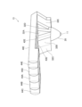
- FIG. 11 is a perspective view of a headlight device according to a second embodiment, as viewed from the right front.
- FIG. 11 is a perspective view of a headlamp device according to a second embodiment, as viewed from the lower left.
- FIG. 11 is a front view of a headlight device according to a second embodiment.
- FIG. 11 is a plan view of a headlight device according to a second embodiment.
- FIG. 11 is a bottom view of the headlight device according to the second embodiment.
- FIG. 11 is a left side view of a headlight device according to a second embodiment.
- FIG. 11 is a perspective view of a headlamp device according to a second embodiment, as viewed from the left rear.
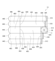
- FIG. 1 is a side view of a headlamp device according to embodiment 1.
- FIG. 2 is an enlarged view of a main portion of FIG. 1.
- the headlamp device according to embodiment 1 shown in FIG. 1 is mounted on a vehicle, for example.
- the headlamp device according to embodiment 1 is used in headlamp devices that illuminate the front of automobiles, motorcycles, and three-wheeled vehicles known as gyros (scooters and mopeds with three wheels, one in the front and two in the rear) that satisfy a predetermined light distribution pattern defined by road traffic regulations, etc.
- the headlamp device according to embodiment 1 has a low beam and a high beam.
- the headlight device according to embodiment 1 can be used for low beam and high beam, but is particularly suitable for use with low beam.
- the headlight device according to embodiment 1 is applied to a low beam headlight device for an automobile.
- the headlight device may be a single device, or multiple headlight devices may be arranged in parallel in the left-right direction.
- the low beam of the headlamp device according to the first embodiment has a characteristic light distribution called cut-off light distribution, which is designed not to dazzle the driver of an oncoming vehicle.
- the headlamp device according to the first embodiment also has a light distribution called overhead light distribution, which improves the recognition rate of signs, etc., by illuminating the area above the cut-off light distribution with a lighter brightness.
- the headlamp device includes a light source 11 and a lens body 12.
- the light source 11 irradiates light toward the entrance portion 20 of the lens body 12, which will be described later.
- the light source 11 has a rectangular exit surface that emits light to the front.
- the light source 11 is either a tube light source such as an incandescent light bulb, a halogen lamp, or a fluorescent lamp, or a semiconductor light source such as a light emitting diode (LED (Light Emitting Diode), hereinafter referred to as LED) or a laser diode (LD (Laser Diode), hereinafter referred to as LD).
- LED Light Emitting Diode
- LD Laser Diode
- a semiconductor light source for the light source 11 which has a higher light-emitting efficiency than a halogen lamp, is directional, and allows the optical system to be made smaller and lighter.
- the lens body 12 is formed from a transparent material whose interior is filled with a refractive material.
- the lens body 12 is manufactured, for example, by injection molding.
- the material from which the lens body 12 is formed is preferably one that is highly transparent from the standpoint of light utilization efficiency, and has excellent heat resistance, since the lens body 12 is disposed immediately after the light source 11.
- the material from which the lens body 12 is formed is preferably a transparent resin such as glass or silicone material.
- suitable transparent resins include acrylic resins (especially PMMA: polymethyl methacrylate), polycarbonate (PC), and cycloolefin resins.
- the lens body 12 has an incident portion 20, a light guide portion 30, and a light distribution forming portion 40.
- the incident portion 20, the light guide portion 30, and the light distribution forming portion 40 are formed integrally.
- the light guide portion 30 and the light distribution forming portion 40 are formed so as to intersect with each other.
- the incident portion 20 has a cone shape.
- the incident portion 20 has a lens 21 and a reflective surface 22.
- the lens 21 is provided inside the apex of the incident portion 20.
- the reflective surface 22 is formed by the inner peripheral surface of the incident portion 20.
- the light source 11 is provided outside the apex of the incident portion 20, in other words, at the front end of the incident portion 20.
- the light source 11 and the lens 21 face each other.
- the incident portion 20 allows the light emitted from the light source 11 to enter through the lens 21.
- Light emitted from light source 11 with a small emission angle is incident on lens 21 and then guided directly towards the cone-shaped bottom surface of incident section 20.
- light emitted from light source 11 with a large emission angle is incident on lens 21 and then reflected by reflective surface 22 and guided towards the cone-shaped bottom surface of incident section 20.
- the light directly guided from lens 21 and the light reflected and guided by reflective surface 22 are guided towards light-guiding section 30 as approximately parallel light.
- the front end (light source 11 side) of the light guiding unit 30 is connected to the input unit 20.
- the cross-sectional shape of the front end side of the light guiding unit 30 may be rectangular, circular, or elliptical.
- the projection surface 44 side (described later) on the front end side of the light guiding unit 30 may be a curved surface that is convex or concave.
- the rear end of the light guiding unit 30 is connected to the light distribution forming unit 40.
- the light guide section 30 is a long and narrow section that extends in a straight line from the entrance section 20 to the light distribution forming section 40.
- the light guide section 30 has a first light guide reflecting surface 31 and a second light guide reflecting surface 32.
- the first light guide reflecting surface 31 and the second light guide reflecting surface 32 face each other.
- the second light guide reflecting surface 32 may be a curved surface that is convex or concave with respect to the lens body 12.
- the second light guide reflecting surface 32 also serves as an exit surface for forming an overhead light distribution, as will be described in detail later.
- the light guide unit 30 guides the light incident from the entrance unit 20 directly toward the light distribution forming unit 40.
- the light guide unit 30 also reflects the light incident from the entrance unit 20 onto the first light guide reflecting surface 31, or onto the first light guide reflecting surface 31 and the second light guide reflecting surface 32, and then guides the light toward the light distribution forming unit 40.
- the front end of the light distribution forming section 40 is connected to the rear end of the light guiding section 30.
- the light distribution forming section 40 is a long and thin section that extends linearly in a direction perpendicular to the light guiding section 30.
- the light guiding section 30 and the light distribution forming section 40 do not necessarily need to be perpendicular to each other, but may be arranged so as to intersect. Specifically, the extension direction of the light guiding section 30 and the extension direction of the light distribution forming section 40 intersect so that the light emitted from the light source 11 is incident on the first light distribution reflecting surface 41.
- the first light distribution reflecting surface 41 is provided on the light guiding section 30 side of the light distribution forming section 40 so as to reflect the light emitted from the light source 11 and passing through the light guiding section 30.
- the first light distribution reflecting surface 41 is disposed at an angle with respect to the length direction of the light distribution forming section 40.
- the front end of the first light distribution reflecting surface 41 is connected to the rear end of the first light guiding reflecting surface 31 of the light guiding section 30 and is disposed so as to intersect with the first light guiding reflecting surface 31.
- the first light distributing reflecting surface 41 reflects light reflected by the first light guiding reflecting surface 31 and the second light guiding reflecting surface 32 of the light guiding section 30.
- the first light distributing reflecting surface 41 also reflects light that is not reflected by the first light guiding reflecting surface 31 and the second light guiding reflecting surface 32 of the light guiding section 30.
- the first light distributing reflecting surface 41 reflects a portion of the reflected light as a cutoff light distribution, and guides the light toward the second light distributing reflecting surface 42 and the projection surface 44 described below.
- the first light distributing reflecting surface 41 also reflects the rest of the reflected light as an overhead light distribution, and transmits it to the second light guiding reflecting surface 32, and guides it toward the projection surface 44 described below.
- the second light distribution reflecting surface 42 extends in the longitudinal direction of the light distribution forming section 40.
- the second light distribution reflecting surface 42 is arranged so as to be inclined with respect to the first light distribution reflecting surface 41.
- the front end of the second light distribution reflecting surface 42 is connected to the rear end of the second light guide reflecting surface 32 of the light guide section 30, and is arranged so as to intersect with the second light guide reflecting surface 32.
- the second light distribution reflecting surface 42 reflects a portion of the light reflected by the first light distribution reflecting surface 41 as a cutoff light distribution, and guides the light toward the projection surface 44 described below.
- the incident surface 43 is connected to the rear end of the second light distributing reflecting surface 42 and is arranged so as to intersect with the second light distributing reflecting surface 42.
- the incident surface 43 is arranged so as to face the second light guiding reflecting surface 32 of the light guiding section 30 on the outside of the lens body 12.
- the incident surface 43 and the second light guiding reflecting surface 32 may have any intersection angle with each other.
- the incident surface 43 may also be a curved surface that is convex or concave with respect to the lens body 12.
- the incident surface 43 allows the light that has been reflected by the first light distribution reflecting surface 41 as an overhead light distribution and then transmitted through the second light guide reflecting surface 32 to enter the interior of the lens body 12.
- the incident surface 43 also guides the incident light toward the projection surface 44, which will be described later.
- the incident surface 43 allows the light that has once exited the lens body 12 from the second light guide reflecting surface 32 as an overhead light distribution to enter the interior of the lens body 12 again.
- the projection surface 44 forms the rear end surface of the light distribution forming unit 40.
- the projection surface 44 is formed in a convex shape that bulges out toward the front of the light distribution forming unit 40.
- the projection surface 44 projects the light reflected by the first light distribution reflecting surface 41 toward the front of the light distribution forming unit 40 as a cut-off light distribution.
- the projection surface 44 projects the light reflected by the second light distribution reflecting surface 42 toward the front of the light distribution forming unit 40 as a cut-off light distribution.
- the projection surface 44 projects the light that is again incident inside the lens body 12 by the entrance surface 43 toward the front of the light distribution forming unit 40 as an overhead light distribution.
- Light R1 to R4 form a cutoff light distribution.
- Light R4 forms an overhead light distribution.
- Light R1 is incident on the entrance portion 20 from the light source 11, is reflected by the reflecting surface 22 of the entrance portion 20, and is then reflected by the first light distribution reflecting surface 41 and the second light distribution reflecting surface 42 of the light distribution forming portion 40. The light R1 is then guided toward the projection surface 44, and is projected forward from the projection surface 44.
- Light R2 is incident on the entrance portion 20 from the light source 11, is reflected by the reflecting surface 22 of the entrance portion 20, and is then reflected by the first light-guiding reflecting surface 31 of the light-guiding portion 30. The light R2 is then reflected by the first light-distributing reflecting surface 41 of the light distribution forming portion 40. The light R2 is not reflected by the second light-distributing reflecting surface 42. The light R2 is then guided towards the projection surface 44, and is projected forward from the projection surface 44.
- Light R3 is incident on the entrance portion 20 from the light source 11, is reflected by the reflecting surface 22 of the entrance portion 20, and is then reflected by the second light-guiding reflecting surface 32 of the light-guiding portion 30.
- the light R3 is then reflected by the first light-distributing reflecting surface 41 of the light distribution forming portion 40.
- the light R3 is not reflected by the second light-distributing reflecting surface 42.
- the light R3 is then guided towards the projection surface 44, and is projected forward from the projection surface 44.
- Light R4 is incident on the entrance portion 20 from the light source 11, is reflected by the reflecting surface 22 of the entrance portion 20, and is then reflected by the first light distribution reflecting surface 41 of the light distribution forming portion 40.
- the light R4 then passes through the second light guide reflecting surface 32, which also serves as the exit surface to the outside of the lens body 12, and is once emitted toward the outside of the lens body 12, before being incident again from the entrance surface 43 of the light distribution forming portion 40 toward the inside of the lens body 12.
- the light R4 is then guided toward the projection surface 44, and is projected forward from the projection surface 44.
- the headlamp device according to embodiment 1 does not require a dedicated exit surface for forming the overhead light distribution by transmitting the light R4 that forms the overhead light distribution through the second light-guiding reflecting surface 32, which also serves as the exit surface to the outside of the lens body 12. Therefore, the headlamp device according to embodiment 1 can simplify the configuration of the lens body 12.
- the headlamp device according to embodiment 1 can form an overhead light distribution without providing the lens body 12 with a dedicated exit surface for forming the overhead light distribution.
- Embodiment 2 A headlamp device according to the second embodiment will be described with reference to Fig. 3 to Fig. 9. Components having the same functions as those described in the first embodiment will be denoted by the same reference numerals, and description thereof will be omitted.
- Figure 3 is a perspective view of the headlight device according to embodiment 2 as seen from the front right.
- Figure 4 is a perspective view of the headlight device according to embodiment 2 as seen from the lower left.
- Figure 5 is a front view of the headlight device according to embodiment 2.
- Figure 6 is a plan view of the headlight device according to embodiment 2.
- Figure 7 is a bottom view of the headlight device according to embodiment 2.
- Figure 8 is a left side view of the headlight device according to embodiment 2.
- Figure 9 is a perspective view of the headlight device according to embodiment 2 as seen from the rear left.
- the headlamp device according to embodiment 2 includes a light source 11 and a lens body 13.
- the lens body 13 has one entrance section 20, five light guiding sections 30A-30E, and five light distribution forming sections 40A-40E.
- the number of light guiding sections is the same as the number of light distribution forming sections.
- the lens body 13 has one entrance section 20, multiple light guiding sections 30A-30E, and multiple light distribution forming sections 40A-40E corresponding to each of the multiple light guiding sections 30A-30E.
- the entrance section 20, light guiding sections 30A-30E, and light distribution forming sections 40A-40E are formed integrally.
- the entrance section 20 is common to all light paths.
- the light guiding sections 30A-30E are formed to branch off from the entrance section 20.
- the incident section 20, the light guide section 30A, and the light distribution forming section 40A correspond to each other and form a first optical path.
- the incident section 20, the light guide section 30B, and the light distribution forming section 40B correspond to each other and form a second optical path.
- the incident section 20, the light guide section 30C, and the light distribution forming section 40C correspond to each other and form a third optical path.
- the incident section 20, the light guide section 30D, and the light distribution forming section 40D correspond to each other and form a fourth optical path.
- the incident section 20, the light guide section 30E, and the light distribution forming section 40E correspond to each other and form a fifth optical path. Each of these optical paths allows the light R1 to R4 described in the first embodiment to pass through.
- the side on which the light guide 30C and the light distribution forming unit 40C are arranged is the right side when viewed from the front on which the light source 11 is arranged.
- the side on which the light guide 30E and the light distribution forming unit 40E are arranged is the left side when viewed from the front on which the light source 11 is arranged.
- the five light paths are arranged side by side in the left-right direction (width direction) of the headlight device.
- the light guide section 30A has a first light guide reflecting surface 31A and a second light guide reflecting surface 32A.
- the second light guide reflecting surface 32A also serves as an exit surface for forming an overhead light distribution.
- the light guide unit 30A guides the light incident from the entrance unit 20 directly toward the light distribution forming unit 40A.
- the light guide unit 30A also reflects the light incident from the entrance unit 20 onto the first light guide reflecting surface 31A, or onto the first light guide reflecting surface 31A and the second light guide reflecting surface 32A, and then guides the light toward the light distribution forming unit 40A.
- the light distribution forming section 40A has a first light distribution reflecting surface 41A, a second light distribution reflecting surface 42A, an incident surface 43A, and a projection surface 44A.
- the first light distribution reflecting surface 41A reflects the light reflected by the first light guide reflecting surface 31A and the second light guide reflecting surface 32A of the light guide section 30A.
- the first light distribution reflecting surface 41A also reflects the light that is not reflected by the first light guide reflecting surface 31A and the second light guide reflecting surface 32A of the light guide section 30A.
- the first light distribution reflecting surface 41A reflects a portion of the reflected light as a cutoff light distribution, and guides the light toward the second light distribution reflecting surface 42A and the projection surface 44A described below.
- the first light distribution reflecting surface 41A also reflects the rest of the reflected light as an overhead light distribution, and transmits it to the second light guide reflecting surface 32A, and guides it toward the projection surface 44A described below.
- the second light distribution reflecting surface 42A reflects a portion of the light reflected by the first light distribution reflecting surface 41A as a cutoff light distribution, and guides the light toward the projection surface 44A, which will be described later.
- the incident surface 43A allows the light that has been reflected by the first light distribution reflecting surface 41A as an overhead light distribution and then transmitted through the second light guide reflecting surface 32A to enter the interior of the lens body 13.
- the incident surface 43A also guides the incident light toward the projection surface 44A, which will be described later.
- the incident surface 43A allows the light that has once exited the lens body 13 from the second light guide reflecting surface 32A as an overhead light distribution to enter the interior of the lens body 13 again.
- the projection surface 44A projects the light reflected by the first light distribution reflecting surface 41A toward the front of the light distribution forming unit 40A as a cut-off light distribution.
- the projection surface 44A projects the light reflected by the second light distribution reflecting surface 42A toward the front of the light distribution forming unit 40A as a cut-off light distribution.
- the projection surface 44A projects the light that is again incident inside the lens body 13 by the entrance surface 43A toward the front of the light distribution forming unit 40A as an overhead light distribution.
- the light-guiding section 30B has a first light-guiding reflecting surface 31B and a second light-guiding reflecting surface 32B.
- the second light-guiding reflecting surface 32B also serves as an exit surface for forming an overhead light distribution.
- the light guide section 30B guides the light incident from the entrance section 20 directly toward the light distribution forming section 40B.
- the light guide section 30B also reflects the light incident from the entrance section 20 onto the first light guide reflecting surface 31B, or onto the first light guide reflecting surface 31B and the second light guide reflecting surface 32B, and then guides the light toward the light distribution forming section 40B.
- the light distribution forming portion 40B has a first light distribution reflecting surface 41B, a second light distribution reflecting surface 42B, an incident surface 43B, and a projection surface 44B.
- the first light distributing reflecting surface 41B reflects the light reflected by the first light guiding reflecting surface 31B and the second light guiding reflecting surface 32B of the light guiding section 30B.
- the first light distributing reflecting surface 41B also reflects the light that is not reflected by the first light guiding reflecting surface 31B and the second light guiding reflecting surface 32B of the light guiding section 30B.
- the first light distributing reflecting surface 41B reflects a portion of the reflected light as a cutoff light distribution, and guides the light toward the second light distributing reflecting surface 42B and the projection surface 44B described below.
- the first light distributing reflecting surface 41B also reflects the rest of the reflected light as an overhead light distribution, and transmits it to the second light guiding reflecting surface 32B, and guides it toward the projection surface 44B described below.
- the second light distribution reflecting surface 42B reflects a portion of the light reflected by the first light distribution reflecting surface 41B as a cutoff light distribution, and guides the light toward the projection surface 44B described below.
- the incident surface 43B allows the light that has been reflected by the first light distribution reflecting surface 41B as an overhead light distribution and then transmitted through the second light guide reflecting surface 32B to enter the interior of the lens body 13.
- the incident surface 43B also guides the incident light toward the projection surface 44B, which will be described later.
- the incident surface 43B allows the light that has once exited the lens body 13 from the second light guide reflecting surface 32B as an overhead light distribution to enter the interior of the lens body 13 again.
- the projection surface 44B projects the light reflected by the first light distribution reflecting surface 41B toward the front of the light distribution forming unit 40B as a cut-off light distribution.
- the projection surface 44B projects the light reflected by the second light distribution reflecting surface 42B toward the front of the light distribution forming unit 40B as a cut-off light distribution.
- the projection surface 44B projects the light that is again incident inside the lens body 13 by the entrance surface 43B toward the front of the light distribution forming unit 40B as an overhead light distribution.
- the light-guiding unit 30C has a first light-guiding reflecting surface 31C and a second light-guiding reflecting surface 32C.
- the second light-guiding reflecting surface 32C also serves as an emission surface for forming an overhead light distribution.
- the second light-guiding reflecting surface 32B of the light-guiding unit 30B and the second light-guiding reflecting surface 32C of the light-guiding unit 30C are the same surface.
- the light guide section 30C guides the light incident from the entrance section 20 directly toward the light distribution forming section 40C.
- the light guide section 30C also reflects the light incident from the entrance section 20 onto the first light guide reflecting surface 31C, or onto the first light guide reflecting surface 31C and the second light guide reflecting surface 32C, and then guides the light toward the light distribution forming section 40C.
- the light distribution forming portion 40C has a first light distribution reflecting surface 41C, a second light distribution reflecting surface 42C, an incident surface 43C, and a projection surface 44C.
- the first light distributing reflecting surface 41C reflects the light reflected by the first light guiding reflecting surface 31C and the second light guiding reflecting surface 32C of the light guiding section 30C.
- the first light distributing reflecting surface 41C also reflects the light that is not reflected by the first light guiding reflecting surface 31C and the second light guiding reflecting surface 32C of the light guiding section 30C.
- the first light distributing reflecting surface 41C reflects a portion of the reflected light as a cutoff light distribution, and guides the light toward the second light distributing reflecting surface 42C and the projection surface 44C described below.
- the first light distributing reflecting surface 41C also reflects the rest of the reflected light as an overhead light distribution, and transmits it to the second light guiding reflecting surface 32C, and guides it toward the projection surface 44C described below.
- the second light distribution reflecting surface 42C reflects a portion of the light reflected by the first light distribution reflecting surface 41C as a cutoff light distribution, and guides the light toward the projection surface 44C described below.
- the incident surface 43C allows the light that has been reflected by the first light distribution reflecting surface 41C as an overhead light distribution and then transmitted through the second light guide reflecting surface 32C to enter the interior of the lens body 13.
- the incident surface 43C also guides the incident light toward the projection surface 44C, which will be described later.
- the incident surface 43C allows the light that has once exited the lens body 13 from the second light guide reflecting surface 32C as an overhead light distribution to enter the interior of the lens body 13 again.
- the projection surface 44C projects the light reflected by the first light distribution reflecting surface 41C toward the front of the light distribution forming unit 40C as a cut-off light distribution.
- the projection surface 44C projects the light reflected by the second light distribution reflecting surface 42C toward the front of the light distribution forming unit 40C as a cut-off light distribution.
- the projection surface 44C projects the light that is again incident inside the lens body 13 by the entrance surface 43C toward the front of the light distribution forming unit 40C as an overhead light distribution.
- the light-guiding section 30D has a first light-guiding reflecting surface 31D and a second light-guiding reflecting surface 32D.
- the second light-guiding reflecting surface 32D also serves as an exit surface for forming an overhead light distribution.
- the light guide section 30D guides the light incident from the entrance section 20 directly toward the light distribution forming section 40D.
- the light guide section 30D also reflects the light incident from the entrance section 20 onto the first light guide reflecting surface 31D, or onto the first light guide reflecting surface 31D and the second light guide reflecting surface 32D, and then guides the light toward the light distribution forming section 40D.
- the light distribution forming section 40D has a first light distribution reflecting surface 41D, a second light distribution reflecting surface 42D, an entrance surface 43D, and a projection surface 44D.
- the first light distributing reflecting surface 41D reflects the light reflected by the first light guiding reflecting surface 31D and the second light guiding reflecting surface 32D of the light guiding unit 30D.
- the first light distributing reflecting surface 41D also reflects the light that is not reflected by the first light guiding reflecting surface 31D and the second light guiding reflecting surface 32D of the light guiding unit 30D.
- the first light distributing reflecting surface 41D reflects a portion of the reflected light as a cutoff light distribution, and guides the light toward the second light distributing reflecting surface 42D and the projection surface 44D described below.
- the first light distributing reflecting surface 41D also reflects the rest of the reflected light as an overhead light distribution, and transmits it to the second light guiding reflecting surface 32D, and guides it toward the projection surface 44D described below.
- the incident surface 43D allows the light that has been reflected by the first light distribution reflecting surface 41D as an overhead light distribution and then transmitted through the second light guide reflecting surface 32D to enter the interior of the lens body 13.
- the incident surface 43D also guides the incident light toward the incident surface 43D, which will be described later.
- the incident surface 43D allows the light that has once exited the lens body 13 from the second light guide reflecting surface 32D as an overhead light distribution to enter the interior of the lens body 13 again.
- the projection surface 44D projects the light reflected by the first light distribution reflecting surface 41D toward the front of the light distribution forming unit 40D as a cut-off light distribution.
- the projection surface 44D projects the light reflected by the second light distribution reflecting surface 42D toward the front of the light distribution forming unit 40D as a cut-off light distribution.
- the projection surface 44D projects the light that is again incident inside the lens body 13 by the entrance surface 43D toward the front of the light distribution forming unit 40D as an overhead light distribution.
- the light-guiding unit 30E has a first light-guiding reflecting surface 31E and a second light-guiding reflecting surface 32E.
- the second light-guiding reflecting surface 32E also serves as an exit surface for forming an overhead light distribution.
- the first light-guiding reflecting surface 31D of the light-guiding unit 30D and the first light-guiding reflecting surface 31E of the light-guiding unit 30E are the same surface.
- the light guide unit 30E guides the light incident from the entrance unit 20 directly toward the light distribution forming unit 40E.
- the light guide unit 30E also reflects the light incident from the entrance unit 20 onto the first light guide reflecting surface 31E, or onto the first light guide reflecting surface 31E and the second light guide reflecting surface 32E, and then guides the light toward the light distribution forming unit 40E.
- the light distribution forming portion 40E has a first light distribution reflecting surface 41E, a second light distribution reflecting surface 42E, an incident surface 43E, and a projection surface 44E.
- the first light distributing reflecting surface 41E reflects the light reflected by the first light guiding reflecting surface 31E and the second light guiding reflecting surface 32E of the light guiding unit 30E.
- the first light distributing reflecting surface 41E also reflects the light that is not reflected by the first light guiding reflecting surface 31E and the second light guiding reflecting surface 32E of the light guiding unit 30E.
- the first light distributing reflecting surface 41E reflects a portion of the reflected light as a cutoff light distribution, and guides the light toward the second light distributing reflecting surface 42E and the projection surface 44E described below.
- the first light distributing reflecting surface 41E also reflects the rest of the reflected light as an overhead light distribution, and transmits it to the second light guiding reflecting surface 32E, and guides it toward the projection surface 44E described below.
- the second light distribution reflecting surface 42E reflects a portion of the light reflected by the first light distribution reflecting surface 41E as a cutoff light distribution, and guides the light toward the projection surface 44E, which will be described later.
- the incident surface 43E allows the light that has been reflected by the first light distribution reflecting surface 41E as an overhead light distribution and then transmitted through the second light guide reflecting surface 32E to enter the interior of the lens body 13.
- the incident surface 43E also guides the incident light toward the projection surface 44E, which will be described later.
- the incident surface 43E allows the light that has once exited the lens body 13 from the second light guide reflecting surface 32E as an overhead light distribution to enter the interior of the lens body 13 again.
- the projection surface 44E projects the light reflected by the first light distribution reflecting surface 41E toward the front of the light distribution forming unit 40E as a cut-off light distribution.
- the projection surface 44E projects the light reflected by the second light distribution reflecting surface 42E toward the front of the light distribution forming unit 40E as a cut-off light distribution.
- the projection surface 44E projects the light that is again incident inside the lens body 13 by the entrance surface 43E toward the front of the light distribution forming unit 40E as an overhead light distribution.
- the headlamp device according to embodiment 2 does not require a dedicated exit surface for forming the overhead light distribution by transmitting the light that forms the overhead light distribution (corresponding to R4 according to embodiment 1) through the second light-guiding reflecting surfaces 32A-32E, which also serve as the exit surface to the outside of the lens body 13. Therefore, the headlamp device according to embodiment 2 can simplify the configuration of the lens body 13.
- the headlight device according to the second embodiment can have any number of light guiding sections and light distribution forming sections, as long as the headlight device is configured to guide light from two or more (multiple) adjacent light distribution forming sections to the projection surface.
- the headlamp device according to embodiment 2 can form an overhead light distribution without providing the lens body 13 with a dedicated exit surface for forming the overhead light distribution.
- the headlamp device according to the present disclosure is suitable for use in headlamp devices, etc., because the second light-guiding reflective surface also serves as the exit surface to the outside of the lens body, and thus can form an overhead light distribution without providing the lens body with a dedicated exit surface for forming the overhead light distribution.
Landscapes
- Engineering & Computer Science (AREA)
- General Engineering & Computer Science (AREA)
- Physics & Mathematics (AREA)
- Microelectronics & Electronic Packaging (AREA)
- Optics & Photonics (AREA)
- Non-Portable Lighting Devices Or Systems Thereof (AREA)
Priority Applications (2)
| Application Number | Priority Date | Filing Date | Title |
|---|---|---|---|
| JP2025545355A JPWO2025057318A1 (https=) | 2023-09-13 | 2023-09-13 | |
| PCT/JP2023/033276 WO2025057318A1 (ja) | 2023-09-13 | 2023-09-13 | 前照灯装置 |
Applications Claiming Priority (1)
| Application Number | Priority Date | Filing Date | Title |
|---|---|---|---|
| PCT/JP2023/033276 WO2025057318A1 (ja) | 2023-09-13 | 2023-09-13 | 前照灯装置 |
Publications (1)
| Publication Number | Publication Date |
|---|---|
| WO2025057318A1 true WO2025057318A1 (ja) | 2025-03-20 |
Family
ID=95021063
Family Applications (1)
| Application Number | Title | Priority Date | Filing Date |
|---|---|---|---|
| PCT/JP2023/033276 Pending WO2025057318A1 (ja) | 2023-09-13 | 2023-09-13 | 前照灯装置 |
Country Status (2)
| Country | Link |
|---|---|
| JP (1) | JPWO2025057318A1 (https=) |
| WO (1) | WO2025057318A1 (https=) |
Citations (5)
| Publication number | Priority date | Publication date | Assignee | Title |
|---|---|---|---|---|
| JP2017084556A (ja) * | 2015-10-27 | 2017-05-18 | スタンレー電気株式会社 | レンズ体、レンズ結合体及び車両用灯具 |
| JP2021072254A (ja) * | 2019-11-01 | 2021-05-06 | 市光工業株式会社 | 車両用導光体及び車両用前照灯 |
| JP2021086724A (ja) * | 2019-11-27 | 2021-06-03 | 市光工業株式会社 | 車両用導光体及び車両用灯具ユニット |
| JP2022515178A (ja) * | 2018-12-21 | 2022-02-17 | ツェットカーヴェー グループ ゲーエムベーハー | 自動車前照灯用照明装置及び自動車前照灯 |
| JP2022521932A (ja) * | 2019-02-25 | 2022-04-13 | ▲華▼域▲視▼▲覺▼科技(上▲海▼)有限公司 | ハイ・ロービームランプ一体型車ランプ照明装置、車ランプ及び車両 |
-
2023
- 2023-09-13 JP JP2025545355A patent/JPWO2025057318A1/ja active Pending
- 2023-09-13 WO PCT/JP2023/033276 patent/WO2025057318A1/ja active Pending
Patent Citations (5)
| Publication number | Priority date | Publication date | Assignee | Title |
|---|---|---|---|---|
| JP2017084556A (ja) * | 2015-10-27 | 2017-05-18 | スタンレー電気株式会社 | レンズ体、レンズ結合体及び車両用灯具 |
| JP2022515178A (ja) * | 2018-12-21 | 2022-02-17 | ツェットカーヴェー グループ ゲーエムベーハー | 自動車前照灯用照明装置及び自動車前照灯 |
| JP2022521932A (ja) * | 2019-02-25 | 2022-04-13 | ▲華▼域▲視▼▲覺▼科技(上▲海▼)有限公司 | ハイ・ロービームランプ一体型車ランプ照明装置、車ランプ及び車両 |
| JP2021072254A (ja) * | 2019-11-01 | 2021-05-06 | 市光工業株式会社 | 車両用導光体及び車両用前照灯 |
| JP2021086724A (ja) * | 2019-11-27 | 2021-06-03 | 市光工業株式会社 | 車両用導光体及び車両用灯具ユニット |
Also Published As
| Publication number | Publication date |
|---|---|
| JPWO2025057318A1 (https=) | 2025-03-20 |
Similar Documents
| Publication | Publication Date | Title |
|---|---|---|
| JP5664900B2 (ja) | 車両用光学ユニット | |
| JP5945857B2 (ja) | 車両用前照灯及び導光レンズ | |
| JP7081977B2 (ja) | 車両用灯具 | |
| JP7211903B2 (ja) | 車両用灯具 | |
| JP5374140B2 (ja) | 車輌用灯具 | |
| JP6777432B2 (ja) | 車両用灯具 | |
| JP7675673B2 (ja) | 前照灯装置用光源分配素子、前照灯装置、及び前照灯モジュール | |
| JP7675890B2 (ja) | 車両用の前照灯 | |
| CN106461179A (zh) | 车辆用导光部件、车辆用灯具 | |
| JP7079654B2 (ja) | 車両用灯具 | |
| JP6737644B2 (ja) | 車両用灯具 | |
| JP6933901B2 (ja) | 車両用灯具 | |
| JP7440315B2 (ja) | 車両用灯具 | |
| JP6539484B2 (ja) | 車両用導光体、車両用灯具 | |
| CN210219614U (zh) | 车辆用灯具 | |
| WO2025057318A1 (ja) | 前照灯装置 | |
| JP2022069185A (ja) | 車両用灯具 | |
| JP7828215B2 (ja) | 車両用灯具 | |
| JP7277004B2 (ja) | 車両用灯具 | |
| WO2023210343A1 (ja) | 車両用灯具 | |
| JP7554101B2 (ja) | 車両用灯具 | |
| JP2022162292A (ja) | 車両用灯具 | |
| JP7702370B2 (ja) | 車両用灯具 | |
| CN218295568U (zh) | 用于车辆的灯和车辆 | |
| KR102931017B1 (ko) | 차량용 램프 |
Legal Events
| Date | Code | Title | Description |
|---|---|---|---|
| 121 | Ep: the epo has been informed by wipo that ep was designated in this application |
Ref document number: 23952212 Country of ref document: EP Kind code of ref document: A1 |
|
| ENP | Entry into the national phase |
Ref document number: 2025545355 Country of ref document: JP Kind code of ref document: A |