WO2025052814A1 - モータステータ及びモータ - Google Patents
モータステータ及びモータ Download PDFInfo
- Publication number
- WO2025052814A1 WO2025052814A1 PCT/JP2024/027131 JP2024027131W WO2025052814A1 WO 2025052814 A1 WO2025052814 A1 WO 2025052814A1 JP 2024027131 W JP2024027131 W JP 2024027131W WO 2025052814 A1 WO2025052814 A1 WO 2025052814A1
- Authority
- WO
- WIPO (PCT)
- Prior art keywords
- core sheet
- core
- sheet layer
- motor stator
- offset
- Prior art date
- Legal status (The legal status is an assumption and is not a legal conclusion. Google has not performed a legal analysis and makes no representation as to the accuracy of the status listed.)
- Pending
Links
Images



Classifications
-
- H—ELECTRICITY
- H02—GENERATION; CONVERSION OR DISTRIBUTION OF ELECTRIC POWER
- H02K—DYNAMO-ELECTRIC MACHINES
- H02K1/00—Details of the magnetic circuit
- H02K1/06—Details of the magnetic circuit characterised by the shape, form or construction
- H02K1/12—Stationary parts of the magnetic circuit
- H02K1/16—Stator cores with slots for windings
-
- H—ELECTRICITY
- H02—GENERATION; CONVERSION OR DISTRIBUTION OF ELECTRIC POWER
- H02K—DYNAMO-ELECTRIC MACHINES
- H02K1/00—Details of the magnetic circuit
- H02K1/06—Details of the magnetic circuit characterised by the shape, form or construction
- H02K1/12—Stationary parts of the magnetic circuit
- H02K1/18—Means for mounting or fastening magnetic stationary parts on to, or to, the stator structures
Definitions
- the present invention relates to a motor stator and a motor.
- Patent Document 1 discloses a stator core (motor stator) that has a first core sheet located at both ends, and a second core sheet that is provided between the first core sheets and has an arc-shaped groove that forms a recess at the end on the inner circumferential surface side, and is bonded and fixed with an adhesive applied to the recess.
- the present invention was made in consideration of the above problems, and aims to improve the joining strength of motor cores.
- the laminated core comprises a plurality of first core sheet layers, a plurality of second core sheet layers that are alternately laminated with the first core sheet layers, and an adhesive that bonds the first core sheet layers to the second core sheet layers, and each of the first core sheet layers has an offset portion that does not overlap with the second core sheet layer in the axial direction, and the adhesive bonds the offset portions that face each other in the axial direction.
- a first core sheet layer having an offset portion and a second core sheet layer whose offset portions do not overlap in the axial direction are alternately stacked, and the offset portions of the first core sheet layers are bonded together with an adhesive. Therefore, since the offset portions of the first core sheet layers that are alternately stacked with the second core sheet layers are bonded together with an adhesive, the area bonded by the adhesive can be increased. This can improve the joining strength of the motor core.
- FIG. 1 is a diagram showing the configuration of a motor to which an embodiment of the present invention can be applied.
- FIG. 2 is an enlarged view of a main portion of a first core sheet in the laminated core of the motor stator according to the first embodiment of the present invention.
- FIG. 3 is an enlarged view of a main portion of a second core sheet in the laminated core of the motor stator according to the first embodiment of the present invention.
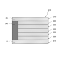
- FIG. 4 is a cross-sectional view of a side surface of a laminated core in the motor stator according to the first embodiment of the present invention.
- FIG. 5 is a configuration diagram showing a comparative example to FIG.
- FIG. 6 is an enlarged view of a main portion of a second core sheet in a laminated core of a motor stator according to a second embodiment of the present invention.
- FIG. 1 is a configuration diagram of the motor 100.
- the motor 100 includes a stator 1 serving as a motor stator and a rotor 2.
- the direction of the central axis of the stator 1 will be referred to as the "axial direction”
- the direction of rotation of the rotor 2 in the stator 1 will be referred to as the “circumferential direction”
- the direction extending radially from the central axis of the stator 1 will be referred to as the "radial direction”.
- the stator 1 is the stator of the motor 100 and is formed in a generally cylindrical shape.
- the stator 1 has a laminated core 10 and a winding (not shown).
- the laminated core 10 will be described in detail later with reference to Figures 2 to 6.
- the rotor 2 is the rotor of the motor 100 and is formed in a roughly cylindrical shape extending in the axial direction.
- the rotor 2 is installed at the center of the stator 1.
- Figure 2 is an enlarged view of a main portion of the first core sheet 20a in the laminated core 10.
- Figure 3 is an enlarged view of a main portion of the second core sheet 30a in the laminated core 10.
- Figure 4 is a cross-sectional view of the side of the laminated core 10 in the stator 1.
- the laminated core 10 comprises a plurality of first core sheet layers 20, a plurality of second core sheet layers 30, an adhesive 40, and a weld 50.
- the first core sheet layer 20 has a single first core sheet 20a.
- the first core sheet layer 20 may have multiple first core sheets 20a. That is, the first core sheet layer 20 has a single or multiple first core sheets 20a.
- the first core sheet 20a is a thin sheet of electromagnetic steel formed into a substantially circular shape.
- the first core sheet 20a constitutes a cylindrical laminated core 10 extending in the axial direction, with the first core sheet layers 20 and the second core sheet layers 30 alternately stacked.
- the first core sheet 20a has a first annular portion 21 as an annular portion, a first extension portion 22 as an extension portion, a first remaining portion 23 as a remaining portion, a first teeth portion 24 as a teeth portion, and an offset portion 25.
- the first annular portion 21 is formed in a substantially circular shape centered on the central axis of the stator 1.
- the first extension portion 22 extends from the first annular portion 21 toward the radially inner periphery.
- the first extension portion 22 is provided at equal intervals in the circumferential direction. A winding is wound around the first extension portion 22.
- the first remaining portion 23 is a part of the first extending portion 22 that extends radially inward from the first annular portion 21.
- the first remaining portion 23 is the portion of the first extending portion 22 excluding the offset portion 25 described below.
- the first teeth portion 24 is formed in a generally T-shape.
- the first teeth portion 24 protrudes radially inward from the first extension portion 22.
- the first teeth portion 24 is formed to have a circumferential length greater than that of the first remaining portion 23.
- the offset portion 25 is a protrusion that protrudes from the first extension portion 22 on both circumferential sides.
- the offset portion 25 has a smaller radial length than the first remaining portion 23 of the first extension portion 22.
- the offset portion 25 is provided at a position closer to the first teeth portion 24 than to the first annular portion 21.
- the offset portion 25 is provided on the inner periphery than the radial center of the first extension portion 22.
- the offset portion 25 is formed radially inner than the first remaining portion 23.
- the offset portion 25 is provided aligned radially with the first teeth portion 24.
- the first core sheet 20a is formed in the following order from the radial outside: the first annular portion 21, the first remaining portion 23, the offset portion 25, and the first teeth portion 24.
- the first remaining portion 23 and the offset portion 25 together form the first extension portion 22.
- the amount of the first remaining portion 23 in the first extension portion 22 can be increased compared to when the offset portion 25 is provided over the entire radial length of the first extension portion 22. Therefore, the joining strength of the laminated core 10 can be improved without reducing the area of the electromagnetic steel sheets of the laminated core 10.
- the second core sheet 30a is a thin sheet of electromagnetic steel formed into a substantially circular shape.
- the second core sheet 30a constitutes a cylindrical laminated core 10 extending in the axial direction, with the first core sheet layers 20 and the second core sheet layers 30 being alternately stacked.
- the second core sheet 30a has a second annular portion 31 as an annular portion, a second extension portion 32 as an extension portion, and a second teeth portion 34 as a teeth portion.
- the second extension portion 32 extends from the second annular portion 31 toward the radially inner periphery.
- the second extension portions 32 are provided at equal intervals in the circumferential direction.
- the second extension portions 32 overlap in the axial direction with the first extension portion 22 of the first core sheet 20a and the second extension portion 32 of the other second core sheet 30a.
- the second extension portion 32 is wound with the windings stacked with the first extension portion 22.
- the second teeth portion 34 is generally T-shaped and protrudes radially inward from the second extension portion 32.
- the second teeth portion 34 overlaps in the axial direction with the first teeth portion 24 of the first core sheet 20a and the second teeth portion 34 of the other second core sheet 30a.
- the second core sheet layer 30 is alternately stacked with the first core sheet layer 20.
- the offset portions 25 provided on the first core sheet 20a protrude from the first extension portion 22 on both sides in the circumferential direction. Therefore, even when the first core sheet layer 20 and the second core sheet layer 30 are alternately stacked, the offset portions 25 do not overlap with the second core sheet layer 30.
- the first core sheet layers 20 and the second core sheet layers 30 are alternately stacked, the first core sheet layers 20 having the offset portions 25 face each other in the axial direction with the second core sheet layer 30 sandwiched between them.
- adhesive 40 bonds the first core sheet layer 20 and the second core sheet layer 30. Specifically, adhesive 40 is applied to the gap formed between the offset portion 25 and the second core sheet layer 30. By applying adhesive 40 to the gap of the offset portion 25, the offset portions 25 that face each other in the axial direction are bonded to each other. In addition, adhesive 40 further bonds the surface of the second core sheet layer 30 on the cross direction side that intersects with the axial direction.
- the welded portion 50 joins the outer periphery of the laminated core 10 by welding. This joins the outer periphery of the laminated core 10.
- the laminated core 10 is joined on both the inner and outer periphery sides. This further improves the joining strength of the laminated core 10. Note that the welded portion 50 does not need to be provided if sufficient joining strength can be ensured with the adhesive 40 alone.
- FIG. 5 is a cross-sectional side view of a laminated core 210 according to a comparative example.
- the laminated core 210 includes a pair of first core sheet layers 220, a plurality of second core sheet layers 230 provided between the pair of first core sheet layers 220, and an adhesive 240.
- the first core sheet layer 220 has a similar configuration to the first core sheet layer 20 of this embodiment
- the second core sheet layer 230 has a similar configuration to the second core sheet layer 30 of this embodiment.
- the adhesive 240 bonds the axially opposing surfaces of each offset portion 25 in the pair of first core sheet layers 220 to the surfaces of the second core sheet layers 230 in the cross direction that faces the axial direction.
- the offset portions 25 are provided only in the pair of first core sheet layers 220, the area bonded in the axial direction by the adhesive 240 is small. This may result in a reduced bonding strength of the laminated core 210.
- a first core sheet layer 20 having an offset portion 25 and a second core sheet layer 30 whose offset portions 25 do not overlap in the axial direction are alternately laminated, and the offset portions 25 of the first core sheet layer 20 are bonded together by an adhesive 40.
- the offset portions 25 of the first core sheet layer 20, which are alternately laminated with the second core sheet layer 30, are bonded together by the adhesive 40, and the area bonded by the adhesive 40 can be increased. Therefore, the bonding strength of the laminated core 10 can be improved.
- the offset portion 25 is provided radially inward relative to the first remaining portion 23. This allows the adhesive 40 to bond the laminated core 10 on the radially inner side. This makes it possible to prevent the radially inner side of the laminated core 10 from peeling off. This makes it possible to prevent peeling on the radially inner side of the laminated core 10, which would otherwise cause a decrease in the insertability of the winding.
- the offset portions 25 are formed so as to protrude from the first extension portion 22 on both sides in the circumferential direction, the radially inner side of the laminated core 10 can be joined without reducing the area of the electromagnetic steel sheets in the first core sheet layer 20. This makes it possible to improve the joining strength of the laminated core 10 without reducing the performance of the motor 100. Also, because the offset portions 25 protrude from the first extension portion 22 on both sides in the circumferential direction, the area of the electromagnetic steel sheets in the laminated core 10 can be increased, making it possible to generate a stronger magnetic force.
- a laminated core 110 according to a second embodiment will be described mainly with reference to Fig. 6.
- Fig. 6 is an enlarged view of a main portion of a second core sheet 130a in the laminated core 110.
- differences from the first embodiment will be mainly described, and components having the same functions as those in the first embodiment will be denoted by the same reference numerals and will not be described.
- the laminated core 110 comprises a plurality of first core sheet layers 120, a plurality of second core sheet layers 130, an adhesive 40, and a weld 50.
- the first core sheet layer 120 has a single first core sheet 120a.
- the first core sheet layer 120 may have a plurality of first core sheets 120a. That is, the first core sheet layer 120 has a first core sheet 120a.
- the first core sheet layer 120 has the same configuration as the second core sheet layer 130 in the first embodiment.
- the first core sheet 120a is a thin sheet of electromagnetic steel formed into a substantially circular shape.
- the first core sheet 120a has a first annular portion 21 as an annular portion, a first extension portion 22 as an extension portion, a first teeth portion 24 as a teeth portion, and an offset portion 125.
- the offset portion 125 is a portion that overlaps with a notch portion 136 provided in the second core sheet 130a described below when the first core sheet layer 120 and the second core sheet layer 130 are alternately stacked.
- the offset portion 125 is a part of the first extension portion 22. From the radial outside, the first core sheet 120a is formed in the following order: the first annular portion 21, the first extension portion 22, and the first teeth portion 24.
- the first extension portion 22 includes the offset portion 125.
- the second core sheet layer 130 has a single second core sheet 130a.
- the second core sheet layer 130 may have multiple second core sheets 30a. That is, the second core sheet layer 130 has a single or multiple second core sheets 130a.
- the second core sheet 130a is a thin sheet of electromagnetic steel formed into a substantially circular shape.
- the second core sheet 130a has a second annular portion 31 as an annular portion, a second extension portion 132 as an extension portion, a second teeth portion 34 as a teeth portion, and a notch portion 136.
- the notch portions 136 are notches formed on both circumferential sides of the second extending portion 132.
- the notch portions 136 have a smaller radial length than the second remaining portion 133 of the second extending portion 132.
- the notch portions 136 are provided at a position closer to the second teeth portion 34 than to the second annular portion 31.
- the notch portions 136 are provided on the inner periphery than the radial center of the second extending portion 132.
- the notch portions 136 are formed on the radial inner periphery side than the second remaining portion 133.
- the notch portions 136 are provided in line with the second teeth portion 34 in the radial direction.
- the second core sheet 130a is formed in the following order from the radial outside: the second annular portion 31, the second remaining portion 133, the cutout portion 136, and the second teeth portion 34.
- the combination of the second remaining portion 133 and the cutout portion 136 constitutes the second extending portion 132.
- the second core sheet layer 130 is alternately laminated with the first core sheet layer 120. At this time, the offset portion 125 provided on the first core sheet 120a does not overlap with the second core sheet layer 130 in the axial direction due to the formation of the notch portion 136 in the second core sheet layer 130.
- the first core sheet layers 120 and the second core sheet layers 130 are alternately stacked, the first core sheet layers 120 having the offset portions 125 face each other in the axial direction with the second core sheet layer 130 sandwiched between them.
- the adhesive 40 bonds the first core sheet layer 120 and the second core sheet layer 130. Specifically, the adhesive 40 is applied to the gap formed between the offset portion 125 and the cutout portion 136 of the second core sheet layer 130 (see FIG. 4). By applying the adhesive 40 to the gap of the offset portion 125, the offset portions 125 that face each other in the axial direction are bonded to each other. The adhesive 40 also bonds the surface of the cutout portion 136 of the second core sheet layer 130 on the cross direction side that intersects with the axial direction.
- a first core sheet layer 120 having an offset portion 125 and a second core sheet layer 130 whose offset portions 125 do not overlap in the axial direction are alternately laminated, and the offset portions 125 of the first core sheet layer 120 are bonded together by an adhesive 40.
- the offset portions 125 of the first core sheet layer 120, which are alternately laminated with the second core sheet layer 130, are bonded together by the adhesive 40, so that the area bonded by the adhesive 40 can be increased. Therefore, the bonding strength of the laminated core 110 can be improved.
- the offset portion 125 is provided radially inward relative to the first remaining portion 23. This allows the adhesive 40 to bond the laminated core 110 on the radially inner side. This makes it possible to prevent the radially inner side of the laminated core 10 from peeling off. This makes it possible to prevent peeling on the radially inner side of the laminated core 110, which would otherwise cause a decrease in the insertability of the winding.
- the offset portion 125 is formed by the cutout portion 136 formed in the second core sheet layer 130, the shape of the laminated core 10 does not change even when the first core sheet layer 120 and the second core sheet layer 130 are laminated. This makes it easier to wind the windings around the first extension portion 22 and the second extension portion 132 of the laminated core 10.
- the laminated core 10,110 comprises a plurality of first core sheet layers 20,120, a plurality of second core sheet layers 30,130 that are alternately laminated with the first core sheet layers 20,120, and an adhesive 40 that bonds the first core sheet layers 20,120 and the second core sheet layers 30,130, and each of the plurality of first core sheet layers 20,120 has an offset portion 25,125 that does not overlap with the second core sheet layer 30,130 in the axial direction, and the adhesive 40 bonds the offset portions 25,125 that face each other in the axial direction.
- first core sheet layer 20, 120 has a single or multiple first core sheets 20a, 120a
- second core sheet layer 30, 130 has a single or multiple second core sheets 30a, 130a.
- the offset portions 25, 125 of the first core sheet layers 20, 120, which are alternately laminated with the second core sheet layers 30, 130, are bonded together with the adhesive 40, so that the area bonded by the adhesive 40 can be increased. Therefore, the bonding strength of the laminated cores 10, 110 can be improved.
- the adhesive 40 further bonds the surfaces of the second core sheet layers 30, 130 in the cross direction that intersects the axial direction.
- the offset portions 25, 125 of the first core sheet layers 20, 120, which are alternately stacked with the second core sheet layers 30, 130, and the surfaces of the second core sheet layers 30, 130 in the cross direction that intersects the axial direction are bonded by the adhesive 40, so the area bonded by the adhesive 40 can be increased. Therefore, the bonding strength of the laminated core 10 can be improved.
- the first core sheet layer 20, 120 and the second core sheet layer 30, 130 each have a first annular portion 21 and a second annular portion 31, a first extension portion 22 and a second extension portion 32, 132 extending from the first annular portion 21 and the second annular portion 31 toward the inner circumference, and a first teeth portion 24 and a second teeth portion 34 located on the inner circumference of the first extension portion 22 and the second extension portion 32, 132.
- the offset portion 25, 125 is provided in the first extension portion 22 and has a radial length smaller than that of the first remaining portion 23 of the first extension portion 22 where the offset portion 25, 125 is not provided.
- the offset portions 25, 125 are provided to be short in the radial direction, so the amount of the first remaining portion 23 of the first extension portion 22 can be increased compared to when the offset portions 25, 125 are provided over the entire length of the first extension portion 22. Therefore, the joining strength of the laminated cores 10, 110 can be improved without reducing the area of the electromagnetic steel sheets of the laminated cores 10, 110.
- the offset portion 25, 125 is positioned closer to the first teeth portion 24 than to the first annular portion 21.
- the offset portion 25, 125 is located closer to the first teeth portion 24 than to the first annular portion 21, so the adhesive 40 can bond the laminated cores 10, 110 closer to the radial inner circumference. This makes it possible to prevent the radial inner side of the laminated cores 10, 110 from peeling off.
- the offset portion 25, 125 is located further inward than the first remaining portion 23.
- the offset portion 25, 125 is provided on the inner circumference than the first remaining portion 23, so the adhesive 40 can bond the laminated cores 10, 110 at a more radially inner circumference. This can prevent the radially inner side of the laminated cores 10, 110 from peeling off. This can prevent peeling from occurring on the radially inner side of the laminated cores 10, 110, which would reduce the insertability of the windings.
- the offset portion 25 is a protrusion provided on the first core sheet layer 20.
- This configuration improves the joining strength of the laminated core 10 without reducing the area of the electromagnetic steel sheets of the laminated core 10.
- the offset portions 25 protrude from the first extension portion 22 on both sides in the circumferential direction, the area of the electromagnetic steel sheets in the laminated core 10 can be increased, allowing a stronger magnetic force to be generated.
- the offset portion 125 is a portion that overlaps with the cutout portion 136 provided in the second core sheet layer 130.
- the offset portion 125 is formed by the cutout portion 136 formed in the second core sheet layer 130, so the shape of the laminated core 10 does not change even when the first core sheet layer 120 and the second core sheet layer 130 are laminated. This makes it easier to wind the windings around the first extension portion 22 and the second extension portion 132 of the laminated core 10.
Landscapes
- Engineering & Computer Science (AREA)
- Power Engineering (AREA)
- Iron Core Of Rotating Electric Machines (AREA)
Priority Applications (2)
| Application Number | Priority Date | Filing Date | Title |
|---|---|---|---|
| JP2025544176A JPWO2025052814A1 (https=) | 2023-09-04 | 2024-07-30 | |
| CN202480042906.1A CN121444309A (zh) | 2023-09-04 | 2024-07-30 | 电动机定子及电动机 |
Applications Claiming Priority (2)
| Application Number | Priority Date | Filing Date | Title |
|---|---|---|---|
| JP2023-142675 | 2023-09-04 | ||
| JP2023142675 | 2023-09-04 |
Publications (1)
| Publication Number | Publication Date |
|---|---|
| WO2025052814A1 true WO2025052814A1 (ja) | 2025-03-13 |
Family
ID=94923445
Family Applications (1)
| Application Number | Title | Priority Date | Filing Date |
|---|---|---|---|
| PCT/JP2024/027131 Pending WO2025052814A1 (ja) | 2023-09-04 | 2024-07-30 | モータステータ及びモータ |
Country Status (3)
| Country | Link |
|---|---|
| JP (1) | JPWO2025052814A1 (https=) |
| CN (1) | CN121444309A (https=) |
| WO (1) | WO2025052814A1 (https=) |
Citations (6)
| Publication number | Priority date | Publication date | Assignee | Title |
|---|---|---|---|---|
| JPS528403A (en) * | 1975-07-11 | 1977-01-22 | Hitachi Ltd | Manufacturing method of core for rotary electric machine |
| JPS52103302U (https=) * | 1976-02-03 | 1977-08-05 | ||
| JP2012120299A (ja) | 2010-11-30 | 2012-06-21 | Mitsubishi Electric Corp | ステータコア、回転電機およびステータコアの製造方法 |
| JP2015136228A (ja) * | 2014-01-17 | 2015-07-27 | 三菱電機株式会社 | 積層鉄心、固定子、積層鉄心の製造方法、固定子の製造方法 |
| JP2018121469A (ja) * | 2017-01-26 | 2018-08-02 | 株式会社三井ハイテック | 積層鉄心の製造方法 |
| JP2019187180A (ja) * | 2018-04-16 | 2019-10-24 | 株式会社ジェイテクト | モータ |
-
2024
- 2024-07-30 CN CN202480042906.1A patent/CN121444309A/zh active Pending
- 2024-07-30 WO PCT/JP2024/027131 patent/WO2025052814A1/ja active Pending
- 2024-07-30 JP JP2025544176A patent/JPWO2025052814A1/ja active Pending
Patent Citations (6)
| Publication number | Priority date | Publication date | Assignee | Title |
|---|---|---|---|---|
| JPS528403A (en) * | 1975-07-11 | 1977-01-22 | Hitachi Ltd | Manufacturing method of core for rotary electric machine |
| JPS52103302U (https=) * | 1976-02-03 | 1977-08-05 | ||
| JP2012120299A (ja) | 2010-11-30 | 2012-06-21 | Mitsubishi Electric Corp | ステータコア、回転電機およびステータコアの製造方法 |
| JP2015136228A (ja) * | 2014-01-17 | 2015-07-27 | 三菱電機株式会社 | 積層鉄心、固定子、積層鉄心の製造方法、固定子の製造方法 |
| JP2018121469A (ja) * | 2017-01-26 | 2018-08-02 | 株式会社三井ハイテック | 積層鉄心の製造方法 |
| JP2019187180A (ja) * | 2018-04-16 | 2019-10-24 | 株式会社ジェイテクト | モータ |
Also Published As
| Publication number | Publication date |
|---|---|
| CN121444309A (zh) | 2026-01-30 |
| JPWO2025052814A1 (https=) | 2025-03-13 |
Similar Documents
| Publication | Publication Date | Title |
|---|---|---|
| EP0969581B1 (en) | Iron core assembly and method for producing the same | |
| JP2007068310A (ja) | 回転機の積層巻きコア | |
| JPWO2007141907A1 (ja) | 分割型鉄心及びその製造方法、固定子鉄心 | |
| WO2011152197A1 (ja) | 回転電機 | |
| JP5126577B2 (ja) | 回転電機のステータ | |
| WO2019111777A1 (ja) | 固定子鉄心、固定子鉄心の製造方法 | |
| WO2017195498A1 (ja) | 回転子および回転電機 | |
| JP2011147200A (ja) | モータの電機子 | |
| WO2025052814A1 (ja) | モータステータ及びモータ | |
| WO2023228563A1 (ja) | ステータ | |
| JP6117608B2 (ja) | 回転電機の積層鉄心 | |
| JP2006304460A (ja) | 回転電機の固定子 | |
| JP2012222836A (ja) | 電機子用磁芯 | |
| JP4295691B2 (ja) | 回転電機の電機子 | |
| JP7417236B2 (ja) | ステータ部材、ステータおよびモータ | |
| JP7799162B2 (ja) | 分割型固定子および回転電機 | |
| JP7412203B2 (ja) | 回転電機の固定子、回転電機、および、回転電機の固定子の製造方法 | |
| JP7631367B2 (ja) | 埋め込み磁石型回転子および回転電機 | |
| JP6681927B2 (ja) | 回転電機のステータコア | |
| JP2007181259A (ja) | ブラシレスモータ | |
| JP2583279Y2 (ja) | 回転電機の回転子 | |
| JP7802199B2 (ja) | 回転電機のステータコア、固定子、および、回転電機 | |
| JP7150221B1 (ja) | 電動機の固定子、電動機および電動機の固定子の製造方法 | |
| JP2021078197A (ja) | ステータおよびステータの製造方法 | |
| KR102228411B1 (ko) | 모터용 스테이터 및 그 제조방법 |
Legal Events
| Date | Code | Title | Description |
|---|---|---|---|
| 121 | Ep: the epo has been informed by wipo that ep was designated in this application |
Ref document number: 24862468 Country of ref document: EP Kind code of ref document: A1 |
|
| ENP | Entry into the national phase |
Ref document number: 2025544176 Country of ref document: JP Kind code of ref document: A |
|
| WWE | Wipo information: entry into national phase |
Ref document number: 2025544176 Country of ref document: JP |
|
| WWE | Wipo information: entry into national phase |
Ref document number: 2024862468 Country of ref document: EP |