WO2025052569A1 - 冷凍サイクルシステム、冷凍サイクル装置、管理装置、管理方法、およびプログラム - Google Patents
冷凍サイクルシステム、冷凍サイクル装置、管理装置、管理方法、およびプログラム Download PDFInfo
- Publication number
- WO2025052569A1 WO2025052569A1 PCT/JP2023/032491 JP2023032491W WO2025052569A1 WO 2025052569 A1 WO2025052569 A1 WO 2025052569A1 JP 2023032491 W JP2023032491 W JP 2023032491W WO 2025052569 A1 WO2025052569 A1 WO 2025052569A1
- Authority
- WO
- WIPO (PCT)
- Prior art keywords
- refrigeration cycle
- water quality
- refrigerant
- water
- management device
- Prior art date
- Legal status (The legal status is an assumption and is not a legal conclusion. Google has not performed a legal analysis and makes no representation as to the accuracy of the status listed.)
- Pending
Links
Images


Classifications
-
- F—MECHANICAL ENGINEERING; LIGHTING; HEATING; WEAPONS; BLASTING
- F24—HEATING; RANGES; VENTILATING
- F24F—AIR-CONDITIONING; AIR-HUMIDIFICATION; VENTILATION; USE OF AIR CURRENTS FOR SCREENING
- F24F11/00—Control or safety arrangements
- F24F11/70—Control systems characterised by their outputs; Constructional details thereof
- F24F11/80—Control systems characterised by their outputs; Constructional details thereof for controlling the temperature of the supplied air
- F24F11/83—Control systems characterised by their outputs; Constructional details thereof for controlling the temperature of the supplied air by controlling the supply of heat-exchange fluids to heat-exchangers
-
- F—MECHANICAL ENGINEERING; LIGHTING; HEATING; WEAPONS; BLASTING
- F25—REFRIGERATION OR COOLING; COMBINED HEATING AND REFRIGERATION SYSTEMS; HEAT PUMP SYSTEMS; MANUFACTURE OR STORAGE OF ICE; LIQUEFACTION SOLIDIFICATION OF GASES
- F25B—REFRIGERATION MACHINES, PLANTS OR SYSTEMS; COMBINED HEATING AND REFRIGERATION SYSTEMS; HEAT PUMP SYSTEMS
- F25B1/00—Compression machines, plants or systems with non-reversible cycle
-
- F—MECHANICAL ENGINEERING; LIGHTING; HEATING; WEAPONS; BLASTING
- F25—REFRIGERATION OR COOLING; COMBINED HEATING AND REFRIGERATION SYSTEMS; HEAT PUMP SYSTEMS; MANUFACTURE OR STORAGE OF ICE; LIQUEFACTION SOLIDIFICATION OF GASES
- F25B—REFRIGERATION MACHINES, PLANTS OR SYSTEMS; COMBINED HEATING AND REFRIGERATION SYSTEMS; HEAT PUMP SYSTEMS
- F25B49/00—Arrangement or mounting of control or safety devices
- F25B49/02—Arrangement or mounting of control or safety devices for compression type machines, plants or systems
Definitions
- the present invention relates to a refrigeration cycle system, a refrigeration cycle device, a management device, a management method, and a program.
- the heat exchange system described in Patent Document 1 is equipped with a dechlorinating agent supplying means for removing residual chlorine contained in the cold water or hot water in the heat storage tank, and a pH adjuster supplying means for adjusting the pH value.
- the circulating hot water system described in Patent Document 2 is equipped with a measurement sensor that detects the water quality of the hot water flowing through the circulating hot water pipe, and examples of the measurement sensor include a pH meter, a residual chlorine meter, a dissolved oxygen meter, and a conductivity meter.
- This disclosure has been made in consideration of these circumstances, and provides a refrigeration cycle system, refrigeration cycle device, management device, management method, and program that can more effectively suppress the progression of corrosion in piping that occurs when operation is continued under conditions where there is a problem with the water refrigerant's quality.
- a refrigeration cycle device having a refrigerant circuit and a load circuit, and using a water refrigerant as a heat medium circulating through the load circuit, a sensor that detects the water quality of the water refrigerant, and a management device that collects water quality information indicating the water quality detected by the sensor and determines whether the water quality information satisfies predetermined conditions
- the refrigeration cycle device is a refrigeration cycle system that limits the flow rate of the water refrigerant when the management device determines that the water quality information satisfies the predetermined conditions.
- Another aspect of the present disclosure is the above-mentioned refrigeration cycle system, in which the management device collects abnormality information indicating an abnormality that has occurred in the refrigeration cycle device, detects a correlation between the water quality information and the abnormality information, and determines the predetermined conditions.
- Another aspect of the present disclosure is the above-mentioned refrigeration cycle system, in which the management device collects operation information of the refrigeration cycle device and abnormality information indicating an abnormality that has occurred in the refrigeration cycle device, detects correlations between the water quality information and the operation information and the abnormality information, and determines the predetermined conditions.
- the management device when the management device determines that the water quality information satisfies a predetermined condition, it notifies the refrigeration cycle device of an upper limit value for the flow rate of the water refrigerant.
- Another aspect of the present disclosure is the above-mentioned refrigeration cycle system, in which the management device generates a trained model representing the correlation through machine learning.
- a refrigeration cycle device in a refrigeration cycle system that includes a refrigeration cycle device having a refrigerant circuit and a load circuit, and using a water refrigerant as a heat medium circulating through the load circuit, and a management device, and includes a control unit that acquires the detection results from a sensor that detects the water quality of the water refrigerant, and limits the flow rate of the water refrigerant when the management device determines that water quality information indicating the water quality detected by the sensor satisfies a predetermined condition.
- a management device in a refrigeration cycle system that includes a refrigeration cycle device having a refrigerant circuit and a load circuit and using a water refrigerant as a heat medium circulating through the load circuit, and a management device, the management device collecting water quality information indicating the water quality of the water refrigerant, and when it is determined that the water quality information satisfies a predetermined condition, causing the refrigeration cycle device to limit the flow rate of the water refrigerant.
- Another aspect of the present disclosure is a management method for a refrigeration cycle system including a refrigeration cycle device having a refrigerant circuit and a load circuit, and using a water refrigerant as a heat medium circulating through the load circuit, and a management device, the management method including the steps of detecting the water quality of the water refrigerant, collecting water quality information indicating the water quality detected in the step and determining whether the water quality information satisfies a predetermined condition, and limiting the flow rate of the water refrigerant when the management device determines that the water quality information satisfies the predetermined condition.
- Another aspect of the present disclosure is a program for causing a computer of a management device in a refrigeration cycle system including a refrigeration cycle device having a refrigerant circuit and a load circuit, and using a water refrigerant as a heat medium circulating through the load circuit, to collect water quality information indicating the water quality of the water refrigerant, and, if it is determined that the water quality information satisfies a predetermined condition, cause the refrigeration cycle device to execute a step of limiting the flow rate of the water refrigerant.
- the refrigeration cycle system, refrigeration cycle device, management device, management method, and program disclosed herein can more effectively prevent the progression of corrosion in piping that occurs when operation is continued under conditions where there is a problem with the water refrigerant's quality.
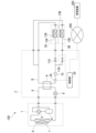
- FIG. 1 is a diagram showing a system configuration of a refrigeration cycle system according to an embodiment of the present disclosure.
- 2 is a schematic block diagram showing the functional configuration of a management device 300 in the embodiment.
- FIG. 13 is a table showing an example of water quality information stored in a storage unit 305 in the embodiment.
- 4 is a table showing an example of driving information stored in a storage unit 305 in the embodiment.
- 10 is a flowchart illustrating the operation of a management device 300 in the embodiment.
- 4 is a flowchart illustrating the operation of a control unit 30 in the embodiment.
- FIG. 2 is an explanatory diagram illustrating a hardware configuration of a management device 300 according to the embodiment.
- an air conditioner will be described as an example of a refrigeration cycle device.
- the refrigeration cycle device has a refrigerant circuit and a load circuit and uses a water refrigerant as a heat medium circulating through the load circuit, it is not limited to an air conditioner, and may be other devices such as a circulating water heater.
- the refrigeration cycle system of the present disclosure includes a refrigeration cycle device, a sensor that detects the water quality of the water refrigerant of the refrigeration cycle device, and a management device that collects water quality information indicating the water quality of the water refrigerant detected by the sensor and determines whether the water quality information satisfies a predetermined condition, and the refrigeration cycle device limits the flow rate of the water refrigerant when the management device determines that the water quality information satisfies the predetermined condition. This makes it possible to suppress the progression of corrosion of the piping that occurs when operation is continued under conditions where the water refrigerant has a problem with its water quality more than before.
- FIG. 1 is a diagram showing the system configuration of a refrigeration cycle system in one embodiment of the present disclosure.
- the refrigeration cycle system in this embodiment includes an air conditioning device 100 and a management device 300 communicatively connected to the air conditioning device 100 via a network 200.
- the refrigeration cycle system may include multiple air conditioning devices 100, and the management device 300 may be communicatively connected to the multiple air conditioning devices 100 via the network 200.
- the air conditioning device 100 has a refrigerant circuit A and a load circuit B, and uses water refrigerant as the heat medium circulating through the load circuit B.
- Refrigerant circuit A is configured to circulate heat source side refrigerant by sequentially connecting compressor 4, four-way valve 5, outdoor heat exchanger 6, throttling device 8, and load side heat exchanger 9 with piping.
- Load circuit B is configured to circulate load side refrigerant by sequentially connecting pump 10 as a medium transport device, load side heat exchanger 9, indoor heat exchangers 12A and 12B (hereinafter collectively referred to simply as "indoor heat exchanger 12"), and one flow control valve 11A and 11B (hereinafter collectively referred to simply as "flow control valve 11") with piping.
- the load side refrigerant transported by the pump 10 is circulated through the load side heat exchanger 9, then branched into multiple paths, and each of the branched load side refrigerant flows through each indoor heat exchanger 12 and each flow control valve 11 before merging and returning to the pump 10.
- the air conditioning device 100 heats or cools the load side refrigerant of the load circuit B by exchanging heat between the heat source side refrigerant of the refrigerant circuit A and the load side refrigerant of the load circuit B in the load side heat exchanger 9, and supplies the load side refrigerant of the load circuit B to the indoor heat exchanger 12, where it exchanges heat with the indoor air, thereby heating or cooling the room.
- a natural refrigerant such as freon or CO2 circulates in the refrigerant circuit A as the heat source side refrigerant
- a water refrigerant circulates in the load circuit B as the load side refrigerant (heat medium).
- a compressor 4, a four-way valve 5, an outdoor heat exchanger 6, and an outdoor unit blower 7 that blows outdoor air to the outdoor heat exchanger 6 are disposed in the outdoor unit 1.
- a throttling device 8, a load side heat exchanger 9, a pump 10, a flow control valve 11, a sensor 26, and a control unit 30 are disposed in the repeater 2.
- Indoor heat exchangers 12A, 12B and indoor unit blowers 13A, 13B (hereinafter collectively referred to simply as "indoor unit blower 13") that blow indoor air to the indoor heat exchangers 12A, 12B are disposed in the indoor units 3A, 3B (hereinafter collectively referred to simply as "indoor unit 3").
- the repeater 2 has a branch path corresponding to each indoor unit 3 on the inlet side where the water refrigerant flows in from each indoor unit 3, and a flow control valve 11 is provided on each branch path.
- the repeater 2 also has a branch path corresponding to each indoor unit 3 on the outlet side where water flows out to each indoor unit 3, and the water refrigerant flowing out from each branch path on the outlet side passes through the corresponding indoor unit 3, flows into each branch path on the inlet side, passes through the corresponding flow control valve 11, and is merged and sucked into the pump 10.
- the branch paths on the inlet side and the branch paths on the outlet side are connected by a main path having the pump 10 and the load side heat exchanger 9.
- a sensor 26 is provided on the main path from the pump 10 to the load side heat exchanger 9 to detect the water quality of the water refrigerant flowing through the main path.
- the water quality detected by the sensor 26 is, for example, hydrogen ion concentration (pH), electrical conductivity (S/m), and chloride ion concentration (mg/L).
- the sensor 26 may also detect the temperature of the water refrigerant.
- the control unit 30 obtains water quality information indicating the quality of the water refrigerant as a measurement result by the sensor 26, and transmits this information to the management device 300 via the network 200.
- the control unit 30 also receives an upper limit for the flow rate of the water refrigerant from the management device 300 via the network 200.
- the upper limit for the flow rate may be set for each indoor unit 3A, 3B, or may be the combined value for the indoor units 3A, 3B. When the upper limit is set, the control unit 30 follows the set upper limit when controlling the opening degree of the flow rate adjustment valve 11.
- the control unit 30 may divide the set upper limit equally to set the upper limit value of the flow rate in each flow control valve 11, or may limit the flow rate of the flow control valve 11 with the highest flow rate so that the total value of the flow rates in each flow control valve 11 does not exceed the set upper limit value.
- the control unit 30 may obtain the pressure on the inlet and outlet sides of each flow control valve 11 and calculate the flow rate from the difference, or may calculate it from the rotation speed of the pump 10.
- the control unit 30 transmits the temperature of the water refrigerant detected by the sensor 26 and operation information indicating the flow rate of the water refrigerant to the management device 300 via the network 200.
- the pressure difference between the inlet and outlet sides of the flow control valve 11, the opening degree of the flow control valve 11, or the rotation speed of the pump 10 may be used instead of the flow rate.
- the network 200 is a network such as a mobile communication network or the Internet.
- the management device 300 collects water quality information indicating the water quality detected by the sensor 26, and limits the flow rate of the water refrigerant of the air conditioning device 100 when the water quality information satisfies a predetermined condition.
- the management device 300 further collects abnormality information indicating an abnormality that has occurred in the air conditioning device 100, detects a correlation between the water quality information and the abnormality information, and determines the predetermined condition.
- the management device 300 may collect operation information of the air conditioning device 100 and abnormality information indicating an abnormality that has occurred in the air conditioning device 100, detect a correlation between the water quality information and the operation information, and the abnormality information, and determine the predetermined condition.
- the management device 300 may generate a trained model that represents any of these correlations by machine learning.
- the management device 300 may be realized by one or more computers reading and executing a program, or may be located on a so-called cloud.
- FIG. 2 is a schematic block diagram showing the functional configuration of the management device 300 in this embodiment.
- the management device 300 includes an information receiving unit 301, a water quality abnormality determination unit 302, a flow rate restriction determination unit 303, a flow rate restriction notification unit 304, a memory unit 305, a condition determination unit 306, an administrator notification unit 307, and an apparatus abnormality acquisition unit 308.
- the information receiving unit 301 receives water quality information from the control unit 30 and stores it in the memory unit 305. Furthermore, the information receiving unit 301 may receive operation information from the control unit 30 and store it in the memory unit 305.
- the water quality abnormality determination unit 302 uses the trained model generated by the condition determination unit 306 to determine whether the water quality information received by the information receiving unit 301 satisfies a predetermined condition. For example, the water quality abnormality determination unit 302 inputs the water quality information received by the information receiving unit 301 into the trained model generated by the condition determination unit 306, calculates the probability that an abnormality will occur in the air conditioning device 100 by a predetermined time after a predetermined period of time has passed, and determines that the predetermined condition is satisfied if the probability is equal to or greater than a threshold. The water quality abnormality determination unit 302 may further input the total operating time of the air conditioning device 100 or may input operating information into the trained model.
- the total operating time is the accumulated value of the time the air conditioning device 100 has been operated since its installation or the elapsed time since its installation, and may be received by the information receiving unit 301 from the control unit 30 or may be calculated by the water quality abnormality determination unit 302.
- the water quality abnormality determination unit 302 may also read out the water quality information and operating information for the period required for input to the trained model from the storage unit 305.
- the flow rate limit determination unit 303 determines the upper limit of the water refrigerant flow rate in the air conditioning device 100.
- the upper limit may be determined based on the device configuration of the air conditioning device 100, such as the number of indoor units 3, the model of the indoor units 3, and the model of the repeater 2, or may be determined based on the likelihood of an abnormality occurring calculated by the water quality abnormality determination unit 302, or may be determined based on a combination of these.
- the flow rate limit notification unit 304 notifies the control unit 30 of the upper limit value determined by the flow rate limit determination unit 303 via the network 200.
- the storage unit 305 stores the water quality information received by the information receiving unit 301 and the abnormality information acquired by the device abnormality acquisition unit 308. Furthermore, the storage unit 305 may store the operation information received by the information receiving unit 301.
- the condition determination unit 306 uses the water quality information and anomaly information stored in the memory unit 305 to detect correlations between the water quality information and the anomaly information through machine learning, and generates a trained model that calculates the likelihood that an anomaly will occur in the air conditioning device 100 by a specified time after a specified period of time has passed.
- the condition determination unit 306 may use the water quality information, operation information, and anomaly information stored in the memory unit 305 to detect correlations between the water quality information and operation information, and the anomaly information through machine learning, and generate a trained model that calculates the likelihood that an anomaly will occur in the air conditioning device 100 by a specified time after a specified period of time has passed.
- These models generated by machine learning may be any of neural networks such as a transformer, a convolutional neural network (CNN) or a recurrent neural network (RNN), a support vector machine (SVM), etc.
- the administrator notification unit 307 notifies the administrator of the air conditioning device 100 of the water quality abnormality.
- This notification may be made, for example, by sending an email to the email address associated with the administrator, or by sending an SMS (Short Message Service) or voice message to the telephone number associated with the administrator.
- the administrator may be the owner, maintenance person, or user of the air conditioning device 100. This notification may also be to encourage the replacement of the water refrigerant in the air conditioning device 100.
- the timing at which the administrator notification unit 307 notifies the administrator and the timing at which the flow rate limit determination unit 303 determines the upper limit of the flow rate may be different. For example, if the number of times or the period during which the water quality abnormality determination unit 302 has consecutively determined that the water quality information satisfies a predetermined condition is equal to or greater than a first threshold, the administrator notification unit 307 may notify the administrator, and if the number of times or the period is equal to a second threshold, the flow rate limit determination unit 303 may determine the upper limit of the flow rate.
- the first threshold may be one time.
- the second threshold is a value equal to or greater than the first threshold. This makes it possible to limit the flow rate of the water refrigerant only when the water refrigerant is not replaced even if the administrator is notified and a state with a high probability of an abnormality occurring continues.
- the device abnormality acquisition unit 308 collects abnormality information indicating an abnormality that has occurred in the air conditioning device 100.
- the abnormality information indicates, for example, the occurrence and timing of an abnormality, such as corrosion of the piping of the load circuit B. This collection may be performed, for example, by the operator of the management device 300 inputting the information using a keyboard, mouse, etc.
- Figure 3 is a table showing an example of water quality information stored by the memory unit 305 in this embodiment.
- the memory unit 305 stores time, pH (hydrogen ion concentration), electrical conductivity, and chloride ion concentration as water quality information in association with each other.
- the memory unit 305 stores the time "202306221022” indicating 10:22 on June 22, 2023 in association with the pH "7.31", the electrical conductivity "18.8", and the chloride ion concentration "120.3".
- the memory unit 305 stores the time "202306231022”, the pH “7.32”, the electrical conductivity "18.6”, and the chloride ion concentration "121.2” in association with each other, and stores the time "202306241022", the pH “7.29”, the electrical conductivity "18.7”, and the chloride ion concentration "120.8” in association with each other.
- FIG. 4 is a table showing an example of operating information stored by the storage unit 305 in this embodiment.
- the storage unit 305 stores, as operating information, a time, a flow rate of the water refrigerant, and a temperature of the water refrigerant in association with each other.
- the storage unit 305 stores the time "202306221011” indicating 10:11 on June 22, 2023 in association with a flow rate of "3.5" and a temperature of "15.3".
- the storage unit 305 stores the time "202306221021” in association with a flow rate of "7.2” and a temperature of "16.5", and stores the time “202306221031” in association with a flow rate of "2.6” and a temperature of "15.2".
- FIG. 5 is a schematic diagram showing an example of the trained model M1 in this embodiment.
- the trained model M1 in FIG. 5 is a trained model generated by the condition determination unit 306 and used by the water quality abnormality determination unit 302.
- the trained model M1 calculates an abnormality occurrence probability R, which is the probability that an abnormality will occur at a predetermined time, such as one year later.
- the water quality information Qt and operation information Jt may each be information for a time interval of a predetermined length.
- the condition determination unit 306 may generate the trained model M1 by machine learning using teacher data based on the water quality information, operation information, and abnormality information stored in the storage unit 305.
- the teacher data has inputs of water quality information, operation information, and part or all of the total operation time, and outputs the presence or absence of an abnormality.
- FIG. 6 is a flowchart explaining the operation of the management device 300 in this embodiment.
- the flowchart in FIG. 6 is a flowchart for the case where a trained model has already been generated by the condition determination unit 306.
- the information receiving unit 301 performs a process for receiving information from the control unit 30 (step Sa1).
- the information receiving unit 301 determines whether or not water quality information has been received in step Sa1 (step Sa2).
- step Sa2-No the information receiving unit 301 determines whether or not operation information has been received in step Sa1 (step Sa10). If it is determined that operation information has been received (step Sa10-Yes), the information receiving unit 301 stores the received operation information in the storage unit 305 (step Sa11), and the process returns to step Sa1. If it is determined that operation information has not been received (step Sa10-No), the process returns to step Sa1.
- step Sa2 If it is determined in step Sa2 that water quality information has been received (step Sa2-Yes), the information receiving unit 301 stores the received water quality information in the memory unit 305 (step Sa3).
- the water quality abnormality determination unit 302 inputs the water quality information, operation information, and total operation time into the learned model to calculate the probability of an abnormality occurring.
- the water quality abnormality determination unit 302 determines a water quality abnormality based on whether the calculated probability of an abnormality occurring exceeds a threshold value (step Sa4). If it is determined that the probability of an abnormality occurring does not exceed the threshold value and there is no water quality abnormality (step Sa5-No), the process returns to step Sa1.
- step Sa5-Yes if the probability of an abnormality exceeds the threshold and it is determined that there is a water quality abnormality (step Sa5-Yes), the administrator notification unit 307 notifies the administrator of the water quality abnormality (step Sa6).
- the flow rate restriction determination unit 303 determines whether the number of times that it has been determined that there is a water quality abnormality is equal to or greater than the threshold ⁇ (step Sa7). If it is determined that the number of times that it has been determined that there is a water quality abnormality is not equal to or greater than the threshold ⁇ (step Sa7-No), the process returns to step Sa1.
- step Sa7-Yes if it is determined that the number of times the water quality has been determined to be abnormal is equal to or greater than the threshold value ⁇ (step Sa7-Yes), the flow rate limit determination unit 303 determines the upper limit of the water refrigerant flow rate (step Sa8). Next, the flow rate limit notification unit 304 notifies the control unit 30 of the upper limit determined in step Sa8 (step Sa9), and the process returns to step Sa1.
- the flowchart in FIG. 6 is an example in which the first threshold is 1 time and the second threshold is ⁇ times.
- FIG. 7 is a flowchart explaining the operation of the control unit 30 in this embodiment.
- the control unit 30 acquires operating information and transmits it to the management device 300 (step Sb1).
- the control unit 30 may acquire the pressures on the inlet and outlet sides of the flow control valve 11 and calculate the flow rate of the water refrigerant from the difference between them, or may use the opening degree of the flow control valve 11 in place of the flow rate.
- the control unit 30 uses the temperature of the water refrigerant detected by the sensor 26.
- the control unit 30 determines whether or not to transmit water quality information (step Sb2). This determination is made based on whether or not it is the time to transmit water quality information. If it is not the time to transmit water quality information and it is determined that the water quality information should not be transmitted (step Sb2-No), the process returns to step Sb1. If it is the time to transmit water quality information and it is determined that the water quality information should be transmitted (step Sb2-Yes), the control unit 30 measures the water quality of the water refrigerant using the sensor 26 (step Sb3). Next, the control unit 30 transmits the measurement result of step Sb3 to the management device 300 as water quality information (step Sb4).
- step Sb5 the control unit 30 performs a reception process. If a flow rate limit is received from the management device 300 through this reception process (step Sb5-Yes), the flow rate limit (upper limit value) of the water refrigerant is set (step Sb7) and the process returns to step Sb1. If a flow rate limit is not received in step Sb5 (step Sb5-No), the process returns to step Sb1.
- whether or not to limit the flow rate of the water refrigerant is determined using a trained model, but the flow rate may also be limited if the water quality information exceeds a predetermined range.
- FIG. 8 is an explanatory diagram illustrating the hardware configuration of the management device 300 according to this embodiment.
- the management device 300 is configured to include an input/output module I, a storage module M, and a control module P.
- the input/output module I is realized by including a part or all of a communication module H11, a connection module H12, a pointing device H21, a keyboard H22, a display H23, a button H3, a microphone H41, a speaker H42, a camera H51, or a sensor H52.
- the storage module M is realized by including a drive H7.
- the storage module M may further be configured to include a part or all of a memory H8.
- the control module P is realized by including a memory H8 and a processor H9. These hardware components are connected to each other so as to be able to communicate with each other via a bus, and are supplied with power from a power source H6.
- the connection module H12 is a digital input/output port such as a USB (Universal Serial Bus).
- the pointing device H21, the keyboard H22, and the display H23 are touch panels.
- the sensor H52 is an acceleration sensor, a gyro sensor, a GPS receiving module, a proximity sensor, etc.
- the power source H6 is a power supply unit that supplies the electricity required to operate each device. In the case of a portable device, the power source H6 is a battery.
- the drive H7 is an auxiliary storage medium such as a hard disk drive or a solid state drive.
- the drive H7 may be a non-volatile memory such as an EEPROM or a flash memory, or a magneto-optical disk drive or a flexible disk drive.
- the drive H7 is not limited to a drive built into each device, but may be an external storage device connected to the connector of the connection module H12.
- the memory H8 is a main storage medium such as a random access memory.
- the memory H8 may be a cache memory.
- the memory H8 stores instructions when the instructions are executed by one or more processors H9.
- the processor H9 is a CPU (Central Processing Unit).
- the processor H9 may be an MPU (Microprocessing Unit) or a GPU (Graphics Processing Unit).
- the processor H9 reads programs and various data from the drive H7 via the memory H8 and performs calculations to execute the instructions stored in the one or more memories H8.
- management device 300 may be replaced with the term “control module P.”
- One embodiment of the present disclosure is a refrigeration cycle apparatus having a refrigerant circuit and a load circuit, and using a water refrigerant as a heat medium circulating through the load circuit, a sensor for detecting a water quality of the water refrigerant, and a management device for collecting water quality information indicating the water quality detected by the sensor and determining whether the water quality information satisfies predetermined conditions, wherein the refrigeration cycle apparatus is a refrigeration cycle system that limits the flow rate of the water refrigerant when the management device determines that the water quality information satisfies the predetermined conditions.
- the refrigeration cycle system can more effectively prevent the progression of corrosion in the pipes that occurs when the system continues to operate under conditions where there is a problem with the water refrigerant quality.
- Another embodiment of the present disclosure is the refrigeration cycle system described in (1), in which the management device collects abnormality information indicating an abnormality that has occurred in the refrigeration cycle device, detects a correlation between the water quality information and the abnormality information, and determines the predetermined conditions.
- Another embodiment of the present disclosure is a refrigeration cycle system as described in any one of (1) to (3), in which the management device notifies the refrigeration cycle device of an upper limit value of the flow rate of the water refrigerant when the management device determines that the water quality information satisfies a predetermined condition.
- Another embodiment of the present disclosure is a refrigeration cycle system as described in (2) or (3), in which the management device generates a trained model representing the correlation by machine learning.
- Another embodiment of the present disclosure is a management device in a refrigeration cycle system that includes a refrigeration cycle device having a refrigerant circuit and a load circuit and using a water refrigerant as a heat medium circulating through the load circuit, and a management device, the management device collecting water quality information indicating the water quality of the water refrigerant, and when it is determined that the water quality information satisfies a predetermined condition, causing the refrigeration cycle device to limit the flow rate of the water refrigerant.
- a program for implementing the functions of management device 300 in FIG. 1 may be recorded on a computer-readable recording medium, and the program recorded on the recording medium may be read into a computer system and executed to implement management device 300.
- the term "computer system” here includes hardware such as the OS and peripheral devices.
- Computer-readable recording media refers to portable media such as flexible disks, optical magnetic disks, ROMs, and CD-ROMs, as well as storage devices such as hard disks built into computer systems.
- “computer-readable recording media” also includes devices that dynamically store programs for a short period of time, such as communication lines when transmitting programs via networks such as the Internet or communication lines such as telephone lines, and devices that store programs for a certain period of time, such as volatile memory within computer systems that act as servers or clients in such cases.
- the above programs may be ones that realize some of the functions described above, or may be ones that can realize the functions described above in combination with programs already recorded in the computer system.
Landscapes
- Engineering & Computer Science (AREA)
- Mechanical Engineering (AREA)
- General Engineering & Computer Science (AREA)
- Physics & Mathematics (AREA)
- Thermal Sciences (AREA)
- Chemical & Material Sciences (AREA)
- Combustion & Propulsion (AREA)
- Air Conditioning Control Device (AREA)
Priority Applications (2)
| Application Number | Priority Date | Filing Date | Title |
|---|---|---|---|
| JP2024513688A JPWO2025052569A1 (https=) | 2023-09-06 | 2023-09-06 | |
| PCT/JP2023/032491 WO2025052569A1 (ja) | 2023-09-06 | 2023-09-06 | 冷凍サイクルシステム、冷凍サイクル装置、管理装置、管理方法、およびプログラム |
Applications Claiming Priority (1)
| Application Number | Priority Date | Filing Date | Title |
|---|---|---|---|
| PCT/JP2023/032491 WO2025052569A1 (ja) | 2023-09-06 | 2023-09-06 | 冷凍サイクルシステム、冷凍サイクル装置、管理装置、管理方法、およびプログラム |
Publications (1)
| Publication Number | Publication Date |
|---|---|
| WO2025052569A1 true WO2025052569A1 (ja) | 2025-03-13 |
Family
ID=94923299
Family Applications (1)
| Application Number | Title | Priority Date | Filing Date |
|---|---|---|---|
| PCT/JP2023/032491 Pending WO2025052569A1 (ja) | 2023-09-06 | 2023-09-06 | 冷凍サイクルシステム、冷凍サイクル装置、管理装置、管理方法、およびプログラム |
Country Status (2)
| Country | Link |
|---|---|
| JP (1) | JPWO2025052569A1 (https=) |
| WO (1) | WO2025052569A1 (https=) |
Citations (4)
| Publication number | Priority date | Publication date | Assignee | Title |
|---|---|---|---|---|
| JPS52147956U (https=) * | 1976-05-06 | 1977-11-09 | ||
| JP2012220288A (ja) * | 2011-04-06 | 2012-11-12 | Mitsubishi Electric Corp | 防食性能劣化検知センサー並びにそれを備えた給湯暖房システム及び設備機器 |
| WO2022049763A1 (ja) * | 2020-09-07 | 2022-03-10 | 三菱電機株式会社 | 空気調和装置 |
| WO2022172452A1 (ja) * | 2021-02-15 | 2022-08-18 | 三菱電機株式会社 | データ処理装置及びデータ処理方法 |
Family Cites Families (9)
| Publication number | Priority date | Publication date | Assignee | Title |
|---|---|---|---|---|
| JPH0313040U (https=) * | 1989-06-19 | 1991-02-08 | ||
| JP3490691B2 (ja) * | 2000-06-05 | 2004-01-26 | 三建設備工業株式会社 | 水蒸気圧縮冷凍機および蓄熱槽の組合せにおける水質管理システム |
| JP2006266609A (ja) * | 2005-03-24 | 2006-10-05 | Denki Bldg Co Ltd | 空調機の異常診断システム |
| JP4205113B2 (ja) * | 2005-03-31 | 2009-01-07 | 株式会社西原衛生工業所 | 循環式給湯システム |
| JP2010139161A (ja) * | 2008-12-11 | 2010-06-24 | Mitsubishi Heavy Ind Ltd | 空気調和機および家電製品 |
| JP2012242034A (ja) * | 2011-05-23 | 2012-12-10 | Panasonic Corp | 空気調和機 |
| JP6164400B2 (ja) * | 2013-02-28 | 2017-07-19 | アイシン精機株式会社 | エンジン駆動式空調装置 |
| CN214683303U (zh) * | 2021-02-03 | 2021-11-12 | 长春市鲲鹏机电工程设备有限公司 | 一种空调管道清洗机 |
| CN115220502A (zh) * | 2022-07-13 | 2022-10-21 | 朗森特环境科技(山东)有限公司 | 一种空调循环水水质控制系统 |
-
2023
- 2023-09-06 WO PCT/JP2023/032491 patent/WO2025052569A1/ja active Pending
- 2023-09-06 JP JP2024513688A patent/JPWO2025052569A1/ja active Pending
Patent Citations (4)
| Publication number | Priority date | Publication date | Assignee | Title |
|---|---|---|---|---|
| JPS52147956U (https=) * | 1976-05-06 | 1977-11-09 | ||
| JP2012220288A (ja) * | 2011-04-06 | 2012-11-12 | Mitsubishi Electric Corp | 防食性能劣化検知センサー並びにそれを備えた給湯暖房システム及び設備機器 |
| WO2022049763A1 (ja) * | 2020-09-07 | 2022-03-10 | 三菱電機株式会社 | 空気調和装置 |
| WO2022172452A1 (ja) * | 2021-02-15 | 2022-08-18 | 三菱電機株式会社 | データ処理装置及びデータ処理方法 |
Non-Patent Citations (1)
| Title |
|---|
| "Advanced Level Standard Textbook for Refrigeration and Air Conditioning (Refrigeration Version)", 31 July 2000, JAPAN SOCIETY OF REFRIGERATING AND AIR CONDITIONING ENGINEERS, JP, ISBN: 4-88967-069-6, article JAPAN SOCIETY OF REFRIGERATING AND AIR CONDITIONING ENGINEERS: "6.1.7 Condensing pressure control", pages: 120 - 121, XP009562303 * |
Also Published As
| Publication number | Publication date |
|---|---|
| JPWO2025052569A1 (https=) | 2025-03-13 |
Similar Documents
| Publication | Publication Date | Title |
|---|---|---|
| JP5178841B2 (ja) | 空気調和装置 | |
| JP6415720B2 (ja) | 空調システム制御装置及び空調システム | |
| CN109937331B (zh) | 空调机以及空调系统 | |
| JP5247812B2 (ja) | 空気調和装置 | |
| TWI407060B (zh) | 空調控制裝置以及空調控制方法 | |
| Du et al. | Detection and diagnosis for sensor fault in HVAC systems | |
| CN104160217B (zh) | 空调控制装置以及存储介质 | |
| CN104641188B (zh) | 组合式热电热泵 | |
| CN113692516B (zh) | 供气系统 | |
| JP5030640B2 (ja) | 空気調和システム | |
| JP6685418B2 (ja) | 空調システム、空調制御装置、空調方法及びプログラム | |
| WO2013140670A1 (ja) | 熱回収プラントシステム、熱回収プラント制御装置および熱回収プラント制御方法 | |
| JP2016008788A (ja) | 空気調和システム | |
| JP2010216765A (ja) | 局所冷却システム | |
| WO2025052569A1 (ja) | 冷凍サイクルシステム、冷凍サイクル装置、管理装置、管理方法、およびプログラム | |
| US20130126625A1 (en) | Fuel Cell Heat Pump | |
| JP5044251B2 (ja) | ビル空調最適制御システム及びビル空調最適制御装置 | |
| CN105987486A (zh) | 热需要推定装置及方法、设备控制装置、方法及系统 | |
| CN115358352B (zh) | 用于定位异常传感器的方法、设备和介质 | |
| JP2009138997A (ja) | 外気冷熱回収制御システムおよび外気冷熱回収制御方法 | |
| JP6847198B2 (ja) | 熱源水制御方法及び熱源水制御装置 | |
| JP2011149615A (ja) | 空気調和システム | |
| JP7386637B2 (ja) | データ処理装置、データ処理プログラム及びデータ処理方法 | |
| JP6126020B2 (ja) | 推定値導出方法、推定値導出装置、および、プログラム | |
| CN114110916B (zh) | 空调水阀运行状态的检测方法、装置、存储介质及空调 |
Legal Events
| Date | Code | Title | Description |
|---|---|---|---|
| ENP | Entry into the national phase |
Ref document number: 2024513688 Country of ref document: JP Kind code of ref document: A |
|
| WWE | Wipo information: entry into national phase |
Ref document number: 2024513688 Country of ref document: JP |
|
| 121 | Ep: the epo has been informed by wipo that ep was designated in this application |
Ref document number: 23951470 Country of ref document: EP Kind code of ref document: A1 |