WO2025052532A1 - 電子機器 - Google Patents
電子機器 Download PDFInfo
- Publication number
- WO2025052532A1 WO2025052532A1 PCT/JP2023/032310 JP2023032310W WO2025052532A1 WO 2025052532 A1 WO2025052532 A1 WO 2025052532A1 JP 2023032310 W JP2023032310 W JP 2023032310W WO 2025052532 A1 WO2025052532 A1 WO 2025052532A1
- Authority
- WO
- WIPO (PCT)
- Prior art keywords
- housing
- cover
- conductor
- electronic device
- attached
- Prior art date
- Legal status (The legal status is an assumption and is not a legal conclusion. Google has not performed a legal analysis and makes no representation as to the accuracy of the status listed.)
- Pending
Links
Images








Classifications
-
- G—PHYSICS
- G06—COMPUTING OR CALCULATING; COUNTING
- G06F—ELECTRIC DIGITAL DATA PROCESSING
- G06F1/00—Details not covered by groups G06F3/00 - G06F13/00 and G06F21/00
- G06F1/16—Constructional details or arrangements
-
- G—PHYSICS
- G06—COMPUTING OR CALCULATING; COUNTING
- G06F—ELECTRIC DIGITAL DATA PROCESSING
- G06F1/00—Details not covered by groups G06F3/00 - G06F13/00 and G06F21/00
- G06F1/16—Constructional details or arrangements
- G06F1/18—Packaging or power distribution
-
- H—ELECTRICITY
- H05—ELECTRIC TECHNIQUES NOT OTHERWISE PROVIDED FOR
- H05K—PRINTED CIRCUITS; CASINGS OR CONSTRUCTIONAL DETAILS OF ELECTRIC APPARATUS; MANUFACTURE OF ASSEMBLAGES OF ELECTRICAL COMPONENTS
- H05K5/00—Casings, cabinets or drawers for electric apparatus
- H05K5/02—Details
-
- H—ELECTRICITY
- H05—ELECTRIC TECHNIQUES NOT OTHERWISE PROVIDED FOR
- H05K—PRINTED CIRCUITS; CASINGS OR CONSTRUCTIONAL DETAILS OF ELECTRIC APPARATUS; MANUFACTURE OF ASSEMBLAGES OF ELECTRICAL COMPONENTS
- H05K5/00—Casings, cabinets or drawers for electric apparatus
- H05K5/02—Details
- H05K5/03—Covers
Definitions
- This disclosure relates to electronic devices.
- an opening is formed in the housing to allow inspection and maintenance of the internal electronic components.
- the opening is covered with an openable cover. If the housing and cover are made of metal and a gasket is provided around the opening of the housing, the cover does not come into direct contact with the housing, so the cover may become electrostatically charged even if the housing is grounded.
- Patent Document 1 An example of this type of electronic device is disclosed in Patent Document 1.
- the electronic device disclosed in Patent Document 1 is equipped with an earth cord for bringing the door to the same potential as the housing. One end of the earth cord is fixed to the housing, and the other end is attached to a pivot shaft that supports the door so that it can be opened and closed.
- This disclosure has been made in consideration of the above circumstances, and aims to provide an electronic device that can prevent damage to the conductor that connects the cover to the same potential as the housing.
- the electronic device of the present disclosure comprises a conductive housing, a conductive cover, a conductor, and a restricting member.
- An opening is formed in the housing and is set to a reference potential.
- the cover is removably attached to the housing to cover the opening and can be opened and closed.
- the conductor electrically connects the housing and the cover, thereby making the cover the same potential as the housing.
- the restricting member restricts the cover from being removed from the housing while the conductor electrically connects the housing and the cover.
- the electronic device disclosed herein includes a restricting member that restricts the cover from being removed from the housing when the conductors are electrically connected to the housing and the cover. This makes it possible to prevent damage to the conductors.
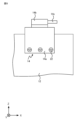
- FIG. 1 is a perspective view of an electronic device according to a first embodiment
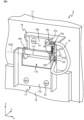
- FIG. 1 is a partial perspective view of an electronic device according to a first embodiment
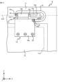
- FIG. 1 is a partial front view of an electronic device according to a first embodiment
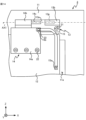
- FIG. 1 is a partial front view of a housing and a first member according to a first embodiment
- FIG. 1 is a partial front view of a cover and a second member according to the first embodiment
- FIG. 1 is a diagram showing an example of a state in which removal of a cover according to the first embodiment is restricted
- FIG. 1 is a diagram showing an example of a state in which removal of a cover according to the first embodiment is permitted
- FIG. 13 is a partial perspective view of an electronic device according to a second embodiment.
- FIG. 11 is a partial perspective view of a first member and a second member according to a second embodiment
- FIG. 13 is a diagram showing an example of a state in which removal of a cover according to a second embodiment is restricted
- FIG. 13 is a diagram showing an example of a state in which removal of a cover according to a second embodiment is permitted
- FIG. 13 is a partial front view of an electronic device according to a third embodiment
- FIG. 13 is a diagram showing an example of a state in which removal of a cover according to the third embodiment is restricted
- FIG. 13 is a diagram showing an example of a state in which removal of a cover according to a third embodiment is permitted
- FIG. 11 is a partial front view of a first modified example of the electronic device according to the embodiment
- FIG. 13 is a partial front view of a second modified example of the electronic device according to the embodiment;
- FIG. 13 is a partial perspective view of a third modified example of the electronic device according to the embodiment;
- FIG. 13 is a partial front view of a first member included in a third modified example of the electronic device according to the embodiment;
- FIG. 13 is a partial front view of the electronic device according to a fourth modified example of the embodiment;
- An example of the electronic device is a propulsion control device for a railway vehicle having a power converter, a circuit breaker, a transformer, etc. Taking a propulsion control device provided under the floor of a railway vehicle as an example, an electronic device 1 according to a first embodiment will be described.
- electronic device 1 includes conductive housing 11 set to a reference potential, conductive cover 12 removably attached to housing 11 and capable of being opened and closed to cover opening 11a of housing 11, conductor 15 electrically connecting housing 11 and cover 12 to set cover 12 to the same potential as housing 11, and restricting member 31 restricting removal of cover 12 from housing 11 while conductor 15 electrically connects housing 11 and cover 12.
- restricting member 31 prevents damage to conductor 15 caused by removal of cover 12 while conductor 15 electrically connects housing 11 and cover 12.
- the electronic device 1 includes a conductive first member 13 attached to the housing 11 and a conductive second member 14 attached to the cover 12 as a mechanism for attaching the cover 12 to the housing 11.
- the electronic device 1 includes two first members 13 and two second members 14. Each second member 14 is detachably attached to the corresponding first member 13 and is supported by the first member 13 so as to be rotatable around the rotation axis AX1.
- the conductor 15 electrically connects one of the two first members 13 to the corresponding second member 14 of the first member 13 to make them at the same potential.
- the first member 13 has the same potential as the housing 11.
- the second member 14 has the same potential as the cover 12.
- the conductor 15 makes the first member 13 and the second member 14 at the same potential, so that the housing 11 to which the first member 13 is attached and the cover 12 to which the second member 14 is attached are at the same potential.
- the Z axis indicates the vertical direction.
- the penetrating direction of the opening 11a is the Y axis direction.
- the X axis extends horizontally along the surface of the housing 11 on which the opening 11a is formed.
- the X axis, Y axis, and Z axis are mutually perpendicular. The same applies to the subsequent figures.
- the housing 11 is fixed to the underfloor of the railway vehicle via fixing members (not shown).
- the housing 11 houses a power converter, a circuit breaker, a transformer, etc.
- an opening 11a is formed in the housing 11 to allow maintenance of the electronic components housed therein.
- the housing 11 is made of a conductor and is set to a reference potential.
- the reference potential is a sufficiently low potential that allows workers to safely perform maintenance and inspection.
- the housing 11 is grounded. It is preferable that the housing 11 has a strength sufficient to prevent deformation due to vibrations caused when the railway vehicle is traveling.
- the housing 11 may be made of a metal such as aluminum, iron, or stainless steel.
- the cover 12 is removably attached to the housing 11 and covers the opening 11a and the area around the opening 11a.
- the cover 12 is attached to the housing 11 so as to be rotatable around a rotation axis AX1 indicated by a dashed line. This allows the cover 12 to be opened and closed.
- the cover 12 is made of a conductor.
- the cover 12 is made of a flat plate-shaped member made of a metal such as aluminum or stainless steel.
- the first member 13 is attached to the housing 11.
- the first member 13 is made of a conductor.
- the first member 13 is attached to the housing 11 by being fastened with a conductive fastening member 21. This makes the first member 13 have the same potential as the housing 11.
- the first member 13 and the fastening member 21 may be made of a metal such as aluminum or stainless steel.
- the first member 13 has a flat housing attachment portion 13a that is attached to the housing 11, a holding portion 13b that holds the second member 14, and a conductor attachment portion 13c to which the conductor 15 is attached.
- the housing attachment part 13a is fixed to the housing 11 by the fastening member 21 while abutting against the housing 11 with its surface.
- the housing attachment part 13a is attached to the housing 11 at a position adjacent to the opening 11a on the outer surface of the housing 11 where the opening 11a is formed.
- the holding portion 13b is continuous with the housing mounting portion 13a and has a columnar shape.
- the holding portion 13b has a cylindrical shape.
- the holding portion 13b has an insertion hole 13e into which the second member 14 is inserted.
- the second member 14 has a flat cover mounting portion 14a that is attached to the cover 12, and a shaft portion 14b whose shaft end portion 14c is inserted into an insertion hole 13e formed in the holding portion 13b of the first member 13 and rotatably supported.
- the cover mounting portion 14a is fixed to the cover 12 by the fastening member 22 with at least a portion of it abutting against the cover 12.
- the cover mounting portion 14a is attached to the cover 12 at a position that allows the shaft portion 14b to be positioned away from the cover 12, specifically, at a position adjacent to the edge of the cover 12.
- a portion of the cover mounting portion 14a abuts against the cover 12 with a surface, and another portion of the cover mounting portion 14a protrudes vertically upward from the cover 12.
- the shaft portion 14b is continuous with the cover mounting portion 14a and has a columnar shape.
- the shaft portion 14b has a cylindrical shape.
- the shaft portion 14b has a cylindrical shaft end portion 14c that extends in the direction of extension of the central axis of the cylinder.
- the shaft end portion 14c is inserted into the holding portion 13b of the first member 13. By inserting the shaft end portion 14c into the holding portion 13b, the shaft portion 14b is supported so as to be rotatable around the rotation axis AX1.
- the second member 14 is moved in the positive direction of the X-axis to insert the shaft end 14c of the shaft portion 14b of the second member 14 into the insertion hole 13e of the holding portion 13b of the first member 13, thereby removably attaching the second member 14 to the first member 13.
- This allows the cover 12 to be removably attached to the housing 11.
- the conductor 15 electrically connects the housing 11 and the cover 12. By electrically connecting the housing 11 and the cover 12, the conductor 15 makes the cover 12 have the same potential as the housing 11.
- the first end 15a of the conductor 15 is attached to the first member 13.
- the first end 15a of the conductor 15 is a crimp terminal, and is attached to the conductor attachment portion 13c of the first member 13 by the restricting member 31 while abutting the conductor attachment portion 13c of the first member 13 with a surface of the conductor 15 abutting the conductor attachment portion 13c.
- the other end of the conductor 15, the second end 15b, is attached to the second member 14.
- the second end 15b of the conductor 15 is a crimp terminal, and is attached to the cover mounting portion 14a of the second member 14 by a fastening member 33 while abutting against the cover mounting portion 14a of the second member 14 with its surface.
- the conductor 15 is formed of a conductor and an insulating member that covers the conductor with both ends of the conductor exposed.
- the conductor 15 is preferably formed of a member, such as a flexible wire, that is flexible enough to allow the cover 12 to be opened and closed while the casing 11 and the cover 12 are electrically connected. By forming the conductor 15 from a flexible wire, the conductor 15 is prevented from being damaged when the cover 12 is opened and closed.
- the state in which the conductor 15 electrically connects the casing 11 and the cover 12 refers to a state in which the first end 15a of the conductor 15 is connected to the casing 11 or the first member 13 to which the first end 15a of the conductor 15 is attached when the electronic device 1 is operating, and the second end 15b is connected to the cover 12 or the second member 14 to which the second end 15b of the conductor 15 is attached when the electronic device 1 is operating.
- the restricting member 31 is an attachment member, specifically a fastening member, that detachably attaches the conductor 15 to the first member 13.
- the restricting member 31 has a head 31a and a shaft portion 31b that extends from the head 31a and has a threaded groove formed therein.
- the diameter of the head 31a is larger than the diameter of the insertion hole 13d formed in the conductor attachment portion 13c.
- the shaft portion 31b is inserted into the insertion hole 13d formed in the conductor attachment portion 13c of the first member 13.
- the restricting member 31 is inserted into the insertion hole 13d of the conductor attachment portion 13c, and a nut 32 is provided on the opposite side of the head 31a to the conductor attachment portion 13c, thereby screwing the first end portion 15a to the conductor attachment portion 13c.
- the state in which the conductor 15 is electrically separated from at least one of the housing 11 and the cover 12 refers to at least one of the following: the first end 15a of the conductor 15 is removed from the housing 11 or the first member 13 to which the first end 15a is attached when the electronic device 1 is in operation; and the second end 15b is removed from the cover 12 or the second member 14 to which the second end 15b of the conductor 15 is attached when the electronic device 1 is in operation.
- the limiting member 31 restricts movement of the cover 12 in a direction to remove it from the housing 11 when the conductor 15 electrically connects the first member 13 and the second member 14.
- the limiting member 31 restricts movement of the second member 14 in a direction to remove it from the first member 13 when the conductor 15 is attached to the first member 13.
- the head 31a of the limiting member 31 abuts against the shaft portion 14b of the second member 14, thereby restricting movement of the second member 14 in the negative direction of the X-axis from the state shown in FIG. 6. This restricts removal of the cover 12 from the housing 11.
- the limiting member 31 when the conductor 15 is removed from the first member 13, the limiting member 31 allows the cover 12 to be moved in a direction to be removed from the housing 11.
- the first end 15a is removed from the conductor attachment portion 13c of the first member 13.
- the second member 14 is allowed to be moved in the negative direction of the X-axis. This allows the cover 12 to be removed from the housing 11.
- the cover 12 is moved in the positive direction of the X-axis, and the shaft end 14c of the shaft 14b of the second member 14 attached to the cover 12 is inserted into the holding portion 13b of the first member 13, thereby attaching the cover 12 to the housing 11.
- the conductor 15 is pulled in the direction of movement of the cover 12 when attaching the cover 12 to the housing 11, and then pulled in the opposite direction.
- the conductor 15 is pulled along the holding portion 13b of the first member 13 and the shaft 14b of the second member 14.
- the first end 15a is attached to the conductor attachment portion 13c of the first member 13, so that the cover 12 has the same potential as the housing 11.
- the restricting member 31 restricts the cover 12 from being removed from the housing 11. This prevents the conductor 15 from being damaged when the cover 12 is removed from the housing 11 with the conductor 15 attached.
- the conductor 15 is first pulled in the direction of movement of the cover 12 when the cover 12 is attached to the housing 11, and then pulled in the opposite direction, so that the cover 12 is electrically connected to the housing 11 and has the same potential, allowing the cover 12 to be opened and closed without damaging the conductor 15.
- the mechanism for attaching the cover 12 to the housing 11 is not limited to the example in the first embodiment, and may be any mechanism that allows the cover 12 to be detachably attached to the housing 11 and allows the cover 12 to be opened and closed.
- An electronic device having a mechanism different from that in the first embodiment will be described in the second embodiment, focusing on the differences from the first embodiment.
- the electronic device 2 includes a conductive first member 16 attached to the housing 11 and a conductive second member 17 attached to the cover 12.
- the second member 17 is detachably attached to the first member 16 and is supported by the first member 16 so as to be rotatable around the rotation axis AX2.
- the first member 16 and the second member 17 may be formed of a metal such as aluminum or stainless steel.
- the first member 16 has a flat housing attachment portion 16a that is attached to the housing 11, a pair of holding portions 16b that hold the second member 17, and a conductor attachment portion 16c to which the conductor 15 is attached.
- the housing attachment part 16a is fixed to the housing 11 by the fastening member 21 while abutting against the housing 11 with its surface.
- the housing attachment part 16a is attached to the housing 11 at a position adjacent to the opening 11a on the outer surface of the housing 11 where the opening 11a is formed.
- Each holding portion 16b is continuous with the housing mounting portion 16a and has a flat plate shape extending in a direction away from the housing mounting portion 16a.
- the holding portion 16b is formed of a flat plate member having a notch extending vertically from the top to the bottom and a main surface parallel to the YZ plane.
- the notch of the holding portion 16b has a shape that allows the second member 17 to be engaged.
- the conductor mounting portion 16c is continuous with the housing mounting portion 16a and has a flat plate shape extending in a direction away from the housing mounting portion 16a.
- the conductor mounting portion 16c is formed of a flat plate member having a main surface parallel to the XY plane.
- the first end portion 15a is attached to the conductor mounting portion 16c.
- an insertion hole 16d is formed in the conductor mounting portion 16c into which the restricting member 31 is inserted when attaching the conductor 15.
- the insertion hole 16d is preferably a screw hole having a screw groove formed in the wall surface.
- a through hole 17a is formed in the center of the second member 17.
- the second member 17 has a flat cover attachment portion 17b that is located vertically below the through hole 17a and is attached to the cover 12, a flat locking portion 17c that is located vertically above the through hole 17a and locks onto the first member 16, and a conductor attachment portion 17d to which the conductor 15 is attached.
- the cover mounting portion 17b is fixed to the cover 12 by the fastening member 22 with at least a portion of the cover mounting portion 17b in face contact with the cover 12.
- the cover mounting portion 17b is attached to the cover 12 at a position that prevents the through hole 17a from being blocked by the cover 12, specifically, at a position adjacent to the edge of the cover 12.
- the conductor mounting portion 17d is continuous with the cover mounting portion 17b and the locking portion 17c, and has a flat plate shape.
- the conductor mounting portion 17d is formed of a flat plate member having a main surface parallel to the YZ plane.
- the second end portion 15b is attached to the conductor mounting portion 17d.
- An insertion hole 17e is formed in the conductor mounting portion 17d, into which the fastening member 33 is inserted when attaching the conductor 15. It is preferable that the insertion hole 17e is a screw hole with a screw groove formed in the wall surface.
- the second member 17 having the above configuration is formed by bending a single metal plate in two places so that both ends face each other, and then forming a through hole in the part sandwiched between the two bent positions.
- the second member 17 is removably attached to the first member 16 by engaging the locking portion 17c of the second member 17 with the holding portion 16b of the first member 16. This allows the cover 12 to be removably attached to the housing 11.
- the conductor 15 electrically connects the housing 11 and the cover 12, thereby making the cover 12 the same potential as the housing 11.
- the first end 15a of the conductor 15 is a crimp terminal, and is attached to the conductor attachment portion 16c of the first member 16 by the restricting member 31 while being in face-to-face contact with the conductor attachment portion 16c.
- the second end 15b of the conductor 15 is a crimp terminal, and is attached to the conductor attachment portion 17d of the second member 17 by a fastening member 33 while being in face contact with the conductor attachment portion 17d.
- the fastening member 33 is preferably made of a metal such as aluminum or stainless steel.
- the limiting member 31 limits the movement of the second member 17 in the direction of removing it from the first member 16, i.e., in the negative Y-axis direction.
- the shaft portion 31b of the limiting member 31 abuts against the locking portion 17c of the second member 17, thereby limiting the movement of the second member 17 in the negative Y-axis direction from the state shown in FIG. 10. This limits the removal of the cover 12 from the housing 11.
- the first end 15a of the conductor 15 is removed from the conductor attachment portion 16c of the first member 16, and the second end 15b of the conductor 15 is removed from the conductor attachment portion 17d of the second member 17.
- the second member 17 is allowed to move in the negative direction of the Y axis. This allows the cover 12 to be removed from the housing 11.
- the cover 12 When attaching the cover 12 to the housing 11, the cover 12 is moved in the positive direction of the Y axis to the position shown in FIG. 11 with the locking portions 17c of the second member 17 facing the pair of holding portions 16b of the first member 16. From the state shown in FIG. 11, the locking portions 17c of the second member 17 are inserted into the notches of the pair of holding portions 16b of the first member 16 and rotated around the rotation axis AX2, and the position of the cover 12 becomes the position shown in FIG. 8. By connecting the conductor 15 to the first member 16 and the second member 17, the cover 12 and the housing 11 are at the same potential.
- the restricting member 31 restricts the cover 12 from being removed from the housing 11. This prevents the conductor 15 from being damaged when the cover 12 is removed from the housing 11 with the conductor 15 attached.
- connection position of the conductor 15 is not limited to the above-mentioned position, and may be any connection position as long as the cover 12 can be electrically connected to the housing 11 to have the same potential as the housing 11.
- An electronic device in which the conductor 15 is connected to a position different from that of the first embodiment will be described in the third embodiment, focusing on the differences from the first embodiment.
- First end 15a of conductor 15 provided in electronic device 3 according to embodiment 3 shown in FIG. 12 is connected to housing 11.
- First end 15a of conductor 15 is a crimp terminal, and is attached to housing 11 by fastening member 34 with the surface of conductor 15 abutting housing 11.
- Fastening member 34 may be made of a metal such as aluminum or stainless steel.
- the first end 15a of the conductor 15 serves as a restricting member.
- the first end 15a restricts the movement of the second member 14 in the direction of removing it from the first member 13 when the first end 15a is attached to the housing 11.
- the first end 15a which is a crimp terminal, abuts against the shaft portion 14b of the second member 14, restricting the movement of the second member 14 in the negative direction of the X-axis from the state shown in FIG. 12. This restricts the removal of the cover 12 from the housing 11.
- the cover 12 when the conducting wire 15 is removed from the housing 11, the cover 12 is permitted to be moved in a direction to be removed from the housing 11.
- the fastening member 34 when the fastening member 34 is removed, the first end 15a of the conducting wire 15 is removed from the housing 11.
- the second member 14 is permitted to be moved in the negative direction of the X-axis. This allows the cover 12 to be removed from the housing 11.
- the method of attaching the cover 12 to the housing 11 is the same as in embodiment 1. As in embodiment 1, the conductor 15 is pulled through, and then the first end 15a of the conductor 15 is attached to the housing 11 by the fastening member 34.
- the conductor 15 electrically connects the housing 11 and the cover 12
- the first end 15a of the conductor 15 abuts against the shaft portion 14b of the second member 14, restricting the removal of the cover 12 to which the second member 14 is attached from the housing 11. This prevents the conductor 15 from being damaged when the cover 12 is removed from the housing 11 with the conductor 15 attached.
- connection position of the conductor 15 may be any connection position that can electrically connect the housing 11 and the cover 12 to make the cover 12 have the same potential as the housing 11.
- the first end 15a of the conductor 15 may be attached to the housing attachment portion 13a of the first member 13.
- the first end 15a when the first end 15a is attached to the first member 13, the first end 15a abuts against the second member 14, thereby restricting movement of the second member 14 in the direction of removing it from the first member 13.
- the second end 15b may be directly attached to the cover 12.
- the second end 15b of the electronic device 1 may be directly attached to the cover 12 by a fastening member 33. The same applies to the electronic devices 2 and 3.
- the structure of the first members 13 and 16 may be any structure that is attached to the housing 11 and can rotatably support the second members 14 and 17 attached to the cover 12.
- the first member 13 shown in FIG. 17 and FIG. 18 may have a movement limiting portion 13f that limits the movement of the cover 12 in the X-axis direction when the cover 12 is closed.
- the movement limiting portion 13f is a flat plate-like member that is continuous with the housing attachment portion 13a and extends in a direction away from the housing 11.
- the movement limiting portion 13f is formed of a flat plate-like member parallel to the YZ plane.
- the main surface of the movement limiting portion 13f faces the surface of the second member 14 attached to the cover 12 on the negative X-axis direction side.
- the method of attaching the conductor 15 is not limited to fastening.
- the method of attaching the first end 15a may be any method that can maintain the state in which the first end 15a is in surface contact with the first member 13, 16 or the housing 11.
- the method of attaching the second end 15b may be any method that can maintain the state in which the second end 15b is in surface contact with the second member 14, 17 or the cover 12.
- the first end 15a and the second end 15b may be attached by fitting, welding, clamping with a clamping member, or the like.
- the method of restricting removal of the second members 14, 17 is not limited to the above example.
- the fastening member 34 which is an attachment member that attaches the first end 15a to the housing 11, may act as a restricting member.
- the fastening member 34 comes into contact with the second member 14, thereby restricting movement of the second member 14 in the direction of removing it from the first member 13.
- the restricting member 31 is preferably made of a conductor. By making the restricting member 31 of a conductor, it is possible to electrically connect the first end 15a and the first members 13 and 16 via the restricting member 31, even if the surfaces of the first members 13 and 16 are insulated.
- the fastening member 33 is preferably made of a conductor. By making the fastening member 33 of a conductor, it becomes possible to electrically connect the second end 15b and the second members 14 and 17 via the fastening member 33 even if the surfaces of the second members 14 and 17 are insulated.
- the extension direction of the rotation axes AX1 and AX2 is not limited to the horizontal direction, but may be the vertical direction or a direction intersecting the vertical and horizontal directions.
- the attachment positions of the first members 13 and 16 are not limited to the outer surface of the housing 11, but may be the inner surface of the housing 11. In this case, the second members 14 and 17 only need to be attached to the surface of the cover 12 facing the inside of the housing 11.
- the surface on which the opening 11a is formed is not limited to the side surface of the housing 11, but may be the vertical upper surface of the housing 11 or the vertical lower surface of the housing 11.
- the number and mounting positions of the first members 13 provided in the electronic device 1 are determined arbitrarily depending on the size and weight of the cover 12.
- the electronic device 1 only needs to be provided with the same number of second members 14 as the first members 13. The same is true for the electronic devices 2 and 3.
- the mounting position of the electronic device 1-3 is not limited to under the floor, and the electronic device 1-3 can be mounted anywhere, such as on the floor or on the roof. Furthermore, the electronic device 1-3 is not limited to a railroad car, and can be mounted on a moving object such as an automobile, bus, ship, or aircraft. Furthermore, the electronic device 1-3 may be installed not on a moving object, but at any location indoors or outdoors.
Landscapes
- Engineering & Computer Science (AREA)
- Theoretical Computer Science (AREA)
- Human Computer Interaction (AREA)
- Physics & Mathematics (AREA)
- General Engineering & Computer Science (AREA)
- General Physics & Mathematics (AREA)
- Microelectronics & Electronic Packaging (AREA)
- Power Engineering (AREA)
- Casings For Electric Apparatus (AREA)
Priority Applications (2)
| Application Number | Priority Date | Filing Date | Title |
|---|---|---|---|
| JP2025543980A JP7789283B2 (ja) | 2023-09-05 | 2023-09-05 | 電子機器 |
| PCT/JP2023/032310 WO2025052532A1 (ja) | 2023-09-05 | 2023-09-05 | 電子機器 |
Applications Claiming Priority (1)
| Application Number | Priority Date | Filing Date | Title |
|---|---|---|---|
| PCT/JP2023/032310 WO2025052532A1 (ja) | 2023-09-05 | 2023-09-05 | 電子機器 |
Publications (1)
| Publication Number | Publication Date |
|---|---|
| WO2025052532A1 true WO2025052532A1 (ja) | 2025-03-13 |
Family
ID=94923006
Family Applications (1)
| Application Number | Title | Priority Date | Filing Date |
|---|---|---|---|
| PCT/JP2023/032310 Pending WO2025052532A1 (ja) | 2023-09-05 | 2023-09-05 | 電子機器 |
Country Status (2)
| Country | Link |
|---|---|
| JP (1) | JP7789283B2 (https=) |
| WO (1) | WO2025052532A1 (https=) |
Citations (3)
| Publication number | Priority date | Publication date | Assignee | Title |
|---|---|---|---|---|
| JPS61180509U (https=) * | 1985-04-30 | 1986-11-11 | ||
| JPH0479296A (ja) * | 1990-07-20 | 1992-03-12 | Sharp Corp | 二つ折り電子機器の配線カバー機構 |
| JP2013157078A (ja) * | 2011-06-27 | 2013-08-15 | Nec Infrontia Corp | 情報処理装置用制御装置 |
-
2023
- 2023-09-05 WO PCT/JP2023/032310 patent/WO2025052532A1/ja active Pending
- 2023-09-05 JP JP2025543980A patent/JP7789283B2/ja active Active
Patent Citations (3)
| Publication number | Priority date | Publication date | Assignee | Title |
|---|---|---|---|---|
| JPS61180509U (https=) * | 1985-04-30 | 1986-11-11 | ||
| JPH0479296A (ja) * | 1990-07-20 | 1992-03-12 | Sharp Corp | 二つ折り電子機器の配線カバー機構 |
| JP2013157078A (ja) * | 2011-06-27 | 2013-08-15 | Nec Infrontia Corp | 情報処理装置用制御装置 |
Also Published As
| Publication number | Publication date |
|---|---|
| JPWO2025052532A1 (https=) | 2025-03-13 |
| JP7789283B2 (ja) | 2025-12-19 |
Similar Documents
| Publication | Publication Date | Title |
|---|---|---|
| CN103688424B (zh) | 用于电缆的带屏蔽壳的连接器 | |
| US11394187B2 (en) | Electric connection box and wire harness | |
| MX2010008265A (es) | Encerramiento de componente electrico. | |
| JP2014180733A (ja) | 筐体 | |
| JP7789283B2 (ja) | 電子機器 | |
| JP2019088126A (ja) | 電気接続箱 | |
| WO2021240802A1 (ja) | 端子台 | |
| JP2008108436A (ja) | ケーブル付コネクタ | |
| JP6464137B2 (ja) | 電気接続箱 | |
| JP2019176569A (ja) | バスダクトのフィードイン接続構造 | |
| JPH1037938A (ja) | ボルト脱落防止ホルダー | |
| CN115459058A (zh) | 将轨道连接到配电盘面板安装壁的装置及包括其的配电盘 | |
| JP4933162B2 (ja) | 電気接続箱 | |
| JP2005050555A (ja) | 貫通体の固定構造 | |
| HU187218B (en) | Wire relieving device for electric apparatuses | |
| WO2025104879A1 (ja) | 配線機器および鉄道車両用制御装置 | |
| JP6984465B2 (ja) | コネクタカバー | |
| JPH10257613A (ja) | 金属閉鎖形スイッチギヤ | |
| JP7116030B2 (ja) | プロテクタ | |
| CN219998823U (zh) | 一种配电控制设备 | |
| CN206023110U (zh) | 固定装置 | |
| RU2778556C1 (ru) | Корпус проходного монтажа | |
| JP2001327036A (ja) | ケーブルの接続器具 | |
| JPS6330170Y2 (https=) | ||
| CN103219679B (zh) | 电气接线盒 |
Legal Events
| Date | Code | Title | Description |
|---|---|---|---|
| 121 | Ep: the epo has been informed by wipo that ep was designated in this application |
Ref document number: 23951436 Country of ref document: EP Kind code of ref document: A1 |
|
| ENP | Entry into the national phase |
Ref document number: 2025543980 Country of ref document: JP Kind code of ref document: A |
|
| WWE | Wipo information: entry into national phase |
Ref document number: 2025543980 Country of ref document: JP |