WO2025041223A1 - モータコア、ステータ、ティース片、ラジアルギャップモータ、モータコアの製造方法、及びステータの製造方法 - Google Patents
モータコア、ステータ、ティース片、ラジアルギャップモータ、モータコアの製造方法、及びステータの製造方法 Download PDFInfo
- Publication number
- WO2025041223A1 WO2025041223A1 PCT/JP2023/029996 JP2023029996W WO2025041223A1 WO 2025041223 A1 WO2025041223 A1 WO 2025041223A1 JP 2023029996 W JP2023029996 W JP 2023029996W WO 2025041223 A1 WO2025041223 A1 WO 2025041223A1
- Authority
- WO
- WIPO (PCT)
- Prior art keywords
- back yoke
- winding
- motor core
- winding surface
- surface portion
- Prior art date
- Legal status (The legal status is an assumption and is not a legal conclusion. Google has not performed a legal analysis and makes no representation as to the accuracy of the status listed.)
- Pending
Links
Images


Classifications
-
- H—ELECTRICITY
- H02—GENERATION; CONVERSION OR DISTRIBUTION OF ELECTRIC POWER
- H02K—DYNAMO-ELECTRIC MACHINES
- H02K1/00—Details of the magnetic circuit
- H02K1/02—Details of the magnetic circuit characterised by the magnetic material
-
- H—ELECTRICITY
- H02—GENERATION; CONVERSION OR DISTRIBUTION OF ELECTRIC POWER
- H02K—DYNAMO-ELECTRIC MACHINES
- H02K1/00—Details of the magnetic circuit
- H02K1/06—Details of the magnetic circuit characterised by the shape, form or construction
- H02K1/12—Stationary parts of the magnetic circuit
- H02K1/14—Stator cores with salient poles
Definitions
- the present invention relates to a motor core, a stator, a teeth piece, a radial gap motor, a method for manufacturing a motor core, and a method for manufacturing a stator.
- Radial gap motors use a motor core (stator core) with multiple teeth extending from a circular back yoke.
- motor core stator core
- windings are wound around each tooth to generate a magnetic field.
- the windings are wound around each tooth using a method known as nozzle winding.
- nozzle winding the windings are wound around each tooth by winding the nozzle around the teeth while the wire is unwound from the tip of the nozzle.
- this type of nozzle winding there is a limit to how high the winding density can be, making it difficult to increase the magnetic flux density.
- the split core is composed of an arc-shaped back yoke and one tooth extending from the back yoke. With a split core, there are no obstacles around the teeth, so the windings can be wound around the teeth at high density. Therefore, by winding the windings around the teeth of each split core and then joining multiple split cores, the windings are wound at high density, resulting in a high magnetic flux density.
- powder compacts are sometimes used as motor cores, but it is difficult to cut powder compacts with a high degree of precision, so if multiple split cores made of powder compacts are joined using the method described above, it is difficult to subsequently cut the inner and outer circumferential surfaces of the back yoke to improve its roundness.
- the objective of this disclosure is to provide a motor core, a stator, a teeth piece, a radial gap motor, a method for manufacturing a motor core, and a method for manufacturing a stator that can obtain a high magnetic flux density and easily improve the roundness of the back yoke.
- the motor core according to the present disclosure is a motor core for a radial gap motor, and includes an annular back yoke and a plurality of teeth pieces that are configured separately from the back yoke, and the plurality of teeth pieces are joined to the back yoke so as to extend from the back yoke radially inward of the back yoke.
- the multiple teeth pieces are constructed separately from the back yoke, so the windings can be wound around each of the multiple teeth pieces before joining the multiple teeth pieces to the back yoke. This allows the windings to be wound densely around each of the multiple teeth pieces, resulting in a high magnetic flux density. Moreover, because the back yoke is formed in a circular ring shape, there is no problem with reduced roundness that accompanies joining. This makes it easy to increase the roundness of the back yoke.
- the back yoke and the multiple teeth pieces may be powder compacts.
- the back yoke and the multiple teeth pieces are powder compacts, it is difficult to cut them with high precision.
- the back yoke is not divided, so there is no problem with reduced roundness due to joining. This makes it easy to improve the roundness of the back yoke.
- the length of the back yoke in the axial direction of the back yoke may be longer than the length of the multiple teeth pieces in the axial direction.
- the length of the back yoke in the axial direction is longer than the length of the multiple teeth pieces in the axial direction.
- the back yoke may extend further in the axial direction than the teeth on at least one side of the back yoke.
- the back yoke extends further in the axial direction than the teeth on at least one side.
- each of the multiple teeth pieces has a body portion around which the winding is wound and a flange portion located at the end of the body portion opposite the back yoke, and the length of the flange portion in the axial direction of the back yoke may be longer than the length of the body portion in the axial direction.
- the length of the flange portion in the axial direction is longer than the length of the body portion in the axial direction. Therefore, a step is formed in which the flange portion is higher than the body portion in the axial direction, and this step increases the magnetic flux, thereby obtaining a higher magnetic flux density.
- each of the multiple teeth pieces has a body portion around which the winding is wound, and a flange portion located at the end of the body portion opposite the back yoke, and the flange portion may extend further in the axial direction of the back yoke than the body portion.
- the flange portion extends further in the axial direction than the body portion at least to one side. Therefore, a step is formed in which the flange portion is higher in the axial direction than the body portion, and this step increases the magnetic flux, thereby obtaining a higher magnetic flux density.
- the back yoke may have a plurality of recesses formed on the inner peripheral surface of the back yoke, and each of the plurality of teeth pieces may be fitted into each of the plurality of recesses.
- each of the plurality of teeth pieces is fitted into each of the plurality of recesses formed on the inner peripheral surface of the back yoke, so that the bonding strength between the back yoke and the plurality of teeth pieces can be increased, and the positional accuracy of the plurality of teeth pieces relative to the back yoke can be increased.
- each of the teeth pieces may have a protrusion that fits into each of the recesses.
- the protrusions of each of the teeth pieces fit into each of the recesses formed on the inner peripheral surface of the back yoke, thereby increasing the bonding strength between the back yoke and the teeth pieces and improving the positional accuracy of the teeth pieces relative to the back yoke.
- the recessed portion may be a dovetail groove and the protruding portion may be a dovetail tenon.
- the recessed portion is a dovetail groove and the protruding portion is a dovetail tenon, which can prevent the multiple teeth pieces from coming off the back yoke and increase the bonding strength between the back yoke and the multiple teeth pieces.
- each of the multiple teeth pieces has a body portion around which the windings are wound and a base portion located on the back yoke side of the body portion and fitted into each of the multiple recesses, and the length of the base portion in the circumferential direction of the back yoke may be longer than the length of the body portion in the circumferential direction.
- the multiple teeth pieces can be stably joined to the back yoke and the multiple teeth pieces can be prevented from collapsing relative to the back yoke.
- each of the multiple teeth pieces has a body portion around which the winding is wound, and a base portion located on the back yoke side of the body portion and fitted into each of the multiple recesses, and the base portion may extend beyond the body portion to at least one side in the circumferential direction of the back yoke.
- the base portion since the base portion extends beyond the body portion to at least one side in the circumferential direction, the multiple teeth pieces can be stably joined to the back yoke and the multiple teeth pieces can be prevented from collapsing relative to the back yoke.
- each of the multiple tooth pieces has a winding surface on which a winding is wound, and the winding surface has a first winding surface portion and a second winding surface portion facing in the axial direction of the back yoke, and a third winding surface portion and a fourth winding surface portion facing in the circumferential direction of the back yoke, and at least one of the first winding surface portion and the third winding surface portion, the first winding surface portion and the fourth winding surface portion, the second winding surface portion and the third winding surface portion, and the second winding surface portion and the fourth winding surface portion may be connected in a curved shape.
- At least one of the first and third winding surface portions, the first and fourth winding surface portions, the second and third winding surface portions, and the second and fourth winding surface portions are connected in a curved shape on the winding surface of each of the multiple teeth pieces, so that when the winding is wound around each of the winding surfaces of the multiple teeth pieces, the winding can be easily aligned along the winding surface. This makes it possible to suppress the winding from floating off the winding surface, thereby increasing the magnetic flux density.
- the teeth piece according to the present disclosure is joined to an annular back yoke to form any one of the motor cores [1] to [12].
- the tooth piece according to [13] has a winding surface on which the winding is wound, the winding surface having a first winding surface portion and a second winding surface portion that face each other, and a third winding surface portion and a fourth winding surface portion that are adjacent to the first winding surface portion and the second winding surface portion, and at least one of the first winding surface portion and the third winding surface portion, the first winding surface portion and the fourth winding surface portion, the second winding surface portion and the third winding surface portion, and the second winding surface portion and the fourth winding surface portion may be connected in a curved shape.
- At least one of the first winding surface portion and the third winding surface portion, the first winding surface portion and the fourth winding surface portion, the second winding surface portion and the third winding surface portion, and the second winding surface portion and the fourth winding surface portion are connected in a curved shape on the winding surface, so that when the winding is wound around the winding surface of the tooth piece, the winding can be easily aligned along the winding surface. This makes it possible to prevent the winding from floating away from the winding surface, thereby increasing the magnetic flux density.
- the stator according to the present disclosure is a stator for a radial gap motor, and includes a motor core according to any one of [1] to [12], and a winding wound around each of the multiple teeth of the motor core. Since this stator includes the motor core described above, it is possible to obtain a high magnetic flux density and easily increase the roundness of the back yoke.
- the radial gap motor according to the present disclosure includes the stator described in [15] and a rotor arranged to be rotatable relative to the stator. Since this radial gap motor includes the stator described above, it is possible to obtain a high magnetic flux density and easily increase the roundness of the back yoke.
- the manufacturing method of the motor core according to the present disclosure is a manufacturing method of the motor core according to any one of [1] to [12], and includes a preparation process of preparing an annular back yoke and a plurality of teeth pieces configured separately from the back yoke, and a joining process of joining the plurality of teeth pieces to the back yoke so that they extend from the back yoke radially inward of the back yoke.
- the method for manufacturing a stator according to the present disclosure is a method for manufacturing a stator as described in [15], and includes a preparation process for preparing a circular back yoke and a plurality of teeth pieces configured separately from the back yoke, a winding process for winding a winding around each of the plurality of teeth pieces, and a joining process for joining the plurality of teeth pieces to the back yoke so that they extend from the back yoke radially inward of the back yoke after the winding process.
- a winding is wound around each of the multiple teeth pieces, which are constructed separately from the back yoke, before the multiple teeth pieces are joined to the back yoke.
- This allows the winding to be wound densely around each of the multiple teeth pieces, resulting in a high magnetic flux density.
- the back yoke is formed in an annular shape, there is no problem with reduced roundness that accompanies joining. This makes it easy to improve the roundness of the back yoke.
- a high magnetic flux density can be obtained and the roundness of the back yoke can be easily improved.
- FIG. 1 is a schematic cross-sectional view of a radial gap motor according to an embodiment.
- FIG. 2 is a perspective view of the motor core according to the first embodiment.
- FIG. 3 is a plan view of the motor core according to the first embodiment.
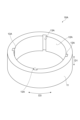
- FIG. 4 is a perspective view of the back yoke shown in FIGS. 2 and 3.
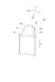
- FIG. 5 is a perspective view of the teeth piece shown in FIGS. 2 and 3.
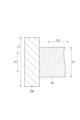
- FIG. 6 is a cross-sectional view of the teeth piece shown in FIGS. 2 and 3.
- FIG. 7 is a perspective view of a motor core according to the second embodiment.
- FIG. 8 is a plan view of a motor core according to the second embodiment.
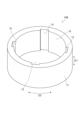
- FIG. 9 is a perspective view of the back yoke shown in FIGS.
- FIG. 10 is a perspective view of the tooth piece shown in FIGS. 6 and 7.
- FIG. FIG. 11 is a perspective view of a motor core according to the third embodiment.
- FIG. 12 is a perspective view of the back yoke shown in FIG.
- FIG. 13 is a cross-sectional view of the motor core shown in FIG.
- FIG. 14 is a perspective view of a motor core according to the fourth embodiment.
- FIG. 17 is a perspective view of a motor core according to the fifth embodiment.
- 18 is a perspective view of the tooth piece shown in FIG. 17.
- FIG. 17 is a perspective view of
- FIG. 19 is a cross-sectional view of the tooth piece shown in FIG. 17.
- FIG. 20 is a cross-sectional view of the tooth piece shown in FIG. 17.
- FIG. FIG. 21 is a perspective view of a motor core according to the sixth embodiment.
- FIG. 22 is a plan view of a motor core according to the sixth embodiment.
- FIG. 23 is a perspective view of the back yoke shown in FIGS. 21 and 22.
- FIG. FIG. 24 is a perspective view of the tooth piece shown in FIGS. 21 and 22.
- FIG. FIG. 25 is a cross-sectional view of the motor core shown in FIGS. 21 and 22.
- Fig. 1 is a schematic cross-sectional view of a radial gap motor according to an embodiment.
- a radial gap motor 1 according to this embodiment includes a stator 2, a rotor 3 arranged rotatably relative to the stator 2, and a shaft 4 fixed to the rotor 3.
- the stator 2 and the rotor 3 are arranged to be spaced apart in the radial direction of the shaft 4.
- a shaft hole 5 through which the shaft 4 is inserted is formed in the center of the rotor 3.
- the stator 2 is a stator for a radial gap motor 1.
- the stator 2 includes a motor core 6 and a winding 7 wound around the motor core 6.
- the motor core 6 is the portion of the stator 2 excluding the winding 7, and is also called a stator core.
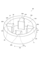
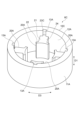
- Fig. 2 is a perspective view of the motor core according to the first embodiment.
- Fig. 3 is a plan view of the motor core according to the first embodiment.
- the motor core 6 according to this embodiment includes an annular back yoke 10 and a plurality of tooth pieces 20 that are formed separately from the back yoke 10 and joined to the back yoke 10.
- the motor core 6 is described as including four tooth pieces 20, but the number of tooth pieces 20 is not particularly limited as long as it is two or more.
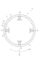
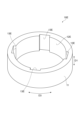
- FIG. 4 is a perspective view of the back yoke shown in FIGS. 2 and 3.
- the back yoke 10 is formed in a circular ring shape without being divided into multiple parts.
- the axial direction of the back yoke 10 is called the axial direction D1
- the radial direction of the back yoke 10 is called the radial direction D2
- the circumferential direction of the back yoke 10 is called the circumferential direction D3.
- the axial direction D1 is also the thickness direction of the back yoke 10 (the rotational axis direction of the rotor 3 in the radial gap motor 1).
- the radial direction D2 is also the radial direction of the ring formed by the back yoke 10 (the radial direction of the rotor 3 in the radial gap motor 1).
- the circumferential direction D3 is also the circumferential direction of the ring formed by the back yoke 10 (the rotational direction of the rotor 3 in the radial gap motor 1).
- the outer peripheral surface 11 of the back yoke 10 is formed in a perfect circle.
- a perfect circle includes not only a completely perfect circle shape, but also an approximately perfect circle shape that has been deformed due to manufacturing errors, etc.
- the inner peripheral surface 12 of the back yoke 10 may be formed in a perfect circle shape, or may be polygonal to make it easier to join multiple teeth pieces 20 to the back yoke 10.
- a plurality of recesses 13 are formed on the inner peripheral surface 12 of the back yoke 10.
- the recesses 13 are positioned at equal intervals in the circumferential direction D3.
- the number of recesses 13 is the same as the number of tooth pieces 20.
- Each of the recesses 13 extends from the inner peripheral surface 12 of the back yoke 10 toward the outside in the radial direction D2 and penetrates the back yoke 10 in the axial direction D1.
- the back yoke 10 is, for example, a powder compact formed by pressing soft magnetic powder coated with an insulating material.
- the powder compact back yoke 10 can be molded, for example, by a commercially available powder compacting device.
- the soft magnetic powder material is, for example, pure iron, iron silicon, or iron cobalt.
- the average particle size of the soft magnetic powder is, for example, 3 ⁇ m to 300 ⁇ m, 30 ⁇ m to 200 ⁇ m, or 50 ⁇ m to 150 ⁇ m.
- the insulating material is, for example, an insulating coating containing phosphoric acid, silicone, or the like.
- the average particle size of the soft magnetic powder is measured by a robot shifter (model number: RPS-205) manufactured by Seishin Enterprise Co., Ltd.
- the back yoke 10 may be a laminate in which multiple electromagnetic steel sheets are stacked.
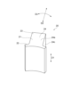
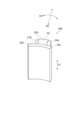
- FIG. 5 is a perspective view of the tooth piece shown in FIGS. 2 and 3.
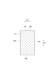
- FIG. 6 is a cross-sectional view of the tooth piece shown in FIGS. 2 and 3.
- the multiple tooth pieces 20 are joined to an annular back yoke 10 to form a motor core 6.
- Each of the multiple tooth pieces 20 is a portion around which the windings 7 are wound.
- Each of the multiple tooth pieces 20 is fitted into a respective one of multiple recesses 13 formed on the inner circumferential surface 12 of the back yoke 10.
- the multiple tooth pieces 20 are joined to the back yoke 10 so as to extend inward in the radial direction D2 from the back yoke 10.
- Each of the multiple tooth pieces 20 has a body 21 around which the winding 7 is wound, a flange 22 located at the end of the body 21 opposite the back yoke 10, and a base 23 located on the back yoke 10 side of the body 21 (opposite the flange 22).
- Each of the multiple tooth pieces 20 is joined to the back yoke 10 by fitting the base 23 into each of multiple recesses 13 formed on the inner surface 12 of the back yoke 10.
- the body 21 and base 23 extend linearly in the radial direction D2.
- the cross-sectional shape of the body 21 and base 23 in a direction perpendicular to the radial direction D2 is, for example, rectangular.
- the body 21 has a winding surface 24 around which the winding 7 is wound.
- the winding surface 24 is the surface of the body 21 around the radial direction D2, and is the surface of the body 21 that extends from the inner peripheral surface 12 of the back yoke 10 to the flange portion 22.
- the winding surface 24 has a first winding surface portion 24a and a second winding surface portion 24b that face the axial direction D1, and a third winding surface portion 24c and a fourth winding surface portion 24d that face the circumferential direction D3.
- the first winding surface portion 24a and the second winding surface portion 24b are adjacent to the third winding surface portion 24c on one side in the circumferential direction D3, and the first winding surface portion 24a and the second winding surface portion 24b are adjacent to the fourth winding surface portion 24d on the other side in the circumferential direction D3. Additionally, the third winding surface portion 24c and the fourth winding surface portion 24d are adjacent to the first winding surface portion 24a on one side in the axial direction D1, and the third winding surface portion 24c and the fourth winding surface portion 24d are adjacent to the second winding surface portion 24b on the other side in the axial direction D1.
- the flange 22 forms the inner circumferential surface of the stator 2 and the motor core 6.
- the length of the flange 22 in the circumferential direction D3 is longer than the length of the body 21 in the circumferential direction D3.
- the flange 22 extends beyond the body 21 to at least one side in the circumferential direction D3. In other words, when viewed from the radial direction D2, the flange 22 protrudes from the body 21 to at least one side in the circumferential direction D3. In this embodiment, the flange 22 extends beyond the body 21 to both sides in the circumferential direction D3. In other words, when viewed from the radial direction D2, the flange 22 protrudes from the body 21 to both sides in the circumferential direction D3.
- the multiple teeth pieces 20 are, for example, a powder compact formed by pressing soft magnetic powder coated with an insulating material.
- the multiple teeth pieces 20, which are powder compacts, can be molded, for example, by a commercially available powder compacting device.
- the soft magnetic powder material is, for example, pure iron, iron silicon, or iron cobalt.
- the average particle size of the soft magnetic powder is, for example, 3 ⁇ m to 300 ⁇ m, 30 ⁇ m to 200 ⁇ m, or 50 ⁇ m to 150 ⁇ m.
- the insulating material is, for example, an insulating coating containing phosphoric acid, silicone, or the like.
- the average particle size of the soft magnetic powder is measured using a robot shifter (model number: RPS-205) manufactured by Seishin Enterprise Co., Ltd.
- the multiple teeth pieces 20 may be a laminate in which multiple electromagnetic steel sheets are stacked.
- the manufacturing method for the motor core and stator includes a preparation process, a winding process, and a joining process.
- a circular back yoke 10 and a number of teeth pieces 20 that are separate from the back yoke 10 are prepared.
- the winding process can be performed at any timing before the joining process.
- the winding process can be performed before the preparation process, after the preparation process, or simultaneously with the preparation process.
- the winding 7 is wound around each of the multiple tooth pieces 20.
- Winding the winding 7 around each of the multiple tooth pieces 20 can be performed, for example, by spindle winding, nozzle winding, flyer winding, etc., in which the tooth pieces 20 are rotated to wind the winding 7 around the winding surface 24 of the tooth pieces 20.
- each of the multiple tooth pieces 20 is fitted into each of the multiple recesses 13 formed on the inner peripheral surface 12 of the back yoke 10. Then, the multiple tooth pieces 20 are joined to the back yoke 10 so that the multiple tooth pieces 20 extend inward in the radial direction D2 from the back yoke 10.
- the multiple tooth pieces 20 can be joined to the back yoke 10 by, for example, welding, adhesive bonding, etc.
- the multiple tooth pieces 20 are configured separately from the back yoke 10, so that the windings 7 can be wound around each of the multiple tooth pieces 20 before joining the multiple tooth pieces 20 to the back yoke 10. This allows the windings to be wound densely around each of the multiple tooth pieces 20, so that a high magnetic flux density can be obtained. Moreover, because the back yoke 10 is formed in an annular shape, there is no problem with a decrease in roundness that accompanies joining. This makes it possible to easily increase the roundness of the back yoke 10.
- the back yoke 10 and the multiple teeth pieces 20 are powder compacts, so it is difficult to cut them with high precision.
- the back yoke 10 is not divided, so there is no problem with reduced roundness that accompanies joining. Therefore, the roundness of the back yoke 10 can be easily improved.
- each of the multiple tooth pieces 20 is fitted into each of the multiple recesses 13 formed on the inner surface 12 of the back yoke 10, which increases the bonding strength between the back yoke 10 and the multiple tooth pieces 20 and also increases the positional accuracy of the multiple tooth pieces 20 relative to the back yoke 10.
- the tooth pieces 20 according to this embodiment are joined to the annular back yoke 10 to form the motor core 6 described above, so the windings 7 can be wound around them before joining them to the back yoke 10. This allows the windings 7 to be wound around the tooth pieces 20 at high density, resulting in a high magnetic flux density. Furthermore, the back yoke 10 to which the tooth pieces 20 are joined does not need to be divided, so there is no problem with reduced roundness that accompanies joining. This makes it easy to increase the roundness of the back yoke 10.
- the stator 2 includes the motor core 6 described above, which allows for a high magnetic flux density and makes it easy to improve the roundness of the back yoke 10.
- the radial gap motor 1 according to this embodiment is equipped with the stator 2 described above, which allows for a high magnetic flux density and makes it easy to improve the roundness of the back yoke 10.
- multiple tooth pieces 20 formed separately from the back yoke 10 are joined to the back yoke 10, so that the windings 7 can be wound around each of the multiple tooth pieces 20 before joining the multiple tooth pieces 20 to the back yoke 10.
- This allows the windings to be wound densely around each of the multiple tooth pieces 20, so a high magnetic flux density can be obtained.
- the back yoke 10 is formed in an annular shape, there is no problem with a decrease in roundness that accompanies joining. This makes it easy to increase the roundness of the back yoke 10.
- the windings 7 are wound around each of the multiple tooth pieces 20, which are formed separately from the back yoke 10, before joining the multiple tooth pieces 20 to the back yoke 10. This allows the windings 7 to be wound densely around each of the multiple tooth pieces 20, thereby obtaining a high magnetic flux density. Moreover, because the back yoke 10 is formed in an annular shape, there is no problem with a decrease in roundness that accompanies joining. This makes it easy to increase the roundness of the back yoke 10.
- the motor core according to the second embodiment is basically the same as the motor core according to the first embodiment (see FIGS. 2 to 6), but differs from the motor core according to the first embodiment in the joining structure between the back yoke and the multiple teeth pieces. Therefore, only the differences from the motor core according to the first embodiment will be described below, and descriptions of the same points as those in the motor core according to the first embodiment will be omitted.
- FIG. 7 is a perspective view of a motor core according to a second embodiment.
- FIG. 8 is a plan view of a motor core according to a second embodiment.
- a motor core 6A according to the second embodiment includes an annular back yoke 10A and a plurality of teeth pieces 20A that are formed separately from the back yoke 10A and joined to the back yoke 10A.
- FIG. 9 is a perspective view of the back yoke shown in FIG. 7 and FIG. 8.
- the back yoke 10A is formed in a circular ring shape without being divided into multiple parts.
- the inner peripheral surface 12A of the back yoke 10A has multiple recesses 13A formed thereon instead of the multiple recesses 13 of the first embodiment.
- Each of the multiple recesses 13A is shorter in the circumferential direction D3 than each of the multiple recesses 13 of the first embodiment.
- each of the multiple recesses 13A is narrower than each of the multiple recesses 13 of the first embodiment.
- each of the multiple recesses 13A is, for example, a dovetail groove.
- Each of the multiple recesses 13A being a dovetail groove means, for example, that each of the multiple recesses 13A is formed in a triangular shape that spreads outward in the radial direction D2 (toward the outer peripheral surface 11), has a portion whose width in the circumferential direction D3 spreads from the inner peripheral surface 12A toward the outer peripheral surface 11, has a surface that faces outward in the radial direction D2 (toward the outer peripheral surface 11) more than the circumferential direction D3, etc.
- FIG. 10 is a perspective view of the teeth piece shown in FIGS. 7 and 8. As shown in FIGS. 7 to 10, each of the multiple teeth pieces 20A is fitted into each of the multiple recesses 13A formed in the inner peripheral surface 12A of the back yoke 10A. The multiple teeth pieces 20A are joined to the back yoke 10A so as to extend inward in the radial direction D2 from the back yoke 10A.
- Each of the teeth pieces 20A has a body 21 around which the winding 7 is wound, a flange 22 located at the end of the body 21A opposite the back yoke 10A, and a protrusion 23A located on the back yoke 10 side of the body 21A (opposite the flange 22).
- Each of the teeth pieces 20A is joined to the back yoke 10A by fitting the protrusion 23A into each of the multiple recesses 13A formed on the inner peripheral surface 12A of the back yoke 10A.
- the protrusions 23A are dovetails corresponding to each of the multiple recesses.
- the protrusions 23A being dovetails means, for example, that the protrusions 23A are formed in a triangular shape that spreads outward in the radial direction D2 (toward the outer peripheral surface 11), that they have a portion whose width in the circumferential direction D3 spreads toward the protruding tip, and that they have a surface that faces outward in the radial direction D2 more than the circumferential direction D3.
- the projections 23A of the multiple teeth pieces 20A can be fitted into the multiple recesses 13A formed on the inner surface 12A of the back yoke 10A, for example, by inserting the projections 23A of the multiple teeth pieces 20A from one opening in the axial direction D1 of each of the multiple recesses 13A, and sliding each of the multiple teeth pieces 20A in the axial direction D1 relative to the back yoke 10A.
- the motor core 6A and the stator including the motor core 6A can be manufactured using a method similar to the manufacturing method of the motor core and the stator described above.
- the protrusions 23A of each of the multiple teeth pieces 20A are fitted into multiple recesses 13A formed on the inner circumferential surface 12A of the back yoke 10A, thereby increasing the bonding strength between the back yoke 10A and the multiple teeth pieces 20A, and also increasing the positional accuracy of the multiple teeth pieces 20A relative to the back yoke 10A.
- each of the multiple recesses 13A formed on the inner surface 12A of the back yoke 10A is a dovetail groove
- each of the protrusions 23A of the multiple tooth pieces 20A is a dovetail, which prevents the multiple tooth pieces 20A from coming loose from the back yoke 10A and increases the bonding strength between the back yoke 10A and the multiple tooth pieces 20A.
- the motor core according to the third embodiment is basically the same as the motor core according to the first embodiment (see FIGS. 2 to 6), but differs from the motor core according to the first embodiment in that the back yoke is longer in the axial direction than the teeth pieces. For this reason, only the differences from the motor core according to the first embodiment will be described below, and descriptions of the same points as those in the motor core according to the first embodiment will be omitted.
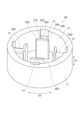
- FIG. 11 is a perspective view of a motor core according to a third embodiment.
- the motor core 6B according to the third embodiment includes an annular back yoke 10B and a plurality of teeth pieces 20 that are formed separately from the back yoke 10B and joined to the back yoke 10B.
- FIG. 12 is a perspective view of the back yoke shown in FIG. 11.
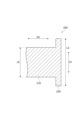
- FIG. 13 is a cross-sectional view of the motor core shown in FIG. 11.
- the back yoke 10B differs from the back yoke 10 of the first embodiment only in that it is longer in the axial direction D1 than the back yoke 10 of the first embodiment.
- the length L1 of the back yoke 10B in the axial direction D1 is longer than the length L2 of the teeth pieces 20 in the axial direction D1.
- the back yoke 10B extends to at least one side in the axial direction D1 beyond the teeth pieces 20.
- the back yoke 10B protrudes from the teeth pieces 20 to at least one side in the axial direction D1.
- the back yoke 10B extends to both sides in the axial direction D1 beyond the teeth pieces 20.
- the back yoke 10B protrudes from the teeth pieces 20 to both sides in the axial direction D1.
- the motor core 6B and the stator including the motor core 6B can be manufactured using a method similar to the manufacturing method of the motor core and the stator described above.
- the length L1 of the back yoke 10B in the axial direction D1 is longer than the length L2 of the multiple teeth pieces 20 in the axial direction D1, and the back yoke 10B extends to both sides in the axial direction D1 further than the multiple teeth pieces 20.
- a step is formed in which the back yoke 10B is higher than the multiple teeth pieces 20 in the axial direction D1, and this step increases the magnetic flux, thereby achieving a higher magnetic flux density.
- the motor core according to the fourth embodiment is basically the same as the motor core according to the second embodiment (see FIGS. 7 to 10), but differs from the motor core according to the second embodiment in that the back yoke is longer in the axial direction than the teeth pieces. For this reason, only the differences from the motor core according to the second embodiment will be described below, and descriptions of the same points as those in the motor core according to the second embodiment will be omitted.
- FIG. 14 is a perspective view of a motor core according to a fourth embodiment.
- the motor core 6C according to the fourth embodiment includes an annular back yoke 10C and a plurality of teeth pieces 20A that are formed separately from the back yoke 10C and joined to the back yoke 10C.
- FIG. 15 is a perspective view of the back yoke shown in FIG. 14.
- FIG. 16 is a cross-sectional view of the motor core shown in FIG. 14.
- the back yoke 10C differs from the back yoke 10A of the second embodiment only in that it is longer in the axial direction D1 than the back yoke 10A of the second embodiment.
- the length L3 of the back yoke 10C in the axial direction D1 is longer than the length L4 of the teeth pieces 20A in the axial direction D1.
- the back yoke 10C extends to at least one side in the axial direction D1 beyond the teeth pieces 20A.
- the back yoke 10B protrudes from the teeth pieces 20 to at least one side in the axial direction D1.
- the back yoke 10C extends to both sides in the axial direction D1 beyond the teeth pieces 20A.
- the back yoke 10B protrudes from the teeth pieces 20 to both sides in the axial direction D1.
- the motor core 6C and the stator including the motor core 6C can be manufactured using a method similar to the manufacturing method of the motor core and the stator described above.
- the length L3 of the back yoke 10C in the axial direction D1 is longer than the length L4 of the multiple teeth pieces 20A in the axial direction D1, and the back yoke 10C extends further on both sides in the axial direction D1 than the multiple teeth pieces 20A.
- a step is formed in which the back yoke 10C is higher than the multiple teeth pieces 20A in the axial direction D1, and this step increases the magnetic flux, resulting in a higher magnetic flux density.
- the motor core according to the fifth embodiment is basically the same as the motor core according to the third embodiment (see Figs. 11 to 13), but differs from the motor core according to the third embodiment in that the shapes of the body and flange of each of the multiple teeth pieces are different. Therefore, only the differences from the motor core according to the third embodiment will be described below, and descriptions of the same points as those of the motor core according to the third embodiment will be omitted.
- FIG. 17 is a perspective view of a motor core according to the fifth embodiment.
- the motor core 6D according to the fifth embodiment includes an annular back yoke 10B and a plurality of teeth pieces 20D that are formed separately from the back yoke 10B and joined to the back yoke 10B.
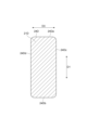
- FIG. 18 is a perspective view of the tooth piece shown in FIG. 17.
- FIGS. 19 and 20 are cross-sectional views of the tooth piece shown in FIG. 17.
- each of the multiple tooth pieces 20D has a body portion 21D that is joined to the back yoke 10B and around which the winding 7 is wound, a flange portion 22D located at the end of the body portion 21D opposite the back yoke 10B, and a base portion 23D located on the back yoke 10 side of the body portion 21.
- the base portion 23D has the same external shape as the body portion 21D.
- the body 21D has a winding surface 24D around which the winding 7 is wound.
- the winding surface 24D is the surface of the body 21D around the radial direction D2, and is the surface of the body 21D that extends from the inner peripheral surface 12 of the back yoke 10D to the flange 22D.
- the winding surface 24D has a first winding surface portion 24Da and a second winding surface portion 24Db that face the axial direction D1, and a third winding surface portion 24Dc and a fourth winding surface portion 24Dd that face the circumferential direction D3.
- the first winding surface portion 24Da and the second winding surface portion 24Db are adjacent to the third winding surface portion 24Dc on one side in the circumferential direction D3, and the first winding surface portion 24Da and the second winding surface portion 24Db are adjacent to the fourth winding surface portion 24Dd on the other side in the circumferential direction D3.
- the third winding surface portion 24Dc and the fourth winding surface portion 24Dd are adjacent to the first winding surface portion 24Da on one side in the axial direction D1
- the third winding surface portion 24Dc and the fourth winding surface portion 24Dd are adjacent to the second winding surface portion 24Db on the other side in the axial direction D1.
- first winding surface portion 24Da and the third winding surface portion 24Dc, the first winding surface portion 24Da and the fourth winding surface portion 24Dd, the second winding surface portion 24Db and the third winding surface portion 24Dc, and the second winding surface portion 24Db and the fourth winding surface portion 24Dd is connected in a curved shape.
- all of the first winding surface portion 24Da and the third winding surface portion 24Dc, the first winding surface portion 24Da and the fourth winding surface portion 24Dd, the second winding surface portion 24Db and the third winding surface portion 24Dc, and the second winding surface portion 24Db and the fourth winding surface portion 24Dd are connected in a curved shape.
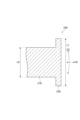
- the flange 22D differs from the flange 22 of the third embodiment only in that it is longer in the axial direction D1 than the flange 22 of the third embodiment.
- the length L5 of the flange 22D in the axial direction D1 is longer than the length L6 of the body 21D in the axial direction D1.
- the flange 22D extends to at least one side in the axial direction D1 beyond the body 21D. In other words, when viewed from the radial direction D2, the flange 22D protrudes from the body 21D to at least one side in the axial direction D1.
- the flange 22D extends to both sides in the axial direction D1 beyond the body 21D. In other words, when viewed from the radial direction D2, the flange 22D protrudes from the body 21D to both sides in the axial direction D1.
- the motor core 6D and the stator including the motor core 6D can be manufactured using a method similar to the manufacturing method of the motor core and the stator described above.
- At least one of the first winding surface portion 24Da and the third winding surface portion 24Dc, the first winding surface portion 24Da and the fourth winding surface portion 24Dd, the second winding surface portion 24Db and the third winding surface portion 24Dc, and the second winding surface portion 24Db and the fourth winding surface portion 24Dd are connected in a curved shape on the winding surface 24D of each of the multiple tooth pieces 20D, so that when the winding 7 is wound around the winding surface 24 of each of the multiple tooth pieces 20D, the winding 7 can be easily aligned along the winding surface 24D. This makes it possible to suppress the winding 7 from floating off the winding surface 24D, thereby increasing the magnetic flux density.
- the length L5 of the flange 22D in the axial direction D1 is longer than the length L6 of the body 21D in the axial direction D1, and the flange 22D extends further to at least one side in the axial direction D1 than the body 21D.
- a step is formed in which the flange 22D is higher than the body 21D in the axial direction D1, and this step increases the magnetic flux, resulting in a higher magnetic flux density.
- At least one of the first winding surface portion 24Da and the third winding surface portion 24Dc, the first winding surface portion 24Da and the fourth winding surface portion 24Dd, the second winding surface portion 24Db and the third winding surface portion 24Dc, and the second winding surface portion 24Db and the fourth winding surface portion 24Dd is connected in a curved shape on the winding surface 24D of the tooth piece 20D, so that when the winding 7 is wound around the winding surface 24D of the tooth piece 20D, the winding 7 can be easily aligned with the winding surface 24D. This makes it possible to suppress the floating of the winding 7 from the winding surface 24D, thereby increasing the magnetic flux density.
- the motor core according to the sixth embodiment is basically the same as the motor core according to the first embodiment (see FIGS. 2 to 6), but the shape of the multiple recesses in the back yoke and the shape of the body of each of the multiple teeth pieces are different from those of the motor core according to the first embodiment. Therefore, only the differences from the motor core according to the first embodiment will be described below, and descriptions of the same points as those of the motor core according to the first embodiment will be omitted.
- FIG. 21 is a perspective view of a motor core according to a sixth embodiment.
- FIG. 22 is a plan view of the motor core according to the sixth embodiment.
- the motor core 6E according to the sixth embodiment includes a circular back yoke 10E and a plurality of teeth pieces 20E that are formed separately from the back yoke 10E and joined to the back yoke 10E.
- FIG. 23 is a perspective view of the back yoke shown in FIGS. 21 and 22.
- the back yoke 10E is formed in a circular ring shape without being divided into multiple parts.
- a plurality of recesses 13E are formed on the inner peripheral surface 12E of the back yoke 10E instead of the multiple recesses 13 of the first embodiment.
- Each of the multiple recesses 13E is longer in the circumferential direction D3 than each of the multiple recesses 13 of the first embodiment. In other words, each of the multiple recesses 13E is wider than each of the multiple recesses 13 of the first embodiment.
- Figure 24 is a perspective view of the teeth piece shown in Figures 21 and 22.
- Figure 25 is a cross-sectional view of the motor core shown in Figures 21 and 22.
- each of the multiple teeth pieces 20E is fitted into each of the multiple recesses 13E formed in the inner surface 12E of the back yoke 10E.
- the multiple teeth pieces 20E are joined to the back yoke 10E so as to extend inward in the radial direction D2 from the back yoke 10E.
- Each of the multiple tooth pieces 20E has a body 21 around which the winding 7 is wound, a flange 22 located at the end of the body 21A opposite the back yoke 10, and a base 23E located on the back yoke 10E side of the body 21 (opposite the flange 22).
- Each of the multiple tooth pieces 20E is joined to the back yoke 10E by fitting the base 23E into each of multiple recesses 13E formed on the inner circumferential surface 12E of the back yoke 10E.
- the base 23E is longer in the circumferential direction D3 than the base 23 of the first embodiment. That is, the base 23E is also wider than the base 23 of the first embodiment.
- the length L7 of the base 23E in the circumferential direction D3 is longer than the length L8 of the body 21 in the circumferential direction D3.
- the base 23E extends to at least one side in the circumferential direction D3 beyond the body 21. That is, when viewed from the radial direction D2, the base 23E protrudes from the body 21 to at least one side in the circumferential direction D3.
- the base 23E extends to both sides in the circumferential direction D3 beyond the body 21. That is, when viewed from the radial direction D2, the base 23E protrudes from the body 21 to both sides in the circumferential direction D3.
- the motor core 6E and a stator including the motor core 6E can be manufactured using a method similar to the manufacturing method of the motor core and stator described above.
- the length L7 of the base 23E in the circumferential direction D3 is longer than the length L8 of the body 21 in the circumferential direction D3, and the base 23E extends beyond the body 21 to at least one side in the circumferential direction D3. This allows the multiple teeth pieces 20E to be stably joined to the back yoke 10E, and also prevents the multiple teeth pieces 20E from collapsing relative to the back yoke 10E.
- This disclosure can be used as a motor core, a stator, a teeth piece, a radial gap motor, a method for manufacturing a motor core, and a method for manufacturing a stator.
Landscapes
- Engineering & Computer Science (AREA)
- Power Engineering (AREA)
- Iron Core Of Rotating Electric Machines (AREA)
Abstract
モータコアは、ラジアルギャップモータのモータコアであって、円環状のバックヨークと、バックヨークとは別体で構成された複数のティース片と、を備え、複数のティース片は、バックヨークからバックヨークの半径方向内側に延びるようにバックヨークに接合されている。このモータコアを製造する方法は、円環状のバックヨークと、バックヨークとは別体で構成された複数のティース片と、を用意する用意工程と、複数のティース片を、バックヨークからバックヨークの半径方向内側に延びるようにバックヨークに接合する接合工程と、を備える。
Description
本発明は、モータコア、ステータ、ティース片、ラジアルギャップモータ、モータコアの製造方法、及びステータの製造方法に関する。
ラジアルギャップモータには、円環状のバックヨークから複数のティースが延びるモータコア(ステータコア)が用いられる。このようなモータコアでは、磁界を発生させるために、各ティースに巻線を巻回している。
モータコアでは、複数のティースが隣接した状態になっているため、各ティースへの巻線の巻回は、ノズル巻きと呼ばれる方法により行われている。ノズル巻きでは、巻線ノズルの先端からワイヤを繰り出しながらティースの周りで巻線ノズルを周回させることで、各ティースに巻線を巻回している。しかしながら、このようなノズル巻きでは、巻線の密度を高くするには限界があるため、磁束密度を高くすることが難しい。
そこで、複数の分割コアを接合してモータコアを製造することで、磁束密度を高める方法が考えられている(例えば、特許文献1参照)。分割コアは、円弧状のバックヨークと、バックヨークから延びる一つのティースと、により構成される。分割コアでは、ティースの周囲に障害物が存在しないため、ティースに巻線を高密度に巻回することができる。このため、各分割コアのティースに巻線を巻回した後に、複数の分割コアを接合することで、巻線が高密度に巻回されたものとなるため、て、高い磁束密度が得られ。
このようにしてモータコアを製造する際は、各分割コアのティースに巻線を巻回した後に、複数の分割コアを円環状に配置した状態で、隣接する分割コアを溶接、接着等により結合することが考えられる。しかしながら、隣接する分割コアの位置精度を極めて高くしないと、隣接する分割コア間で位置ずれが生じて、バックヨークの真円度が低いものとなる。このため、複数の分割コアを結合した後に、バックヨークの内周面及び外周面を切削してバックヨークの真円度を高める必要がある。
しかも、モータコアとして圧粉成形体が用いられることがあるが、圧粉成形体を高精度に切削することは困難であるため、上記の方法で圧粉成形体からなる複数の分割コアを接合すると、その後にバックヨークの内周面及び外周面を切削してバックヨークの真円度を高めることが困難である。
そこで、本開示は、高い磁束密度が得られるとともにバックヨークの真円度を容易に高めることができるモータコア、ステータ、ティース片、ラジアルギャップモータ、モータコアの製造方法、及びステータの製造方法を提供することを課題とする。
[1] 本開示に係るモータコアは、ラジアルギャップモータのモータコアであって、円環状のバックヨークと、バックヨークとは別体で構成された複数のティース片と、を備え、複数のティース片は、バックヨークからバックヨークの半径方向内側に延びるようにバックヨークに接合されている。
このモータコアでは、複数のティース片がバックヨークとは別体で構成されているため、複数のティース片をバックヨークに接合する前に、複数のティース片のそれぞれに巻線を巻回することができる。これにより、複数のティース片のそれぞれに巻線を高密度に巻回することができるため、高い磁束密度を得ることができる。しかも、バックヨークは、円環状に形成されているため、接合に伴う真円度の低下の問題が生じない。このため、バックヨークの真円度を容易に高めることができる。
[2] [1]に記載のモータコアにおいて、バックヨーク及び複数のティース片は、圧粉成形体であってもよい。このモータコアでは、バックヨーク及び複数のティース片が圧粉成形体であるため、高精度に切削することは困難である。しかしながら、上述したように、バックヨークは、分割されていないため、接合に伴う真円度の低下の問題が生じない。このため、バックヨークの真円度を容易に高めることができる。
[3] [1]又は[2]に記載のモータコアにおいて、バックヨークの軸線方向におけるバックヨークの長さは、軸線方向における複数のティース片の長さよりも長くてもよい。このモータコアでは、軸線方向におけるバックヨークの長さが軸線方向における複数のティース片の長さよりも長い。このため、軸線方向においてバックヨークが複数のティース片よりも高くなる段差が形成され、この段差により磁束が増加するため、より高い磁束密度を得ることができる。
[4] [1]~[3]の何れかに記載のモータコアにおいて、バックヨークは、複数のティース片よりもバックヨークの軸線方向における少なくとも一方側まで延びていてもよい。このモータコアでは、バックヨークが複数のティース片よりも軸線方向における少なくとも一方側まで延びている。このため、軸線方向においてバックヨークが複数のティース片よりも高くなる段差が形成され、この段差により磁束が増加するため、より高い磁束密度を得ることができる。
[5] [1]~[4]の何れかに記載のモータコアにおいて、複数のティース片のそれぞれは、巻線が巻回される胴部と、胴部のバックヨークとは反対側の端部に位置する鍔部と、を有し、バックヨークの軸線方向における鍔部の長さは、軸線方向における胴部の長さよりも長くてもよい。このモータコアでは、軸線方向における鍔部の長さが軸線方向における胴部の長さよりも長い。このため、軸線方向において鍔部が胴部よりも高くなる段差が形成され、この段差により磁束が増加するため、より高い磁束密度を得ることができる。
[6] [1]~[5]の何れかに記載のモータコアにおいて、複数のティース片のそれぞれは、巻線が巻回される胴部と、胴部のバックヨークとは反対側の端部に位置する鍔部と、を有し、鍔部は、胴部よりもバックヨークの軸線方向における少なくとも一方側まで延びていてもよい。このモータコアでは、鍔部が胴部よりも軸線方向における少なくとも一方側まで延びている。このため、軸線方向において鍔部が胴部よりも高くなる段差が形成され、この段差により磁束が増加するため、より高い磁束密度を得ることができる。
[7] [1]~[6]の何れかに記載のモータコアにおいて、バックヨークは、バックヨークの内周面に形成された複数の凹部を有し、複数のティース片のそれぞれは、複数の凹部のそれぞれに嵌め込まれていてもよい。このモータコアでは、バックヨークの内周面に形成された複数の凹部のそれぞれに、複数のティース片のそれぞれが嵌め込まれているため、バックヨークと複数のティース片との接合強度を高めることができるとともに、バックヨークに対する複数のティース片の位置精度を高めることができる。
[8] [7]に記載のモータコアにおいて、複数のティース片のそれぞれは、複数の凹部のそれぞれに嵌め込まれる凸部を有してもよい。このモータコアでは、複数のティース片のそれぞれの凸部が、バックヨークの内周面に形成された複数の凹部のそれぞれに嵌め込まれているため、バックヨークと複数のティース片との接合強度を高めることができるとともに、バックヨークに対する複数のティース片の位置精度を高めることができる。
[9] [8]に記載のモータコアにおいて、凹部は、蟻みぞであり、凸部は、蟻ほぞであってもよい。このモータコアでは、凹部が蟻みぞであり、凸部が蟻ほぞであるため、バックヨークから複数のティース片が抜けるのを抑制して、バックヨークと複数のティース片との接合強度を高めることができる。
[10] [7]に記載のモータコアにおいて、複数のティース片のそれぞれは、巻線が巻回される胴部と、胴部のバックヨーク側に位置して複数の凹部のそれぞれに嵌め込まれる基部と、を有し、バックヨークの周方向における基部の長さは、周方向における胴部の長さよりも長くてもよい。このモータコアでは、周方向における基部の長さが周方向における胴部の長さよりも長いため、バックヨークに対して複数のティース片を安定的に接合することができるとともに、バックヨークに対して複数のティース片が倒れるのを抑制することができる。
[11] [7]又は[10]に記載のモータコアにおいて、複数のティース片のそれぞれは、巻線が巻回される胴部と、胴部のバックヨーク側に位置して複数の凹部のそれぞれに嵌め込まれる基部と、を有し、基部は、胴部よりもバックヨークの周方向における少なくとも一方側まで延びていてもよい。このモータコアでは、基部が胴部よりも周方向における少なくとも一方側まで延びているため、バックヨークに対して複数のティース片を安定的に接合することができるとともに、バックヨークに対して複数のティース片が倒れるのを抑制することができる。
[12] [1]~[11]の何れかに記載のモータコアにおいて、複数のティース片のそれぞれは、巻線が巻回される巻回面を有し、巻回面は、バックヨークの軸線方向に対向する第一巻回面部及び第二巻回面部と、バックヨークの周方向に対向する第三巻回面部及び第四巻回面部と、を有し、第一巻回面部と第三巻回面部、第一巻回面部と第四巻回面部、第二巻回面部と第三巻回面部、及び第二巻回面部と第四巻回面部の少なくとも一つは、曲面状に接続されていてもよい。このモータコアでは、複数のティース片のそれぞれの巻回面において、第一巻回面部と第三巻回面部、第一巻回面部と第四巻回面部、第二巻回面部と第三巻回面部、及び第二巻回面部と第四巻回面部の少なくとも一つが、曲面状に接続されているため、複数のティース片のそれぞれの巻回面に巻線を巻回した際に、巻線を巻回面に沿わせ易くなる。これにより、巻線の巻回面からの浮きを抑制することができるため、磁束密度を高めることができる。
[13] 本開示に係るティース片は、円環状のバックヨークに接合されることで[1]~[12]の何れかのモータコアをなす。
このティース片では、円環状のバックヨークに接合されることで上述したモータコアをなすため、バックヨークに接合する前に巻線を巻回することができる。これにより、ティース片に巻線を高密度に巻回することができるため、高い磁束密度を得ることができる。しかも、ティース片を接合するバックヨークは、分割されている必要がないため、接合に伴う真円度の低下の問題が生じない。このため、バックヨークの真円度を容易に高めることができる。
[14] [13]に記載のティース片において、巻線が巻回される巻回面を有し、巻回面は、互いに対向する第一巻回面部及び第二巻回面部と、第一巻回面部及び第二巻回面部と隣接する第三巻回面部及び第四巻回面部と、を有し、第一巻回面部と第三巻回面部、第一巻回面部と第四巻回面部、第二巻回面部と第三巻回面部、及び第二巻回面部と第四巻回面部の少なくとも一つは、曲面状に接続されていてもよい。このティース片では、巻回面において、第一巻回面部と第三巻回面部、第一巻回面部と第四巻回面部、第二巻回面部と第三巻回面部、及び第二巻回面部と第四巻回面部の少なくとも一つが、曲面状に接続されているため、ティース片の巻回面に巻線を巻回した際に、巻線を巻回面に沿わせ易くなる。これにより、巻線の巻回面からの浮きを抑制することができるため、磁束密度を高めることができる。
[15] 本開示に係るステータは、ラジアルギャップモータのステータであって、[1]~[12]の何れかに記載のモータコアと、モータコアの複数のティース片のそれぞれに巻回された巻線と、を備える。このステータでは、上述したモータコアを備えるため、高い磁束密度が得られるとともにバックヨークの真円度を容易に高めることができる。
[16] 本開示に係るラジアルギャップモータは、[15]に記載されたステータと、ステータに対して回転可能に配置されたロータと、を備える。このラジアルギャップモータでは、上述したステータを備えるため、高い磁束密度が得られるとともにバックヨークの真円度を容易に高めることができる。
[17] 本開示に係るモータコアの製造方法は、[1]~[12]の何れかに記載のモータコアを製造するモータコアの製造方法であって、円環状のバックヨークと、バックヨークとは別体で構成された複数のティース片と、を用意する用意工程と、複数のティース片を、バックヨークからバックヨークの半径方向内側に延びるようにバックヨークに接合する接合工程と、を備える。
このモータコアの製造方法では、バックヨークとは別体で構成された複数のティース片をバックヨークに接合するため、複数のティース片をバックヨークに接合する前に、複数のティース片のそれぞれに巻線を巻回することができる。これにより、複数のティース片のそれぞれに巻線を高密度に巻回することができるため、高い磁束密度を得ることができる。しかも、バックヨークは、円環状に形成されているため、接合に伴う真円度の低下の問題が生じない。このため、バックヨークの真円度を容易に高めることができる。
[18] 本開示に係るステータの製造方法は、[15]に記載されたステータを製造するステータの製造方法であって、円環状のバックヨークと、バックヨークとは別体で構成された複数のティース片と、を用意する用意工程と、複数のティース片のそれぞれに巻線を巻回する巻回工程と、巻回工程の後、複数のティース片を、バックヨークからバックヨークの半径方向内側に延びるようにバックヨークに接合する接合工程と、を備える。
このステータの製造方法では、バックヨークとは別体で構成された複数のティース片をバックヨークに接合する前に、複数のティース片のそれぞれに巻線を巻回する。これにより、複数のティース片のそれぞれに巻線を高密度に巻回することができるため、高い磁束密度を得ることができる。しかも、バックヨークは、円環状に形成されているため、接合に伴う真円度の低下の問題が生じない。このため、バックヨークの真円度を容易に高めることができる。
高い磁束密度が得られるとともにバックヨークの真円度を容易に高めることができる。
以下、図面を参照しながら本開示の好適な実施形態について詳細に説明する。なお、図面中、同一又は相当部分には同一符号を付し、重複する説明は省略する。また、図面では、説明を分かり易くするために、寸法割合等を適宜変更している。
[ラジアルギャップモータ]
図1は、実施形態に係るラジアルギャップモータの模式断面である。図1に示すように、本実施形態に係るラジアルギャップモータ1は、ステータ2と、ステータ2に対して回転可能に配置されたロータ3と、ロータ3に固定されたシャフト4と、を備える。ステータ2とロータ3とは、シャフト4の半径方向に離間して配置されている。ロータ3の中央部には、シャフト4が挿通されるシャフト用孔5が形成されている。
図1は、実施形態に係るラジアルギャップモータの模式断面である。図1に示すように、本実施形態に係るラジアルギャップモータ1は、ステータ2と、ステータ2に対して回転可能に配置されたロータ3と、ロータ3に固定されたシャフト4と、を備える。ステータ2とロータ3とは、シャフト4の半径方向に離間して配置されている。ロータ3の中央部には、シャフト4が挿通されるシャフト用孔5が形成されている。
[ステータ]
本実施形態に係るステータ2は、ラジアルギャップモータ1のステータである。ステータ2は、モータコア6と、モータコア6に巻回された巻線7と、を備える。モータコア6は、ステータ2から巻線7を除いた部分であり、ステータコアとも呼ばれる。
本実施形態に係るステータ2は、ラジアルギャップモータ1のステータである。ステータ2は、モータコア6と、モータコア6に巻回された巻線7と、を備える。モータコア6は、ステータ2から巻線7を除いた部分であり、ステータコアとも呼ばれる。
[第一実施形態のモータコア]
図2は、第一実施形態に係るモータコアの斜視図である。図3は、第一実施形態に係るモータコアの平面図である。図1~図3に示すように、本実施形態に係るモータコア6は、円環状のバックヨーク10と、バックヨーク10とは別体で構成されてバックヨーク10に接合された複数のティース片20と、を備える。本実施形態では、モータコア6は、4つのティース片20を備えるものとして説明するが、ティース片20の数は、2以上であれば特に限定されるものではない。
図2は、第一実施形態に係るモータコアの斜視図である。図3は、第一実施形態に係るモータコアの平面図である。図1~図3に示すように、本実施形態に係るモータコア6は、円環状のバックヨーク10と、バックヨーク10とは別体で構成されてバックヨーク10に接合された複数のティース片20と、を備える。本実施形態では、モータコア6は、4つのティース片20を備えるものとして説明するが、ティース片20の数は、2以上であれば特に限定されるものではない。
図4は、図2及び図3に示すバックヨークの斜視図である。図1~図4に示すように、バックヨーク10は、複数に分割されることなく、円環状に形成されている。ここで、バックヨーク10の軸線方向を軸線方向D1といい、バックヨーク10の半径方向を半径方向D2といい、バックヨーク10の周方向を周方向D3という。軸線方向D1は、バックヨーク10の厚み方向(ラジアルギャップモータ1におけるロータ3の回転軸線方向)でもある。半径方向D2は、バックヨーク10がなす円環の半径方向(ラジアルギャップモータ1におけるロータ3の半径方向)でもある。周方向D3は、バックヨーク10がなす円環の周方向(ラジアルギャップモータ1におけるロータ3の回転方向)でもある。
バックヨーク10の外周面11は、真円状に形成されている。なお、真円状には、完全な真円の形状だけでなく、製造誤差等により変形した略真円の形状も含まれる。バックヨーク10の内周面12は、真円状に形成されていてもよく、バックヨーク10に複数のティース片20を接合しやすくするために多角形であってもよい。
バックヨーク10の内周面12には、複数の凹部13が形成されている。複数の凹部13は、周方向D3において等間隔に位置している。複数の凹部13の数は、複数のティース片20の数と同じである。複数の凹部13のそれぞれは、バックヨーク10の内周面12から半径方向D2における外側に向かって延びているとともに、バックヨーク10を軸線方向D1に貫通している。
バックヨーク10は、例えば、絶縁材で被覆された軟質磁性粉末がプレスされてなる圧粉成形体である。圧粉成形体であるバックヨーク10は、例えば、市販の圧粉成形装置により成形することができる。軟質磁性粉末の素材は、例えば、純鉄、鉄シリコン、鉄コバルトである。軟質磁性粉末の平均粒径は、例えば、3μm以上300μm以下、30μm以上200μm以下、又は50μm以上150μm以下である。絶縁材の素材は、例えば、リン酸、シリコーン等を含む絶縁被膜である。なお、軟質磁性粉末の平均粒径は、株式会社セイシン企業製のロボットシフター(型番:RPS-205)により計測される。なお、バックヨーク10は、複数枚の電磁鋼板が積層された積層体であってもよい。
図5は、図2及び図3に示すティース片の斜視図である。図6は、図2及び図3に示すティース片の断面図である。図1~図6に示すように、複数のティース片20は、円環状のバックヨーク10に接合されることで、モータコア6をなす。複数のティース片20のそれぞれは、巻線7が巻回される部分である。複数のティース片20のそれぞれは、バックヨーク10の内周面12に形成された複数の凹部13のそれぞれに嵌め込まれている。そして、複数のティース片20は、バックヨーク10から半径方向D2内側に延びるようにバックヨーク10に接合されている。
複数のティース片20のそれぞれは、巻線7が巻回される胴部21と、胴部21のバックヨーク10とは反対側の端部に位置する鍔部22と、胴部21のバックヨーク10側(鍔部22とは反対側)に位置する基部23と、を有する。複数のティース片20のそれぞれは、基部23がバックヨーク10の内周面12に形成された複数の凹部13のそれぞれに嵌め込まれて、バックヨーク10に接合されている。胴部21及び基部23は、半径方向D2に直線状に延びている。胴部21及び基部23の半径方向D2と直交する方向の断面形状は、例えば、矩形状である。
胴部21は、巻線7が巻回される巻回面24を有する。巻回面24は、胴部21の半径方向D2周りの表面であるとともに、バックヨーク10の内周面12から鍔部22に至る胴部21の表面である。巻回面24は、軸線方向D1に対向する第一巻回面部24a及び第二巻回面部24bと、周方向D3に対向する第三巻回面部24c及び第四巻回面部24dと、を有する。第一巻回面部24a及び第二巻回面部24bは、周方向D3における一方側において、第三巻回面部24cと隣接しており、第一巻回面部24a及び第二巻回面部24bは、周方向D3における他方側において、第四巻回面部24dと隣接している。また、第三巻回面部24c及び第四巻回面部24dは、軸線方向D1における一方側において、第一巻回面部24aと隣接しており、第三巻回面部24c及び第四巻回面部24dは、軸線方向D1における他方側において、第二巻回面部24bと隣接している。
鍔部22は、ステータ2及びモータコア6の内周面を形成する。鍔部22の周方向D3における長さは、胴部21の周方向D3における長さよりも長くなっている。そして、鍔部22は、胴部21よりも周方向D3における少なくとも一方側まで延びている。つまり、半径方向D2から見た場合に、鍔部22は、胴部21から周方向D3における少なくとも一方側に突出している。本実施形態では、鍔部22は、胴部21よりも周方向D3における両側まで延びている。つまり、半径方向D2から見た場合に、鍔部22は、胴部21から周方向D3における両側に突出している。
複数のティース片20は、例えば、絶縁材で被覆された軟質磁性粉末がプレスされてなる圧粉成形体である。圧粉成形体である複数のティース片20は、例えば、市販の圧粉成形装置により成形することができる。軟質磁性粉末の素材は、例えば、純鉄、鉄シリコン、鉄コバルトである。軟質磁性粉末の平均粒径は、例えば、3μm以上300μm以下、30μm以上200μm以下、又は50μm以上150μm以下である。絶縁材の素材は、例えば、リン酸、シリコーン等を含む絶縁被膜である。なお、軟質磁性粉末の平均粒径は、株式会社セイシン企業製のロボットシフター(型番:RPS-205)により計測される。なお、複数のティース片20は、複数枚の電磁鋼板が積層された積層体であってもよい。
[モータコア及びステータの製造方法]
次に、本実施形態に係るモータコア及びステータの製造方法について説明する。この製造方法は、上述したモータコア6及びステータ2を製造する方法である。
次に、本実施形態に係るモータコア及びステータの製造方法について説明する。この製造方法は、上述したモータコア6及びステータ2を製造する方法である。
モータコア及びステータの製造方法は、用意工程と、巻回工程と、接合工程と、を備える。
用意工程では、円環状のバックヨーク10と、バックヨーク10とは別体で構成された複数のティース片20と、を用意する。
巻回工程は、接合工程の前であれば任意のタイミングで行うことができる。例えば、巻回工程は、用意工程の前に行ってもよく、用意工程の後に行ってもよく、用意工程と同時に行ってもよい。巻回工程では、複数のティース片20のそれぞれに巻線7を巻回する。複数のティース片20のそれぞれに対する巻線7の巻回は、例えば、ティース片20を回転させてティース片20の巻回面24に巻線7を巻回させるスピンドル巻き、ノズル巻き、フライヤー巻き等により行うことができる。
接合工程は、用意工程及び巻回工程の後に行う。接合工程では、複数のティース片20のそれぞれを、バックヨーク10の内周面12に形成された複数の凹部13のそれぞれに嵌め込む。そして、複数のティース片20がバックヨーク10から半径方向D2内側に延びるように、複数のティース片20をバックヨーク10に接合する。バックヨーク10に対する複数のティース片20の接合は、例えば、溶接、接着等により行うことができる。
これにより、モータコア6及びステータ2の製造が終了する。なお、上記の巻回工程を行わないことで、巻線7を有しないモータコア6のみを製造することができる。
以上説明したように、本実施形態に係るモータコア6では、複数のティース片20がバックヨーク10とは別体で構成されているため、複数のティース片20をバックヨーク10に接合する前に、複数のティース片20のそれぞれに巻線7を巻回することができる。これにより、複数のティース片20のそれぞれに巻線を高密度に巻回することができるため、高い磁束密度を得ることができる。しかも、バックヨーク10は、円環状に形成されているため、接合に伴う真円度の低下の問題が生じない。このため、バックヨーク10の真円度を容易に高めることができる。
また、このモータコア6では、バックヨーク10及び複数のティース片20が圧粉成形体であるため、高精度に切削することは困難である。しかしながら、上述したように、バックヨーク10は、分割されていないため、接合に伴う真円度の低下の問題が生じない。このため、バックヨーク10の真円度を容易に高めることができる。
また、このモータコア6では、バックヨーク10の内周面12に形成された複数の凹部13のそれぞれに、複数のティース片20のそれぞれが嵌め込まれているため、バックヨーク10と複数のティース片20との接合強度を高めることができるとともに、バックヨーク10に対する複数のティース片20の位置精度を高めることができる。
本実施形態に係るティース片20では、円環状のバックヨーク10に接合されることで上述したモータコア6をなすため、バックヨーク10に接合する前に巻線7を巻回することができる。これにより、ティース片20に巻線7を高密度に巻回することができるため、高い磁束密度を得ることができる。しかも、ティース片20を接合するバックヨーク10は、分割されている必要がないため、接合に伴う真円度の低下の問題が生じない。このため、バックヨーク10の真円度を容易に高めることができる。
本実施形態に係るステータ2では、上述したモータコア6を備えるため、高い磁束密度が得られるとともにバックヨーク10の真円度を容易に高めることができる。
本実施形態に係るラジアルギャップモータ1では、上述したステータ2を備えるため、高い磁束密度が得られるとともにバックヨーク10の真円度を容易に高めることができる。
本実施形態に係るモータコアの製造方法では、バックヨーク10とは別体で構成された複数のティース片20をバックヨーク10に接合するため、複数のティース片20をバックヨーク10に接合する前に、複数のティース片20のそれぞれに巻線7を巻回することができる。これにより、複数のティース片20のそれぞれに巻線を高密度に巻回することができるため、高い磁束密度を得ることができる。しかも、バックヨーク10は、円環状に形成されているため、接合に伴う真円度の低下の問題が生じない。このため、バックヨーク10の真円度を容易に高めることができる。
本実施形態に係るステータの製造方法では、バックヨーク10とは別体で構成された複数のティース片20をバックヨーク10に接合する前に、複数のティース片20のそれぞれに巻線7を巻回する。これにより、複数のティース片20のそれぞれに巻線7を高密度に巻回することができるため、高い磁束密度を得ることができる。しかも、バックヨーク10は、円環状に形成されているため、接合に伴う真円度の低下の問題が生じない。このため、バックヨーク10の真円度を容易に高めることができる。
[第二実施形態のモータコア]
次に、第二実施形態に係るモータコアについて説明する。第二実施形態に係るモータコアは、基本的に第一実施形態に係るモータコア(図2~図6参照)と同様であるが、バックヨークと複数のティース片との接合構造が第一実施形態に係るモータコアと相違する。このため、以下では、第一実施形態に係るモータコアと相違する事項のみ説明し、第一実施形態に係るモータコアと同様の事項の説明を省略する。
次に、第二実施形態に係るモータコアについて説明する。第二実施形態に係るモータコアは、基本的に第一実施形態に係るモータコア(図2~図6参照)と同様であるが、バックヨークと複数のティース片との接合構造が第一実施形態に係るモータコアと相違する。このため、以下では、第一実施形態に係るモータコアと相違する事項のみ説明し、第一実施形態に係るモータコアと同様の事項の説明を省略する。
図7は、第二実施形態に係るモータコアの斜視図である。図8は、第二実施形態に係るモータコアの平面図である。図7及び図8に示すように、第二実施形態に係るモータコア6Aは、円環状のバックヨーク10Aと、バックヨーク10Aとは別体で構成されてバックヨーク10Aに接合された複数のティース片20Aと、を備える。
図9は、図7及び図8に示すバックヨークの斜視図である。図7~図9に示すように、バックヨーク10Aは、複数に分割されることなく、円環状に形成されている。バックヨーク10Aの内周面12Aには、第一実施形態の複数の凹部13の代わりに複数の凹部13Aが形成されている。複数の凹部13Aのそれぞれは、第一実施形態の複数の凹部13のそれぞれよりも周方向D3において短くなっている。つまり、複数の凹部13Aのそれぞれは、第一実施形態の複数の凹部13のそれぞれよりも幅狭になっている。また、複数の凹部13Aのそれぞれは、例えば、蟻みぞである。複数の凹部13Aのそれぞれが蟻みぞであるとは、例えば、複数の凹部13Aのそれぞれが、半径方向D2外側(外周面11側)に向かって広がる三角形状に形成されていること、内周面12Aから外周面11に向かうに従い周方向D3の幅が広がる部分を有していること、周方向D3よりも半径方向D2外側(外周面11側)に向かう面を有すること等をいう。
図10は、図7及び図8に示すティース片の斜視図である。図7~図10に示すように、複数のティース片20Aのそれぞれは、バックヨーク10Aの内周面12Aに形成された複数の凹部13Aのそれぞれに嵌め込まれている。そして、複数のティース片20Aは、バックヨーク10Aから半径方向D2内側に延びるようにバックヨーク10Aに接合されている。
複数のティース片20Aのそれぞれは、巻線7が巻回される胴部21と、胴部21Aのバックヨーク10Aとは反対側の端部に位置する鍔部22と、胴部21Aのバックヨーク10側(鍔部22とは反対側)に位置する凸部23Aと、を有する。複数のティース片20Aのそれぞれは、凸部23Aがバックヨーク10Aの内周面12Aに形成された複数の凹部13Aのそれぞれに嵌め込まれて、バックヨーク10Aに接合されている。凸部23Aは、複数の凹部のそれぞれに対応する蟻ほぞである。凸部23Aが蟻ほぞであるとは、例えば、凸部23Aが、半径方向D2外側(外周面11側)に向かって広がる三角形状に形成されていること、突出先端に向かうに従い周方向D3の幅が広がる部分を有していること、周方向D3よりも半径方向D2外側に向かう面を有すること等をいう。
バックヨーク10Aの内周面12Aに形成された複数の凹部13Aのそれぞれに対する、複数のティース片20Aのそれぞれの凸部23Aの嵌め込みは、例えば、複数の凹部13Aのそれぞれの軸線方向D1における一方側の開口から、複数のティース片20Aのそれぞれの凸部23Aを挿入し、バックヨーク10Aに対して複数のティース片20Aのそれぞれを軸線方向D1にスライドさせることにより行うことができる。
なお、モータコア6A及びモータコア6Aを備えるステータの製造は、上述したモータコア及びステータの製造方法と同様の方法により行うことができる。
以上説明したように、本実施形態に係るモータコア6Aでは、複数のティース片20Aのそれぞれの凸部23Aが、バックヨーク10Aの内周面12Aに形成された複数の凹部13Aに嵌め込まれているため、バックヨーク10Aと複数のティース片20Aとの接合強度を高めることができるとともに、バックヨーク10Aに対する複数のティース片20Aの位置精度を高めることができる。
また、このモータコア6Aでは、バックヨーク10Aの内周面12Aに形成された複数の凹部13Aのそれぞれが蟻みぞであり、複数のティース片20Aのそれぞれの凸部23Aが蟻ほぞであるため、バックヨーク10Aから複数のティース片20Aが抜けるのを抑制して、バックヨーク10Aと複数のティース片20Aとの接合強度を高めることができる。
[第三実施形態のモータコア]
次に、第三実施形態に係るモータコアについて説明する。第三実施形態に係るモータコアは、基本的に第一実施形態に係るモータコア(図2~図6参照)と同様であるが、バックヨークが複数のティース片よりも軸線方向に長い点において第一実施形態に係るモータコアと相違する。このため、以下では、第一実施形態に係るモータコアと相違する事項のみ説明し、第一実施形態に係るモータコアと同様の事項の説明を省略する。
次に、第三実施形態に係るモータコアについて説明する。第三実施形態に係るモータコアは、基本的に第一実施形態に係るモータコア(図2~図6参照)と同様であるが、バックヨークが複数のティース片よりも軸線方向に長い点において第一実施形態に係るモータコアと相違する。このため、以下では、第一実施形態に係るモータコアと相違する事項のみ説明し、第一実施形態に係るモータコアと同様の事項の説明を省略する。
図11は、第三実施形態に係るモータコアの斜視図である。図11に示すように第三実施形態に係るモータコア6Bは、円環状のバックヨーク10Bと、バックヨーク10Bとは別体で構成されてバックヨーク10Bに接合された複数のティース片20と、を備える。
図12は、図11に示すバックヨークの斜視図である。図13は、図11に示すモータコアの断面図である。図11~図13に示すように、バックヨーク10Bは、第一実施形態のバックヨーク10よりも軸線方向D1に長い点のみ、第一実施形態のバックヨーク10と相違する。軸線方向D1におけるバックヨーク10Bの長さL1は、軸線方向D1における複数のティース片20の長さL2よりも長い。そして、バックヨーク10Bは、複数のティース片20よりも軸線方向D1における少なくとも一方側まで延びている。つまり、半径方向D2から見た場合に、バックヨーク10Bは、複数のティース片20から軸線方向D1における少なくとも一方側に突出している。本実施形態では、バックヨーク10Bは、複数のティース片20よりも軸線方向D1における両側まで延びている。つまり、半径方向D2から見た場合に、バックヨーク10Bは、複数のティース片20から軸線方向D1における両側に突出している。
なお、モータコア6B及びモータコア6Bを備えるステータの製造は、上述したモータコア及びステータの製造方法と同様の方法により行うことができる。
以上説明したように、本実施形態に係るモータコア6Bでは、軸線方向D1におけるバックヨーク10Bの長さL1が軸線方向D1における複数のティース片20の長さL2よりも長く、バックヨーク10Bが複数のティース片20よりも軸線方向D1における両側まで延びている。このため、軸線方向D1においてバックヨーク10Bが複数のティース片20よりも高くなる段差が形成され、この段差により磁束が増加するため、より高い磁束密度を得ることができる。
[第四実施形態のモータコア]
次に、第四実施形態に係るモータコアについて説明する。第四実施形態に係るモータコアは、基本的に第二実施形態に係るモータコア(図7~図10参照)と同様であるが、バックヨークが複数のティース片よりも軸線方向に長い点において第二実施形態に係るモータコアと相違する。このため、以下では、第二実施形態に係るモータコアと相違する事項のみ説明し、第二実施形態に係るモータコアと同様の事項の説明を省略する。
次に、第四実施形態に係るモータコアについて説明する。第四実施形態に係るモータコアは、基本的に第二実施形態に係るモータコア(図7~図10参照)と同様であるが、バックヨークが複数のティース片よりも軸線方向に長い点において第二実施形態に係るモータコアと相違する。このため、以下では、第二実施形態に係るモータコアと相違する事項のみ説明し、第二実施形態に係るモータコアと同様の事項の説明を省略する。
図14は、第四実施形態に係るモータコアの斜視図である。図14に示すように第四実施形態に係るモータコア6Cは、円環状のバックヨーク10Cと、バックヨーク10Cとは別体で構成されてバックヨーク10Cに接合された複数のティース片20Aと、を備える。
図15は、図14に示すバックヨークの斜視図である。図16は、図14に示すモータコアの断面図である。図14~図16に示すように、バックヨーク10Cは、第二実施形態のバックヨーク10Aよりも軸線方向D1に長い点のみ、第二実施形態のバックヨーク10Aと相違する。軸線方向D1におけるバックヨーク10Cの長さL3は、軸線方向D1における複数のティース片20Aの長さL4よりも長い。そして、バックヨーク10Cは、複数のティース片20Aよりも軸線方向D1における少なくとも一方側まで延びている。つまり、半径方向D2から見た場合に、バックヨーク10Bは、複数のティース片20から軸線方向D1における少なくとも一方側に突出している。本実施形態では、バックヨーク10Cは、複数のティース片20Aよりも軸線方向D1における両側まで延びている。つまり、半径方向D2から見た場合に、バックヨーク10Bは、複数のティース片20から軸線方向D1における両側に突出している。
なお、モータコア6C及びモータコア6Cを備えるステータの製造は、上述したモータコア及びステータの製造方法と同様の方法により行うことができる。
以上説明したように、本実施形態に係るモータコア6Cでは、軸線方向D1におけるバックヨーク10Cの長さL3が軸線方向D1における複数のティース片20Aの長さL4よりも長く、バックヨーク10Cが複数のティース片20Aよりも軸線方向D1における両側まで延びている。このため、軸線方向D1においてバックヨーク10Cが複数のティース片20Aよりも高くなる段差が形成され、この段差により磁束が増加するため、より高い磁束密度を得ることができる。
[第五実施形態のモータコア]
次に、第五実施形態に係るモータコアについて説明する。第五実施形態に係るモータコアは、基本的に第三実施形態に係るモータコア(図11~図13参照)と同様であるが、複数のティース片のそれぞれの胴部及び鍔部の形状が異なる点において第三実施形態に係るモータコアと相違する。このため、以下では、第三実施形態に係るモータコアと相違する事項のみ説明し、第三実施形態に係るモータコアと同様の事項の説明を省略する。
次に、第五実施形態に係るモータコアについて説明する。第五実施形態に係るモータコアは、基本的に第三実施形態に係るモータコア(図11~図13参照)と同様であるが、複数のティース片のそれぞれの胴部及び鍔部の形状が異なる点において第三実施形態に係るモータコアと相違する。このため、以下では、第三実施形態に係るモータコアと相違する事項のみ説明し、第三実施形態に係るモータコアと同様の事項の説明を省略する。
図17は、第五実施形態に係るモータコアの斜視図である。図17に示すように第五実施形態に係るモータコア6Dは、円環状のバックヨーク10Bと、バックヨーク10Bとは別体で構成されてバックヨーク10Bに接合された複数のティース片20Dと、を備える。
図18は、図17に示すティース片の斜視図である。図19及び図20は、図17に示すティース片の断面図である。図17~図20に示すように、複数のティース片20Dのそれぞれは、バックヨーク10Bに接合されて巻線7が巻回される胴部21Dと、胴部21Dのバックヨーク10Bとは反対側の端部に位置する鍔部22Dと、胴部21のバックヨーク10側に位置する基部23Dと、を有する。基部23Dは、胴部21Dと同様の外形をなしている。
胴部21Dは、巻線7が巻回される巻回面24Dを有する。巻回面24Dは、胴部21Dの半径方向D2周りの表面であるとともに、バックヨーク10Dの内周面12から鍔部22Dに至る胴部21Dの表面である。巻回面24Dは、軸線方向D1に対向する第一巻回面部24Da及び第二巻回面部24Dbと、周方向D3に対向する第三巻回面部24Dc及び第四巻回面部24Ddと、を有する。第一巻回面部24Da及び第二巻回面部24Dbは、周方向D3における一方側において、第三巻回面部24Dcと隣接しており、第一巻回面部24Da及び第二巻回面部24Dbは、周方向D3における他方側において、第四巻回面部24Ddと隣接している。また、第三巻回面部24Dc及び第四巻回面部24Ddは、軸線方向D1における一方側において、第一巻回面部24Daと隣接しており、第三巻回面部24Dc及び第四巻回面部24Ddは、軸線方向D1における他方側において、第二巻回面部24Dbと隣接している。
そして、第一巻回面部24Daと第三巻回面部24Dc、第一巻回面部24Daと第四巻回面部24Dd、第二巻回面部24Dbと第三巻回面部24Dc、及び第二巻回面部24Dbと第四巻回面部24Ddの少なくとも一つは、曲面状に接続されている。本実施形態では、第一巻回面部24Daと第三巻回面部24Dc、第一巻回面部24Daと第四巻回面部24Dd、第二巻回面部24Dbと第三巻回面部24Dc、及び第二巻回面部24Dbと第四巻回面部24Ddの全てが、曲面状に接続されている。
鍔部22Dは、第三実施形態の鍔部22よりも軸線方向D1に長い点のみ、第三実施形態の鍔部22と相違する。軸線方向D1における鍔部22Dの長さL5は、軸線方向D1における胴部21Dの長さL6よりも長い。そして、鍔部22Dは、胴部21Dよりも軸線方向D1における少なくとも一方側まで延びている。つまり、半径方向D2から見た場合に、鍔部22Dは、胴部21Dから軸線方向D1における少なくとも一方側に突出している。本実施形態では、鍔部22Dは、胴部21Dよりも軸線方向D1における両側まで延びている。つまり、半径方向D2から見た場合に、鍔部22Dは、胴部21Dから軸線方向D1における両側に突出している。
なお、モータコア6D及びモータコア6Dを備えるステータの製造は、上述したモータコア及びステータの製造方法と同様の方法により行うことができる。
以上説明したように、本実施形態に係るモータコア6Dでは、複数のティース片20Dのそれぞれの巻回面24Dにおいて、第一巻回面部24Daと第三巻回面部24Dc、第一巻回面部24Daと第四巻回面部24Dd、第二巻回面部24Dbと第三巻回面部24Dc、及び第二巻回面部24Dbと第四巻回面部24Ddの少なくとも一つが、曲面状に接続されているため、複数のティース片20Dのそれぞれの巻回面24に巻線7を巻回した際に、巻線7を巻回面24Dに沿わせ易くなる。これにより、巻線7の巻回面24Dからの浮きを抑制することができるため、磁束密度を高めることができる。
また、このモータコア6Dでは、軸線方向D1における鍔部22Dの長さL5が軸線方向D1における胴部21Dの長さL6よりも長く、鍔部22Dが胴部21Dよりも軸線方向D1における少なくとも一方側まで延びている。このため、軸線方向D1において鍔部22Dが胴部21Dよりも高くなる段差が形成され、この段差により磁束が増加するため、より高い磁束密度を得ることができる。
本実施形態に係るティース片20Dでは、巻回面24において、第一巻回面部24Daと第三巻回面部24Dc、第一巻回面部24Daと第四巻回面部24Dd、第二巻回面部24Dbと第三巻回面部24Dc、及び第二巻回面部24Dbと第四巻回面部24Ddの少なくとも一つが、曲面状に接続されているため、ティース片20Dの巻回面24Dに巻線7を巻回した際に、巻線7を巻回面24Dに沿わせ易くなる。これにより、巻線7の巻回面24Dからの浮きを抑制することができるため、磁束密度を高めることができる。
[第六実施形態のモータコア]
次に、第六実施形態に係るモータコアについて説明する。第六実施形態に係るモータコアは、基本的に第一実施形態に係るモータコア(図2~図6参照)と同様であるが、バックヨークの複数の凹部の形状及び複数のティース片のそれぞれの胴部の形状が第一実施形態に係るモータコアと相違する。このため、以下では、第一実施形態に係るモータコアと相違する事項のみ説明し、第一実施形態に係るモータコアと同様の事項の説明を省略する。
次に、第六実施形態に係るモータコアについて説明する。第六実施形態に係るモータコアは、基本的に第一実施形態に係るモータコア(図2~図6参照)と同様であるが、バックヨークの複数の凹部の形状及び複数のティース片のそれぞれの胴部の形状が第一実施形態に係るモータコアと相違する。このため、以下では、第一実施形態に係るモータコアと相違する事項のみ説明し、第一実施形態に係るモータコアと同様の事項の説明を省略する。
図21は、第六実施形態に係るモータコアの斜視図である。図22は、第六実施形態に係るモータコアの平面図である。図21及び図22に示すように、第六実施形態に係るモータコア6Eは、円環状のバックヨーク10Eと、バックヨーク10Eとは別体で構成されてバックヨーク10Eに接合された複数のティース片20Eと、を備える。
図23は、図21及び図22に示すバックヨークの斜視図である。図21~図23に示すように、バックヨーク10Eは、複数に分割されることなく、円環状に形成されている。バックヨーク10Eの内周面12Eには、第一実施形態の複数の凹部13の代わりに複数の凹部13Eが形成されている。複数の凹部13Eのそれぞれは、第一実施形態の複数の凹部13のそれぞれよりも周方向D3において長くなっている。つまり、複数の凹部13Eのそれぞれは、第一実施形態の複数の凹部13のそれぞれよりも幅広になっている。
図24は、図21及び図22に示すティース片の斜視図である。図25は、図21及び図22に示すモータコアの断面図である。図21~図25に示すように、複数のティース片20Eのそれぞれは、バックヨーク10Eの内周面12Eに形成された複数の凹部13Eのそれぞれに嵌め込まれている。そして、複数のティース片20Eは、バックヨーク10Eから半径方向D2内側に延びるようにバックヨーク10Eに接合されている。
複数のティース片20Eのそれぞれは、巻線7が巻回される胴部21と、胴部21Aのバックヨーク10とは反対側の端部に位置する鍔部22と、胴部21のバックヨーク10E側(鍔部22とは反対側)に位置する基部23Eと、を有する。複数のティース片20Eのそれぞれは、基部23Eがバックヨーク10Eの内周面12Eに形成された複数の凹部13Eのそれぞれに嵌め込まれて、バックヨーク10Eに接合されている。
基部23Eは、第一実施形態の基部23よりも周方向D3において長くなっている。つまり、基部23Eは、第一実施形態の基部23も幅広になっている。基部23Eの周方向D3における長さL7は、胴部21の周方向D3における長さL8よりも長くなっている。そして、基部23Eは、胴部21よりも周方向D3における少なくとも一方側まで延びている。つまり、半径方向D2から見た場合に、基部23Eは、胴部21から周方向D3における少なくとも一方側に突出している。本実施形態では、基部23Eは、胴部21よりも周方向D3における両側まで延びている。つまり、半径方向D2から見た場合に、基部23Eは、胴部21から周方向D3における両側に突出している。
なお、モータコア6E及びモータコア6Eを備えるステータの製造は、上述したモータコア及びステータの製造方法と同様の方法により行うことができる。
以上説明したように、本実施形態に係るモータコア6Eでは、周方向D3における基部23Eの長さL7が周方向D3における胴部21の長さL8よりも長く、基部23Eが胴部21よりも周方向D3における少なくとも一方側まで延びている。このため、バックヨーク10Eに対して複数のティース片20Eを安定的に接合することができるとともに、バックヨーク10Eに対して複数のティース片20Eが倒れるのを抑制することができる。
本開示は、上記実施形態に限定されるものではなく、本開示の趣旨を逸脱しない限り適宜変更が可能である。
本開示は、モータコア、ステータ、ティース片、ラジアルギャップモータ、モータコアの製造方法、ステータの製造方法として利用可能である。
1…ラジアルギャップモータ、2…ステータ、3…ロータ、4…シャフト、5…シャフト用孔、6,6A,6B,6C,6D,6E…モータコア、7…巻線、10,10A,10B,10C,10D,10E…バックヨーク、11…外周面、12,12A,12E…内周面、13,13A,13E…凹部、20,20A,20D,20E…ティース片、21,21A,21D…胴部、22,22D…鍔部、23,23E…基部、23A…凸部、24,24D…巻回面、24a,24Da…第一巻回面部、24b,24Db…第二巻回面部、24c,24Dc…第三巻回面部、24d,24Dd…第四巻回面部、D1…軸線方向、D2…半径方向、D3…周方向。
Claims (18)
- ラジアルギャップモータのモータコアであって、
円環状のバックヨークと、
前記バックヨークとは別体で構成された複数のティース片と、を備え、
前記複数のティース片は、前記バックヨークから前記バックヨークの半径方向内側に延びるように前記バックヨークに接合されている、
モータコア。 - 前記バックヨーク及び前記複数のティース片は、圧粉成形体である、
請求項1に記載のモータコア。 - 前記バックヨークの軸線方向における前記バックヨークの長さは、前記軸線方向における前記複数のティース片の長さよりも長い、
請求項1又は2に記載のモータコア。 - 前記バックヨークは、前記複数のティース片よりも前記バックヨークの軸線方向における少なくとも一方側まで延びている、
請求項1~3の何れか一項に記載のモータコア。 - 前記複数のティース片のそれぞれは、
巻線が巻回される胴部と、
前記胴部の前記バックヨークとは反対側の端部に位置する鍔部と、を有し、
前記バックヨークの軸線方向における前記鍔部の長さは、前記軸線方向における前記胴部の長さよりも長い、
請求項1~4の何れか一項に記載のモータコア。 - 前記複数のティース片のそれぞれは、
巻線が巻回される胴部と、
前記胴部の前記バックヨークとは反対側の端部に位置する鍔部と、を有し、
前記鍔部は、前記胴部よりも前記バックヨークの軸線方向における少なくとも一方側まで延びている、
請求項1~5の何れか一項に記載のモータコア。 - 前記バックヨークは、前記バックヨークの内周面に形成された複数の凹部を有し、
前記複数のティース片のそれぞれは、前記複数の凹部のそれぞれに嵌め込まれている、
請求項1~6の何れか一項に記載のモータコア。 - 前記複数のティース片のそれぞれは、前記複数の凹部のそれぞれに嵌め込まれる凸部を有する、
請求項7に記載のモータコア。 - 前記凹部は、蟻みぞであり、
前記凸部は、蟻ほぞである、
請求項8に記載のモータコア。 - 前記複数のティース片のそれぞれは、
巻線が巻回される胴部と、
前記胴部の前記バックヨーク側に位置して前記複数の凹部のそれぞれに嵌め込まれる基部と、を有し、
前記バックヨークの周方向における前記基部の長さは、前記周方向における前記胴部の長さよりも長い、
請求項7に記載のモータコア。 - 前記複数のティース片のそれぞれは、
巻線が巻回される胴部と、
前記胴部の前記バックヨーク側に位置して前記複数の凹部のそれぞれに嵌め込まれる基部と、を有し、
前記基部は、前記胴部よりも前記バックヨークの周方向における少なくとも一方側まで延びている、
請求項7又は10に記載のモータコア。 - 前記複数のティース片のそれぞれは、巻線が巻回される巻回面を有し、
前記巻回面は、
前記バックヨークの軸線方向に対向する第一巻回面部及び第二巻回面部と、
前記バックヨークの周方向に対向する第三巻回面部及び第四巻回面部と、を有し、
前記第一巻回面部と前記第三巻回面部、前記第一巻回面部と前記第四巻回面部、前記第二巻回面部と前記第三巻回面部、及び前記第二巻回面部と前記第四巻回面部の少なくとも一つは、曲面状に接続されている、
請求項1~11の何れか一項に記載のモータコア。 - 円環状のバックヨークに接合されることで請求項1~12の何れか一項のモータコアをなすティース片。
- 巻線が巻回される巻回面を有し、
前記巻回面は、
互いに対向する第一巻回面部及び第二巻回面部と、
前記第一巻回面部及び前記第二巻回面部と隣接する第三巻回面部及び第四巻回面部と、を有し、
前記第一巻回面部と前記第三巻回面部、前記第一巻回面部と前記第四巻回面部、前記第二巻回面部と前記第三巻回面部、及び前記第二巻回面部と前記第四巻回面部の少なくとも一つは、曲面状に接続されている、
請求項13に記載のティース片。 - ラジアルギャップモータのステータであって、
請求項1~12の何れか一項に記載のモータコアと、
前記モータコアの前記複数のティース片のそれぞれに巻回された巻線と、を備える、
ステータ。 - 請求項15に記載されたステータと、
前記ステータに対して回転可能に配置されたロータと、を備える、
ラジアルギャップモータ。 - 請求項1~12の何れか一項に記載のモータコアを製造するモータコアの製造方法であって、
円環状のバックヨークと、前記バックヨークとは別体で構成された複数のティース片と、を用意する用意工程と、
前記複数のティース片を、前記バックヨークから前記バックヨークの半径方向内側に延びるように前記バックヨークに接合する接合工程と、を備える、
モータコアの製造方法。 - 請求項15に記載されたステータを製造するステータの製造方法であって、
円環状のバックヨークと、前記バックヨークとは別体で構成された複数のティース片と、を用意する用意工程と、
前記複数のティース片のそれぞれに巻線を巻回する巻回工程と、
前記巻回工程の後、前記複数のティース片を、前記バックヨークから前記バックヨークの半径方向内側に延びるように前記バックヨークに接合する接合工程と、を備える、
ステータの製造方法。
Priority Applications (2)
| Application Number | Priority Date | Filing Date | Title |
|---|---|---|---|
| PCT/JP2023/029996 WO2025041223A1 (ja) | 2023-08-21 | 2023-08-21 | モータコア、ステータ、ティース片、ラジアルギャップモータ、モータコアの製造方法、及びステータの製造方法 |
| JP2025541182A JPWO2025041223A1 (ja) | 2023-08-21 | 2023-08-21 |
Applications Claiming Priority (1)
| Application Number | Priority Date | Filing Date | Title |
|---|---|---|---|
| PCT/JP2023/029996 WO2025041223A1 (ja) | 2023-08-21 | 2023-08-21 | モータコア、ステータ、ティース片、ラジアルギャップモータ、モータコアの製造方法、及びステータの製造方法 |
Publications (1)
| Publication Number | Publication Date |
|---|---|
| WO2025041223A1 true WO2025041223A1 (ja) | 2025-02-27 |
Family
ID=94731811
Family Applications (1)
| Application Number | Title | Priority Date | Filing Date |
|---|---|---|---|
| PCT/JP2023/029996 Pending WO2025041223A1 (ja) | 2023-08-21 | 2023-08-21 | モータコア、ステータ、ティース片、ラジアルギャップモータ、モータコアの製造方法、及びステータの製造方法 |
Country Status (2)
| Country | Link |
|---|---|
| JP (1) | JPWO2025041223A1 (ja) |
| WO (1) | WO2025041223A1 (ja) |
Citations (6)
| Publication number | Priority date | Publication date | Assignee | Title |
|---|---|---|---|---|
| JPH09215230A (ja) * | 1996-02-09 | 1997-08-15 | Toshiba Corp | 電動機 |
| JPH10234145A (ja) * | 1997-02-19 | 1998-09-02 | Toshiba Corp | インナーロータ形モータのステータ |
| JP2005261183A (ja) * | 2004-03-09 | 2005-09-22 | Lg Electronics Inc | 無整流子直流電動機の固定子製造方法及びその方法により製造された無整流子直流電動機の固定子 |
| JP2006087244A (ja) * | 2004-09-16 | 2006-03-30 | Asmo Co Ltd | 回転電機 |
| JP2006246621A (ja) * | 2005-03-03 | 2006-09-14 | Asmo Co Ltd | 回転電機のコア、その製造方法、及び埋込磁石型モータ |
| JP2008022646A (ja) * | 2006-07-13 | 2008-01-31 | Yaskawa Electric Corp | 永久磁石型モータ用固定子、永久磁石型モータ、およびその固定子の製造方法 |
-
2023
- 2023-08-21 WO PCT/JP2023/029996 patent/WO2025041223A1/ja active Pending
- 2023-08-21 JP JP2025541182A patent/JPWO2025041223A1/ja active Pending
Patent Citations (6)
| Publication number | Priority date | Publication date | Assignee | Title |
|---|---|---|---|---|
| JPH09215230A (ja) * | 1996-02-09 | 1997-08-15 | Toshiba Corp | 電動機 |
| JPH10234145A (ja) * | 1997-02-19 | 1998-09-02 | Toshiba Corp | インナーロータ形モータのステータ |
| JP2005261183A (ja) * | 2004-03-09 | 2005-09-22 | Lg Electronics Inc | 無整流子直流電動機の固定子製造方法及びその方法により製造された無整流子直流電動機の固定子 |
| JP2006087244A (ja) * | 2004-09-16 | 2006-03-30 | Asmo Co Ltd | 回転電機 |
| JP2006246621A (ja) * | 2005-03-03 | 2006-09-14 | Asmo Co Ltd | 回転電機のコア、その製造方法、及び埋込磁石型モータ |
| JP2008022646A (ja) * | 2006-07-13 | 2008-01-31 | Yaskawa Electric Corp | 永久磁石型モータ用固定子、永久磁石型モータ、およびその固定子の製造方法 |
Also Published As
| Publication number | Publication date |
|---|---|
| JPWO2025041223A1 (ja) | 2025-02-27 |
Similar Documents
| Publication | Publication Date | Title |
|---|---|---|
| WO2007141907A1 (ja) | 分割型鉄心及びその製造方法、固定子鉄心 | |
| JP3432474B2 (ja) | 回転電機の固定子 | |
| CN113300501B (zh) | 定子铁芯、电机、压缩机和车辆 | |
| JPH077875A (ja) | 回転電機の固定子 | |
| JP2016036223A (ja) | 回転電機の固定子 | |
| JP2012125054A (ja) | 回転電機 | |
| JP5258801B2 (ja) | モータの電機子 | |
| JPH08149725A (ja) | 回転電機の固定子 | |
| JP2014187856A (ja) | ステータコアの絶縁構造及びステータの組付方法 | |
| JP2012050178A (ja) | ステータコア、ステータ及びステータコアの組付方法 | |
| JP2012023805A (ja) | 電動機の固定子とその製造方法 | |
| WO2025041223A1 (ja) | モータコア、ステータ、ティース片、ラジアルギャップモータ、モータコアの製造方法、及びステータの製造方法 | |
| WO2024052989A1 (ja) | ステータコア | |
| TWI819151B (zh) | 電樞模具構造 | |
| JP4295691B2 (ja) | 回転電機の電機子 | |
| JPH0328143B2 (ja) | ||
| JP2008061319A (ja) | ステータおよびステータの製造方法および内径リング | |
| WO2020059517A1 (ja) | ステータコア、回転電機、及びステータコアの製造方法 | |
| JP5907833B2 (ja) | 回転電機の固定子 | |
| JP5292134B2 (ja) | ステータおよびモータ | |
| WO2025052586A1 (ja) | モータコアの製造方法及びステータの製造方法 | |
| JP7339918B2 (ja) | アキシャルギャップ型回転電機用の電機子コア、アキシャルギャップ型回転電機用の電機子コアの製造方法 | |
| JP7569600B2 (ja) | ステータ及びモータ | |
| JP2021136726A (ja) | ステータ、ステータの製造方法、モータ | |
| JP5130242B2 (ja) | ステータ |
Legal Events
| Date | Code | Title | Description |
|---|---|---|---|
| 121 | Ep: the epo has been informed by wipo that ep was designated in this application |
Ref document number: 23949684 Country of ref document: EP Kind code of ref document: A1 |
|
| ENP | Entry into the national phase |
Ref document number: 2025541182 Country of ref document: JP Kind code of ref document: A |
|
| WWE | Wipo information: entry into national phase |
Ref document number: 2025541182 Country of ref document: JP |
|
| NENP | Non-entry into the national phase |
Ref country code: DE |