WO2025041223A1 - Noyau de moteur, stator, pièce de dent, moteur à entrefer radial, procédé de fabrication de noyau de moteur et procédé de fabrication de stator - Google Patents
Noyau de moteur, stator, pièce de dent, moteur à entrefer radial, procédé de fabrication de noyau de moteur et procédé de fabrication de stator Download PDFInfo
- Publication number
- WO2025041223A1 WO2025041223A1 PCT/JP2023/029996 JP2023029996W WO2025041223A1 WO 2025041223 A1 WO2025041223 A1 WO 2025041223A1 JP 2023029996 W JP2023029996 W JP 2023029996W WO 2025041223 A1 WO2025041223 A1 WO 2025041223A1
- Authority
- WO
- WIPO (PCT)
- Prior art keywords
- back yoke
- winding
- motor core
- winding surface
- surface portion
- Prior art date
- Legal status (The legal status is an assumption and is not a legal conclusion. Google has not performed a legal analysis and makes no representation as to the accuracy of the status listed.)
- Pending
Links
Images


Classifications
-
- H—ELECTRICITY
- H02—GENERATION; CONVERSION OR DISTRIBUTION OF ELECTRIC POWER
- H02K—DYNAMO-ELECTRIC MACHINES
- H02K1/00—Details of the magnetic circuit
- H02K1/02—Details of the magnetic circuit characterised by the magnetic material
-
- H—ELECTRICITY
- H02—GENERATION; CONVERSION OR DISTRIBUTION OF ELECTRIC POWER
- H02K—DYNAMO-ELECTRIC MACHINES
- H02K1/00—Details of the magnetic circuit
- H02K1/06—Details of the magnetic circuit characterised by the shape, form or construction
- H02K1/12—Stationary parts of the magnetic circuit
- H02K1/14—Stator cores with salient poles
Definitions
- the present invention relates to a motor core, a stator, a teeth piece, a radial gap motor, a method for manufacturing a motor core, and a method for manufacturing a stator.
- Radial gap motors use a motor core (stator core) with multiple teeth extending from a circular back yoke.
- motor core stator core
- windings are wound around each tooth to generate a magnetic field.
- the windings are wound around each tooth using a method known as nozzle winding.
- nozzle winding the windings are wound around each tooth by winding the nozzle around the teeth while the wire is unwound from the tip of the nozzle.
- this type of nozzle winding there is a limit to how high the winding density can be, making it difficult to increase the magnetic flux density.
- the split core is composed of an arc-shaped back yoke and one tooth extending from the back yoke. With a split core, there are no obstacles around the teeth, so the windings can be wound around the teeth at high density. Therefore, by winding the windings around the teeth of each split core and then joining multiple split cores, the windings are wound at high density, resulting in a high magnetic flux density.
- powder compacts are sometimes used as motor cores, but it is difficult to cut powder compacts with a high degree of precision, so if multiple split cores made of powder compacts are joined using the method described above, it is difficult to subsequently cut the inner and outer circumferential surfaces of the back yoke to improve its roundness.
- the objective of this disclosure is to provide a motor core, a stator, a teeth piece, a radial gap motor, a method for manufacturing a motor core, and a method for manufacturing a stator that can obtain a high magnetic flux density and easily improve the roundness of the back yoke.
- the motor core according to the present disclosure is a motor core for a radial gap motor, and includes an annular back yoke and a plurality of teeth pieces that are configured separately from the back yoke, and the plurality of teeth pieces are joined to the back yoke so as to extend from the back yoke radially inward of the back yoke.
- the multiple teeth pieces are constructed separately from the back yoke, so the windings can be wound around each of the multiple teeth pieces before joining the multiple teeth pieces to the back yoke. This allows the windings to be wound densely around each of the multiple teeth pieces, resulting in a high magnetic flux density. Moreover, because the back yoke is formed in a circular ring shape, there is no problem with reduced roundness that accompanies joining. This makes it easy to increase the roundness of the back yoke.
- the back yoke and the multiple teeth pieces may be powder compacts.
- the back yoke and the multiple teeth pieces are powder compacts, it is difficult to cut them with high precision.
- the back yoke is not divided, so there is no problem with reduced roundness due to joining. This makes it easy to improve the roundness of the back yoke.
- the length of the back yoke in the axial direction of the back yoke may be longer than the length of the multiple teeth pieces in the axial direction.
- the length of the back yoke in the axial direction is longer than the length of the multiple teeth pieces in the axial direction.
- the back yoke may extend further in the axial direction than the teeth on at least one side of the back yoke.
- the back yoke extends further in the axial direction than the teeth on at least one side.
- each of the multiple teeth pieces has a body portion around which the winding is wound and a flange portion located at the end of the body portion opposite the back yoke, and the length of the flange portion in the axial direction of the back yoke may be longer than the length of the body portion in the axial direction.
- the length of the flange portion in the axial direction is longer than the length of the body portion in the axial direction. Therefore, a step is formed in which the flange portion is higher than the body portion in the axial direction, and this step increases the magnetic flux, thereby obtaining a higher magnetic flux density.
- each of the multiple teeth pieces has a body portion around which the winding is wound, and a flange portion located at the end of the body portion opposite the back yoke, and the flange portion may extend further in the axial direction of the back yoke than the body portion.
- the flange portion extends further in the axial direction than the body portion at least to one side. Therefore, a step is formed in which the flange portion is higher in the axial direction than the body portion, and this step increases the magnetic flux, thereby obtaining a higher magnetic flux density.
- the back yoke may have a plurality of recesses formed on the inner peripheral surface of the back yoke, and each of the plurality of teeth pieces may be fitted into each of the plurality of recesses.
- each of the plurality of teeth pieces is fitted into each of the plurality of recesses formed on the inner peripheral surface of the back yoke, so that the bonding strength between the back yoke and the plurality of teeth pieces can be increased, and the positional accuracy of the plurality of teeth pieces relative to the back yoke can be increased.
- each of the teeth pieces may have a protrusion that fits into each of the recesses.
- the protrusions of each of the teeth pieces fit into each of the recesses formed on the inner peripheral surface of the back yoke, thereby increasing the bonding strength between the back yoke and the teeth pieces and improving the positional accuracy of the teeth pieces relative to the back yoke.
- the recessed portion may be a dovetail groove and the protruding portion may be a dovetail tenon.
- the recessed portion is a dovetail groove and the protruding portion is a dovetail tenon, which can prevent the multiple teeth pieces from coming off the back yoke and increase the bonding strength between the back yoke and the multiple teeth pieces.
- each of the multiple teeth pieces has a body portion around which the windings are wound and a base portion located on the back yoke side of the body portion and fitted into each of the multiple recesses, and the length of the base portion in the circumferential direction of the back yoke may be longer than the length of the body portion in the circumferential direction.
- the multiple teeth pieces can be stably joined to the back yoke and the multiple teeth pieces can be prevented from collapsing relative to the back yoke.
- each of the multiple teeth pieces has a body portion around which the winding is wound, and a base portion located on the back yoke side of the body portion and fitted into each of the multiple recesses, and the base portion may extend beyond the body portion to at least one side in the circumferential direction of the back yoke.
- the base portion since the base portion extends beyond the body portion to at least one side in the circumferential direction, the multiple teeth pieces can be stably joined to the back yoke and the multiple teeth pieces can be prevented from collapsing relative to the back yoke.
- each of the multiple tooth pieces has a winding surface on which a winding is wound, and the winding surface has a first winding surface portion and a second winding surface portion facing in the axial direction of the back yoke, and a third winding surface portion and a fourth winding surface portion facing in the circumferential direction of the back yoke, and at least one of the first winding surface portion and the third winding surface portion, the first winding surface portion and the fourth winding surface portion, the second winding surface portion and the third winding surface portion, and the second winding surface portion and the fourth winding surface portion may be connected in a curved shape.
- At least one of the first and third winding surface portions, the first and fourth winding surface portions, the second and third winding surface portions, and the second and fourth winding surface portions are connected in a curved shape on the winding surface of each of the multiple teeth pieces, so that when the winding is wound around each of the winding surfaces of the multiple teeth pieces, the winding can be easily aligned along the winding surface. This makes it possible to suppress the winding from floating off the winding surface, thereby increasing the magnetic flux density.
- the teeth piece according to the present disclosure is joined to an annular back yoke to form any one of the motor cores [1] to [12].
- the tooth piece according to [13] has a winding surface on which the winding is wound, the winding surface having a first winding surface portion and a second winding surface portion that face each other, and a third winding surface portion and a fourth winding surface portion that are adjacent to the first winding surface portion and the second winding surface portion, and at least one of the first winding surface portion and the third winding surface portion, the first winding surface portion and the fourth winding surface portion, the second winding surface portion and the third winding surface portion, and the second winding surface portion and the fourth winding surface portion may be connected in a curved shape.
- At least one of the first winding surface portion and the third winding surface portion, the first winding surface portion and the fourth winding surface portion, the second winding surface portion and the third winding surface portion, and the second winding surface portion and the fourth winding surface portion are connected in a curved shape on the winding surface, so that when the winding is wound around the winding surface of the tooth piece, the winding can be easily aligned along the winding surface. This makes it possible to prevent the winding from floating away from the winding surface, thereby increasing the magnetic flux density.
- the stator according to the present disclosure is a stator for a radial gap motor, and includes a motor core according to any one of [1] to [12], and a winding wound around each of the multiple teeth of the motor core. Since this stator includes the motor core described above, it is possible to obtain a high magnetic flux density and easily increase the roundness of the back yoke.
- the radial gap motor according to the present disclosure includes the stator described in [15] and a rotor arranged to be rotatable relative to the stator. Since this radial gap motor includes the stator described above, it is possible to obtain a high magnetic flux density and easily increase the roundness of the back yoke.
- the manufacturing method of the motor core according to the present disclosure is a manufacturing method of the motor core according to any one of [1] to [12], and includes a preparation process of preparing an annular back yoke and a plurality of teeth pieces configured separately from the back yoke, and a joining process of joining the plurality of teeth pieces to the back yoke so that they extend from the back yoke radially inward of the back yoke.
- the method for manufacturing a stator according to the present disclosure is a method for manufacturing a stator as described in [15], and includes a preparation process for preparing a circular back yoke and a plurality of teeth pieces configured separately from the back yoke, a winding process for winding a winding around each of the plurality of teeth pieces, and a joining process for joining the plurality of teeth pieces to the back yoke so that they extend from the back yoke radially inward of the back yoke after the winding process.
- a winding is wound around each of the multiple teeth pieces, which are constructed separately from the back yoke, before the multiple teeth pieces are joined to the back yoke.
- This allows the winding to be wound densely around each of the multiple teeth pieces, resulting in a high magnetic flux density.
- the back yoke is formed in an annular shape, there is no problem with reduced roundness that accompanies joining. This makes it easy to improve the roundness of the back yoke.
- a high magnetic flux density can be obtained and the roundness of the back yoke can be easily improved.
- FIG. 1 is a schematic cross-sectional view of a radial gap motor according to an embodiment.
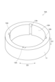
- FIG. 2 is a perspective view of the motor core according to the first embodiment.
- FIG. 3 is a plan view of the motor core according to the first embodiment.
- FIG. 4 is a perspective view of the back yoke shown in FIGS. 2 and 3.
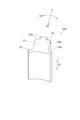
- FIG. 5 is a perspective view of the teeth piece shown in FIGS. 2 and 3.
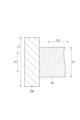
- FIG. 6 is a cross-sectional view of the teeth piece shown in FIGS. 2 and 3.
- FIG. 7 is a perspective view of a motor core according to the second embodiment.
- FIG. 8 is a plan view of a motor core according to the second embodiment.
- FIG. 9 is a perspective view of the back yoke shown in FIGS.
- FIG. 10 is a perspective view of the tooth piece shown in FIGS. 6 and 7.
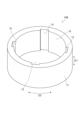
- FIG. FIG. 11 is a perspective view of a motor core according to the third embodiment.
- FIG. 12 is a perspective view of the back yoke shown in FIG.
- FIG. 13 is a cross-sectional view of the motor core shown in FIG.
- FIG. 14 is a perspective view of a motor core according to the fourth embodiment.
- FIG. 17 is a perspective view of a motor core according to the fifth embodiment.
- 18 is a perspective view of the tooth piece shown in FIG. 17.
- FIG. 17 is a perspective view of
- FIG. 19 is a cross-sectional view of the tooth piece shown in FIG. 17.
- FIG. 20 is a cross-sectional view of the tooth piece shown in FIG. 17.
- FIG. FIG. 21 is a perspective view of a motor core according to the sixth embodiment.
- FIG. 22 is a plan view of a motor core according to the sixth embodiment.
- FIG. 23 is a perspective view of the back yoke shown in FIGS. 21 and 22.
- FIG. FIG. 24 is a perspective view of the tooth piece shown in FIGS. 21 and 22.
- FIG. FIG. 25 is a cross-sectional view of the motor core shown in FIGS. 21 and 22.
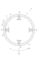
- Fig. 1 is a schematic cross-sectional view of a radial gap motor according to an embodiment.
- a radial gap motor 1 according to this embodiment includes a stator 2, a rotor 3 arranged rotatably relative to the stator 2, and a shaft 4 fixed to the rotor 3.
- the stator 2 and the rotor 3 are arranged to be spaced apart in the radial direction of the shaft 4.
- a shaft hole 5 through which the shaft 4 is inserted is formed in the center of the rotor 3.
- the stator 2 is a stator for a radial gap motor 1.
- the stator 2 includes a motor core 6 and a winding 7 wound around the motor core 6.
- the motor core 6 is the portion of the stator 2 excluding the winding 7, and is also called a stator core.
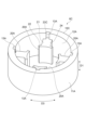
- Fig. 2 is a perspective view of the motor core according to the first embodiment.
- Fig. 3 is a plan view of the motor core according to the first embodiment.
- the motor core 6 according to this embodiment includes an annular back yoke 10 and a plurality of tooth pieces 20 that are formed separately from the back yoke 10 and joined to the back yoke 10.
- the motor core 6 is described as including four tooth pieces 20, but the number of tooth pieces 20 is not particularly limited as long as it is two or more.
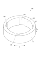
- FIG. 4 is a perspective view of the back yoke shown in FIGS. 2 and 3.
- the back yoke 10 is formed in a circular ring shape without being divided into multiple parts.
- the axial direction of the back yoke 10 is called the axial direction D1
- the radial direction of the back yoke 10 is called the radial direction D2
- the circumferential direction of the back yoke 10 is called the circumferential direction D3.
- the axial direction D1 is also the thickness direction of the back yoke 10 (the rotational axis direction of the rotor 3 in the radial gap motor 1).
- the radial direction D2 is also the radial direction of the ring formed by the back yoke 10 (the radial direction of the rotor 3 in the radial gap motor 1).
- the circumferential direction D3 is also the circumferential direction of the ring formed by the back yoke 10 (the rotational direction of the rotor 3 in the radial gap motor 1).
- the outer peripheral surface 11 of the back yoke 10 is formed in a perfect circle.
- a perfect circle includes not only a completely perfect circle shape, but also an approximately perfect circle shape that has been deformed due to manufacturing errors, etc.
- the inner peripheral surface 12 of the back yoke 10 may be formed in a perfect circle shape, or may be polygonal to make it easier to join multiple teeth pieces 20 to the back yoke 10.
- a plurality of recesses 13 are formed on the inner peripheral surface 12 of the back yoke 10.
- the recesses 13 are positioned at equal intervals in the circumferential direction D3.
- the number of recesses 13 is the same as the number of tooth pieces 20.
- Each of the recesses 13 extends from the inner peripheral surface 12 of the back yoke 10 toward the outside in the radial direction D2 and penetrates the back yoke 10 in the axial direction D1.
- the back yoke 10 is, for example, a powder compact formed by pressing soft magnetic powder coated with an insulating material.
- the powder compact back yoke 10 can be molded, for example, by a commercially available powder compacting device.
- the soft magnetic powder material is, for example, pure iron, iron silicon, or iron cobalt.
- the average particle size of the soft magnetic powder is, for example, 3 ⁇ m to 300 ⁇ m, 30 ⁇ m to 200 ⁇ m, or 50 ⁇ m to 150 ⁇ m.
- the insulating material is, for example, an insulating coating containing phosphoric acid, silicone, or the like.
- the average particle size of the soft magnetic powder is measured by a robot shifter (model number: RPS-205) manufactured by Seishin Enterprise Co., Ltd.
- the back yoke 10 may be a laminate in which multiple electromagnetic steel sheets are stacked.
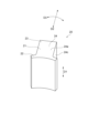
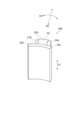
- FIG. 5 is a perspective view of the tooth piece shown in FIGS. 2 and 3.
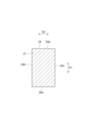
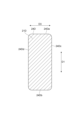
- FIG. 6 is a cross-sectional view of the tooth piece shown in FIGS. 2 and 3.
- the multiple tooth pieces 20 are joined to an annular back yoke 10 to form a motor core 6.
- Each of the multiple tooth pieces 20 is a portion around which the windings 7 are wound.
- Each of the multiple tooth pieces 20 is fitted into a respective one of multiple recesses 13 formed on the inner circumferential surface 12 of the back yoke 10.
- the multiple tooth pieces 20 are joined to the back yoke 10 so as to extend inward in the radial direction D2 from the back yoke 10.
- Each of the multiple tooth pieces 20 has a body 21 around which the winding 7 is wound, a flange 22 located at the end of the body 21 opposite the back yoke 10, and a base 23 located on the back yoke 10 side of the body 21 (opposite the flange 22).
- Each of the multiple tooth pieces 20 is joined to the back yoke 10 by fitting the base 23 into each of multiple recesses 13 formed on the inner surface 12 of the back yoke 10.
- the body 21 and base 23 extend linearly in the radial direction D2.
- the cross-sectional shape of the body 21 and base 23 in a direction perpendicular to the radial direction D2 is, for example, rectangular.
- the body 21 has a winding surface 24 around which the winding 7 is wound.
- the winding surface 24 is the surface of the body 21 around the radial direction D2, and is the surface of the body 21 that extends from the inner peripheral surface 12 of the back yoke 10 to the flange portion 22.
- the winding surface 24 has a first winding surface portion 24a and a second winding surface portion 24b that face the axial direction D1, and a third winding surface portion 24c and a fourth winding surface portion 24d that face the circumferential direction D3.
- the first winding surface portion 24a and the second winding surface portion 24b are adjacent to the third winding surface portion 24c on one side in the circumferential direction D3, and the first winding surface portion 24a and the second winding surface portion 24b are adjacent to the fourth winding surface portion 24d on the other side in the circumferential direction D3. Additionally, the third winding surface portion 24c and the fourth winding surface portion 24d are adjacent to the first winding surface portion 24a on one side in the axial direction D1, and the third winding surface portion 24c and the fourth winding surface portion 24d are adjacent to the second winding surface portion 24b on the other side in the axial direction D1.
- the flange 22 forms the inner circumferential surface of the stator 2 and the motor core 6.
- the length of the flange 22 in the circumferential direction D3 is longer than the length of the body 21 in the circumferential direction D3.
- the flange 22 extends beyond the body 21 to at least one side in the circumferential direction D3. In other words, when viewed from the radial direction D2, the flange 22 protrudes from the body 21 to at least one side in the circumferential direction D3. In this embodiment, the flange 22 extends beyond the body 21 to both sides in the circumferential direction D3. In other words, when viewed from the radial direction D2, the flange 22 protrudes from the body 21 to both sides in the circumferential direction D3.
- the multiple teeth pieces 20 are, for example, a powder compact formed by pressing soft magnetic powder coated with an insulating material.
- the multiple teeth pieces 20, which are powder compacts, can be molded, for example, by a commercially available powder compacting device.
- the soft magnetic powder material is, for example, pure iron, iron silicon, or iron cobalt.
- the average particle size of the soft magnetic powder is, for example, 3 ⁇ m to 300 ⁇ m, 30 ⁇ m to 200 ⁇ m, or 50 ⁇ m to 150 ⁇ m.
- the insulating material is, for example, an insulating coating containing phosphoric acid, silicone, or the like.
- the average particle size of the soft magnetic powder is measured using a robot shifter (model number: RPS-205) manufactured by Seishin Enterprise Co., Ltd.
- the multiple teeth pieces 20 may be a laminate in which multiple electromagnetic steel sheets are stacked.
- the manufacturing method for the motor core and stator includes a preparation process, a winding process, and a joining process.
- a circular back yoke 10 and a number of teeth pieces 20 that are separate from the back yoke 10 are prepared.
- the winding process can be performed at any timing before the joining process.
- the winding process can be performed before the preparation process, after the preparation process, or simultaneously with the preparation process.
- the winding 7 is wound around each of the multiple tooth pieces 20.
- Winding the winding 7 around each of the multiple tooth pieces 20 can be performed, for example, by spindle winding, nozzle winding, flyer winding, etc., in which the tooth pieces 20 are rotated to wind the winding 7 around the winding surface 24 of the tooth pieces 20.
- each of the multiple tooth pieces 20 is fitted into each of the multiple recesses 13 formed on the inner peripheral surface 12 of the back yoke 10. Then, the multiple tooth pieces 20 are joined to the back yoke 10 so that the multiple tooth pieces 20 extend inward in the radial direction D2 from the back yoke 10.
- the multiple tooth pieces 20 can be joined to the back yoke 10 by, for example, welding, adhesive bonding, etc.
- the multiple tooth pieces 20 are configured separately from the back yoke 10, so that the windings 7 can be wound around each of the multiple tooth pieces 20 before joining the multiple tooth pieces 20 to the back yoke 10. This allows the windings to be wound densely around each of the multiple tooth pieces 20, so that a high magnetic flux density can be obtained. Moreover, because the back yoke 10 is formed in an annular shape, there is no problem with a decrease in roundness that accompanies joining. This makes it possible to easily increase the roundness of the back yoke 10.
- the back yoke 10 and the multiple teeth pieces 20 are powder compacts, so it is difficult to cut them with high precision.
- the back yoke 10 is not divided, so there is no problem with reduced roundness that accompanies joining. Therefore, the roundness of the back yoke 10 can be easily improved.
- each of the multiple tooth pieces 20 is fitted into each of the multiple recesses 13 formed on the inner surface 12 of the back yoke 10, which increases the bonding strength between the back yoke 10 and the multiple tooth pieces 20 and also increases the positional accuracy of the multiple tooth pieces 20 relative to the back yoke 10.
- the tooth pieces 20 according to this embodiment are joined to the annular back yoke 10 to form the motor core 6 described above, so the windings 7 can be wound around them before joining them to the back yoke 10. This allows the windings 7 to be wound around the tooth pieces 20 at high density, resulting in a high magnetic flux density. Furthermore, the back yoke 10 to which the tooth pieces 20 are joined does not need to be divided, so there is no problem with reduced roundness that accompanies joining. This makes it easy to increase the roundness of the back yoke 10.
- the stator 2 includes the motor core 6 described above, which allows for a high magnetic flux density and makes it easy to improve the roundness of the back yoke 10.
- the radial gap motor 1 according to this embodiment is equipped with the stator 2 described above, which allows for a high magnetic flux density and makes it easy to improve the roundness of the back yoke 10.
- multiple tooth pieces 20 formed separately from the back yoke 10 are joined to the back yoke 10, so that the windings 7 can be wound around each of the multiple tooth pieces 20 before joining the multiple tooth pieces 20 to the back yoke 10.
- This allows the windings to be wound densely around each of the multiple tooth pieces 20, so a high magnetic flux density can be obtained.
- the back yoke 10 is formed in an annular shape, there is no problem with a decrease in roundness that accompanies joining. This makes it easy to increase the roundness of the back yoke 10.
- the windings 7 are wound around each of the multiple tooth pieces 20, which are formed separately from the back yoke 10, before joining the multiple tooth pieces 20 to the back yoke 10. This allows the windings 7 to be wound densely around each of the multiple tooth pieces 20, thereby obtaining a high magnetic flux density. Moreover, because the back yoke 10 is formed in an annular shape, there is no problem with a decrease in roundness that accompanies joining. This makes it easy to increase the roundness of the back yoke 10.
- the motor core according to the second embodiment is basically the same as the motor core according to the first embodiment (see FIGS. 2 to 6), but differs from the motor core according to the first embodiment in the joining structure between the back yoke and the multiple teeth pieces. Therefore, only the differences from the motor core according to the first embodiment will be described below, and descriptions of the same points as those in the motor core according to the first embodiment will be omitted.
- FIG. 7 is a perspective view of a motor core according to a second embodiment.
- FIG. 8 is a plan view of a motor core according to a second embodiment.
- a motor core 6A according to the second embodiment includes an annular back yoke 10A and a plurality of teeth pieces 20A that are formed separately from the back yoke 10A and joined to the back yoke 10A.
- FIG. 9 is a perspective view of the back yoke shown in FIG. 7 and FIG. 8.
- the back yoke 10A is formed in a circular ring shape without being divided into multiple parts.
- the inner peripheral surface 12A of the back yoke 10A has multiple recesses 13A formed thereon instead of the multiple recesses 13 of the first embodiment.
- Each of the multiple recesses 13A is shorter in the circumferential direction D3 than each of the multiple recesses 13 of the first embodiment.
- each of the multiple recesses 13A is narrower than each of the multiple recesses 13 of the first embodiment.
- each of the multiple recesses 13A is, for example, a dovetail groove.
- Each of the multiple recesses 13A being a dovetail groove means, for example, that each of the multiple recesses 13A is formed in a triangular shape that spreads outward in the radial direction D2 (toward the outer peripheral surface 11), has a portion whose width in the circumferential direction D3 spreads from the inner peripheral surface 12A toward the outer peripheral surface 11, has a surface that faces outward in the radial direction D2 (toward the outer peripheral surface 11) more than the circumferential direction D3, etc.
- FIG. 10 is a perspective view of the teeth piece shown in FIGS. 7 and 8. As shown in FIGS. 7 to 10, each of the multiple teeth pieces 20A is fitted into each of the multiple recesses 13A formed in the inner peripheral surface 12A of the back yoke 10A. The multiple teeth pieces 20A are joined to the back yoke 10A so as to extend inward in the radial direction D2 from the back yoke 10A.
- Each of the teeth pieces 20A has a body 21 around which the winding 7 is wound, a flange 22 located at the end of the body 21A opposite the back yoke 10A, and a protrusion 23A located on the back yoke 10 side of the body 21A (opposite the flange 22).
- Each of the teeth pieces 20A is joined to the back yoke 10A by fitting the protrusion 23A into each of the multiple recesses 13A formed on the inner peripheral surface 12A of the back yoke 10A.
- the protrusions 23A are dovetails corresponding to each of the multiple recesses.
- the protrusions 23A being dovetails means, for example, that the protrusions 23A are formed in a triangular shape that spreads outward in the radial direction D2 (toward the outer peripheral surface 11), that they have a portion whose width in the circumferential direction D3 spreads toward the protruding tip, and that they have a surface that faces outward in the radial direction D2 more than the circumferential direction D3.
- the projections 23A of the multiple teeth pieces 20A can be fitted into the multiple recesses 13A formed on the inner surface 12A of the back yoke 10A, for example, by inserting the projections 23A of the multiple teeth pieces 20A from one opening in the axial direction D1 of each of the multiple recesses 13A, and sliding each of the multiple teeth pieces 20A in the axial direction D1 relative to the back yoke 10A.
- the motor core 6A and the stator including the motor core 6A can be manufactured using a method similar to the manufacturing method of the motor core and the stator described above.
- the protrusions 23A of each of the multiple teeth pieces 20A are fitted into multiple recesses 13A formed on the inner circumferential surface 12A of the back yoke 10A, thereby increasing the bonding strength between the back yoke 10A and the multiple teeth pieces 20A, and also increasing the positional accuracy of the multiple teeth pieces 20A relative to the back yoke 10A.
- each of the multiple recesses 13A formed on the inner surface 12A of the back yoke 10A is a dovetail groove
- each of the protrusions 23A of the multiple tooth pieces 20A is a dovetail, which prevents the multiple tooth pieces 20A from coming loose from the back yoke 10A and increases the bonding strength between the back yoke 10A and the multiple tooth pieces 20A.
- the motor core according to the third embodiment is basically the same as the motor core according to the first embodiment (see FIGS. 2 to 6), but differs from the motor core according to the first embodiment in that the back yoke is longer in the axial direction than the teeth pieces. For this reason, only the differences from the motor core according to the first embodiment will be described below, and descriptions of the same points as those in the motor core according to the first embodiment will be omitted.
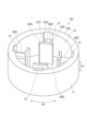
- FIG. 11 is a perspective view of a motor core according to a third embodiment.
- the motor core 6B according to the third embodiment includes an annular back yoke 10B and a plurality of teeth pieces 20 that are formed separately from the back yoke 10B and joined to the back yoke 10B.
- FIG. 12 is a perspective view of the back yoke shown in FIG. 11.
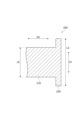
- FIG. 13 is a cross-sectional view of the motor core shown in FIG. 11.
- the back yoke 10B differs from the back yoke 10 of the first embodiment only in that it is longer in the axial direction D1 than the back yoke 10 of the first embodiment.
- the length L1 of the back yoke 10B in the axial direction D1 is longer than the length L2 of the teeth pieces 20 in the axial direction D1.
- the back yoke 10B extends to at least one side in the axial direction D1 beyond the teeth pieces 20.
- the back yoke 10B protrudes from the teeth pieces 20 to at least one side in the axial direction D1.
- the back yoke 10B extends to both sides in the axial direction D1 beyond the teeth pieces 20.
- the back yoke 10B protrudes from the teeth pieces 20 to both sides in the axial direction D1.
- the motor core 6B and the stator including the motor core 6B can be manufactured using a method similar to the manufacturing method of the motor core and the stator described above.
- the length L1 of the back yoke 10B in the axial direction D1 is longer than the length L2 of the multiple teeth pieces 20 in the axial direction D1, and the back yoke 10B extends to both sides in the axial direction D1 further than the multiple teeth pieces 20.
- a step is formed in which the back yoke 10B is higher than the multiple teeth pieces 20 in the axial direction D1, and this step increases the magnetic flux, thereby achieving a higher magnetic flux density.
- the motor core according to the fourth embodiment is basically the same as the motor core according to the second embodiment (see FIGS. 7 to 10), but differs from the motor core according to the second embodiment in that the back yoke is longer in the axial direction than the teeth pieces. For this reason, only the differences from the motor core according to the second embodiment will be described below, and descriptions of the same points as those in the motor core according to the second embodiment will be omitted.
- FIG. 14 is a perspective view of a motor core according to a fourth embodiment.
- the motor core 6C according to the fourth embodiment includes an annular back yoke 10C and a plurality of teeth pieces 20A that are formed separately from the back yoke 10C and joined to the back yoke 10C.
- FIG. 15 is a perspective view of the back yoke shown in FIG. 14.
- FIG. 16 is a cross-sectional view of the motor core shown in FIG. 14.
- the back yoke 10C differs from the back yoke 10A of the second embodiment only in that it is longer in the axial direction D1 than the back yoke 10A of the second embodiment.
- the length L3 of the back yoke 10C in the axial direction D1 is longer than the length L4 of the teeth pieces 20A in the axial direction D1.
- the back yoke 10C extends to at least one side in the axial direction D1 beyond the teeth pieces 20A.
- the back yoke 10B protrudes from the teeth pieces 20 to at least one side in the axial direction D1.
- the back yoke 10C extends to both sides in the axial direction D1 beyond the teeth pieces 20A.
- the back yoke 10B protrudes from the teeth pieces 20 to both sides in the axial direction D1.
- the motor core 6C and the stator including the motor core 6C can be manufactured using a method similar to the manufacturing method of the motor core and the stator described above.
- the length L3 of the back yoke 10C in the axial direction D1 is longer than the length L4 of the multiple teeth pieces 20A in the axial direction D1, and the back yoke 10C extends further on both sides in the axial direction D1 than the multiple teeth pieces 20A.
- a step is formed in which the back yoke 10C is higher than the multiple teeth pieces 20A in the axial direction D1, and this step increases the magnetic flux, resulting in a higher magnetic flux density.
- the motor core according to the fifth embodiment is basically the same as the motor core according to the third embodiment (see Figs. 11 to 13), but differs from the motor core according to the third embodiment in that the shapes of the body and flange of each of the multiple teeth pieces are different. Therefore, only the differences from the motor core according to the third embodiment will be described below, and descriptions of the same points as those of the motor core according to the third embodiment will be omitted.
- FIG. 17 is a perspective view of a motor core according to the fifth embodiment.
- the motor core 6D according to the fifth embodiment includes an annular back yoke 10B and a plurality of teeth pieces 20D that are formed separately from the back yoke 10B and joined to the back yoke 10B.
- FIG. 18 is a perspective view of the tooth piece shown in FIG. 17.
- FIGS. 19 and 20 are cross-sectional views of the tooth piece shown in FIG. 17.
- each of the multiple tooth pieces 20D has a body portion 21D that is joined to the back yoke 10B and around which the winding 7 is wound, a flange portion 22D located at the end of the body portion 21D opposite the back yoke 10B, and a base portion 23D located on the back yoke 10 side of the body portion 21.
- the base portion 23D has the same external shape as the body portion 21D.
- the body 21D has a winding surface 24D around which the winding 7 is wound.
- the winding surface 24D is the surface of the body 21D around the radial direction D2, and is the surface of the body 21D that extends from the inner peripheral surface 12 of the back yoke 10D to the flange 22D.
- the winding surface 24D has a first winding surface portion 24Da and a second winding surface portion 24Db that face the axial direction D1, and a third winding surface portion 24Dc and a fourth winding surface portion 24Dd that face the circumferential direction D3.
- the first winding surface portion 24Da and the second winding surface portion 24Db are adjacent to the third winding surface portion 24Dc on one side in the circumferential direction D3, and the first winding surface portion 24Da and the second winding surface portion 24Db are adjacent to the fourth winding surface portion 24Dd on the other side in the circumferential direction D3.
- the third winding surface portion 24Dc and the fourth winding surface portion 24Dd are adjacent to the first winding surface portion 24Da on one side in the axial direction D1
- the third winding surface portion 24Dc and the fourth winding surface portion 24Dd are adjacent to the second winding surface portion 24Db on the other side in the axial direction D1.
- first winding surface portion 24Da and the third winding surface portion 24Dc, the first winding surface portion 24Da and the fourth winding surface portion 24Dd, the second winding surface portion 24Db and the third winding surface portion 24Dc, and the second winding surface portion 24Db and the fourth winding surface portion 24Dd is connected in a curved shape.
- all of the first winding surface portion 24Da and the third winding surface portion 24Dc, the first winding surface portion 24Da and the fourth winding surface portion 24Dd, the second winding surface portion 24Db and the third winding surface portion 24Dc, and the second winding surface portion 24Db and the fourth winding surface portion 24Dd are connected in a curved shape.
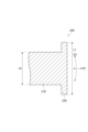
- the flange 22D differs from the flange 22 of the third embodiment only in that it is longer in the axial direction D1 than the flange 22 of the third embodiment.
- the length L5 of the flange 22D in the axial direction D1 is longer than the length L6 of the body 21D in the axial direction D1.
- the flange 22D extends to at least one side in the axial direction D1 beyond the body 21D. In other words, when viewed from the radial direction D2, the flange 22D protrudes from the body 21D to at least one side in the axial direction D1.
- the flange 22D extends to both sides in the axial direction D1 beyond the body 21D. In other words, when viewed from the radial direction D2, the flange 22D protrudes from the body 21D to both sides in the axial direction D1.
- the motor core 6D and the stator including the motor core 6D can be manufactured using a method similar to the manufacturing method of the motor core and the stator described above.
- At least one of the first winding surface portion 24Da and the third winding surface portion 24Dc, the first winding surface portion 24Da and the fourth winding surface portion 24Dd, the second winding surface portion 24Db and the third winding surface portion 24Dc, and the second winding surface portion 24Db and the fourth winding surface portion 24Dd are connected in a curved shape on the winding surface 24D of each of the multiple tooth pieces 20D, so that when the winding 7 is wound around the winding surface 24 of each of the multiple tooth pieces 20D, the winding 7 can be easily aligned along the winding surface 24D. This makes it possible to suppress the winding 7 from floating off the winding surface 24D, thereby increasing the magnetic flux density.
- the length L5 of the flange 22D in the axial direction D1 is longer than the length L6 of the body 21D in the axial direction D1, and the flange 22D extends further to at least one side in the axial direction D1 than the body 21D.
- a step is formed in which the flange 22D is higher than the body 21D in the axial direction D1, and this step increases the magnetic flux, resulting in a higher magnetic flux density.
- At least one of the first winding surface portion 24Da and the third winding surface portion 24Dc, the first winding surface portion 24Da and the fourth winding surface portion 24Dd, the second winding surface portion 24Db and the third winding surface portion 24Dc, and the second winding surface portion 24Db and the fourth winding surface portion 24Dd is connected in a curved shape on the winding surface 24D of the tooth piece 20D, so that when the winding 7 is wound around the winding surface 24D of the tooth piece 20D, the winding 7 can be easily aligned with the winding surface 24D. This makes it possible to suppress the floating of the winding 7 from the winding surface 24D, thereby increasing the magnetic flux density.
- the motor core according to the sixth embodiment is basically the same as the motor core according to the first embodiment (see FIGS. 2 to 6), but the shape of the multiple recesses in the back yoke and the shape of the body of each of the multiple teeth pieces are different from those of the motor core according to the first embodiment. Therefore, only the differences from the motor core according to the first embodiment will be described below, and descriptions of the same points as those of the motor core according to the first embodiment will be omitted.
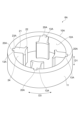
- FIG. 21 is a perspective view of a motor core according to a sixth embodiment.
- FIG. 22 is a plan view of the motor core according to the sixth embodiment.
- the motor core 6E according to the sixth embodiment includes a circular back yoke 10E and a plurality of teeth pieces 20E that are formed separately from the back yoke 10E and joined to the back yoke 10E.
- FIG. 23 is a perspective view of the back yoke shown in FIGS. 21 and 22.
- the back yoke 10E is formed in a circular ring shape without being divided into multiple parts.
- a plurality of recesses 13E are formed on the inner peripheral surface 12E of the back yoke 10E instead of the multiple recesses 13 of the first embodiment.
- Each of the multiple recesses 13E is longer in the circumferential direction D3 than each of the multiple recesses 13 of the first embodiment. In other words, each of the multiple recesses 13E is wider than each of the multiple recesses 13 of the first embodiment.
- Figure 24 is a perspective view of the teeth piece shown in Figures 21 and 22.
- Figure 25 is a cross-sectional view of the motor core shown in Figures 21 and 22.
- each of the multiple teeth pieces 20E is fitted into each of the multiple recesses 13E formed in the inner surface 12E of the back yoke 10E.
- the multiple teeth pieces 20E are joined to the back yoke 10E so as to extend inward in the radial direction D2 from the back yoke 10E.
- Each of the multiple tooth pieces 20E has a body 21 around which the winding 7 is wound, a flange 22 located at the end of the body 21A opposite the back yoke 10, and a base 23E located on the back yoke 10E side of the body 21 (opposite the flange 22).
- Each of the multiple tooth pieces 20E is joined to the back yoke 10E by fitting the base 23E into each of multiple recesses 13E formed on the inner circumferential surface 12E of the back yoke 10E.
- the base 23E is longer in the circumferential direction D3 than the base 23 of the first embodiment. That is, the base 23E is also wider than the base 23 of the first embodiment.
- the length L7 of the base 23E in the circumferential direction D3 is longer than the length L8 of the body 21 in the circumferential direction D3.
- the base 23E extends to at least one side in the circumferential direction D3 beyond the body 21. That is, when viewed from the radial direction D2, the base 23E protrudes from the body 21 to at least one side in the circumferential direction D3.
- the base 23E extends to both sides in the circumferential direction D3 beyond the body 21. That is, when viewed from the radial direction D2, the base 23E protrudes from the body 21 to both sides in the circumferential direction D3.
- the motor core 6E and a stator including the motor core 6E can be manufactured using a method similar to the manufacturing method of the motor core and stator described above.
- the length L7 of the base 23E in the circumferential direction D3 is longer than the length L8 of the body 21 in the circumferential direction D3, and the base 23E extends beyond the body 21 to at least one side in the circumferential direction D3. This allows the multiple teeth pieces 20E to be stably joined to the back yoke 10E, and also prevents the multiple teeth pieces 20E from collapsing relative to the back yoke 10E.
- This disclosure can be used as a motor core, a stator, a teeth piece, a radial gap motor, a method for manufacturing a motor core, and a method for manufacturing a stator.
Landscapes
- Engineering & Computer Science (AREA)
- Power Engineering (AREA)
- Iron Core Of Rotating Electric Machines (AREA)
Abstract
Un noyau de moteur selon la présente invention est destiné à un moteur à entrefer radial et comprend une culasse arrière annulaire et une pluralité de pièces de dents qui sont formées séparément de la culasse arrière. La pluralité de pièces de dents sont reliées à la culasse arrière de manière à s'étendre de la culasse arrière vers l'intérieur dans la direction radiale de la culasse arrière. Un procédé de fabrication du noyau de moteur comprend une étape consistant à préparer une culasse annulaire et une pluralité de pièces de dents formées séparément de la culasse et une étape consistant à assembler la pluralité de pièces de dents à la culasse de sorte que la pluralité de pièces de dents s'étendent de la culasse vers l'intérieur dans la direction radiale de la culasse.
Priority Applications (2)
| Application Number | Priority Date | Filing Date | Title |
|---|---|---|---|
| PCT/JP2023/029996 WO2025041223A1 (fr) | 2023-08-21 | 2023-08-21 | Noyau de moteur, stator, pièce de dent, moteur à entrefer radial, procédé de fabrication de noyau de moteur et procédé de fabrication de stator |
| JP2025541182A JPWO2025041223A1 (fr) | 2023-08-21 | 2023-08-21 |
Applications Claiming Priority (1)
| Application Number | Priority Date | Filing Date | Title |
|---|---|---|---|
| PCT/JP2023/029996 WO2025041223A1 (fr) | 2023-08-21 | 2023-08-21 | Noyau de moteur, stator, pièce de dent, moteur à entrefer radial, procédé de fabrication de noyau de moteur et procédé de fabrication de stator |
Publications (1)
| Publication Number | Publication Date |
|---|---|
| WO2025041223A1 true WO2025041223A1 (fr) | 2025-02-27 |
Family
ID=94731811
Family Applications (1)
| Application Number | Title | Priority Date | Filing Date |
|---|---|---|---|
| PCT/JP2023/029996 Pending WO2025041223A1 (fr) | 2023-08-21 | 2023-08-21 | Noyau de moteur, stator, pièce de dent, moteur à entrefer radial, procédé de fabrication de noyau de moteur et procédé de fabrication de stator |
Country Status (2)
| Country | Link |
|---|---|
| JP (1) | JPWO2025041223A1 (fr) |
| WO (1) | WO2025041223A1 (fr) |
Citations (6)
| Publication number | Priority date | Publication date | Assignee | Title |
|---|---|---|---|---|
| JPH09215230A (ja) * | 1996-02-09 | 1997-08-15 | Toshiba Corp | 電動機 |
| JPH10234145A (ja) * | 1997-02-19 | 1998-09-02 | Toshiba Corp | インナーロータ形モータのステータ |
| JP2005261183A (ja) * | 2004-03-09 | 2005-09-22 | Lg Electronics Inc | 無整流子直流電動機の固定子製造方法及びその方法により製造された無整流子直流電動機の固定子 |
| JP2006087244A (ja) * | 2004-09-16 | 2006-03-30 | Asmo Co Ltd | 回転電機 |
| JP2006246621A (ja) * | 2005-03-03 | 2006-09-14 | Asmo Co Ltd | 回転電機のコア、その製造方法、及び埋込磁石型モータ |
| JP2008022646A (ja) * | 2006-07-13 | 2008-01-31 | Yaskawa Electric Corp | 永久磁石型モータ用固定子、永久磁石型モータ、およびその固定子の製造方法 |
-
2023
- 2023-08-21 WO PCT/JP2023/029996 patent/WO2025041223A1/fr active Pending
- 2023-08-21 JP JP2025541182A patent/JPWO2025041223A1/ja active Pending
Patent Citations (6)
| Publication number | Priority date | Publication date | Assignee | Title |
|---|---|---|---|---|
| JPH09215230A (ja) * | 1996-02-09 | 1997-08-15 | Toshiba Corp | 電動機 |
| JPH10234145A (ja) * | 1997-02-19 | 1998-09-02 | Toshiba Corp | インナーロータ形モータのステータ |
| JP2005261183A (ja) * | 2004-03-09 | 2005-09-22 | Lg Electronics Inc | 無整流子直流電動機の固定子製造方法及びその方法により製造された無整流子直流電動機の固定子 |
| JP2006087244A (ja) * | 2004-09-16 | 2006-03-30 | Asmo Co Ltd | 回転電機 |
| JP2006246621A (ja) * | 2005-03-03 | 2006-09-14 | Asmo Co Ltd | 回転電機のコア、その製造方法、及び埋込磁石型モータ |
| JP2008022646A (ja) * | 2006-07-13 | 2008-01-31 | Yaskawa Electric Corp | 永久磁石型モータ用固定子、永久磁石型モータ、およびその固定子の製造方法 |
Also Published As
| Publication number | Publication date |
|---|---|
| JPWO2025041223A1 (fr) | 2025-02-27 |
Similar Documents
| Publication | Publication Date | Title |
|---|---|---|
| WO2007141907A1 (fr) | noyau de fer de type fendu et son procédé de fabrication, et noyau de fer de stator | |
| JP3432474B2 (ja) | 回転電機の固定子 | |
| CN113300501B (zh) | 定子铁芯、电机、压缩机和车辆 | |
| JPH077875A (ja) | 回転電機の固定子 | |
| JP2016036223A (ja) | 回転電機の固定子 | |
| JP2012125054A (ja) | 回転電機 | |
| JP5258801B2 (ja) | モータの電機子 | |
| JPH08149725A (ja) | 回転電機の固定子 | |
| JP2014187856A (ja) | ステータコアの絶縁構造及びステータの組付方法 | |
| JP2012050178A (ja) | ステータコア、ステータ及びステータコアの組付方法 | |
| JP2012023805A (ja) | 電動機の固定子とその製造方法 | |
| WO2025041223A1 (fr) | Noyau de moteur, stator, pièce de dent, moteur à entrefer radial, procédé de fabrication de noyau de moteur et procédé de fabrication de stator | |
| WO2024052989A1 (fr) | Noyau de stator | |
| TWI819151B (zh) | 電樞模具構造 | |
| JP4295691B2 (ja) | 回転電機の電機子 | |
| JPH0328143B2 (fr) | ||
| JP2008061319A (ja) | ステータおよびステータの製造方法および内径リング | |
| WO2020059517A1 (fr) | Noyau de stator, dispositif électrique rotatif et procédé de fabrication de noyau de stator | |
| JP5907833B2 (ja) | 回転電機の固定子 | |
| JP5292134B2 (ja) | ステータおよびモータ | |
| WO2025052586A1 (fr) | Procédé de fabrication de noyau de moteur et procédé de fabrication de stator | |
| JP7339918B2 (ja) | アキシャルギャップ型回転電機用の電機子コア、アキシャルギャップ型回転電機用の電機子コアの製造方法 | |
| JP7569600B2 (ja) | ステータ及びモータ | |
| JP2021136726A (ja) | ステータ、ステータの製造方法、モータ | |
| JP5130242B2 (ja) | ステータ |
Legal Events
| Date | Code | Title | Description |
|---|---|---|---|
| 121 | Ep: the epo has been informed by wipo that ep was designated in this application |
Ref document number: 23949684 Country of ref document: EP Kind code of ref document: A1 |
|
| ENP | Entry into the national phase |
Ref document number: 2025541182 Country of ref document: JP Kind code of ref document: A |
|
| WWE | Wipo information: entry into national phase |
Ref document number: 2025541182 Country of ref document: JP |
|
| NENP | Non-entry into the national phase |
Ref country code: DE |