WO2025032654A1 - コイル装置および車載機器 - Google Patents
コイル装置および車載機器 Download PDFInfo
- Publication number
- WO2025032654A1 WO2025032654A1 PCT/JP2023/028624 JP2023028624W WO2025032654A1 WO 2025032654 A1 WO2025032654 A1 WO 2025032654A1 JP 2023028624 W JP2023028624 W JP 2023028624W WO 2025032654 A1 WO2025032654 A1 WO 2025032654A1
- Authority
- WO
- WIPO (PCT)
- Prior art keywords
- duct
- casing
- wall surface
- coil device
- coil
- Prior art date
- Legal status (The legal status is an assumption and is not a legal conclusion. Google has not performed a legal analysis and makes no representation as to the accuracy of the status listed.)
- Pending
Links
Images




Classifications
-
- H—ELECTRICITY
- H01—ELECTRIC ELEMENTS
- H01F—MAGNETS; INDUCTANCES; TRANSFORMERS; SELECTION OF MATERIALS FOR THEIR MAGNETIC PROPERTIES
- H01F37/00—Fixed inductances not covered by group H01F17/00
-
- H—ELECTRICITY
- H05—ELECTRIC TECHNIQUES NOT OTHERWISE PROVIDED FOR
- H05K—PRINTED CIRCUITS; CASINGS OR CONSTRUCTIONAL DETAILS OF ELECTRIC APPARATUS; MANUFACTURE OF ASSEMBLAGES OF ELECTRICAL COMPONENTS
- H05K7/00—Constructional details common to different types of electric apparatus
- H05K7/20—Modifications to facilitate cooling, ventilating, or heating
Definitions
- This disclosure relates to a coil device and an in-vehicle device equipped with a coil device.
- Some on-board equipment includes a coil device such as a reactor or transformer. To prevent damage to the coil device due to heat generation when current is applied, the on-board equipment has a structure that dissipates heat generated by the coil device.
- An example of this type of on-board equipment is disclosed in Patent Document 1.
- the choke coil of the inverter circuit included in the electric motor disclosed in Patent Document 1 is installed at the bottom of a structural member suspended from the motor housing. The heat generated by the choke coil is dissipated to the outside of the electric motor via the structural member and the motor housing.
- This disclosure has been made in consideration of the above-mentioned circumstances, and aims to provide a coil device that enables the miniaturization of the in-vehicle equipment to be mounted therein, and a small in-vehicle equipment.
- the coil device of the present disclosure includes a coil and a casing.
- the coil is wound around a central axis.
- the casing is a casting or injection molded product having an internal cavity, and houses the coil in the cavity.
- the casing is housed in a duct that extends in a direction intersecting the vertical direction inside the housing of the vehicle-mounted device and forms a space into which air outside the housing flows, with at least a portion of the bottom surface of the casing abutting a first wall surface that is the inner surface of the duct on the lower vertical side.
- the casing is fixed to the first wall surface and to a second wall surface that is the inner surface of the duct on the upper vertical side.
- the casing which is a cast or injection molded product that houses the coil, is fixed to the first wall surface, with at least a portion of the bottom surface of the casing abutting against the first wall surface, which is the inner surface of the vertical lower side of the duct.
- the casing is also fixed to the second wall surface, which is the inner surface of the vertical upper side of the duct. Therefore, no member for supporting the coil is required, such as a structural member that is suspended from the housing and supports the coil. This makes it possible to miniaturize on-board equipment equipped with a coil device.
- FIG. 1 is a perspective view of an in-vehicle device according to a first embodiment
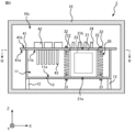
- 2 is a cross-sectional view taken along line II-II in FIG. 1 of the in-vehicle device according to the first embodiment
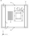
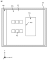
- 3 is a cross-sectional view taken along line III-III in FIG. 2 of the in-vehicle device according to the first embodiment
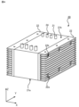
- FIG. 1 is a perspective view of a coil device according to a first embodiment
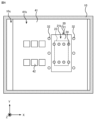
- 1 is a cross-sectional view of an in-vehicle device according to a second embodiment
- 6 is a cross-sectional view taken along line VI-VI in FIG. 5 of the in-vehicle device according to the second embodiment.
- FIG. 13 is a perspective view of a modified example of the coil device according to the embodiment; 1 is a cross-sectional view of a modified example of an in-vehicle device according to an embodiment;
- the on-board device 1 will be described by taking an on-board device mounted on a railway vehicle as an example.
- the on-board device 1 shown in Fig. 1, Fig. 2 which is a cross-sectional view taken along line II-II in Fig. 1, and Fig. 3 which is a cross-sectional view taken along line III-III in Fig. 2, is attached to a railway vehicle and includes a housing 10 having a duct 11 therein.
- the on-board device 1 includes a coil device 20 housed in the duct 11, a first fastening member 31 and a second fastening member 32 which fix the coil device 20 to the duct 11, and a heat receiving block 41 which forms a part of the duct 11.
- the heat receiving block 41 has a first main surface 41a facing the inside of the duct 11, and a second main surface 41b located on the opposite side of the first main surface 41a.
- the vehicle-mounted device 1 includes an electronic component 42 attached to the second main surface 41b, and a heat dissipation member 43 housed in the duct 11.
- the Z axis indicates the vertical direction when the railway vehicle is positioned horizontally.
- the X axis indicates the direction of travel of the railway vehicle, and the Y axis indicates the width direction of the railway vehicle.
- the X axis, Y axis, and Z axis are perpendicular to each other.
- the on-board device 1 is, for example, a power conversion device that converts power supplied from an overhead line into three-phase AC power for supplying to an electric motor that generates the propulsive force of a railway vehicle, and supplies the three-phase AC power to the main motor.
- the coil device 20 provided in the on-board device 1, which is a power conversion device, is, for example, a reactor that generates heat when current is applied, and is housed in the duct 11. The heat generated by the coil device 20 is dissipated into the air flowing into the duct 11 from outside the housing 10, thereby cooling the coil device 20.
- the casing 21 of the coil device 20 is fixed to the duct 11, there is no need to provide any additional members to support the coil device 20, and the on-board device 1 can be made smaller.
- the housing 10 is attached to the underfloor of a railway vehicle by a mounting member (not shown). Ventilation holes 10a, 10b communicating with the duct 11 are formed on two surfaces of the housing 10 that face each other in the Y-axis direction. The ventilation holes 10a, 10b are formed at positions facing each other in the Y-axis direction.
- the duct 11 extends inside the housing 10 in a direction intersecting the vertical direction to form a space into which air from outside the housing 10 flows.
- the duct 11 extends horizontally when the railway vehicle on which the on-board device 1 is mounted is positioned horizontally.
- the duct 11 houses the coil device 20 and the heat dissipation member 43.
- the duct 11 is supported by a support member 12 attached to the inner surface of the housing 10.
- the duct 11 is formed by a lower duct portion 13 having a portion perpendicular to the Z axis and a portion perpendicular to the Y axis, and a part of the heat receiving block 41.
- the duct lower part 13 of the duct 11 vertically supports the coil device 20 housed in the duct 11.
- the duct 11 has a strength sufficient to prevent deformation due to vibrations caused when the railway vehicle is traveling.
- the duct lower part 13 is preferably a cast or injection molded part made of a material capable of providing sufficient strength, such as a metal material such as aluminum, iron, or stainless steel.
- the duct lower part 13 may be a cast or injection molded part with a thickness of at least 10 millimeters at any point.
- the in-vehicle device 1 is required to have a degree of sealing that can prevent air from outside the housing 10 from flowing into the space 10c surrounded by the outer surface of the duct 11 in which the electronic components 42 are housed and the inner surface of the housing 10. For this reason, it is preferable that the end faces in the Y-axis direction of the duct lower part 13 and the heat receiving block 41 are smooth flat surfaces that abut against the housing 10. It is preferable that the end faces on the positive side of the Y-axis of the duct lower part 13 and the heat receiving block 41 are smoothly connected to each other, and that the end faces on the negative side of the Y-axis of the duct lower part 13 and the heat receiving block 41 are smoothly connected to each other. Being smoothly connected means that the slope of the tangent plane is continuous.
- the end faces of the duct lower part 13 and the heat receiving block 41 on the positive side of the Y axis are located on the same plane, and the end faces of the duct lower part 13 and the heat receiving block 41 on the negative side of the Y axis are located on the same plane.
- the in-vehicle device 1 be provided with an airtight material, such as a waterproof and dustproof resin, that is filled between the end faces of the duct lower portion 13 and the heat receiving block 41 in the Y-axis direction and the housing 10.
- an airtight material such as a waterproof and dustproof resin
- the coil device 20 shown in Figures 1 to 4 comprises a casing 21 which is a cast or injection molded product having an internal cavity, a number of fins 22 attached to the side of the casing 21 and housed in the duct 11, a coil 23 housed in the cavity of the casing 21, and a conductor 24 whose one end is connected to the coil 23 and which is pulled to the outside of the casing 21.
- the casing 21 has a box that opens at the top in the vertical direction, and a lid that can open and close the opening at the top in the vertical direction of the box.
- the casing 21 is a cast or injection molded product, and therefore has smaller size tolerances than processed products formed by bending metal. For this reason, as shown in FIG. 2, the bottom surface 21a of the casing 21 can abut against the first wall surface 11a, which is the inner surface of the lower vertical side of the duct 11, and the top surface 21b of the casing 21 can abut against the second wall surface 11b, which is the inner surface of the upper vertical side of the duct 11.
- the coil device 20 including the casing 21 is fixed to the duct 11 and supported by the duct 11.
- the coil device 20 functions as a structural member that maintains the internal space of the duct 11 by abutting the casing 21 against the first wall surface 11a and the second wall surface 11b of the duct 11. For this reason, it is preferable that the casing 21 has a strength sufficient to prevent deformation due to vibrations caused when the railway vehicle is traveling.
- the casing 21 may be formed, for example, from an aluminum plate having a thickness of at least 10 millimeters.
- the fins 22 are provided on the side of the casing 21, specifically, on the surface of the casing 21 that intersects with the X-axis.
- the fins 22 are preferably flat plate-like members.
- the main surface of the fins 22 extends in the extension direction of the duct 11.
- the fins 22 are attached to the casing 21 with the main surface of the fins 22 oriented parallel to the XY plane.
- the fins 22 extend in the extension direction of the duct 11, i.e., in the direction in which air flows inside the duct 11. Therefore, heat generated in the coil 23 is efficiently transferred from the fins 22 to the air inside the duct 11. As a result, the coil 23 is cooled.
- the fins 22 are preferably made of a material with high thermal conductivity, for example, a metal such as copper or aluminum.
- the fins 22 are fixed to the side of the casing 21 by any attachment method, such as fitting, brazing, welding, bonding with an adhesive, or fastening with a fastening member.
- the fins 22 need only be fixed to the casing 21 with enough strength that the positional relationship between the fins 22 and the casing 21 does not change when subjected to vibrations while the railway vehicle is running.
- the fin 22 located at the lower end in the vertical direction is fixed to the first wall surface 11a by the first fastening member 31 with the fin 22 abutting the first wall surface 11a with its surface.
- the fin 22 located at the upper end in the vertical direction is fixed to the second wall surface 11b by the second fastening member 32 with the fin 22 abutting the second wall surface 11b with its surface.
- the fin 22 located at the lower end in the vertical direction and the fin 22 located at the upper end in the vertical direction abut the first wall surface 11a and the second wall surface 11b, respectively, so that heat generated in the coil 23 is efficiently transferred from the fin 22 to the duct 11.
- the coil 23 is housed in the casing 21 in any orientation. It is preferable that the coil 23 is housed in the casing 21 with its central axis oriented parallel to the Z-axis or Y-axis.
- the coil 23 is housed in a box that the casing 21 has, and the casing 21 is housed in the duct 11 with the opening of the box closed by a lid that the casing 21 has, so that the coil 23 is prevented from coming into contact with the air outside the housing 10 that contains dust, moisture, etc.
- One end of the conductor 24 is disposed inside the casing 21 and connected to the coil 23.
- the conductor 24 is routed through a through hole formed in the lid of the casing 21 and the heat receiving block 41, inside the housing 10, and to the outside of the duct 11.
- the other end of the conductor 24 is connected to an electronic device inside the housing 10 (not shown).
- the first fastening member 31 has a bolt that passes through the duct lower portion 13 and the fin 22 at the lower end in the vertical direction, and a nut that tightens the bolt.
- the bolt passes through the fin 22 at the lower end in the vertical direction and is positioned in the gap 22a between the fins 22 shown in Figure 4.
- the second fastening member 32 has a bolt that passes through the heat receiving block 41 that forms the duct 11 and the fin 22 at the vertical upper end, and a nut that tightens the bolt.
- the bolt passes through the fin 22 at the vertical upper end and is positioned in the gap 22b between the fins 22 shown in Figure 4.
- the heat receiving block 41 has a first main surface 41a and a second main surface 41b located opposite the first main surface 41a.
- the heat receiving block 41 is preferably a flat plate-like member. In the first embodiment, the first main surface 41a and the second main surface 41b face each other in the Z-axis direction.
- the heat receiving block 41 forms the duct 11. In detail, a part of the first main surface 41a of the heat receiving block 41 corresponds to the second wall surface 11b of the duct 11.
- a plurality of heat dissipation members 43 are attached to the first main surface 41a facing the inside of the duct 11.
- An electronic component 42 which is a heat generating body, is attached to the second main surface 41b located opposite the first main surface 41a of the heat receiving block 41.
- the heat receiving block 41 is attached to the vertical upper end of the duct lower part 13, and together with the duct lower part 13 forms the duct 11.
- the heat receiving block 41 may be attached to the duct lower part 13 by any attachment method, such as fitting, brazing, welding, bonding with an adhesive, fastening with a fastening member, etc., as long as it is strong enough that the positional relationship between the heat receiving block 41 and the duct lower part 13 does not change when subjected to vibrations while the railway vehicle is running.
- the heat receiving block 41 forms part of the duct 11, it is preferable that, like the duct 11, it has a strength sufficient to prevent deformation due to vibrations caused when the railway vehicle is traveling. In addition, it is preferable that the heat receiving block 41 has a thermal conductivity sufficient to transfer heat generated by the electronic components 42 to the heat dissipation member 43.
- the heat receiving block 41 is preferably made of a material that has sufficient strength and high thermal conductivity, such as aluminum. Specifically, the heat receiving block 41 may be made of an aluminum plate having a thickness of at least 10 millimeters.
- the electronic component 42 is, for example, a switching element included in the power conversion circuit, and generates heat when current is applied.
- the electronic component 42 is attached to the second main surface 41b located opposite the first main surface 41a that forms the second wall surface 11b of the duct 11, so that the air outside the housing 10 that flows into the inside of the duct 11 is prevented from coming into contact with the electronic component 42.
- the heat dissipation members 43 are attached to the first main surface 41a of the heat receiving block 41.
- the heat dissipation members 43 are arranged in the X-axis direction, and adjacent heat dissipation members 43 are positioned with a gap between them.
- the heat dissipation members 43 dissipate heat transferred from the electronic component 42 through the heat receiving block 41 to the air passing through the gap.
- the heat dissipation members 43 have a fin shape.
- the main surface of the heat dissipation member 43 extends in the extension direction of the duct 11.
- the heat dissipation member 43 is attached to the heat receiving block 41 with the main surface oriented parallel to the YZ plane.
- the heat dissipation member 43 extends in the extension direction of the duct 11, i.e., in the direction in which the air flows inside the duct 11, so that the heat generated in the electronic component 42 is efficiently transferred from the heat dissipation member 43 to the air inside the duct 11. As a result, the electronic component 42 is cooled.
- the heat dissipation member 43 is preferably formed from a material with high thermal conductivity, for example, a metal such as copper or aluminum.
- the heat dissipation member 43 is fixed to the first main surface 41a of the heat receiving block 41 by any attachment method, such as fitting, brazing, welding, bonding with an adhesive, or fastening with a fastening member.
- the heat dissipation member 43 needs to be fixed to the heat receiving block 41 with enough strength that the positional relationship between the heat dissipation member 43 and the heat receiving block 41 does not change when subjected to vibrations while the railway vehicle is running.
- Each heat dissipation member 43 transfers heat transferred from the electronic component 42 via the heat receiving block 41 to the air flowing into the inside of the duct 11. As a result, the electronic component 42 is cooled.
- the heat dissipation member 43 has a fin shape, and the main surface of the heat dissipation member 43 extends in the extension direction of the duct 11.
- the heat dissipation member 43 is attached to the heat receiving block 41 with the main surface of the heat dissipation member 43 oriented parallel to the YZ plane.
- air that flows into the duct 11 from the ventilation hole 10a passes between the fins 22 or between the heat dissipation members 43, and flows out of the housing 10 from the ventilation hole 10b.
- the heat generated in the coil 23 is transferred to the air passing between the fins 22, thereby cooling the coil 23.
- the heat generated in the electronic component 42 is transferred to the air passing between the heat dissipation members 43, thereby cooling the electronic component 42.
- the coil device 20 includes a casing 21 that is a cast or injection molded product with a small tolerance, so there is no need to provide clearance around the casing 21 within the duct 11, and the casing 21 can be housed in the duct 11 in a state where it is in contact with the first wall surface 11a and the second wall surface 11b of the duct 11.
- the duct 11 supports the coil device 20 having the casing 21 abutting against the first wall surface 11a, so there is no need to provide any additional members to support the coil device 20. Therefore, the size of the in-vehicle device 1 is smaller than that of an in-vehicle device that has a member supporting the coil device.
- the casing 21 abuts against the first wall surface 11a and the second wall surface 11b of the duct 11, which prevents the coil 23 housed in the casing 21 from vibrating together with the casing 21 due to vibrations caused when the railway vehicle is traveling.
- the casing 21 abuts against the first wall surface 11a and the second wall surface 11b of the duct 11, thereby serving as a structural member that maintains the internal space of the duct 11. Therefore, there is no need to provide additional strength members to maintain the internal space of the duct 11, and the size of the duct 11 in the in-vehicle device 1 is smaller than that of a power conversion device that includes strength members that maintain the internal space of the duct.
- the fins 22 located at the lower end in the vertical direction and the fins 22 located at the upper end in the vertical direction abut the first wall surface 11a and the second wall surface 11b, respectively, so that heat generated in the coil 23 is efficiently transferred from the fins 22 to the duct 11. As a result, the cooling performance of the coil device 20 in the in-vehicle device 1 is improved.
- the method of arranging the coil device 20 is not limited to the above example.
- a power conversion device in which the coil device 20 is arranged in a manner different from that in the first embodiment will be described in the second embodiment, focusing on the difference from the first embodiment.
- the configuration of the vehicle-mounted device 2 according to the second embodiment shown in FIG. 5 is the same as that of the vehicle-mounted device 1 according to the first embodiment.
- a portion of the coil device 20 protrudes into the space 10c outside the duct 11.
- a communication hole 41c is formed in the heat receiving block 41.
- the casing 21, which protrudes into the space 10c through the communication hole 41c, is preferably fixed to the duct 11 in a state of abutment against a hole wall surface 41d, which is the wall surface of the communication hole 41c.
- the hole wall surface 41d is coated with, for example, a resin that is waterproof and dustproof.
- the coil device 20 provided in the in-vehicle device 2 according to the second embodiment is fixed to the duct 11 with a portion of it protruding outside the duct 11. This makes it possible to determine the size of the coil device 20 independently of the size of the duct 11, increasing the degree of freedom in designing the coil device 20.
- the present disclosure is not limited to the above-described embodiment.
- "fixed” includes “integrally formed.”
- the casing 21 and the fins 22 may be integrally formed. By integrally forming the casing 21 and the fins 22, heat is efficiently transferred from the coil 23 housed in the casing 21 to the fins 22 via the casing 21.
- the number of coil devices that an on-board device may have is arbitrary.
- the on-board device 3 shown in FIG. 9 has two coil devices 20 housed in the same duct 11, and heat dissipation members 43, 44.
- the configuration of each coil device 20 is similar to the coil device 20 that is provided in the on-board device 1 shown in embodiment 1.
- the vertical length of the heat dissipation member 44 is longer than the vertical length of the heat dissipation member 43.
- the on-board device 3 may have multiple coil devices 20, parts of which protrude outside the duct 11, as shown in embodiment 2.
- each heat dissipation member 43, 44 may be a protrusion extending in a direction away from the first main surface 41a that forms the second wall surface 11b. In this case, it is preferable that the tip of each heat dissipation member 43, 44 is thinner than the portion fixed to the first main surface 41a.
- the heat dissipation members 43, 44 may be heat pipes.
- the heat dissipation members 43, 44 have a main pipe embedded in the heat receiving block 41 and extending along the air flow in the duct 11, and a branch pipe connected to the main pipe and extending in a direction away from the heat receiving block 41. Furthermore, fins fixed to the branch pipe may be provided.
- the waterproof and dustproof treatment is, for example, the application of a resin that has waterproof and dustproof properties.
- the on-board devices 1, 2, and 3 are not limited to power conversion devices that convert power supplied from overhead lines into three-phase AC power for supplying to the main motor, but may be any device that has a heating element and is mounted on a vehicle.
- the on-board devices 1, 2, and 3 are not limited to railroad cars, but may be mounted on any moving object such as an automobile, aircraft, or ship.
- the enclosure 10 may be mounted on the roof of a rail car.
- the orientation in which the housing 10 is attached to the railcar is not limited to the above example.
- the on-vehicle device 1-3 may be mounted on the railcar with the extension direction of the duct 11 perpendicular to the X-axis direction.
- the structure of the duct 11 is not limited to the above example, and may be any structure that allows air to flow into the housing 10 and can accommodate the coil device 10.
- the duct 11 may be attached directly to the bottom surface of the housing 10.
- the inner surface of the housing 10 may form the first wall portion 11a.
- the position and shape of the fins 22 are not limited to the above example, and may be any position and shape that allows the heat transferred from the coil device 23 to be dissipated to the air inside the duct 11.
- the fins 22 may be provided on a surface perpendicular to the Y-axis direction of the casing 21.
- the fin 22 located at the lower end in the vertical direction may be located away from the first wall surface 11a of the duct 11. In this case, it is preferable that the bottom surface 21a of the casing 21 abuts against the first wall surface 11a with a surface and is fixed to the first wall surface 11a.
- the fin 22 located at the upper end in the vertical direction may be located away from the second wall surface 11b of the duct 11. In this case, it is preferable that the upper surface 21b of the casing 21 abuts against the second wall surface 11b with a surface.
- the in-vehicle device 1-3 may be equipped with a blower for forcibly sending air into the duct 11.
- the blower may be provided outside the duct 11 to send air into the duct 11, or may be provided inside the duct 11 to suck air from outside the housing 10 into the duct 11.
Landscapes
- Engineering & Computer Science (AREA)
- Power Engineering (AREA)
- Physics & Mathematics (AREA)
- Thermal Sciences (AREA)
- Microelectronics & Electronic Packaging (AREA)
- Cooling Or The Like Of Electrical Apparatus (AREA)
Priority Applications (2)
| Application Number | Priority Date | Filing Date | Title |
|---|---|---|---|
| JP2025538935A JP7738811B2 (ja) | 2023-08-04 | 2023-08-04 | コイル装置および車載機器 |
| PCT/JP2023/028624 WO2025032654A1 (ja) | 2023-08-04 | 2023-08-04 | コイル装置および車載機器 |
Applications Claiming Priority (1)
| Application Number | Priority Date | Filing Date | Title |
|---|---|---|---|
| PCT/JP2023/028624 WO2025032654A1 (ja) | 2023-08-04 | 2023-08-04 | コイル装置および車載機器 |
Publications (1)
| Publication Number | Publication Date |
|---|---|
| WO2025032654A1 true WO2025032654A1 (ja) | 2025-02-13 |
Family
ID=94534103
Family Applications (1)
| Application Number | Title | Priority Date | Filing Date |
|---|---|---|---|
| PCT/JP2023/028624 Pending WO2025032654A1 (ja) | 2023-08-04 | 2023-08-04 | コイル装置および車載機器 |
Country Status (2)
| Country | Link |
|---|---|
| JP (1) | JP7738811B2 (https=) |
| WO (1) | WO2025032654A1 (https=) |
Citations (8)
| Publication number | Priority date | Publication date | Assignee | Title |
|---|---|---|---|---|
| JPS60118217U (ja) * | 1984-01-20 | 1985-08-09 | 株式会社日立製作所 | 車両用リアクトル |
| JPS61169767U (https=) * | 1985-04-10 | 1986-10-21 | ||
| JP2006049388A (ja) * | 2004-07-30 | 2006-02-16 | Toshiba Corp | 電子機器および冷却構造 |
| JP2015216155A (ja) * | 2014-05-08 | 2015-12-03 | 株式会社三社電機製作所 | 電子機器 |
| WO2016006094A1 (ja) * | 2014-07-11 | 2016-01-14 | 三菱電機株式会社 | ユニット格納装置及び鉄道車両 |
| WO2017061045A1 (ja) * | 2015-10-09 | 2017-04-13 | 三菱電機株式会社 | 自冷リアクトル装置 |
| JP2019067875A (ja) * | 2017-09-29 | 2019-04-25 | 富士電機株式会社 | 静止誘導機器及びこれを使用した電力変換装置 |
| JP2020047648A (ja) * | 2018-09-14 | 2020-03-26 | パナソニックIpマネジメント株式会社 | 電力変換装置、リアクトル装置及び放熱構造 |
Family Cites Families (1)
| Publication number | Priority date | Publication date | Assignee | Title |
|---|---|---|---|---|
| DE112019006852T5 (de) | 2019-02-12 | 2021-10-28 | Sony Group Corporation | Datenverarbeitungsvorrichtung, datenverarbeitungsverfahren und datenverarbeitungsprogramm |
-
2023
- 2023-08-04 JP JP2025538935A patent/JP7738811B2/ja active Active
- 2023-08-04 WO PCT/JP2023/028624 patent/WO2025032654A1/ja active Pending
Patent Citations (8)
| Publication number | Priority date | Publication date | Assignee | Title |
|---|---|---|---|---|
| JPS60118217U (ja) * | 1984-01-20 | 1985-08-09 | 株式会社日立製作所 | 車両用リアクトル |
| JPS61169767U (https=) * | 1985-04-10 | 1986-10-21 | ||
| JP2006049388A (ja) * | 2004-07-30 | 2006-02-16 | Toshiba Corp | 電子機器および冷却構造 |
| JP2015216155A (ja) * | 2014-05-08 | 2015-12-03 | 株式会社三社電機製作所 | 電子機器 |
| WO2016006094A1 (ja) * | 2014-07-11 | 2016-01-14 | 三菱電機株式会社 | ユニット格納装置及び鉄道車両 |
| WO2017061045A1 (ja) * | 2015-10-09 | 2017-04-13 | 三菱電機株式会社 | 自冷リアクトル装置 |
| JP2019067875A (ja) * | 2017-09-29 | 2019-04-25 | 富士電機株式会社 | 静止誘導機器及びこれを使用した電力変換装置 |
| JP2020047648A (ja) * | 2018-09-14 | 2020-03-26 | パナソニックIpマネジメント株式会社 | 電力変換装置、リアクトル装置及び放熱構造 |
Also Published As
| Publication number | Publication date |
|---|---|
| JPWO2025032654A1 (https=) | 2025-02-13 |
| JP7738811B2 (ja) | 2025-09-12 |
Similar Documents
| Publication | Publication Date | Title |
|---|---|---|
| CN113226833B (zh) | 用于感应功率传输垫的固定部件 | |
| CN111817487A (zh) | 驱动装置 | |
| CN107615624A (zh) | 车载驱动装置 | |
| WO2013080317A1 (ja) | 半導体装置、及び車載用電力変換装置 | |
| CN112042092A (zh) | 电源装置 | |
| WO2021199252A1 (ja) | 電力変換装置 | |
| JP7531745B2 (ja) | 電子機器 | |
| WO2023188043A1 (ja) | 電力変換装置 | |
| JP7738811B2 (ja) | コイル装置および車載機器 | |
| JP7418657B2 (ja) | 冷却装置および車載機器 | |
| JP7408017B2 (ja) | 電子機器 | |
| US20220151103A1 (en) | Cooling device and power conversion device | |
| JPWO2019049405A1 (ja) | 鉄道車両の電力変換装置および電力変換装置を搭載した鉄道車両 | |
| JP7446528B2 (ja) | 車載機器 | |
| JP7504294B2 (ja) | 電子機器 | |
| JP4421132B2 (ja) | 鉄道車両用電力変換装置 | |
| WO2023203754A1 (ja) | コンデンサユニットおよび電子機器 | |
| JP7408031B2 (ja) | 電子機器 | |
| JP2025176322A (ja) | 磁性部品及びコイル装置 | |
| CN220570846U (zh) | 一种车载终端及车辆 | |
| JP2022101830A (ja) | 駆動装置、駆動装置の組み立て方法 | |
| US20260040510A1 (en) | Cooling structure | |
| JP3852036B2 (ja) | 自動車搭載電子部品の冷却方法 | |
| WO2023199442A1 (ja) | 電力変換装置 | |
| JP2025136447A (ja) | 電力変換装置 |
Legal Events
| Date | Code | Title | Description |
|---|---|---|---|
| 121 | Ep: the epo has been informed by wipo that ep was designated in this application |
Ref document number: 23948375 Country of ref document: EP Kind code of ref document: A1 |
|
| ENP | Entry into the national phase |
Ref document number: 2025538935 Country of ref document: JP Kind code of ref document: A |
|
| WWE | Wipo information: entry into national phase |
Ref document number: 2025538935 Country of ref document: JP |
|
| WWE | Wipo information: entry into national phase |
Ref document number: 202517125143 Country of ref document: IN |
|
| WWP | Wipo information: published in national office |
Ref document number: 202517125143 Country of ref document: IN |