WO2025009385A1 - 電気接続箱 - Google Patents
電気接続箱 Download PDFInfo
- Publication number
- WO2025009385A1 WO2025009385A1 PCT/JP2024/022082 JP2024022082W WO2025009385A1 WO 2025009385 A1 WO2025009385 A1 WO 2025009385A1 JP 2024022082 W JP2024022082 W JP 2024022082W WO 2025009385 A1 WO2025009385 A1 WO 2025009385A1
- Authority
- WO
- WIPO (PCT)
- Prior art keywords
- connector housing
- connector
- wall portion
- bus bar
- electrical component
- Prior art date
- Legal status (The legal status is an assumption and is not a legal conclusion. Google has not performed a legal analysis and makes no representation as to the accuracy of the status listed.)
- Ceased
Links
Images

Classifications
-
- B—PERFORMING OPERATIONS; TRANSPORTING
- B60—VEHICLES IN GENERAL
- B60R—VEHICLES, VEHICLE FITTINGS, OR VEHICLE PARTS, NOT OTHERWISE PROVIDED FOR
- B60R16/00—Electric or fluid circuits specially adapted for vehicles and not otherwise provided for; Arrangement of elements of electric or fluid circuits specially adapted for vehicles and not otherwise provided for
- B60R16/02—Electric or fluid circuits specially adapted for vehicles and not otherwise provided for; Arrangement of elements of electric or fluid circuits specially adapted for vehicles and not otherwise provided for electric constitutive elements
-
- H—ELECTRICITY
- H01—ELECTRIC ELEMENTS
- H01R—ELECTRICALLY-CONDUCTIVE CONNECTIONS; STRUCTURAL ASSOCIATIONS OF A PLURALITY OF MUTUALLY-INSULATED ELECTRICAL CONNECTING ELEMENTS; COUPLING DEVICES; CURRENT COLLECTORS
- H01R4/00—Electrically-conductive connections between two or more conductive members in direct contact, i.e. touching one another; Means for effecting or maintaining such contact; Electrically-conductive connections having two or more spaced connecting locations for conductors and using contact members penetrating insulation
- H01R4/58—Electrically-conductive connections between two or more conductive members in direct contact, i.e. touching one another; Means for effecting or maintaining such contact; Electrically-conductive connections having two or more spaced connecting locations for conductors and using contact members penetrating insulation characterised by the form or material of the contacting members
-
- H—ELECTRICITY
- H02—GENERATION; CONVERSION OR DISTRIBUTION OF ELECTRIC POWER
- H02G—INSTALLATION OF ELECTRIC CABLES OR LINES, OR OF COMBINED OPTICAL AND ELECTRIC CABLES OR LINES
- H02G3/00—Installations of electric cables or lines or protective tubing therefor in or on buildings, equivalent structures or vehicles
- H02G3/02—Details
- H02G3/08—Distribution boxes; Connection or junction boxes
- H02G3/14—Fastening of cover or lid to box
-
- H—ELECTRICITY
- H02—GENERATION; CONVERSION OR DISTRIBUTION OF ELECTRIC POWER
- H02G—INSTALLATION OF ELECTRIC CABLES OR LINES, OR OF COMBINED OPTICAL AND ELECTRIC CABLES OR LINES
- H02G3/00—Installations of electric cables or lines or protective tubing therefor in or on buildings, equivalent structures or vehicles
- H02G3/02—Details
- H02G3/08—Distribution boxes; Connection or junction boxes
- H02G3/16—Distribution boxes; Connection or junction boxes structurally associated with support for line-connecting terminals within the box
Definitions
- This disclosure relates to an electrical junction box.
- Patent Document 1 discloses an electrical connection box that includes a case, an electrical component holder, and a bus bar.
- the electrical component holder is housed in the case.
- the bus bar is housed in the electrical component holder and is connected to electrical components held in the electrical component holder.
- the electrical component holder has a cylindrical connector housing into which a connector is fitted.
- the bus bar has a connection portion located inside the connector housing.
- the connection portion of the bus bar is connected to a connector that is fitted into the connector housing.
- the connector has a locking portion that hooks onto a locking portion provided on the connector housing. The connector is maintained in an attached state to the connector housing by the locking portion of the connector engaging with the locking portion of the connector housing.
- the objective of this disclosure is to provide an electrical connection box that can prevent the connector from falling off.
- the electrical connection box of the present disclosure is an electrical connection box including an electrical component holder and a bus bar, the bus bar being accommodated in the electrical component holder, the electrical component holder having a cylindrical connector housing into which a connector is fitted in a first direction, the bus bar having a connection portion located within the connector housing, the connection portion being connected to the connector fitted into the connector housing, the connector housing having a latching portion, the connector having a locking portion that latches onto the latching portion in a second direction that is opposite to the first direction, the connector housing having a protrusion protruding from a tip of the connector housing in the second direction, the connector having an abutment portion that is configured to be able to abut against an outer surface of the protrusion.
- the electrical connection box disclosed herein makes it possible to prevent the connector from falling off.
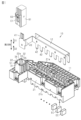
- FIG. 1 is an exploded perspective view showing a part of an electrical junction box according to an embodiment.
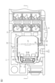
- FIG. 2 is a plan view showing a part of the electrical junction box in the same embodiment.
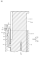
- FIG. 3 is a cross-sectional view taken along line 3-3 in FIG.
- FIG. 4 is a perspective view showing a part of the electrical component holder.
- the electrical connection box of the present disclosure comprises: [1] An electrical connection box comprising an electrical component holder and a bus bar, the bus bar being accommodated in the electrical component holder, the electrical component holder having a cylindrical connector housing into which a connector is fitted in a first direction, the bus bar having a connection portion located within the connector housing, the connection portion being connected to the connector fitted into the connector housing, the connector housing having a latching portion, and the connector having a locking portion that latches onto the latching portion in a second direction that is the opposite direction to the first direction, the connector housing having a protrusion protruding from a tip end of the connector housing in the second direction, and the connector having an abutment portion that is configured to abut against an outer surface of the protrusion.
- the abutment portion of the connector abuts against the outer surface of the protrusion in the connector housing, thereby preventing the posture of the connector mated to the connector housing from changing, in particular preventing the connector from tilting relative to the connector housing. Therefore, it is possible to prevent the connector from falling off the connector housing due to the connector tilting causing the locking portion of the connector to come off the engaging portion of the connector housing.
- connection portion may be a first connection portion
- the bus bar may have a second connection portion connected to an electrical component held in the electrical component holder, and a linking portion connecting the first connection portion and the second connection portion
- the connector housing may have a notch portion extending from the tip of the connector housing along the first direction, and the linking portion may be inserted into the notch portion along the first direction.
- the connector housing is formed with a cutout portion into which the connecting portion of the bus bar is inserted.
- This makes it possible to assemble the bus bar to the electrical component holder from the first direction.
- the cutout portion is formed to extend from the tip of the connector housing along the first direction, the connector housing is more likely to deform so that the opening at the tip opens.
- the formation of the cutout portion makes it easier for the connector to tilt relative to the connector housing.
- the abutment between the abutment portion and the protrusion suppresses the connector from tilting relative to the connector housing, so it is possible to effectively suppress the connector from falling off the connector housing even while forming the cutout portion in the connector housing.
- the engaging portion may be provided so as to protrude from the inner surface of the connector housing, and the abutting portion may be configured to be able to abut against the outer surface of the protruding portion in a direction that keeps the locking portion hooked to the engaging portion.
- the connector housing has a rectangular frame shape when viewed from the first direction, and the connector housing has a first wall portion, a second wall portion, a third wall portion, and a fourth wall portion forming each side of the rectangular frame shape, the first wall portion and the second wall portion face each other, the third wall portion and the fourth wall portion face each other, the locking portion is arranged to protrude from an inner surface of the first wall portion, the protruding portion protrudes from a tip portion of the first wall portion in the second direction, and the cutout portion may be provided in the third wall portion or the fourth wall portion.
- the connector housing is more likely to deform in the direction in which the first wall portion and the second wall portion move apart.
- the locking portion of the connector housing is provided in the first wall portion.
- the protruding portion of the connector housing in the first wall portion, it is possible to effectively prevent the locking portion of the connector from coming off the locking portion of the connector housing by the abutment between the abutting portion and the protruding portion.
- the connector housing may have a reinforcing rib protruding from the protrusion toward the inside of the connector housing.
- the reinforcing rib can improve the rigidity of the protrusion. This makes it possible to effectively suppress tilt of the connector relative to the connector housing by the abutment between the abutment portion and the protrusion.
- cylindrical as used in the description of this specification does not only refer to a shape with a continuous wall formed around the entire circumference, but also includes a shape made by combining multiple parts into a cylindrical shape, or a C-shape that has a notch cut out in part of the circumference.
- C-shape that has a notch cut out in part of the circumference.
- Cylindrical shapes include circles, ellipses, and polygons with sharp or rounded corners.
- facing in this specification refers to surfaces or components facing each other, and includes not only cases where they are completely facing each other, but also cases where they are partially facing each other.
- facing in this specification includes both cases where there is a component separate from the two parts between the two parts, and cases where there is nothing between the two parts.
- the electrical junction box 10 includes an electrical component holder 11 housed in a case (not shown) of the electrical junction box 10, and a bus bar 12 housed in the electrical component holder 11.
- the electrical junction box 10 is, for example, a relay box or a junction box mounted on a vehicle.
- the electric component holder 11 is formed of an insulating material such as synthetic resin.
- the electric component holder 11 has a holder main body 21 and a connector housing 22.
- the holder main body 21 accommodates electric components EC such as fuses and relays (not shown).
- the electric component holder 11 is called a fuse block.
- a connector C1 is fitted into the connector housing 22 from a first direction D1.
- the first direction D1 is, for example, a direction facing one side in the height direction of the electric connection box 10.
- the second direction D2 is a direction facing the other side in the height direction of the electric connection box 10, that is, the opposite direction to the first direction D1.
- a side surface on one side in the height direction of the holder main body 21 is called a first side surface 21a
- a back surface of the first side surface 21a of the holder main body 21 is called a second side surface 21b.
- the busbar 12 and a connector C1 are each attached to the electrical component holder 11 from the first side surface 21a in a first direction D1.
- the electrical components EC are attached to the holder body 21 from the second side surface 21b in a second direction D2. Note that, for example, a plurality of electrical components EC may be provided.
- the connector housing 22 is formed in a cylindrical shape into which the connector C1 can be fitted in the first direction D1.
- the connector housing 22 extends in the second direction D2 from the first side surface 21a of the holder main body 21, for example.
- the connector C1 is fitted into the inside of the connector housing 22.
- the connector housing 22 is, for example, in the shape of a rectangular frame when viewed from the first direction D1.
- Fig. 2 is a plan view of the peripheral portion of the connector housing 22 in the electrical component holder 11 when viewed from the first direction D1.
- the connector housing 22 has a first wall portion 31, a second wall portion 32, a third wall portion 33, and a fourth wall portion 34 that form each side of the rectangular frame.
- the first wall portion 31 and the second wall portion 32 face each other in a direction perpendicular to the first direction D1.
- the third wall portion 33 and the fourth wall portion 34 face each other in a direction perpendicular to the first direction D1.
- the connector housing 22 has an opening 22a at its tip in the second direction D2, into which the connector C1 is inserted.
- the opening 22a opens in the second direction D2.
- the connector housing 22 has a cutout portion 35.
- the cutout portion 35 extends linearly along the first direction D1 from the tip of the third wall portion 33 in the second direction D2, for example.
- the cutout portion 35 is formed so as to penetrate the third wall portion 33.
- the connector housing 22 has a locking portion 36.
- the locking portion 36 is provided, for example, so as to protrude from the inner surface of the first wall portion 31.
- the locking portion 36 is configured to be able to lock with a locking portion 62 provided on the connector C1.
- the locking portion 62 hooks onto the locking portion 36 in the second direction D2, thereby maintaining the connector C1 fitted inside the connector housing 22.
- the bus bar 12 is made of a conductor such as metal.
- the bus bar 12 is formed, for example, by pressing a metal plate.
- the bus bar 12 is attached to the holder main body 21 from the first side surface 21a side along the first direction D1.
- the electric components EC are attached to the holder main body 21 from the second side surface 21b side.
- the bus bar 12 has a first connection portion 41 connected to the connector C1, a second connection portion 42 connected to an electrical component EC held in the holder main body 21, and a linking portion 43 connecting the first connection portion 41 and the second connection portion 42.
- the second connection portion 42 is housed in the holder main body 21.
- a plurality of second connection portions 42 are provided corresponding to a plurality of electrical components EC, for example.
- the connecting portion 43 is inserted in the first direction D1 into the cutout portion 35 provided in the third wall portion 33 of the connector housing 22.
- the connecting portion 43 extends from the outside of the connector housing 22 in the holder main body portion 21 to the inside of the connector housing 22 through the cutout portion 35.
- the first connection portion 41 is located inside the connector housing 22.
- the first connection portion 41 extends in the second direction D2 inside the connector housing 22.
- the first connection portion 41 is connected to the connector C1 fitted into the connector housing 22.
- the connector housing 22 has a protrusion 51 that protrudes from a tip end of the connector housing 22 in the second direction D2.
- the protrusion 51 is provided on, for example, the first wall portion 31. That is, the protrusion 51 protrudes from a tip end of the first wall portion 31 in the second direction D2.
- the width of the protrusion 51 is set to be smaller than the width of the first wall portion 31, for example.
- the connector housing 22 has reinforcing ribs 52 that protrude from the protrusion 51 toward the inside of the connector housing 22.
- the two reinforcing ribs 52 protrude, for example, from both ends of the width direction of the protrusion 51 toward the inside of the connector housing 22.
- each reinforcing rib 52 extends linearly along the first direction D1.
- each reinforcing rib 52 extends from the protrusion 51 to the bottom of the connector housing 22. In this way, with the two reinforcing ribs 52 formed, the protrusion 51 is approximately U-shaped when viewed from the first direction D1.
- the connector C1 has a connector case 61. Terminals (not shown) connected to the first connection portions 41 of the bus bars 12 are housed inside the connector case 61.
- Terminals (not shown) connected to the first connection portions 41 of the bus bars 12 are housed inside the connector case 61.
- the internal structure of the connector case 61 is shown in a simplified form in Fig. 3.
- the connector C1 includes electric wires (not shown) connected to the terminals.
- the connector case 61 has the locking portion 62 and the abutment portion 63.
- the locking portion 62 is an elastic piece extending from the connector case 61.
- the locking portion 62 has elasticity capable of pressing the first wall portion 31 of the connector housing 22.
- the locking portion 62 has a locking protrusion 64.
- the abutment portion 63 is formed, for example, to connect a pair of base portions 65 protruding from the connector case 61.
- the protrusions 51 of the connector housing 22 are inserted into the inner space formed by the base portions 65 and the abutment portions 63.
- the abutment portions 63 are configured to be able to abut against the outer surface of the protrusions 51 in the direction D3 in which the locking portion 62 moves away from the engaging portion 36.
- the abutment portions 63 are configured to be able to abut against the outer surface of the protrusions 51 in a direction that keeps the locking portion 62 hooked onto the engaging portion 36.
- a notch 35 is formed in the third wall portion 33. This makes it possible to assemble the bus bar 12 including the first connection portion 41 disposed in the connector housing 22 from the first side surface 21 a side of the holder main body 21 along the first direction D1.
- the rigidity of the connector housing 22 may decrease. Specifically, by providing the cutout portion 35 in the third wall portion 33, the connector housing 22 becomes more likely to deform in a direction in which the first wall portion 31 and the second wall portion 32 move apart. Furthermore, since the locking portion 36 is provided in the first wall portion 31, if no measures are taken, there is a risk that the locking portion 36 and the locking portion 62 of the connector C1 may come loose when the connector housing 22 deforms in a direction in which the first wall portion 31 and the second wall portion 32 move apart.
- the abutting portion 63 of the connector C1 is abutted against the outer surface of the protrusion 51 provided in the first wall portion 31, thereby preventing the connector C1 from tilting in the arrow direction D4 relative to the connector housing 22 due to an external force, etc.
- the engagement between the engaging portion 36 and the locking portion 62 is prevented from unintentionally coming loose, preventing the connector C1 from falling off the connector housing 22.
- the connector housing 22 has a protruding portion 51 that protrudes from a tip end of the connector housing 22 in the second direction D2.
- the abutting portion 63 provided on the connector C1 is configured to be able to abut against an outer surface of the protruding portion 51. According to this configuration, the abutting portion 63 of the connector C1 abuts against the outer surface of the protruding portion 51 of the connector housing 22, thereby suppressing a change in the posture of the connector C1 fitted into the connector housing 22, in particular, suppressing the connector C1 from tilting with respect to the connector housing 22. Therefore, it is possible to suppress a situation in which the locking portion 62 of the connector C1 comes off the engaging portion 36 of the connector housing 22 due to the connector C1 tilting, causing the connector C1 to fall off the connector housing 22.
- the bus bar 12 has a first connection portion 41 connected to the connector C1, a second connection portion 42 connected to an electrical component EC held in the electrical component holder 11, and a connecting portion 43 connecting the first connection portion 41 and the second connection portion 42.
- the connector housing 22 has a cutout portion 35 extending from the tip of the connector housing 22 along the first direction D1.
- the connecting portion 43 of the bus bar 12 is inserted into the cutout portion 35 along the first direction D1. According to this configuration, the connector housing 22 is formed with the cutout portion 35 into which the connecting portion 43 of the bus bar 12 is inserted. This makes it possible to assemble the bus bar 12 to the electrical component holder 11 from the first direction D1.
- the cutout portion 35 is formed to extend from the tip of the connector housing 22 along the first direction D1, the connector housing 22 is easily deformed so that the opening 22a at the tip portion opens. That is, the formation of the cutout portion 35 makes it easier for the connector C1 to tilt relative to the connector housing 22.
- the abutment between the abutment portion 63 and the protrusion 51 described above suppresses the tilt of the connector C1 relative to the connector housing 22, so it is possible to effectively suppress the connector C1 from falling off even while forming the cutout portion 35 in the connector housing 22.
- the locking portion 36 is provided to protrude from the inner surface of the connector housing 22.
- the abutment portion 63 is configured to be able to abut against the outer surface of the protrusion 51 in the direction D3 in which the locking portion 62 moves away from the locking portion 36.
- the abutment portion 63 is configured to be able to abut against the outer surface of the protrusion 51 in a direction that keeps the locking portion 62 hooked onto the locking portion 36.
- the connector housing 22 has a rectangular frame shape when viewed from the first direction D1.
- the connector housing 22 has a first wall portion 31, a second wall portion 32, a third wall portion 33, and a fourth wall portion 34 that form each side of the rectangular frame shape.
- the first wall portion 31 and the second wall portion 32 face each other.
- the third wall portion 33 and the fourth wall portion 34 face each other.
- the locking portion 36 is provided to protrude from the inner surface of the first wall portion 31.
- the protrusion portion 51 protrudes from the tip end of the first wall portion 31 in the second direction D2.
- the cutout portion 35 is provided in the third wall portion 33.
- the connector housing 22 is easily deformed in a direction in which the first wall portion 31 and the second wall portion 32 move away from each other.
- the locking portion 36 of the connector housing 22 is provided on the first wall portion 31.
- the connector housing 22 has a reinforcing rib 52 that protrudes from the protrusion 51 toward the inside of the connector housing 22.
- the reinforcing rib 52 can improve the rigidity of the protrusion 51.
- the inclination of the connector C1 relative to the connector housing 22 can be effectively suppressed by the abutment between the abutment portion 63 and the protrusion 51.
- the number of the reinforcing ribs 52 in the connector housing 22 is not limited to the above embodiment, and may be changed as appropriate depending on the configuration.
- the cutout portion 35 may be formed in the fourth wall portion 34 instead of the third wall portion 33. Also, the cutout portion 35 may be formed in the first wall portion 31 or the second wall portion 32.
- the locking portion 36 may be provided on any one of the second wall portion 32 , the third wall portion 33 and the fourth wall portion 34 instead of the first wall portion 31 .
- the protrusion 51 may be provided on any one of the second wall portion 32 , the third wall portion 33 and the fourth wall portion 34 , instead of the first wall portion 31 .
- the electrical components EC housed in the electrical component holder 11 are not limited to the above embodiment, and may include electrical components other than fuses and relays. Furthermore, the electrical components EC may be composed only of electrical components other than fuses and relays.
- the illustrated non-limiting embodiment of the electrical junction box 10 is an example of a vehicle-mounted electrical junction box.
- the connector C1 is an example of a connector plug.
- the illustrated non-limiting embodiment of the connector housing 22 is an example of a connector socket configured to receive the connector C1.
- the first direction D1 is an example of a normal mounting direction of the connector C1 to the connector housing 22.
- the second direction D2 is an example of a normal removal direction of the connector C1 from the connector housing 22.
- the third direction D3 is an example of an irregular movement direction different from the normal mounting direction and the normal removal direction.
- the third direction D3 may be a radial direction of the connector housing 22 (socket).
- the height direction of the illustrated non-limiting embodiment may be referred to as the depth direction of the connector housing 22 (socket).
- the pair of the engaging portion 36 of the connector housing 22 and the locking portion 62 of the connector C1 is an example of a pair of a first socket side stopper and a first plug side stopper configured to prevent or minimize movement of the connector C1 in the normal removal direction from the connector housing 22, for example, by engaging with each other in the second direction D2.
- a first socket side stopper and a first plug side stopper configured to prevent or minimize movement of the connector C1 in the normal removal direction from the connector housing 22, for example, by engaging with each other in the second direction D2.
- the pair of the protruding portion 51 of the connector housing 22 and the abutting portion 63 of the connector C1 is an example of a pair of a second socket side stopper and a second plug side stopper configured to maintain the mutual engagement between the engaging portion 36 of the connector housing 22 and the locking portion 62 of the connector C1, for example, by contacting each other in the third direction D3, or by preventing or minimizing movement of the connector C1 in the abnormal movement direction relative to the connector housing 22.
- the set of first connection portion 41 and second connection portion 42 of bus bar 12 may be referred to as a set of input terminal and output terminal of bus bar 12 .
- the embodiments and modified examples disclosed herein are illustrative in all respects, and the present invention is not limited to these examples. That is, the scope of the present invention is defined by the claims, and it is intended to include all modifications within the meaning and scope of the claims.
- Electrical junction box 11 Electrical component holder 12 Bus bar 21 Holder main body 21a First side surface 21b Second side surface 22 Connector housing 22a Opening 31 First wall portion 32 Second wall portion 33 Third wall portion 34 Fourth wall portion 35 Notch portion 36 Locking portion 41 First connection portion (connection portion) 42 Second connection portion 43 Linking portion 51 Protrusion 52 Reinforcing rib 61 Connector case 62 Locking portion 63 Contact portion 64 Locking protrusion 65 Base portion C1 Connector EC Electrical component D1 First direction D2 Second direction
Landscapes
- Engineering & Computer Science (AREA)
- Architecture (AREA)
- Civil Engineering (AREA)
- Structural Engineering (AREA)
- Mechanical Engineering (AREA)
- Connection Or Junction Boxes (AREA)
Abstract
電気接続箱は、電気部品ホルダ(11)と、バスバー(12)と、を備える。バスバー(12)は、電気部品ホルダ(11)に収容される。電気部品ホルダ(11)は、コネクタ(C1)が第1方向(D1)に嵌合される筒状のコネクタハウジング(22)を有する。コネクタ(C1)は、コネクタハウジング(22)の係止部(36)に対し、第1方向(D1)の反対方向である第2方向(D2)に引っ掛かるロック部(62)を有する。コネクタハウジング(22)は、コネクタハウジング(22)における第2方向(D2)の先端部から突出する突出部(51)を有する。コネクタ(C1)は、当接部(63)を有する。突出部(51)は、当接部(63)が突出部(51)の外側面に当接可能に構成されている。
Description
本開示は、電気接続箱に関するものである。
特許文献1には、ケースと、電気部品ホルダと、バスバーと、を備える電気接続箱が開示されている。電気部品ホルダは、ケースに収容される。バスバーは、電気部品ホルダに収容されるとともに、電気部品ホルダに保持された電気部品に接続される。電気部品ホルダは、コネクタが嵌合される筒状のコネクタハウジングを有する。バスバーは、コネクタハウジング内に位置する接続部を有する。バスバーの接続部は、コネクタハウジングに嵌合されるコネクタと接続される。コネクタは、コネクタハウジングに設けられた係止部に対して引っ掛かるロック部を有する。コネクタのロック部とコネクタハウジングの係止部との引っ掛かりによって、コネクタハウジングに対するコネクタの装着状態が保持される。
上記のような電気接続箱では、コネクタハウジングに嵌合されたコネクタの姿勢が変化することで、例えば、コネクタがコネクタハウジングに対して傾くことでロック部が係止部から外れる懸念がある。この場合、コネクタがコネクタハウジングから脱落するおそれがあった。
本開示の目的は、コネクタの脱落を抑制可能とした電気接続箱を提供することにある。
本開示の電気接続箱は、電気部品ホルダと、バスバーと、を備える電気接続箱であって、前記バスバーは、前記電気部品ホルダに収容され、前記電気部品ホルダは、コネクタが第1方向に嵌合される筒状のコネクタハウジングを有し、前記バスバーは、前記コネクタハウジング内に位置する接続部を有し、前記接続部は、前記コネクタハウジングに嵌合される前記コネクタと接続され、前記コネクタハウジングは、係止部を有し、前記コネクタは、前記係止部に対し、前記第1方向の反対方向である第2方向に引っ掛かるロック部を有し、前記コネクタハウジングは、前記コネクタハウジングにおける前記第2方向の先端部から突出する突出部を有し、前記コネクタは、当接部を有し、前記当接部は、前記突出部の外側面に当接可能に構成されている。
本開示の電気接続箱によれば、コネクタの脱落を抑制することが可能となる。
[本開示の実施形態の説明]
最初に本開示の実施態様を列記して説明する。
本開示の電気接続箱は、
[1]電気部品ホルダと、バスバーと、を備える電気接続箱であって、前記バスバーは、前記電気部品ホルダに収容され、前記電気部品ホルダは、コネクタが第1方向に嵌合される筒状のコネクタハウジングを有し、前記バスバーは、前記コネクタハウジング内に位置する接続部を有し、前記接続部は、前記コネクタハウジングに嵌合される前記コネクタと接続され、前記コネクタハウジングは、係止部を有し、前記コネクタは、前記係止部に対し、前記第1方向の反対方向である第2方向に引っ掛かるロック部を有し、前記コネクタハウジングは、前記コネクタハウジングにおける前記第2方向の先端部から突出する突出部を有し、前記コネクタは、当接部を有し、前記当接部は、前記突出部の外側面に当接可能に構成されている。
この構成によれば、コネクタの当接部がコネクタハウジングにおける突出部の外側面に当接することにより、コネクタハウジングに嵌合されたコネクタの姿勢が変化すること、特に、コネクタがコネクタハウジングに対して傾くことが抑制される。したがって、コネクタが傾くことによりコネクタのロック部がコネクタハウジングの係止部から外れて、コネクタがコネクタハウジングから脱落することを抑制することが可能となる。
[2]上記[1]において、前記接続部を第1接続部として、前記バスバーは、前記電気部品ホルダに保持される電気部品に接続される第2接続部と、前記第1接続部と前記第2接続部とを繋ぐ連結部と、を有し、前記コネクタハウジングは、前記コネクタハウジングの前記先端部から前記第1方向に沿って延びる切り欠き部を有し、前記連結部は、前記第1方向に沿って前記切り欠き部に挿入されていてもよい。
この構成によれば、コネクタハウジングには、バスバーの連結部が挿入される切り欠き部が形成される。これにより、電気部品ホルダに対してバスバーを第1方向から組み付けることが可能となる。また、切り欠き部は、コネクタハウジングの先端部から第1方向に沿って延びるように形成されるため、コネクタハウジングは先端部の開口が開くように変形しやすくなる。すなわち、切り欠き部が形成されることにより、コネクタがコネクタハウジングに対して傾きやすくなる。その点、上記の当接部と突出部との当接により、コネクタハウジングに対するコネクタの傾きが抑制されるため、コネクタハウジングに切り欠き部を形成しつつも、コネクタがコネクタハウジングから脱落することを効果的に抑制することが可能となる。
[3]上記[2]において、前記係止部は、前記コネクタハウジングの内側面から突出するように設けられており、前記当接部は、前記突出部の外側面に対して、前記係止部に対する前記ロック部の引っ掛かりを保持する方向に当接可能に構成されていてもよい。
この構成によれば、コネクタのロック部がコネクタハウジングの係止部から外れることを、当接部と突出部との当接によって効果的に抑制することが可能となる。
[4]上記[3]において、前記コネクタハウジングは、前記第1方向から見て四角枠状をなし、前記コネクタハウジングは、前記四角枠状の各辺をなす第1壁部と、第2壁部と、第3壁部と、第4壁部と、を有し、前記第1壁部と前記第2壁部とは、互いに対向し、前記第3壁部と前記第4壁部とは、互いに対向し、前記係止部は、前記第1壁部の内側面から突出するように設けられており、前記突出部は、前記第1壁部における前記第2方向の先端部から突出しており、前記切り欠き部は、前記第3壁部または前記第4壁部に設けられていてもよい。
[4]上記[3]において、前記コネクタハウジングは、前記第1方向から見て四角枠状をなし、前記コネクタハウジングは、前記四角枠状の各辺をなす第1壁部と、第2壁部と、第3壁部と、第4壁部と、を有し、前記第1壁部と前記第2壁部とは、互いに対向し、前記第3壁部と前記第4壁部とは、互いに対向し、前記係止部は、前記第1壁部の内側面から突出するように設けられており、前記突出部は、前記第1壁部における前記第2方向の先端部から突出しており、前記切り欠き部は、前記第3壁部または前記第4壁部に設けられていてもよい。
この構成によれば、切り欠き部が第3壁部または第4壁部に設けられるため、コネクタハウジングは、第1壁部と第2壁部とが離れる方向に変形しやすくなる。また、コネクタハウジングの係止部は、第1壁部に設けられる。それに対し、コネクタハウジングの突出部を第1壁部に設けることで、コネクタのロック部がコネクタハウジングの係止部から外れることを、当接部と突出部との当接によって効果的に抑制することが可能となる。
[5]上記[1]から[4]のいずれかにおいて、前記コネクタハウジングは、前記突出部から前記コネクタハウジングの内側に向かって突出する補強リブを有していてもよい。
この構成によれば、補強リブによって突出部の剛性を向上させることが可能となる。これにより、コネクタハウジングに対するコネクタの傾きを、当接部と突出部との当接によって好適に抑制することが可能となる。
[本開示の実施形態の詳細]
本開示の電気接続箱の具体例を、以下に図面を参照しつつ説明する。各図面では、説明の便宜上、構成の一部を誇張または簡略化して示す場合がある。また、各部分の寸法比率については各図面で異なる場合がある。
本開示の電気接続箱の具体例を、以下に図面を参照しつつ説明する。各図面では、説明の便宜上、構成の一部を誇張または簡略化して示す場合がある。また、各部分の寸法比率については各図面で異なる場合がある。
なお、本明細書の説明で使用される「筒状」は、周方向全周にわたって連続して周壁が形成されたものだけではなく、複数の部品を組み合わせて筒状をなすものや、C字状のように周方向の一部に切り欠きなどを有するものも含む。また、「筒状」の形状には、円形、楕円形、及び、尖ったまたは丸い角を有する多角形が含まれる。
また、本明細書における「対向」とは、面同士又は部材同士が互いに正面の位置にあることを指し、互いが完全に正面の位置にある場合だけでなく、互いが部分的に正面の位置にある場合を含む。また、本明細書における「対向」とは、2つの部分の間に、2つの部分とは別の部材が介在している場合と、2つの部分の間に何も介在していない場合の両方を含む。
(電気接続箱10)
図1に示すように、電気接続箱10は、電気接続箱10の図示しないケースに収容される電気部品ホルダ11と、電気部品ホルダ11に収容されるバスバー12と、を備える。電気接続箱10は、例えば、車両に搭載されるリレーボックスやジャンクションボックスである。
図1に示すように、電気接続箱10は、電気接続箱10の図示しないケースに収容される電気部品ホルダ11と、電気部品ホルダ11に収容されるバスバー12と、を備える。電気接続箱10は、例えば、車両に搭載されるリレーボックスやジャンクションボックスである。
(電気部品ホルダ11)
電気部品ホルダ11は、合成樹脂等の絶縁体にて形成されている。電気部品ホルダ11は、ホルダ本体部21と、コネクタハウジング22とを有している。ホルダ本体部21には、図示しないヒューズやリレー等の電気部品ECが収容されている。なお、電気部品ECにヒューズが含まれる場合、電気部品ホルダ11はヒューズブロックと称される。コネクタハウジング22には、第1方向D1からコネクタC1が嵌合される。なお、第1方向D1は、例えば、電気接続箱10の高さ方向の一方側を向く方向である。また、第2方向D2は、電気接続箱10の高さ方向の他方側を向く方向、すなわち、第1方向D1の反対方向である。また、以下の説明では、ホルダ本体部21における高さ方向の一方側の側面を第1側面21aと称し、ホルダ本体部21における第1側面21aの裏面を第2側面21bと称する。バスバー12および後述するコネクタC1の各々は、電気部品ホルダ11に対して第1側面21a側から第1方向D1に沿って組み付けられる。電気部品ECは、ホルダ本体部21に対して第2側面21b側から第2方向D2に沿って組み付けられる。なお、電気部品ECは、例えば複数設けられる。
電気部品ホルダ11は、合成樹脂等の絶縁体にて形成されている。電気部品ホルダ11は、ホルダ本体部21と、コネクタハウジング22とを有している。ホルダ本体部21には、図示しないヒューズやリレー等の電気部品ECが収容されている。なお、電気部品ECにヒューズが含まれる場合、電気部品ホルダ11はヒューズブロックと称される。コネクタハウジング22には、第1方向D1からコネクタC1が嵌合される。なお、第1方向D1は、例えば、電気接続箱10の高さ方向の一方側を向く方向である。また、第2方向D2は、電気接続箱10の高さ方向の他方側を向く方向、すなわち、第1方向D1の反対方向である。また、以下の説明では、ホルダ本体部21における高さ方向の一方側の側面を第1側面21aと称し、ホルダ本体部21における第1側面21aの裏面を第2側面21bと称する。バスバー12および後述するコネクタC1の各々は、電気部品ホルダ11に対して第1側面21a側から第1方向D1に沿って組み付けられる。電気部品ECは、ホルダ本体部21に対して第2側面21b側から第2方向D2に沿って組み付けられる。なお、電気部品ECは、例えば複数設けられる。
(コネクタハウジング22)
コネクタハウジング22は、コネクタC1を第1方向D1において嵌合可能な筒状に形成されている。コネクタハウジング22は、例えば、ホルダ本体部21の第1側面21aから第2方向D2に延出している。コネクタC1は、コネクタハウジング22の内側に嵌合される。
コネクタハウジング22は、コネクタC1を第1方向D1において嵌合可能な筒状に形成されている。コネクタハウジング22は、例えば、ホルダ本体部21の第1側面21aから第2方向D2に延出している。コネクタC1は、コネクタハウジング22の内側に嵌合される。
図2および図4に示すように、コネクタハウジング22は、例えば、第1方向D1から見て四角枠状をなす。なお、図2は、電気部品ホルダ11におけるコネクタハウジング22の周辺部分を、第1方向D1から見た平面図である。コネクタハウジング22は、四角枠状の各辺をなす第1壁部31と、第2壁部32と、第3壁部33と、第4壁部34と、を有する。第1壁部31と第2壁部32とは、第1方向D1に対する垂直な方向において互いに対向する。第3壁部33と第4壁部34とは、第1方向D1に対する垂直な方向において互いに対向する。コネクタハウジング22は、その第2方向D2の先端部において、コネクタC1が挿入される開口22aを有している。開口22aは、第2方向D2に開口している。
コネクタハウジング22は、切り欠き部35を有する。切り欠き部35は、例えば、第3壁部33における第2方向D2の先端部から第1方向D1に沿って直線状に延びている。切り欠き部35は、第3壁部33を貫通するように形成されている。
コネクタハウジング22は、係止部36を有する。係止部36は、例えば、第1壁部31の内側面から突出するように設けられている。係止部36は、コネクタC1に設けられたロック部62に係止可能に構成されている。ロック部62が係止部36に対して第2方向D2に引っ掛かることで、コネクタC1がコネクタハウジング22の内側に嵌合された状態が保持される。
(バスバー12)
バスバー12は、金属等の導体にて形成されている。バスバー12は、例えば、金属板からプレス加工によって形成されている。バスバー12は、第1方向D1に沿って、ホルダ本体部21の第1側面21a側から組み付けられる。また、ホルダ本体部21には、電気部品ECが第2側面21b側から組み付けられる。
バスバー12は、金属等の導体にて形成されている。バスバー12は、例えば、金属板からプレス加工によって形成されている。バスバー12は、第1方向D1に沿って、ホルダ本体部21の第1側面21a側から組み付けられる。また、ホルダ本体部21には、電気部品ECが第2側面21b側から組み付けられる。
図1に示すように、バスバー12は、コネクタC1に接続される第1接続部41と、ホルダ本体部21に保持される電気部品ECに接続される第2接続部42と、第1接続部41と第2接続部42とを繋ぐ連結部43と、を有する。第2接続部42は、ホルダ本体部21に収容される。第2接続部42は、例えば、複数の電気部品ECに対応して複数設けられている。
連結部43は、コネクタハウジング22の第3壁部33に設けられた切り欠き部35に対して、第1方向D1に沿って挿入されている。連結部43は、切り欠き部35を通じて、ホルダ本体部21におけるコネクタハウジング22の外側からコネクタハウジング22の内側まで延びている。第1接続部41は、コネクタハウジング22内に位置する。第1接続部41は、コネクタハウジング22の内側において第2方向D2に延出している。第1接続部41は、コネクタハウジング22に嵌合されたコネクタC1と接続される。
(突出部51)
図3および図4に示すように、コネクタハウジング22は、コネクタハウジング22の第2方向D2の先端部から突出する突出部51を有している。突出部51は、例えば、第1壁部31に設けられている。すなわち、突出部51は、第1壁部31における第2方向D2の先端部から突出している。突出部51の幅は、例えば、第1壁部31の幅よりも小さく設定されている。
図3および図4に示すように、コネクタハウジング22は、コネクタハウジング22の第2方向D2の先端部から突出する突出部51を有している。突出部51は、例えば、第1壁部31に設けられている。すなわち、突出部51は、第1壁部31における第2方向D2の先端部から突出している。突出部51の幅は、例えば、第1壁部31の幅よりも小さく設定されている。
コネクタハウジング22は、突出部51からコネクタハウジング22の内側に向かって突出する補強リブ52を有している。補強リブ52は、例えば2つ設けられている。2つの補強リブ52は、例えば、突出部51の幅方向両端からコネクタハウジング22の内側に向かって突出している。各補強リブ52は、例えば、第1方向D1に沿って直線状に延びている。また、各補強リブ52は、突出部51からコネクタハウジング22の底部にまで延びている。このように、2つの補強リブ52が形成されていることで、突出部51は、第1方向D1から見て略U字状をなしている。
(コネクタC1)
コネクタC1は、コネクタケース61を有している。コネクタケース61の内部には、バスバー12の第1接続部41に接続される図示しない端子が収容されている。なお、図3では、説明の便宜上、コネクタケース61の内部構造を簡略化して図示している。コネクタC1は、前記端子に接続された図示しない電線を備える。
コネクタC1は、コネクタケース61を有している。コネクタケース61の内部には、バスバー12の第1接続部41に接続される図示しない端子が収容されている。なお、図3では、説明の便宜上、コネクタケース61の内部構造を簡略化して図示している。コネクタC1は、前記端子に接続された図示しない電線を備える。
図3に示すように、コネクタケース61は、前記ロック部62と、当接部63とを有している。ロック部62は、コネクタケース61から延出する弾性片である。ロック部62は、コネクタハウジング22の第1壁部31を押圧可能な弾性を有している。ロック部62は、係止凸部64を有している。コネクタケース61がコネクタハウジング22の内側に嵌合された状態において、ロック部62の係止凸部64は、コネクタハウジング22の係止部36に対して第2方向D2に引っ掛かるようになっている。これにより、コネクタケース61がコネクタハウジング22の内側に嵌合された状態が保持される。
図2に示すように、当接部63は、例えば、コネクタケース61から突出する一対の基部65を繋ぐように形成されている。コネクタケース61がコネクタハウジング22の内側に嵌合された状態において、コネクタハウジング22の突出部51は、各基部65と当接部63とによって形成される内側のスペースに挿入される。これにより、当接部63は、突出部51の外側面に当接可能となる。詳しくは、当接部63は、突出部51の外側面に対して、ロック部62が係止部36から離れる方向D3に当接可能に構成されている。すなわち、当接部63は、突出部51の外側面に対して、係止部36に対するロック部62の引っ掛かりを保持する方向に当接可能に構成されている。
本実施形態の作用について説明する。
本実施形態のコネクタハウジング22では、第3壁部33に切り欠き部35が形成されている。これにより、コネクタハウジング22内に配置される第1接続部41を含むバスバー12を、第1方向D1に沿って、ホルダ本体部21の第1側面21a側から組み付けることが可能となっている。
本実施形態のコネクタハウジング22では、第3壁部33に切り欠き部35が形成されている。これにより、コネクタハウジング22内に配置される第1接続部41を含むバスバー12を、第1方向D1に沿って、ホルダ本体部21の第1側面21a側から組み付けることが可能となっている。
しかしながら、コネクタハウジング22の第3壁部33に切り欠き部35を設けることで、コネクタハウジング22の剛性は低下する懸念がある。具体的には、第3壁部33に切り欠き部35を設けることで、コネクタハウジング22は、第1壁部31と第2壁部32とが離れる方向に変形しやすくなる。そして、係止部36が第1壁部31に設けられるため、何ら対策を講じなければ、第1壁部31と第2壁部32とが離れる方向にコネクタハウジング22が変形したとき、係止部36とコネクタC1のロック部62との引っ掛かりが外れるおそれがある。そこで、本実施形態では、第1壁部31に設けた突出部51の外側面にコネクタC1の当接部63を当接させることで、外力等によりコネクタC1がコネクタハウジング22に対して矢印方向D4に傾くことを抑制している。その結果、係止部36とロック部62との引っ掛かりが意図せずに外れて、コネクタC1がコネクタハウジング22から脱落することが抑制されている。
本実施形態の効果について説明する。
(1)コネクタハウジング22は、コネクタハウジング22における第2方向D2の先端部から突出する突出部51を有する。コネクタC1に設けられた当接部63は、突出部51の外側面に当接可能に構成されている。この構成によれば、コネクタC1の当接部63がコネクタハウジング22における突出部51の外側面に当接することにより、コネクタハウジング22に嵌合されたコネクタC1の姿勢が変化すること、特に、コネクタC1がコネクタハウジング22に対して傾くことが抑制される。したがって、コネクタC1が傾くことによりコネクタC1のロック部62がコネクタハウジング22の係止部36から外れて、コネクタC1がコネクタハウジング22から脱落することを抑制することが可能となる。
(1)コネクタハウジング22は、コネクタハウジング22における第2方向D2の先端部から突出する突出部51を有する。コネクタC1に設けられた当接部63は、突出部51の外側面に当接可能に構成されている。この構成によれば、コネクタC1の当接部63がコネクタハウジング22における突出部51の外側面に当接することにより、コネクタハウジング22に嵌合されたコネクタC1の姿勢が変化すること、特に、コネクタC1がコネクタハウジング22に対して傾くことが抑制される。したがって、コネクタC1が傾くことによりコネクタC1のロック部62がコネクタハウジング22の係止部36から外れて、コネクタC1がコネクタハウジング22から脱落することを抑制することが可能となる。
(2)バスバー12は、コネクタC1に接続される第1接続部41と、電気部品ホルダ11に保持される電気部品ECに接続される第2接続部42と、第1接続部41と第2接続部42とを繋ぐ連結部43と、を有する。コネクタハウジング22は、コネクタハウジング22の先端部から第1方向D1に沿って延びる切り欠き部35を有する。バスバー12の連結部43は、第1方向D1に沿って切り欠き部35に挿入されている。この構成によれば、コネクタハウジング22には、バスバー12の連結部43が挿入される切り欠き部35が形成される。これにより、電気部品ホルダ11に対してバスバー12を第1方向D1から組み付けることが可能となる。また、切り欠き部35は、コネクタハウジング22の先端部から第1方向D1に沿って延びるように形成されるため、コネクタハウジング22は先端部の開口22aが開くように変形しやすくなる。すなわち、切り欠き部35が形成されることにより、コネクタC1がコネクタハウジング22に対して傾きやすくなる。その点、上記の当接部63と突出部51との当接により、コネクタハウジング22に対するコネクタC1の傾きが抑制されるため、コネクタハウジング22に切り欠き部35を形成しつつも、コネクタC1の脱落を効果的に抑制することが可能となる。
(3)係止部36は、コネクタハウジング22の内側面から突出するように設けられている。当接部63は、突出部51の外側面に対して、ロック部62が係止部36から離れる方向D3に当接可能に構成されている。すなわち、当接部63は、突出部51の外側面に対して、係止部36に対するロック部62の引っ掛かりを保持する方向に当接可能に構成されている。この構成によれば、コネクタC1のロック部62がコネクタハウジング22の係止部36から外れることを、当接部63と突出部51との当接によって効果的に抑制することが可能となる。
(4)コネクタハウジング22は、第1方向D1から見て四角枠状をなす。コネクタハウジング22は、四角枠状の各辺をなす第1壁部31と、第2壁部32と、第3壁部33と、第4壁部34と、を有する。第1壁部31と第2壁部32とは、互いに対向する。第3壁部33と第4壁部34とは、互いに対向する。係止部36は、第1壁部31の内側面から突出するように設けられている。突出部51は、第1壁部31における第2方向D2の先端部から突出している。切り欠き部35は、第3壁部33に設けられている。この構成によれば、切り欠き部35が第3壁部33に設けられるため、コネクタハウジング22は、第1壁部31と第2壁部32とが離れる方向に変形しやすくなる。また、コネクタハウジング22の係止部36は、第1壁部31に設けられる。それに対し、コネクタハウジング22の突出部51を第1壁部31に設けることで、コネクタC1のロック部62がコネクタハウジング22の係止部36から外れることを、当接部63と突出部51との当接によって効果的に抑制することが可能となる。
(5)コネクタハウジング22は、突出部51からコネクタハウジング22の内側に向かって突出する補強リブ52を有している。この構成によれば、補強リブ52によって突出部51の剛性を向上させることが可能となる。これにより、コネクタハウジング22に対するコネクタC1の傾きを、当接部63と突出部51との当接によって好適に抑制することが可能となる。
(変更例)
本実施形態は、以下のように変更して実施することができる。本実施形態及び以下の変更例は、技術的に矛盾しない範囲で互いに組み合わせて実施することができる。
本実施形態は、以下のように変更して実施することができる。本実施形態及び以下の変更例は、技術的に矛盾しない範囲で互いに組み合わせて実施することができる。
・コネクタハウジング22において、補強リブ52の個数等の構成は上記実施形態に限定されるものではなく、構成に応じて適宜変更してもよい。
・コネクタハウジング22において、第3壁部33ではなく第4壁部34に切り欠き部35が形成されていてもよい。また、切り欠き部35が第1壁部31または第2壁部32に形成されていてもよい。
・コネクタハウジング22において、第3壁部33ではなく第4壁部34に切り欠き部35が形成されていてもよい。また、切り欠き部35が第1壁部31または第2壁部32に形成されていてもよい。
・コネクタハウジング22において、第1壁部31ではなく、第2壁部32、第3壁部33および第4壁部34のいずれかに係止部36が設けられていてもよい。
・コネクタハウジング22において、第1壁部31ではなく、第2壁部32、第3壁部33および第4壁部34のいずれかに突出部51が設けられていてもよい。
・コネクタハウジング22において、第1壁部31ではなく、第2壁部32、第3壁部33および第4壁部34のいずれかに突出部51が設けられていてもよい。
・電気部品ホルダ11に収容される電気部品ECは、上記実施形態に限定されるものではなく、ヒューズやリレー以外の電気部品を含む構成であってもよい。また、電気部品ECは、ヒューズやリレー以外の電気部品のみから構成されていてもよい。
・図示した非限定的実施形態の電気接続箱10は、車両搭載式の電気接続箱の一例である。図示した非限定的実施形態において、コネクタC1はコネクタプラグの一例である。図示した非限定的実施形態のコネクタハウジング22は、コネクタC1を受け取るように構成されたコネクタソケットの一例である。図示した非限定的実施形態において、第1方向D1は、コネクタハウジング22に対するコネクタC1の正規取付方向の一例である。第2方向D2は、コネクタハウジング22からのコネクタC1の正規取り外し方向の一例である。第3方向D3は、正規取付方向および正規取り外し方向とは異なる非正規移動方向の一例である。第3方向D3は、コネクタハウジング22(ソケット)の径方向であってよい。図示した非限定的実施形態の高さ方向は、コネクタハウジング22(ソケット)の深さ方向と称することがある。
・図3に示す非限定的実施形態において、コネクタハウジング22の係止部36とコネクタC1のロック部62とのペアは、例えば第2方向D2において相互係合することで、コネクタハウジング22からのコネクタC1の正規取り外し方向への移動を防止または最小化するように構成された、第1のソケット側ストッパと第1のプラグ側ストッパとのペアの一例である。図3に示す非限定的実施形態において、コネクタハウジング22の突出部51とコネクタC1の当接部63とのペアは、例えば第3方向D3において相互接触することで、または、コネクタハウジング22に対するコネクタC1の非正規移動方向への移動を防止または最小化することで、コネクタハウジング22の係止部36とコネクタC1のロック部62との相互係合を維持するように構成された、第2のソケット側ストッパと第2のプラグ側ストッパとのペアの一例である。
・図示した非限定的実施形態において、バスバー12の第1接続部41と第2接続部42のセットは、バスバー12の入力端子と出力端子とのセットと称することがある。
・今回開示された実施形態及び変更例はすべての点で例示であって、本発明はこれらの例示に限定されるものではない。すなわち、本発明の範囲は、特許請求の範囲によって示され、特許請求の範囲と均等の意味及び範囲内でのすべての変更が含まれることが意図される。
・今回開示された実施形態及び変更例はすべての点で例示であって、本発明はこれらの例示に限定されるものではない。すなわち、本発明の範囲は、特許請求の範囲によって示され、特許請求の範囲と均等の意味及び範囲内でのすべての変更が含まれることが意図される。
10 電気接続箱
11 電気部品ホルダ
12 バスバー
21 ホルダ本体部
21a 第1側面
21b 第2側面
22 コネクタハウジング
22a 開口
31 第1壁部
32 第2壁部
33 第3壁部
34 第4壁部
35 切り欠き部
36 係止部
41 第1接続部(接続部)
42 第2接続部
43 連結部
51 突出部
52 補強リブ
61 コネクタケース
62 ロック部
63 当接部
64 係止凸部
65 基部
C1 コネクタ
EC 電気部品
D1 第1方向
D2 第2方向
11 電気部品ホルダ
12 バスバー
21 ホルダ本体部
21a 第1側面
21b 第2側面
22 コネクタハウジング
22a 開口
31 第1壁部
32 第2壁部
33 第3壁部
34 第4壁部
35 切り欠き部
36 係止部
41 第1接続部(接続部)
42 第2接続部
43 連結部
51 突出部
52 補強リブ
61 コネクタケース
62 ロック部
63 当接部
64 係止凸部
65 基部
C1 コネクタ
EC 電気部品
D1 第1方向
D2 第2方向
Claims (5)
- 電気部品ホルダと、バスバーと、を備える電気接続箱であって、
前記バスバーは、前記電気部品ホルダに収容され、
前記電気部品ホルダは、コネクタが第1方向に嵌合される筒状のコネクタハウジングを有し、
前記バスバーは、前記コネクタハウジング内に位置する接続部を有し、
前記接続部は、前記コネクタハウジングに嵌合される前記コネクタと接続され、
前記コネクタハウジングは、係止部を有し、
前記コネクタは、前記係止部に対し、前記第1方向の反対方向である第2方向に引っ掛かるロック部を有し、
前記コネクタハウジングは、前記コネクタハウジングにおける前記第2方向の先端部から突出する突出部を有し、
前記コネクタは、当接部を有し、
前記当接部は、前記突出部の外側面に当接可能に構成されている、
電気接続箱。 - 前記接続部を第1接続部として、
前記バスバーは、前記電気部品ホルダに保持される電気部品に接続される第2接続部と、前記第1接続部と前記第2接続部とを繋ぐ連結部と、を有し、
前記コネクタハウジングは、前記コネクタハウジングの前記先端部から前記第1方向に沿って延びる切り欠き部を有し、
前記連結部は、前記第1方向に沿って前記切り欠き部に挿入されている、
請求項1に記載の電気接続箱。 - 前記係止部は、前記コネクタハウジングの内側面から突出するように設けられており、
前記当接部は、前記突出部の外側面に対して、前記係止部に対する前記ロック部の引っ掛かりを保持する方向に当接可能に構成されている、
請求項2に記載の電気接続箱。 - 前記コネクタハウジングは、前記第1方向から見て四角枠状をなし、
前記コネクタハウジングは、前記四角枠状の各辺をなす第1壁部と、第2壁部と、第3壁部と、第4壁部と、を有し、
前記第1壁部と前記第2壁部とは、互いに対向し、
前記第3壁部と前記第4壁部とは、互いに対向し、
前記係止部は、前記第1壁部の内側面から突出するように設けられており、
前記突出部は、前記第1壁部における前記第2方向の先端部から突出しており、
前記切り欠き部は、前記第3壁部または前記第4壁部に設けられている、
請求項3に記載の電気接続箱。 - 前記コネクタハウジングは、前記突出部から前記コネクタハウジングの内側に向かって突出する補強リブを有している、
請求項1に記載の電気接続箱。
Priority Applications (1)
| Application Number | Priority Date | Filing Date | Title |
|---|---|---|---|
| CN202480045426.0A CN121488377A (zh) | 2023-07-06 | 2024-06-18 | 电连接箱 |
Applications Claiming Priority (2)
| Application Number | Priority Date | Filing Date | Title |
|---|---|---|---|
| JP2023111585A JP2025008939A (ja) | 2023-07-06 | 2023-07-06 | 電気接続箱 |
| JP2023-111585 | 2023-07-06 |
Publications (1)
| Publication Number | Publication Date |
|---|---|
| WO2025009385A1 true WO2025009385A1 (ja) | 2025-01-09 |
Family
ID=94171770
Family Applications (1)
| Application Number | Title | Priority Date | Filing Date |
|---|---|---|---|
| PCT/JP2024/022082 Ceased WO2025009385A1 (ja) | 2023-07-06 | 2024-06-18 | 電気接続箱 |
Country Status (3)
| Country | Link |
|---|---|
| JP (1) | JP2025008939A (ja) |
| CN (1) | CN121488377A (ja) |
| WO (1) | WO2025009385A1 (ja) |
Citations (3)
| Publication number | Priority date | Publication date | Assignee | Title |
|---|---|---|---|---|
| JP2000092661A (ja) * | 1998-09-10 | 2000-03-31 | Yazaki Corp | 電気接続箱 |
| JP2000295738A (ja) * | 1999-04-09 | 2000-10-20 | Sumitomo Wiring Syst Ltd | 電気接続箱 |
| JP2002064920A (ja) * | 2000-08-11 | 2002-02-28 | Sumitomo Wiring Syst Ltd | ジャンクションボックス |
-
2023
- 2023-07-06 JP JP2023111585A patent/JP2025008939A/ja active Pending
-
2024
- 2024-06-18 CN CN202480045426.0A patent/CN121488377A/zh active Pending
- 2024-06-18 WO PCT/JP2024/022082 patent/WO2025009385A1/ja not_active Ceased
Patent Citations (3)
| Publication number | Priority date | Publication date | Assignee | Title |
|---|---|---|---|---|
| JP2000092661A (ja) * | 1998-09-10 | 2000-03-31 | Yazaki Corp | 電気接続箱 |
| JP2000295738A (ja) * | 1999-04-09 | 2000-10-20 | Sumitomo Wiring Syst Ltd | 電気接続箱 |
| JP2002064920A (ja) * | 2000-08-11 | 2002-02-28 | Sumitomo Wiring Syst Ltd | ジャンクションボックス |
Also Published As
| Publication number | Publication date |
|---|---|
| CN121488377A (zh) | 2026-02-06 |
| JP2025008939A (ja) | 2025-01-20 |
Similar Documents
| Publication | Publication Date | Title |
|---|---|---|
| KR100940733B1 (ko) | 전기 커넥터 조립체 | |
| JP4999175B2 (ja) | シールドコネクタ | |
| JP6148526B2 (ja) | 電気接続箱 | |
| JP6564810B2 (ja) | 接続端子 | |
| JP2020017523A (ja) | コネクタハウジングおよび端子位置保証ジョイントクリップサイト | |
| JP7104103B2 (ja) | コネクタ | |
| JP5180255B2 (ja) | 連結用電気コネクタ | |
| JP2019053841A (ja) | コネクタ | |
| WO2022074924A1 (ja) | 端子ユニット | |
| JP2025008939A (ja) | 電気接続箱 | |
| JP6565972B2 (ja) | コネクタ、及びコネクタの製造方法 | |
| JP4168911B2 (ja) | コネクタ | |
| JP2018116825A (ja) | コネクタ | |
| CN107453073B (zh) | 具有插入限制器的盒式端子 | |
| JP2004186078A (ja) | コネクタ | |
| JP4242378B2 (ja) | ロック機構付き電気コネクタ | |
| JP2025075741A (ja) | 電気接続箱 | |
| JP7860488B2 (ja) | コネクタアセンブリ | |
| JP7261251B6 (ja) | 電気接続箱 | |
| JPH02181376A (ja) | 電気コネコタ | |
| JP2018125275A (ja) | コネクタハウジング及びコネクタユニット | |
| JP2009211996A (ja) | コネクタ | |
| JP2024111663A (ja) | コネクタ | |
| JP2024003548A (ja) | コネクタ | |
| JP5054581B2 (ja) | コネクタ |
Legal Events
| Date | Code | Title | Description |
|---|---|---|---|
| 121 | Ep: the epo has been informed by wipo that ep was designated in this application |
Ref document number: 24835898 Country of ref document: EP Kind code of ref document: A1 |
|
| NENP | Non-entry into the national phase |
Ref country code: DE |
|
| 122 | Ep: pct application non-entry in european phase |
Ref document number: 24835898 Country of ref document: EP Kind code of ref document: A1 |