WO2025009363A1 - ドリル - Google Patents
ドリル Download PDFInfo
- Publication number
- WO2025009363A1 WO2025009363A1 PCT/JP2024/021696 JP2024021696W WO2025009363A1 WO 2025009363 A1 WO2025009363 A1 WO 2025009363A1 JP 2024021696 W JP2024021696 W JP 2024021696W WO 2025009363 A1 WO2025009363 A1 WO 2025009363A1
- Authority
- WO
- WIPO (PCT)
- Prior art keywords
- groove portion
- central axis
- length
- groove
- discharge groove
- Prior art date
- Legal status (The legal status is an assumption and is not a legal conclusion. Google has not performed a legal analysis and makes no representation as to the accuracy of the status listed.)
- Ceased
Links
Images










Classifications
-
- B—PERFORMING OPERATIONS; TRANSPORTING
- B23—MACHINE TOOLS; METAL-WORKING NOT OTHERWISE PROVIDED FOR
- B23B—TURNING; BORING
- B23B51/00—Tools for drilling machines
- B23B51/0006—Drills with cutting inserts
- B23B51/0011—Drills with cutting inserts with radially inner and outer cutting inserts
-
- B—PERFORMING OPERATIONS; TRANSPORTING
- B23—MACHINE TOOLS; METAL-WORKING NOT OTHERWISE PROVIDED FOR
- B23B—TURNING; BORING
- B23B51/00—Tools for drilling machines
-
- B—PERFORMING OPERATIONS; TRANSPORTING
- B23—MACHINE TOOLS; METAL-WORKING NOT OTHERWISE PROVIDED FOR
- B23B—TURNING; BORING
- B23B51/00—Tools for drilling machines
- B23B51/02—Twist drills
-
- B—PERFORMING OPERATIONS; TRANSPORTING
- B23—MACHINE TOOLS; METAL-WORKING NOT OTHERWISE PROVIDED FOR
- B23B—TURNING; BORING
- B23B2251/00—Details of tools for drilling machines
- B23B2251/04—Angles, e.g. cutting angles
- B23B2251/043—Helix angles
- B23B2251/046—Variable
-
- B—PERFORMING OPERATIONS; TRANSPORTING
- B23—MACHINE TOOLS; METAL-WORKING NOT OTHERWISE PROVIDED FOR
- B23B—TURNING; BORING
- B23B2251/00—Details of tools for drilling machines
- B23B2251/40—Flutes, i.e. chip conveying grooves
- B23B2251/408—Spiral grooves
Definitions
- Patent Document 1 describes a cutting tool holder having a spiral groove portion and a straight groove portion. When viewed from the side, the spiral groove portion intersects with the central axis of rotation at a certain angle.
- the drill according to the present disclosure is a drill that rotates around a central axis and includes a first cutting insert, a second cutting insert, and a main body.
- the first cutting insert has a central blade.
- the second cutting insert has a peripheral blade.
- the first cutting insert and the second cutting insert are attached to the main body.
- the main body is provided with a first discharge groove and a second discharge groove.
- the first discharge groove discharges chips cut by the central blade.
- the second discharge groove discharges chips cut by the peripheral blade.
- the start phase of the first discharge groove When viewed along the central axis, the start phase of the first discharge groove is located in a range of +10° to +90° relative to the central blade, the end phase of the first discharge groove is located in a range of -40° to 0° relative to the central blade, the start phase of the second discharge groove is located in a range of +10° to +90° relative to the peripheral blade, and the end phase of the second discharge groove is located in a range of -40° to 0° relative to the peripheral blade.
- the first discharge groove has a first front groove portion and a first rear groove portion connected to the first front groove portion.
- the second discharge groove has a second front groove portion and a second rear groove portion connected to the second front groove portion.
- the twist angle of the first front groove portion decreases monotonically toward the first rear groove portion.
- the twist angle of the second front groove portion decreases monotonically toward the second rear groove portion.
- the twist angle of each of the first rear groove portion and the second rear groove portion is 0°.
- a value obtained by dividing the amount of change in the twist angle of the first discharge groove by the amount of change in the position in the direction along the central axis is continuous.
- a value obtained by dividing the amount of change in the twist angle of the second discharge groove by the amount of change in the position in the direction along the central axis is continuous.
- the main body portion is provided with a first pocket portion connected to the first discharge groove and located forward of the first cutting insert in the rotational direction. In the direction along the central axis, the distance from the front end of the first cutting insert to the rear end of the first pocket is 1.5 times or more the tool diameter.
- FIG. 1 is a first perspective schematic view showing the configuration of a drill according to the present embodiment.
- FIG. 2 is a second perspective schematic view showing the configuration of the drill according to the present embodiment.
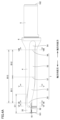
- FIG. 3 is a schematic left side view showing the configuration of the drill according to the present embodiment.
- FIG. 4A is a first schematic front view showing the configuration of the drill according to the present embodiment.
- FIG. 4B is a second schematic front view showing the configuration of the drill according to the present embodiment.
- FIG. 5 is a schematic cross-sectional view taken along line VV in FIG. 4A.
- FIG. 6 is a schematic cross-sectional view taken along line VI-VI in FIG. 4A.
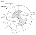
- FIG. 7 is a schematic cross-sectional view taken along line VII-VII in FIG. 4A.
- FIG. 8 is a schematic cross-sectional view taken along line VIII-VIII in FIG. 4A.
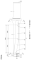
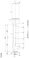
- FIG. 9A is a first schematic rear view showing the configuration of the drill according to the present embodiment.
- FIG. 9B is a second schematic rear view showing the configuration of the drill according to the present embodiment.
- FIG. 10 is a schematic cross-sectional view taken along line XX in FIG. 9A.
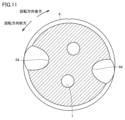
- FIG. 11 is a schematic cross-sectional view taken along line XI-XI in FIG. 9A.
- FIG. 12 is a virtual plane obtained by rotationally projecting each of the first cutting insert and the second cutting insert.
- FIG. 13 is a virtual plane obtained by rotationally projecting each of the first cutting insert and the second cutting insert.
- FIG. 14 is a diagram showing the amount of drill displacement for Samples 1 to 9.
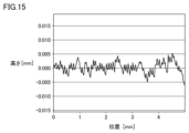
- FIG. 15 shows the wall height profile of the hole drilled using the Sample 4 drill.
- FIG. 16 shows the wall height profile of the hole drilled using sample 10.
- FIG. 17 is a schematic cross-sectional view showing the shapes of holes formed using the drills 100 of Samples 4, 11, and 12, respectively.
- An object of the present disclosure is to provide a drill that can improve chip discharge performance while suppressing a decrease in rigidity.
- the drill 100 is a drill 100 that rotates around a central axis A and includes a first cutting insert 10, a second cutting insert 20, and a main body 9.
- the first cutting insert 10 has a central blade 11.
- the second cutting insert 20 has a peripheral blade 21.
- the first cutting insert 10 and the second cutting insert 20 are attached to the main body 9.
- the main body 9 is provided with a first discharge groove 1 and a second discharge groove 2.
- the first discharge groove 1 discharges chips cut by the central blade 11.
- the second discharge groove 2 discharges chips cut by the peripheral blade 21.
- the start phase of the first discharge groove 1 is located in the range of +10° to +90° relative to the central blade 11
- the end phase of the first discharge groove 1 is located in the range of -40° to 0° relative to the central blade 11
- the start phase of the second discharge groove 2 is located in the range of +10° to +90° relative to the peripheral blade 21
- the end phase of the second discharge groove 2 is located in the range of -40° to 0° relative to the peripheral blade 21.
- the first discharge groove 1 has a first front groove portion 51 and a first rear groove portion 52 connected to the first front groove portion 51.
- the second discharge groove 2 has a second front groove portion 61 and a second rear groove portion 62 connected to the second front groove portion 61.
- the twist angle of the first front groove portion 51 monotonically decreases toward the first rear groove portion 52.
- the twist angle of the second front groove portion 61 monotonically decreases toward the second rear groove portion 62.
- the twist angle of each of the first rear groove portion 52 and the second rear groove portion 62 is 0°.
- the value obtained by dividing the amount of change in the twist angle of the first discharge groove 1 by the amount of change in the position in the direction along the central axis A is continuous.
- the value obtained by dividing the amount of change in the twist angle of the second discharge groove 2 by the amount of change in the position in the direction along the central axis A is continuous.
- the main body portion 9 is provided with a first pocket portion 32 that is continuous with the first discharge groove 1 and is located forward of the first cutting insert 10 in the rotational direction. In the direction along the central axis A, the distance from the front end of the first cutting insert 10 to the rear end of the first pocket portion 32 is 1.5 times or more the tool diameter.
- the length of each of the first discharge groove 1 and the second discharge groove 2 in the direction along the central axis A may be greater than or equal to 2 times and less than or equal to 8 times the tool diameter.
- the drill 100 when the length of the first front groove portion 51 in the direction along the central axis A is the first front length, the length of the first rear groove portion 52 is the first rear length, the length of the second front groove portion 61 is the second front length, and the length of the second rear groove portion 62 is the second rear length, the value obtained by dividing the first front length by the first rear length may be 0.3 or more and 3.0 or less, and the value obtained by dividing the second front length by the second rear length may be 0.3 or more and 3.0 or less.
- the drill 100 in a cross section perpendicular to the central axis A, if the cross-sectional area of the first front groove portion 51 is the first front area, the cross-sectional area of the first rear groove portion 52 is the first rear area, the cross-sectional area of the second front groove portion 61 is the second front area, and the cross-sectional area of the second rear groove portion 62 is the second rear area, the value obtained by dividing the first front area by the first rear area may be 1.01 or more and 1.02 or less, and the value obtained by dividing the second front area by the second rear area may be 1.01 or more and 1.02 or less.
- the cross-sectional area of the first discharge groove 1 may be larger than the cross-sectional area of the second discharge groove 2.
- the forward end position of the central cutting edge 11 is defined as the first position 71
- the intersection of the central axis A and the central cutting edge 11 is defined as the second position 72
- the intersection of a virtual line segment extending from the second position 72 in a direction perpendicular to the central axis A and the peripheral cutting edge 21 is defined as the third position 73.
- the distance from the central axis A to the first position 71 in the radial direction extending radially from the central axis A may be 30% to 40% of half the tool diameter, and the distance from the central axis A to the third position 73 in the radial direction may be 80% to 100% of half the tool diameter.
- the distance from the central axis A to the fourth position 74 in the radial direction may be greater than the distance from the fourth position 74 to the outermost end of the peripheral cutting edge 21 in the radial direction.
- the sine of the angle between a line perpendicular to the central axis A and a tangent to the central cutting edge 11 at the second position 72 in a virtual plane may be equal to or less than the tool diameter multiplied by 0.0070/mm.
- the unit of the angle is degrees, and the unit of the tool diameter is mm.
- the main body 9 may be provided with a second pocket portion 42 that is connected to the second discharge groove 2 and is located forward in the rotational direction relative to the second cutting insert 20.
- the rear end of the first pocket portion 32 may be located axially rearward of the rear end of the second pocket portion 42.
- FIG. 1 is a first perspective schematic diagram showing the configuration of a drill 100 according to this embodiment.
- FIG. 2 is a second perspective schematic diagram showing the configuration of the drill 100 according to this embodiment.
- the drill 100 according to this embodiment includes a first cutting insert 10, a second cutting insert 20, a body portion 9, a center cutting edge mounting screw 19, and an outer peripheral cutting edge mounting screw 29.
- the first cutting insert 10 has a center cutting edge 11.
- the second cutting insert 20 has an outer peripheral cutting edge 21.
- the first cutting insert 10 and the second cutting insert 20 are attached to the body portion 9.
- the first cutting insert 10 is attached to the body portion 9 using the center cutting edge mounting screw 19.
- the second cutting insert 20 is attached to the body portion 9 using the outer peripheral cutting edge mounting screw 29.
- the drill 100 can rotate around a central axis A.
- the main body 9 is provided with a first discharge groove 1 and a second discharge groove 2.
- the first discharge groove 1 discharges chips cut by the central blade 11.
- the second discharge groove 2 discharges chips cut by the peripheral blade 21.
- the main body portion 9 has a first body region 3, a second body region 6, and a shank 5.
- the front end surface 101 of the main body portion 9 is formed by the first body region 3.
- the front end surface 101 of the main body portion 9 is the portion facing the workpiece.
- the second body region 6 is connected to each of the first body region 3 and the shank 5.
- the second body region 6 is located between the first body region 3 and the shank 5.
- the rear end surface 102 of the main body portion 9 is located on the opposite side to the front end surface 101.
- the rear end surface 102 of the main body portion 9 is formed by the shank 5.
- the shank 5 is the portion that is attached to a device that rotates the drill 100.
- the direction parallel to the central axis A and from the rear end face 102 toward the front end face 101 is referred to as the axial forward direction.
- the direction parallel to the central axis A and from the front end face 101 toward the rear end face 102 is referred to as the axial rear direction.
- the direction extending radially from the central axis A is referred to as the radial direction.
- the first body region 3 has a first insert placement surface portion 31 and a first pocket portion 32.
- a first insert placement groove 33 is formed in the first insert placement surface portion 31.
- the first cutting insert 10 is placed in the first insert placement groove 33.
- the first pocket portion 32 is located forward of the first cutting insert 10 in the rotational direction.
- the first pocket portion 32 is connected to the first discharge groove 1. At least a portion of the first pocket portion 32 is located axially forward of the first discharge groove 1.
- the first pocket portion 32 is connected to the front end face 101.
- the first body region 3 is provided with a second insert placement surface portion 41 and a second pocket portion 42.
- a second insert placement groove 43 is formed in the second insert placement surface portion 41.
- the second cutting insert 20 is placed in the second insert placement groove 43.
- the second pocket portion 42 is located forward of the second cutting insert 20 in the rotational direction.
- the second pocket portion 42 is connected to the second discharge groove 2. At least a portion of the second pocket portion 42 is located axially forward of the second discharge groove 2.
- the second pocket portion 42 is connected to the front end face 101.
- the first main body region 3 has a first outer peripheral surface 4.
- Each of the first discharge groove 1 and the second discharge groove 2 is exposed to the outside at the first outer peripheral surface 4.
- Each of the first insert placement surface portion 31 and the first pocket portion 32 may be connected to the first outer peripheral surface 4.
- each of the second insert placement surface portion 41 and the second pocket portion 42 may be connected to the first outer peripheral surface 4.
- FIG. 3 is a schematic left side view showing the configuration of the drill 100 according to this embodiment.
- the first outer peripheral surface 4 when viewed in a direction along the central axis A, the first outer peripheral surface 4 is arc-shaped.
- the outer peripheral surface of the second body region 6 surrounds the first outer peripheral surface 4.
- the outer peripheral surface of the second body region 6 is substantially circular.
- Two coolant supply holes 7 may be formed in the main body portion 9. The two coolant supply holes 7 are exposed at the front end surface 101 of the main body portion 9.
- the first cutting insert 10 is disposed closer to the central axis A than the second cutting insert 20.
- the first cutting insert 10 may intersect with the central axis A. More specifically, when viewed in a direction along the central axis A, the central cutting edge 11 of the first cutting insert 10 may intersect with the central axis A.
- the second cutting insert 20 is disposed farther from the central axis A than the first cutting insert 10.
- the second cutting insert 20 is farther from the central axis A. More specifically, when viewed in a direction along the central axis A, the peripheral cutting edge 21 of the second cutting insert 20 does not intersect with the central axis A.
- a half line that connects the central axis A and the outermost end of the central blade 11 and extends radially from the central axis A is referred to as the thirteenth half line D13.
- the angle that the thirteenth half line D13 makes with the ridge line between the first pocket portion 32 and the front end face 101 is, for example, 45° or more and 120° or less.
- a half line that connects the central axis A and the outermost end of the peripheral blade 21 and extends radially from the central axis A is referred to as the 23rd half line D23.
- the angle that the 23rd half line D23 makes with the ridge line between the second pocket portion 42 and the front end face 101 is, for example, 45° or more and 120° or less.
- the first discharge groove 1 has a first front groove portion 51 and a first rear groove portion 52.
- the first rear groove portion 52 is continuous with the first front groove portion 51.
- the first rear groove portion 52 is located axially rearward of the first front groove portion 51.
- the twist angle ⁇ 3 of the first front groove portion 51 monotonically decreases toward the first rear groove portion 52.
- the twist angle ⁇ 3 of the first rear groove portion 52 is 0°. From another perspective, the first rear groove portion 52 extends along the central axis A.
- the value obtained by dividing the amount of change in the twist angle ⁇ 3 of the first discharge groove 1 by the amount of change in the position in the direction along the central axis A is continuous.
- the twist angle ⁇ 3 changes gradually. Specifically, in the region from the boundary (first boundary 57) between the first front groove portion 51 and the first rear groove portion 52 to a position axially forward by tool diameter x 1.0, the value obtained by dividing the amount of change in the twist angle ⁇ 3 of the first discharge groove 1 by the amount of change in the position in the direction along the central axis A (i.e. tool diameter x 1.0) is (2.0)°/mm or less.
- the length of the first front groove portion 51 is a first front length B11
- the length of the first rear groove portion 52 is a first rear length B12.
- the value obtained by dividing the first front length B11 by the first rear length B12 is, for example, 0.3 or more and 3.0 or less.
- the value obtained by dividing the first front length B11 by the first rear length B12 may be, for example, 0.5 or more and 2.0 or less, or 0.7 or more and 1.5 or less.
- FIG. 5 is a schematic cross-sectional view taken along line V-V in FIG. 4A.
- the cross-sectional view shown in FIG. 5 is perpendicular to the central axis A.
- the cross-sectional area of the first discharge groove 1 may be larger than the cross-sectional area of the second discharge groove 2.
- the cross-sectional area of the first discharge groove 1 is the area of the region surrounded by the surface of the main body 9 constituting the first discharge groove 1 and the first imaginary arc F1 along the first outer peripheral surface 4.
- the cross-sectional area of the second discharge groove 2 is the area of the region surrounded by the surface of the main body 9 constituting the second discharge groove 2 and the second imaginary arc F2 along the first outer peripheral surface 4.
- the radius of curvature of each of the first imaginary arc F1 and the second imaginary arc F2 is substantially the same as the radius of curvature of the first outer peripheral surface 4.
- FIG. 6 is a schematic cross-sectional view taken along line VI-VI in FIG. 4A.
- the cross-sectional view shown in FIG. 6 is perpendicular to the central axis A.
- the main body portion 9 is provided with a first front end groove portion 91 and a second front end groove portion 92.
- the first front end groove portion 91 is provided in the first insert placement surface portion 31.
- the second front end groove portion 92 is provided in the first pocket portion 32.
- the second front end groove portion 92 is spaced apart from the first front end groove portion 91.
- the first front end groove portion 91 and the second front end groove portion 92 are each located forward of the first front groove portion 51 in the axial direction.
- the first front end groove portion 91 and the second front end groove portion 92 are each connected to the first front groove portion 51.
- the position where the first front end groove portion 91 and the second front end groove portion 92 join together is considered to be the boundary between the first front end groove portion 91 and the second front end groove portion 92 and the first front groove portion 51.
- the boundary between the position where the first front end groove portion 91 and the second front end groove portion 92 join together and the first front groove portion 51 is considered to be the starting point position of the first discharge groove 1.
- FIG. 7 is a schematic cross-sectional view taken along line VII-VII in FIG. 4A.
- the cross-sectional view shown in FIG. 7 is perpendicular to the central axis A.
- the position in the axial direction of the cross-sectional view shown in FIG. 7 corresponds to the starting position of the first discharge groove 1 (first starting position 55).
- the eleventh half line D11 is a half line passing through the bottom of the first discharge groove 1 and the central axis A at the first starting position 55.
- the bottom of the first discharge groove 1 is the point on the first discharge groove 1 that is closest to the central axis A in a cross section perpendicular to the central axis A.
- the starting phase of the first discharge groove 1 corresponds to the phase of the eleventh half line D11.
- the phase of the central blade 11 corresponds to the phase of the thirteenth half line D13.
- the phase of the central blade 11 is set to 0°.
- the start phase (first start phase ⁇ 11) of the first discharge groove 1 is located in the range of +10° to +90° relative to the central blade 11 when viewed along the central axis A.
- the first start phase ⁇ 11 may be located in the range of +20° to +80° relative to the central blade 11, or may be located in the range of +30° to +70° relative to the central blade 11.
- the forward rotation is defined as a positive phase.
- the backward rotation is defined as a negative phase.
- the phase when the same phase is reached after N revolutions in the rotation direction is defined as N ⁇ 360° (where N is an integer).
- the phase when the same phase is reached after one revolution in the forward rotation direction is defined as +360°
- the phase when the same phase is reached after two revolutions in the rotation direction is defined as +720°.
- FIG. 8 is a schematic cross-sectional view taken along line VIII-VIII in FIG. 4A.
- the cross-sectional view shown in FIG. 8 is perpendicular to the central axis A.
- the axial position of the cross-sectional view shown in FIG. 8 corresponds to the end position (first end position 56) of the first discharge groove 1.
- the twelfth half line D12 is a half line that passes through the bottom of the first discharge groove 1 and the central axis A at the first end position 56.
- the end phase of the first discharge groove 1 corresponds to the phase of the twelfth half line D12.
- the end phase (first end phase ⁇ 12) of the first discharge groove 1 when viewed along the central axis A, is located in the range of -40° or more and 0° or less with respect to the central blade 11.
- the first end phase ⁇ 12 when viewed along the central axis A, may be located in the range of -30° or more and 0° or less with respect to the central blade 11, or may be located in the range of -20° or more and 0° or less with respect to the central blade 11.
- the first end position 56 may be the same as the end position (second end position 66) of the second discharge groove 2.
- the 22nd half line D22 is a half line that passes through the bottom of the second discharge groove 2 and the central axis A at the second end position 66.
- the bottom of the second discharge groove 2 is the point on the second discharge groove 2 that is closest to the central axis A in a cross section perpendicular to the central axis A.
- the end phase of the second discharge groove 2 corresponds to the phase of the 22nd half line D22.
- the 22nd half line D22 and the 12th half line D12 may be located on the same line.
- the phase of the 22nd half line D22 may be at a position rotated +180° relative to the 12th half line D12.
- the distance between the bottom of the second discharge groove 2 and the central axis A is greater than the distance between the bottom of the first discharge groove 1 and the central axis A.
- the cross-sectional area of the second discharge groove 2 is smaller than the cross-sectional area of the first discharge groove 1.
- the second discharge groove 2 has a second front groove portion 61 and a second rear groove portion 62.
- the second rear groove portion 62 is continuous with the second front groove portion 61.
- the second rear groove portion 62 is located axially rearward of the second front groove portion 61.
- the twist angle ⁇ 3 of the second front groove portion 61 monotonically decreases toward the second rear groove portion 62.
- the twist angle ⁇ 3 of the second rear groove portion 62 is 0°. From another perspective, the second rear groove portion 62 extends along the central axis A.
- the value obtained by dividing the amount of change in the twist angle ⁇ 3 of the second discharge groove 2 by the amount of change in the position in the direction along the central axis A is continuous.
- the twist angle ⁇ 3 changes gradually.
- the value obtained by dividing the amount of change in the twist angle ⁇ 3 of the second discharge groove 2 by the amount of change in the position in the direction along the central axis A is 2.0°°/mm or less.
- the length of the second front groove portion 61 is a second front length B21
- the length of the second rear groove portion 62 is a second rear length B22.
- the value obtained by dividing the second front length B21 by the second rear length B22 is, for example, 0.3 or more and 3.0 or less.
- the value obtained by dividing the second front length B21 by the second rear length B22 may be, for example, 0.5 or more and 2.0 or less, or 0.7 or more and 1.5 or less.
- FIG. 10 is a schematic cross-sectional view taken along line X-X in FIG. 9A.
- the cross-sectional view shown in FIG. 10 is perpendicular to the central axis A.
- the main body 9 is provided with a third front end groove 93 and a fourth front end groove 94.
- the third front end groove 93 is provided in the second insert placement surface 41.
- the fourth front end groove 94 is provided in the second pocket 42.
- the fourth front end groove 94 is spaced apart from the third front end groove 93.
- the third front end groove portion 93 and the fourth front end groove portion 94 are each located forward of the second discharge groove 2 in the axial direction.
- the third front end groove portion 93 and the fourth front end groove portion 94 are each connected to the second front groove portion 61.
- the position where the third front end groove portion 93 and the fourth front end groove portion 94 join together is set as the boundary between the third front end groove portion 93 and the fourth front end groove portion 94 and the second front groove portion 61.
- the boundary between the position where the third front end groove portion 93 and the fourth front end groove portion 94 join together and the second front groove portion 61 is set as the start position of the second discharge groove 2.
- the axial position of the cross-sectional view shown in FIG. 6 corresponds to the starting position of the second discharge groove 2 (second starting position 65).
- the 21st half line D21 is a half line that passes through the bottom of the second discharge groove 2 and the central axis A at the second starting position 65.
- the starting phase of the second discharge groove 2 corresponds to the phase of the 21st half line D21.
- the phase of the peripheral blade 21 corresponds to the phase of the 23rd half line D23.
- the phase of the peripheral blade 21 is set to 0°.
- the starting phase of the second discharge groove 2 (second starting phase ⁇ 21) is located in the range of +10° to +90° relative to the peripheral cutting edge 21.
- the second starting phase ⁇ 21 may be located in the range of +20° to +80° relative to the peripheral cutting edge 21, or in the range of +30° to +70° relative to the peripheral cutting edge 21.
- the end phase of the second discharge groove 2 (second end phase ⁇ 22) is located in the range of -40° to 0° relative to the peripheral cutting edge 21.
- the second end phase ⁇ 22 may be located in the range of -30° to 0° relative to the peripheral cutting edge 21, or in the range of -20° to 0° relative to the peripheral cutting edge 21.
- FIG. 11 is a schematic cross-sectional view taken along line XI-XI in FIG. 9A.
- the cross-sectional view shown in FIG. 11 is perpendicular to the central axis A.
- the main body portion 9 is provided with a first rear end groove portion 54 and a second rear end groove portion 64. More specifically, as shown in FIG. 9A, each of the first rear end groove portion 54 and the second rear end groove portion 64 is provided in the second body region 6.
- the diameter of the second body region 6 is larger than the diameter of the first body region 3.
- the second body region 6 has a portion whose diameter increases axially rearward.
- the first rear end groove portion 54 is connected to the first rear groove portion 52.
- the first rear end groove portion 54 is located axially rearward of the first rear groove portion 52.
- the cross-sectional area of the first rear end groove portion 54 is smaller than the cross-sectional area of the first rear groove portion 52.
- the cross-sectional area of the first rear end groove portion 54 in a cross section perpendicular to the central axis A decreases toward the axial rear.
- the second rear end groove portion 64 is connected to the second rear groove portion 62.
- the second rear end groove portion 64 is located axially rearward of the second rear groove portion 62.
- the cross-sectional area of the second rear end groove portion 64 is smaller than the cross-sectional area of the second rear groove portion 62.
- the cross-sectional area of the second rear end groove portion 64 in a cross section perpendicular to the central axis A decreases toward the axial rear.
- the first front area may be larger than the first rear area.
- the value obtained by dividing the first front area by the first rear area may be 1.01 or more and 1.02 or less.
- the value obtained by dividing the first front area by the first rear area may be 1.012 or more and 1.018 or less, or 1.014 or more and 1.016 or less.
- the second front area may be larger than the second rear area.
- the value obtained by dividing the second front area by the second rear area may be 1.01 or more and 1.02 or less.
- the value obtained by dividing the second front area by the second rear area may be 1.012 or more and 1.018 or less, or 1.014 or more and 1.016 or less.
- FIGS. 12 and 13 are imaginary planes obtained by rotating and projecting each of the first cutting insert 10 and the second cutting insert 20 around the central axis A.
- the imaginary plane 150 includes the central axis A.
- the front end position of the central cutting edge 11 is defined as the first position 71.
- the first position 71 is located most forward in the axial direction.
- the intersection of the central axis A and the central cutting edge 11 is defined as the second position 72.
- the intersection of an imaginary line segment extending from the second position 72 in a direction perpendicular to the central axis A and the peripheral blade 21 is set to the third position 73.
- the tool radius is the distance from the central axis A in the radial direction to the outermost end of the peripheral blade 21.
- the outermost end of the peripheral blade 21 is set to the fifth position 75.
- the tool diameter E is twice the distance from the central axis A to the fifth position 75 in the radial direction.
- the radial direction is the direction extending radially from the central axis A.
- the radial direction is perpendicular to the central axis A.
- the distance from the central axis A to the first position 71 in the radial direction is 30% or more and 40% or less of the tool radius.
- the distance from the central axis A to the first position 71 in the radial direction may be 23% or more and 37% or less of the tool radius, or may be 26% or more and 34% or less of the tool radius.
- the distance from the central axis A to the third position 73 in the radial direction is 80% or more and 100% or less of the tool radius.
- the distance from the central axis A to the third position 73 in the radial direction may be 84% or more and 96% or less of the tool radius, or may be 88% or more and 92% or less of the tool radius.
- the intersection of the central blade 11 and the peripheral blade 21 is the fourth position 74.
- the distance from the central axis A to the fourth position 74 in the radial direction may be greater than the distance from the fourth position 74 to the fifth position 75 in the radial direction.
- the distance from the central axis A to the fourth position 74 in the radial direction corresponds to the effective length of the central blade 11 in the radial direction.
- the distance from the fourth position 74 to the fifth position 75 in the radial direction corresponds to the effective length of the peripheral blade 21 in the radial direction.
- the distance from the central axis A to the fourth position 74 in the radial direction may be 1.05 times or more, or 1.1 times or more, of the distance from the fourth position 74 in the radial direction to the fifth position 75 of the peripheral cutting edge 21.
- the distance from the central axis A to the fourth position 74 in the radial direction may be 2 times or less, or 1.8 times or less, of the distance from the fourth position 74 to the fifth position 75 in the radial direction.
- the length of the first discharge groove 1 in the direction along the central axis A is a first total length B13.
- the first total length B13 may be greater than or equal to two times and less than or equal to eight times the tool diameter.
- the first total length B13 is the sum of the length of the first front groove portion 51 and the length of the first rear groove portion 52. In the direction along the central axis A, the first total length B13 may be greater than or equal to two times and less than or equal to seven times the tool diameter.
- the distance from the front end of the first cutting insert 10 to the rear end of the first pocket portion 32 in the direction along the central axis A is defined as a first pocket length C1.
- the first pocket length C1 is 1.5 times or more the tool diameter.
- the front end of the first cutting insert 10 corresponds to the front end position of the central cutting edge 11.
- the rear end of the first pocket portion 32 is the boundary between the surface of the first pocket portion 32, the first outer peripheral surface 4 of the first body region 3, and the surface of the first front groove portion 51.
- the first pocket length C1 may be 1.8 times or more the tool diameter, or may be 2 times or more the tool diameter. In the direction along the central axis A, the first pocket length C1 may be 3 times or less the tool diameter, or may be 2.5 times or less the tool diameter.
- the length of the second discharge groove 2 in the direction along the central axis A is a second total length B23.
- the second total length B23 may be greater than or equal to two times and less than or equal to eight times the tool diameter.
- the second total length B23 is the sum of the length of the second front groove portion 61 and the length of the second rear groove portion 62. In the direction along the central axis A, the second total length B23 may be greater than or equal to two times and less than or equal to seven times the tool diameter.
- the distance from the front end of the second cutting insert 20 to the rear end of the second pocket portion 42 in the direction along the central axis A is the second pocket length C2.
- the second pocket length C2 may be smaller than the first pocket length C1.
- the front end of the second cutting insert 20 corresponds to the front-most position of the peripheral cutting edge 21.
- the rear end of the second pocket portion 42 is the boundary between the surface of the second pocket portion 42, the first outer peripheral surface 4 of the first body region 3, and the surface of the fourth front end groove portion 94.
- the rear end of the first pocket portion 32 may be located axially rearward of the rear end of the second pocket portion 42.
- the line perpendicular to the central axis A is the third line D3.
- the tangent to the central blade 11 at the second position 72 is the fourth line D4.
- the third line D3 passes through the second position 72.
- the angle between the third line D3 and the fourth line D4 is the fourth angle ⁇ 4.
- the fourth angle ⁇ 4 may be 8° or less, 6° or less, or 4° or less.
- the fourth angle ⁇ 4 may be 1° or more, or 2° or more.
- the sine of the fourth angle ⁇ 4 i.e., sin ⁇ 4) may be less than or equal to the value obtained by multiplying the tool diameter by 0.0070/mm.
- the sine of the fourth angle ⁇ 4 may be less than or equal to the value obtained by multiplying the tool diameter by 0.0060/mm, or may be less than or equal to the value obtained by multiplying the tool diameter by 0.0050/mm.
- the sine of the fourth angle ⁇ 4 may be equal to or greater than the tool diameter multiplied by 0.0010/mm, or may be equal to or greater than the tool diameter multiplied by 0.0020/mm.
- the unit of the fourth angle ⁇ 4 is degrees.
- the unit of the tool diameter is mm.
- the main body 9 is provided with a first discharge groove 1 and a second discharge groove 2.
- the first discharge groove 1 discharges chips cut by the central blade 11.
- the second discharge groove 2 discharges chips cut by the peripheral blade 21.
- the start phase of the first discharge groove 1 is located in a range of +10° to +90° relative to the central blade 11
- the end phase of the first discharge groove 1 is located in a range of -40° to 0° relative to the central blade 11
- the start phase of the second discharge groove 2 is located in a range of +10° to +90° relative to the peripheral blade 21
- the end phase of the second discharge groove 2 is located in a range of -40° to 0° relative to the peripheral blade 21.
- the first discharge groove 1 has a first front groove portion 51 and a first rear groove portion 52 connected to the first front groove portion 51.
- the second discharge groove 2 has a second front groove portion 61 and a second rear groove portion 62 connected to the second front groove portion 61.
- the twist angle ⁇ 3 of the first front groove portion 51 monotonically decreases toward the first rear groove portion 52.
- the twist angle ⁇ 3 of the second front groove portion 61 monotonically decreases toward the second rear groove portion 62.
- the twist angle ⁇ 3 of each of the first rear groove portion 52 and the second rear groove portion 62 is 0°. This makes it possible to improve the dischargeability of chips while suppressing a decrease in the rigidity of the main body portion 9. As a result, it is possible to improve the quality of the hole formed in the workpiece.
- the value obtained by dividing the amount of change in the twist angle ⁇ 3 of the first discharge groove 1 by the amount of change in the position in the direction along the central axis A is continuous.
- the value obtained by dividing the amount of change in the twist angle ⁇ 3 of the second discharge groove 2 by the amount of change in the position in the direction along the central axis A is continuous.
- the central blade 11 Since the central blade 11 is located radially closer to the central axis A than the peripheral blade 21, the cutting speed of the central blade 11 is lower than the cutting speed of the peripheral blade 21. Therefore, chips cut by the central blade 11 are more difficult to discharge than chips cut by the peripheral blade 21. In other words, the chip discharge ability of the first discharge groove 1 is lower than the chip discharge ability of the second discharge groove 2.
- the main body 9 is provided with a first pocket portion 32 that is connected to the first discharge groove 1 and is located forward of the first cutting insert 10 in the direction of rotation.
- the distance from the front end of the first cutting insert 10 to the rear end of the first pocket portion 32 is 1.5 times the tool diameter or more.
- the chips cut by the central cutting edge 11 in the first pocket curl By making the distance from the front end of the first cutting insert 10 to the rear end of the first pocket portion 32 1.5 times the tool diameter or more, sufficient space can be secured for the chips to curl. This improves the dischargeability of the chips cut by the central cutting edge 11.
- the length of each of the first discharge groove 1 and the second discharge groove 2 in the direction along the central axis A may be from 2 to 8 times the tool diameter. This makes it possible to form a deep hole in the workpiece.
- the drill 100 if the length of the first front groove portion 51 in the direction along the central axis A is the first front length B11, the length of the first rear groove portion 52 is the first rear length B12, the length of the second front groove portion 61 is the second front length B21, and the length of the second rear groove portion 62 is the second rear length B22, the value obtained by dividing the first front length B11 by the first rear length B12 may be 0.3 or more and 3.0 or less, and the value obtained by dividing the second front length B21 by the second rear length B22 may be 0.3 or more and 3.0 or less. This makes it possible to improve the dischargeability of chips while suppressing a decrease in rigidity.
- the effect of the first front groove portion 51 on chip dischargeability is greater than the effect of the first rear groove portion 52 on chip dischargeability.
- the effect of the second front groove portion 61 on chip dischargeability is greater than the effect of the second rear groove portion 62 on chip dischargeability.
- the drill 100 in a cross section perpendicular to the central axis A, if the cross-sectional area of the first front groove portion 51 is the first front area, the cross-sectional area of the first rear groove portion 52 is the first rear area, the cross-sectional area of the second front groove portion 61 is the second front area, and the cross-sectional area of the second rear groove portion 62 is the second rear area, the value obtained by dividing the first front area by the first rear area may be 1.01 or more and 1.02 or less, and the value obtained by dividing the second front area by the second rear area may be 1.01 or more and 1.02 or less. This makes it possible to further improve the dischargeability of chips while suppressing a decrease in rigidity.
- the cross-sectional area of the first discharge groove 1 may be larger than the cross-sectional area of the second discharge groove 2 in a cross section perpendicular to the central axis A. This makes it possible to improve the chip discharge performance of the first discharge groove 1 while suppressing a decrease in rigidity.
- the front end position of the central cutting edge 11 is the first position 71
- the intersection of the central axis A and the central cutting edge 11 is the second position 72
- the intersection of a virtual line segment extending from the second position 72 in a direction perpendicular to the central axis A and the peripheral cutting edge 21 is the third position 73.
- the distance from the central axis A to the first position 71 in the radial direction extending radially from the central axis A is 30% to 40% of half the tool diameter
- the distance from the central axis A to the third position 73 in the radial direction may be 80% to 100% of half the tool diameter.
- the radial distance from the central axis A to the fourth position 74 may be greater than the radial distance from the fourth position 74 to the outermost edge of the peripheral cutting edge 21. This balances the cutting force of the peripheral cutting edge 21 and the cutting force of the central cutting edge 11 during cutting. This reduces the variation in the diameter of the hole formed in the workpiece.
- the amount of hole diameter displacement corresponding to the hole diameter enlargement allowance is proportional to (sin ⁇ )/(tool diameter).
- the proportionality constant here is a value determined by the holder material, etc., and is between 2 mm 2 and 200 mm 2.
- ⁇ is the angle between a line perpendicular to the central axis A and a tangent to the central cutting edge 11.
- the smaller the tool diameter the larger the hole diameter enlargement allowance at the hole entrance tends to be.
- the hole diameter enlargement allowance can be reduced by reducing the angle between a line perpendicular to the central axis A and a tangent to the central cutting edge 11.
- the amount of hole diameter displacement ( ⁇ ) can be calculated using the following formula 1.
- Fsin ⁇ is the cutting resistance.
- ⁇ is the central cutting edge angle.
- L is the projection length.
- E is Young's modulus.
- E depends on the material.
- I is the second moment of area. I is calculated as (constant) ⁇ (tool diameter) 4. I depends on the cross-sectional shape.
- the amount of hole diameter displacement ( ⁇ s ) when the tool diameter is a reference diameter (e.g., 20.0 mm) can be calculated using the following formula 2.
- the tool diameter is D S.
- the extension length is L S.
- the ratio of the extension length to the tool diameter is, for example, 5.
- the central blade angle is ⁇ S.
- the cutting resistance is F sin ⁇ S.
- the Young's modulus is E.
- the second moment of area is I S. I S is calculated as (constant) ⁇ (tool diameter) 4. In other words, I S is (constant) ⁇ (D S ) 4 .
- the amount of hole diameter displacement ( ⁇ d ) when the tool diameter is the developed diameter (e.g., 25.0 mm, 15.0 mm, etc.) can be calculated by the following formula 3.
- the tool diameter is D d .
- the extension length is L d .
- L d /D d is equal to L s /D s .
- the central cutting edge angle is ⁇ d .
- the cutting resistance is F sin ⁇ d .
- the Young's modulus is E .
- the second moment of area is I d . I d is calculated as (constant) ⁇ (tool diameter) 4 .
- I d is (constant) ⁇ (D d ) 4 . That is, I d is (D d ) 4 / (D s ) 4 ⁇ I s .
- the amount of displacement of the holder is proportional to (sin ⁇ )/(tool diameter), where C is a proportionality constant. Therefore, by measuring the amount of displacement of the holder, which is the reference diameter, the amount of displacement of different tool diameters (developed diameters) can be calculated.
- the sine of the angle between a line perpendicular to the central axis A and a tangent to the central cutting edge 11 at the second position 72 on the imaginary plane 150 may be equal to or less than the tool diameter multiplied by 0.0070/mm. This reduces the vibration of the drill 100 when it bites into the workpiece. Therefore, even if the tool diameter is small, the hole diameter enlargement allowance can be reduced.
- the main body 9 may be provided with a second pocket portion 42 that is connected to the second discharge groove 2 and is located forward in the rotational direction of the second cutting insert 20.
- the rear end of the first pocket portion 32 may be located axially rearward of the rear end of the second pocket portion 42. While chips cut by the peripheral cutting edge 21 need to curl with a small curvature, it is desirable for chips cut by the central cutting edge 11 to curl with a large curvature. By adjusting the pocket width to suit each chip, chip processing can be stabilized.
- Example 1 (Sample preparation) First, the drills 100 of Samples 1 to 9 were prepared.
- the drills 100 of Samples 3 to 8 are examples.
- each of the first end point phase and the second end point phase was set to be equal to or greater than -40° and equal to or less than 0°.
- the drills 100 of Samples 1 to 9 are comparative examples. In the comparative examples, each of the first end point phase and the second end point phase was set to be an angle smaller than -40° or an angle larger than 0°.
- the first end point phase and the second end point phase in each sample are as shown in Table 1.
- the first start phase and the second start phase were each set to 45°.
- the cross-sectional area of the second front groove portion 61 was made smaller than the cross-sectional area of the first front groove portion 51.
- the cross-sectional area of the second rear groove portion 62 was made smaller than the cross-sectional area of the first rear groove portion 52.
- the cross-sectional area of the first front groove portion 51 was made larger than the cross-sectional area of the first rear groove portion 52.
- the cross-sectional area of the second front groove portion 61 was made larger than the cross-sectional area of the second rear groove portion 62.
- the length of the first pocket portion 32 was set to 1.58 times the tool diameter.
- the cutting edge length of the central blade 11 was set to 6.7 mm.
- the length of the first front groove portion 51 was set to 49 mm.
- the length of the first rear groove portion 52 was set to 45 mm.
- the length of the second pocket portion 42 was set to 0.91 times the tool diameter.
- the cutting edge length of the peripheral blade 21 was set to 6.23 mm.
- the length of the second front groove portion 61 was set to 49 mm.
- the length of the second rear groove portion 62 was set to 45 mm.
- Fig. 14 is a diagram showing the displacement amount of the drill 100 of samples 1 to 9. As shown in Fig. 14, when each of the first end point phase and the second end point phase was -40° or more and 15° or less, the displacement amount was small. On the other hand, when each of the first end point phase and the second end point phase was greater than 0°, it was difficult to discharge the chips.
- Example 2 (Sample preparation) Next, the drills 100 of Samples 4 and 10 were prepared.
- the drill 100 of Sample 4 is an example.
- the first pocket length C1 (the length of the pocket portion on the central cutting edge side) was set to 1.5 times or more the tool diameter. Specifically, the first pocket length C1 was set to 1.58 times the tool diameter.
- the drill 100 of Sample 10 is a comparative example. In the comparative example, the first pocket length C1 was set to less than 1.5 times the tool diameter. Specifically, the first pocket length C1 was set to 1.01 times the tool diameter.
- the first start phase and the second start phase were each set to 45°.
- the first end phase and the second end phase were each set to -5°.
- the second pocket length C2 (the length of the pocket portion on the peripheral cutting edge side) was set to 0.91 times the tool diameter.
- the cutting edge length of the central cutting edge 11 was set to 6.7 mm.
- the length of the first front groove portion 51 was set to 49 mm.
- the length of the first rear groove portion 52 was set to 45 mm.
- the cutting edge length of the peripheral cutting edge 21 was set to 6.23 mm.
- the length of the second front groove portion 61 was set to 49 mm.
- the length of the second rear groove portion 62 was set to 45 mm.
- the drills 100 of samples 4 and 10 were used to drill holes in the workpiece.
- a vertical machining center NVX5080 manufactured by DGM Mori Seiki Co., Ltd. was used.
- the workpiece was JIS G 4051 S50C.
- the peripheral speed Vc was 150 m/min.
- the feed rate f was 0.08 mm/revolution.
- Coolant was supplied from inside the drill 100.
- the oil supply pressure was 2 MPa.
- the wall height profile was measured on the surface of the hole formed in the workpiece.
- Fig. 15 is a diagram showing the height profile of the wall surface of a hole formed using the drill 100 of sample 4.
- the horizontal axis of Fig. 15 is the position in the depth direction of the hole.
- the horizontal axis of Fig. 15 is the height of the wall surface of the hole.
- the arithmetic mean roughness Ra of the hole wall surface was 1.496 ⁇ m.
- the root mean square roughness Rq of the hole wall surface was 1.858 ⁇ m.
- the maximum height roughness Rz of the hole wall surface was 9.477 ⁇ m.
- Figure 16 is a diagram showing the height profile of the wall surface of a hole formed using the drill 100 of sample 10.
- the horizontal axis of Figure 16 is the position in the depth direction of the hole.
- the horizontal axis of Figure 16 is the height of the wall surface of the hole.
- the arithmetic mean roughness Ra of the hole wall surface was 2.259 ⁇ m.
- the root mean square roughness Rq of the hole wall surface was 2.885 ⁇ m.
- the maximum height roughness Rz of the hole wall surface was 13.18 ⁇ m.
- Example 3 (Sample preparation) Next, the drills 100 of samples 4, 11, and 12 were prepared.
- the drills 100 of samples 4 and 12 are examples.
- the tool diameter was 20 mm, and the angle between the central cutting edge 11 and a line perpendicular to the central axis A was 8°.
- the tool diameter was 18.5 mm, and the angle ⁇ between the central cutting edge 11 and a line perpendicular to the central axis A was 4°.
- the sine (i.e., sin ⁇ ) of the angle ⁇ between the central cutting edge 11 and a line perpendicular to the central axis A is equal to or less than the tool diameter (mm) multiplied by 0.0070/mm.
- the drill 100 of sample 11 is a comparative example.
- the tool diameter is 18.5 mm
- the angle between the central cutting edge 11 and a line perpendicular to the central axis A is 8°.
- the sine of the angle ⁇ i.e., sin ⁇
- the tool diameter (mm) multiplied by 0.0070/mm is greater than the tool diameter (mm) multiplied by 0.0070/mm.
- the first start phase and the second start phase were each set to 45°.
- the first end phase and the second end phase were each set to -5°.
- the second pocket length C2 (the length of the pocket portion on the peripheral cutting edge side) was set to 0.91 times the tool diameter.
- the length of the first pocket portion 32 was set to 1.58 times the tool diameter.
- the drills 100 of Samples 4, 11, and 12 were used to drill holes in the workpiece 80.
- the vertical machining center used was NVX5080 manufactured by DGM Mori Seiki Co., Ltd.
- the workpiece was JIS G 4051 S50C.
- the peripheral speed Vc was 150 m/min.
- the feed rate f was 0.06 mm/revolution. Coolant was supplied from inside the drill 100.
- the oil supply pressure was 2 MPa.
- (Evaluation Results) 17 is a schematic cross-sectional view showing the shape of a hole formed using each of the drills 100 of samples 4, 11, and 12. As shown in FIG. 17, the diameter of the hole is enlarged at the entrance of the hole formed in the workpiece 80.
- the hole diameter at the back is a first diameter W1.
- the first diameter W1 is substantially the same as the tool diameter.
- the hole diameter at the entrance is a third diameter W3.
- the third diameter W3 is larger than the first diameter W1.
- the first diameter W1 at the depth of the hole formed using each of the drills 100 of samples 4, 11, and 12 was 20.1 mm, 18.8 mm, and 18.8 mm, respectively.
- the third diameter W3 at the entrance of the hole formed using each of the drills 100 of samples 4, 11, and 12 was 20.2 mm, 20.0 mm, and 18.8 mm, respectively.
- the cutting resistance at the entrance of the hole formed using each of the drills 100 of samples 4, 11, and 12 was 550 N, 750 N, and 500 N, respectively.
Landscapes
- Engineering & Computer Science (AREA)
- Mechanical Engineering (AREA)
- Drilling Tools (AREA)
Priority Applications (3)
| Application Number | Priority Date | Filing Date | Title |
|---|---|---|---|
| CN202480044627.9A CN121464008A (zh) | 2023-07-06 | 2024-06-14 | 钻头 |
| JP2024566001A JP7616557B1 (ja) | 2023-07-06 | 2024-06-14 | ドリル |
| US19/107,102 US20260061501A1 (en) | 2023-07-06 | 2024-06-14 | Drill |
Applications Claiming Priority (2)
| Application Number | Priority Date | Filing Date | Title |
|---|---|---|---|
| JPPCT/JP2023/025141 | 2023-07-06 | ||
| JP2023025141 | 2023-07-06 |
Publications (1)
| Publication Number | Publication Date |
|---|---|
| WO2025009363A1 true WO2025009363A1 (ja) | 2025-01-09 |
Family
ID=94172070
Family Applications (1)
| Application Number | Title | Priority Date | Filing Date |
|---|---|---|---|
| PCT/JP2024/021696 Ceased WO2025009363A1 (ja) | 2023-07-06 | 2024-06-14 | ドリル |
Country Status (4)
| Country | Link |
|---|---|
| US (1) | US20260061501A1 (https=) |
| JP (1) | JP7616557B1 (https=) |
| CN (1) | CN121464008A (https=) |
| WO (1) | WO2025009363A1 (https=) |
Citations (8)
| Publication number | Priority date | Publication date | Assignee | Title |
|---|---|---|---|---|
| JP2006205285A (ja) * | 2005-01-26 | 2006-08-10 | Tungaloy Corp | スローアウェイ式ドリル |
| US20080170921A1 (en) * | 2007-01-17 | 2008-07-17 | Sandvik Intellectual Property Ab | Rotatable multi-operation tool for chip removing machining, and a basic body therefor |
| JP2009262319A (ja) * | 2008-03-31 | 2009-11-12 | Mitsubishi Materials Corp | ドリル用インサートおよびインサートドリル |
| JP2010264531A (ja) * | 2009-05-13 | 2010-11-25 | Mitsubishi Materials Corp | 刃先交換式ドリル |
| JP2012206216A (ja) * | 2011-03-30 | 2012-10-25 | Mitsubishi Materials Corp | ドリルホルダ及び刃先交換式ドリル |
| WO2013018764A1 (ja) | 2011-07-29 | 2013-02-07 | 京セラ株式会社 | 切削工具用ホルダおよび切削工具ならびにそれを用いた被削材の切削方法 |
| JP2013027962A (ja) * | 2011-07-29 | 2013-02-07 | Kyocera Corp | 切削工具用ホルダおよび切削工具ならびにそれを用いた被削材の切削方法 |
| JP2021100772A (ja) * | 2019-12-24 | 2021-07-08 | 京セラ株式会社 | 回転工具及び切削加工物の製造方法 |
-
2024
- 2024-06-14 JP JP2024566001A patent/JP7616557B1/ja active Active
- 2024-06-14 CN CN202480044627.9A patent/CN121464008A/zh active Pending
- 2024-06-14 US US19/107,102 patent/US20260061501A1/en active Pending
- 2024-06-14 WO PCT/JP2024/021696 patent/WO2025009363A1/ja not_active Ceased
Patent Citations (8)
| Publication number | Priority date | Publication date | Assignee | Title |
|---|---|---|---|---|
| JP2006205285A (ja) * | 2005-01-26 | 2006-08-10 | Tungaloy Corp | スローアウェイ式ドリル |
| US20080170921A1 (en) * | 2007-01-17 | 2008-07-17 | Sandvik Intellectual Property Ab | Rotatable multi-operation tool for chip removing machining, and a basic body therefor |
| JP2009262319A (ja) * | 2008-03-31 | 2009-11-12 | Mitsubishi Materials Corp | ドリル用インサートおよびインサートドリル |
| JP2010264531A (ja) * | 2009-05-13 | 2010-11-25 | Mitsubishi Materials Corp | 刃先交換式ドリル |
| JP2012206216A (ja) * | 2011-03-30 | 2012-10-25 | Mitsubishi Materials Corp | ドリルホルダ及び刃先交換式ドリル |
| WO2013018764A1 (ja) | 2011-07-29 | 2013-02-07 | 京セラ株式会社 | 切削工具用ホルダおよび切削工具ならびにそれを用いた被削材の切削方法 |
| JP2013027962A (ja) * | 2011-07-29 | 2013-02-07 | Kyocera Corp | 切削工具用ホルダおよび切削工具ならびにそれを用いた被削材の切削方法 |
| JP2021100772A (ja) * | 2019-12-24 | 2021-07-08 | 京セラ株式会社 | 回転工具及び切削加工物の製造方法 |
Also Published As
| Publication number | Publication date |
|---|---|
| JP7616557B1 (ja) | 2025-01-17 |
| CN121464008A (zh) | 2026-02-03 |
| US20260061501A1 (en) | 2026-03-05 |
| JPWO2025009363A1 (https=) | 2025-01-09 |
Similar Documents
| Publication | Publication Date | Title |
|---|---|---|
| JP4976181B2 (ja) | スローアウェイドリルのチップ配置方法 | |
| JP6086174B2 (ja) | ドリル | |
| US20100061821A1 (en) | Insert for Drill, Drill and Method of Cutting Work Material | |
| WO2023243004A1 (ja) | ドリル | |
| WO2009142323A1 (ja) | ドリルおよび切削インサート並びに被削加工物の製造方法 | |
| CN101432090A (zh) | 旋转切削工具 | |
| WO2011132686A1 (ja) | ガンドリル | |
| WO2022215114A1 (ja) | 切削工具 | |
| JP6977228B1 (ja) | 回転切削工具用切削インサートおよび回転切削工具 | |
| JP7386339B2 (ja) | ドリル及び切削加工物の製造方法 | |
| JP7616557B1 (ja) | ドリル | |
| JPH10291115A (ja) | スローアウェイエンドミル | |
| JP7763258B2 (ja) | ドリル | |
| WO2019220778A9 (ja) | ドリル用切削インサートおよびドリル | |
| JP7164084B2 (ja) | ドリル | |
| JPWO2023032180A5 (https=) | ||
| JPH0524218U (ja) | 穴明け工具 | |
| JP4954044B2 (ja) | ドリル | |
| JP7456565B1 (ja) | ドリル | |
| WO2025187314A1 (ja) | ドリル | |
| WO2025105294A1 (ja) | ドリル | |
| WO2025105312A1 (ja) | ドリル | |
| WO2025187304A1 (ja) | ドリル | |
| KR20250168415A (ko) | 드릴 및 절삭 가공물의 제조 방법 | |
| JP2009101452A (ja) | ドリル |
Legal Events
| Date | Code | Title | Description |
|---|---|---|---|
| WWE | Wipo information: entry into national phase |
Ref document number: 2024566001 Country of ref document: JP |
|
| 121 | Ep: the epo has been informed by wipo that ep was designated in this application |
Ref document number: 24835878 Country of ref document: EP Kind code of ref document: A1 |
|
| WWE | Wipo information: entry into national phase |
Ref document number: 202647000084 Country of ref document: IN |
|
| WWP | Wipo information: published in national office |
Ref document number: 202647000084 Country of ref document: IN |
|
| WWE | Wipo information: entry into national phase |
Ref document number: 2024835878 Country of ref document: EP |
|
| NENP | Non-entry into the national phase |
Ref country code: DE |
|
| ENP | Entry into the national phase |
Ref document number: 2024835878 Country of ref document: EP Effective date: 20260206 |