WO2025009231A1 - サイドシール及びリニアガイド - Google Patents
サイドシール及びリニアガイド Download PDFInfo
- Publication number
- WO2025009231A1 WO2025009231A1 PCT/JP2024/010346 JP2024010346W WO2025009231A1 WO 2025009231 A1 WO2025009231 A1 WO 2025009231A1 JP 2024010346 W JP2024010346 W JP 2024010346W WO 2025009231 A1 WO2025009231 A1 WO 2025009231A1
- Authority
- WO
- WIPO (PCT)
- Prior art keywords
- fitting
- holding member
- slider
- side seal
- guide rail
- Prior art date
- Legal status (The legal status is an assumption and is not a legal conclusion. Google has not performed a legal analysis and makes no representation as to the accuracy of the status listed.)
- Ceased
Links
Images













Classifications
-
- F—MECHANICAL ENGINEERING; LIGHTING; HEATING; WEAPONS; BLASTING
- F16—ENGINEERING ELEMENTS AND UNITS; GENERAL MEASURES FOR PRODUCING AND MAINTAINING EFFECTIVE FUNCTIONING OF MACHINES OR INSTALLATIONS; THERMAL INSULATION IN GENERAL
- F16C—SHAFTS; FLEXIBLE SHAFTS; ELEMENTS OR CRANKSHAFT MECHANISMS; ROTARY BODIES OTHER THAN GEARING ELEMENTS; BEARINGS
- F16C29/00—Bearings for parts moving only linearly
- F16C29/04—Ball or roller bearings
- F16C29/06—Ball or roller bearings in which the rolling bodies circulate partly without carrying load
-
- F—MECHANICAL ENGINEERING; LIGHTING; HEATING; WEAPONS; BLASTING
- F16—ENGINEERING ELEMENTS AND UNITS; GENERAL MEASURES FOR PRODUCING AND MAINTAINING EFFECTIVE FUNCTIONING OF MACHINES OR INSTALLATIONS; THERMAL INSULATION IN GENERAL
- F16C—SHAFTS; FLEXIBLE SHAFTS; ELEMENTS OR CRANKSHAFT MECHANISMS; ROTARY BODIES OTHER THAN GEARING ELEMENTS; BEARINGS
- F16C29/00—Bearings for parts moving only linearly
- F16C29/08—Arrangements for covering or protecting the ways
-
- F—MECHANICAL ENGINEERING; LIGHTING; HEATING; WEAPONS; BLASTING
- F16—ENGINEERING ELEMENTS AND UNITS; GENERAL MEASURES FOR PRODUCING AND MAINTAINING EFFECTIVE FUNCTIONING OF MACHINES OR INSTALLATIONS; THERMAL INSULATION IN GENERAL
- F16C—SHAFTS; FLEXIBLE SHAFTS; ELEMENTS OR CRANKSHAFT MECHANISMS; ROTARY BODIES OTHER THAN GEARING ELEMENTS; BEARINGS
- F16C33/00—Parts of bearings; Special methods for making bearings or parts thereof
- F16C33/72—Sealings
- F16C33/76—Sealings of ball or roller bearings
Definitions
- the present invention relates to a side seal and a linear guide.
- a linear guide comprises a guide rail extending in the axial direction and a slider mounted on the guide rail so as to be movable relative to the guide rail.
- the slider moves relative to the guide rail in the axial direction via a number of rolling elements (balls) that circulate between rolling element rolling grooves formed in the guide rail and the slider.
- rolling elements balls
- the slider also has side seals attached to both end faces in the direction in which the guide rail extends, sealing the gap between the guide rail and the slider and preventing foreign matter such as dirt, dust, and dirt from entering the inside of the slider.
- Patent Document 1 describes a linear guide device in which a sliding scraper having a groove that slides against the guide rail is fitted into a U-shaped groove in a mounting plate attached to the end face of the slider in the sliding direction.
- the sliding scraper is formed with protrusions and recesses for fitting into the mounting plate, and the force with which it contacts the guide rail can be adjusted by changing the size and shape of the protrusions and recesses, or the positions at which they are formed on the outer surface of the sliding scraper.
- Patent Document 2 also discloses a side seal that uses a lip portion to seal between the slider and the upper surface and both side surfaces of the guide rail.
- the side seal has multiple seal members that have independent lip portions, and the multiple seal members are connected so that they can move relatively in a direction perpendicular to the linear motion direction.
- the multiple seal members are also connected by mutually engaging convex and concave portions, and the convex and concave portions are formed integrally with each seal member.
- Patent Document 3 proposes a high-tight seal device consisting of a holder case, at least one plate-shaped seal plate arranged inside the holder case, and a sealing plate.
- the seal plate is made of mechanical floss urethane foam, and the seal plate itself has a three-layer structure consisting of a rubber-like skin layer that forms the surface layers on both sides, and a sponge layer that forms the intermediate layer between the surface layers.
- the multiple sealing members described in Patent Document 2 are integrated by being connected with mutually engaging convex and concave portions.
- the sealing members are transported or stored, the integrated sealing members are stacked and packaged, so they will not come apart.
- Figure 8 is a schematic diagram to explain the problems that occur when assembling a conventional linear guide.
- Figure 9 and Figures 10A to 10C are schematic diagrams showing enlarged views of conventional side seals.
- the first slider 20a has a first slider body 21a and end caps 30a, 30a arranged on both end faces of the first slider body 21a in the moving direction, and side seals 50a, 51a are arranged on both ends of the first slider 20a in the moving direction.
- the second slider 20b has a second slider body 21b and end caps 30b, 30b arranged on both end faces of the second slider body 21b in the moving direction, and side seals 50b, 51b are arranged on both ends of the second slider 20b in the moving direction.
- the side seals 50a, 51a each have a retaining plate 11a, 31a arranged on the first slider body 21a side, a seal cover 12a, 32a arranged outside the retaining plate 11a, 31a, and a seal member 41a, 42a sandwiched between the retaining plate 11a, 31a and the seal cover 12a, 32a.
- the seal member 41a, 42a each have a base 15a, 16a held by the retaining plate 11a, 31a, and a lip portion 13a, 14a that slides against the guide rail 3.
- the retaining plate 11a, 31a and the seal cover 12a, 32a are engaged by some kind of engagement portion (not shown), and the side seals 50a, 51a each have an integrated structure.
- lip portion 13a and lip portion 14a are configured to incline outward as they approach guide rail 3 in order to prevent foreign matter such as dirt, dust, and dirt from entering inside first slider 20a.
- the side seals 50b, 51b each have a retaining plate 11b, 31b arranged on the second slider body 21b side, a seal cover 12b, 32b arranged outside the retaining plate 11b, 31b, and a seal member 41b, 42b sandwiched between the retaining plate 11b, 31b and the seal cover 12b, 32b.
- the seal member 41b, 42b each have a base 15b, 16b held by the retaining plate 11b, 31b, and a lip portion 13b, 14b that slides against the guide rail 3.
- the retaining plate 11b, 31b and the seal cover 12b, 32b are engaged by some kind of engagement portion (not shown), and the side seals 50b, 51b each have an integrated structure.
- lip portion 13b and lip portion 14b are configured to incline outward as they approach guide rail 3 in order to prevent foreign objects such as dirt, dust, and dirt from entering the inside of second slider 20b.
- the first slider 20a is moved along the guide rail 3 in the direction indicated by the arrow D1.
- the side seal 50a is moved in the direction indicated by the arrow D1 and fixed to the first slider 20a.
- the side seal 51a is moved along the guide rail 3 in the direction indicated by the arrow D2 and then fixed to the first slider 20a.
- the side seal 50b is moved in the direction indicated by the arrow D3 in advance and placed in the desired position.
- the second slider 20b is moved in the direction indicated by the arrow D3 and the side seal 50b is fixed to the second slider 20b.
- the side seal 51b is moved in the direction indicated by the arrow D4 and then fixed to the second slider 20b.
- the retaining plate 11b is bent in a bow shape due to the large frictional force between the lip portion 13b and the guide rail 3, and a gap 17 is created between the retaining plate 11b and the seal cover 12b.
- the integrated side seal 50b may be disassembled into the retaining plate 11b and the seal cover 12b, and the two must be reintegrated, reducing work efficiency.
- the side seal 51a that is moved in the grain direction, for example.
- the side seal 51a In normal assembly work, the side seal 51a is moved in the direction indicated by the arrow D2, as shown in FIG. 10A.
- the side seal 51a may be moved in the counter-grain direction, as indicated by the arrow D5, as shown in FIG. 10B.
- the side seal 50b may be disassembled into the retaining plate 31a and the seal cover 32a, as shown in FIG. 10C.
- the retaining plate 31a and the seal cover 32a must be aligned at an engagement portion (not shown) and integrated, reducing assembly efficiency.
- the present invention was made in consideration of these problems, and aims to provide a side seal in which a sealing member and a member that holds the sealing member are integrated, which can be assembled without using special tools, has excellent work efficiency when attaching to a slider, and can be easily disassembled to improve recyclability, as well as a linear guide equipped with this side seal.
- a side seal that is joined to an end surface of a slider in a moving direction in a linear guide having a guide rail and a slider that is mounted on the guide rail so as to be relatively movable, a seal member that is in sliding contact with the guide rail; a first holding member attached to the slider side relative to the seal member and holding the seal member; a second holding member attached to the sealing member on an opposite side to the first holding member and configured to sandwich the sealing member together with the first holding member, one of the first holding member and the second holding member has a plurality of fitting projections protruding toward the other holding member, the other holding member has a plurality of fitting holes into which the plurality of fitting projections are fitted, and the fitting projections are fitted into the fitting holes,
- the first holding member is flexible,
- the side seal is configured such that a contact pressure between the fitting projection and the fitting hole increases with deformation of the first holding member.
- the first holding member has the fitting projection
- the side seal according to claim 1 wherein when the first retaining member is deformed, the axial direction of the fitting projection is inclined, and the contact pressure between the fitting projection and the fitting hole is increased.
- the first holding member has the fitting hole, The side seal according to (1), wherein when the first retaining member is deformed, the axial direction of the fitting hole is inclined, and the contact pressure between the fitting protrusion and the fitting hole is increased.
- a linear guide comprising a side seal according to any one of (1) to (6).
- the side seal of the present invention can be assembled without using special tools, has excellent work efficiency when attached to the slider, and can be easily disassembled, improving recyclability. Furthermore, the linear guide of the present invention is equipped with a side seal with excellent performance as described above, which improves work efficiency during assembly and recyclability.
- FIG. 1 is a perspective view showing a linear guide according to an embodiment of the present invention.
- FIG. 2 is a perspective view showing a side seal joined to an end surface in the moving direction of the slider shown in FIG.
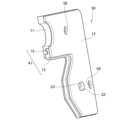
- FIG. 3 is a perspective view showing a first holding member constituting the side seal.
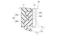
- FIG. 4A is an enlarged cross-sectional view of a portion of the side seal prior to assembly.
- FIG. 4B is an enlarged cross-sectional view of a portion of the side seal during or after assembly.
- FIG. 5 is a schematic diagram showing a side seal according to an embodiment of the present invention.
- FIG. 6A is a schematic diagram showing an initial state of a side seal according to an embodiment of the present invention.
- FIG. 6B is a schematic diagram showing a state in which the second holding member is inclined in the side seal according to the embodiment of the present invention.
- FIG. 7A is a schematic diagram showing an example of the relationship between the fitting protrusion and the fitting hole.
- FIG. 7B is a schematic diagram showing another example of the relationship between the fitting protrusion and the fitting hole.
- FIG. 7C is a schematic diagram showing another example of the relationship between the fitting protrusion and the fitting hole.
- FIG. 7D is a schematic diagram showing another example of the relationship between the fitting protrusion and the fitting hole.
- FIG. 7E is a schematic diagram showing another example of the relationship between the fitting protrusion and the fitting hole.
- FIG. 7F is a schematic diagram showing another example of the relationship between the fitting protrusion and the fitting hole.
- FIG. 7A is a schematic diagram showing an example of the relationship between the fitting protrusion and the fitting hole.
- FIG. 7B is a schematic diagram showing another example of the relationship between the fitting protrusion and
- FIG. 8 is a schematic diagram for explaining a problem that occurs when assembling a conventional linear guide.
- FIG. 9 is an enlarged schematic view of a conventional side seal.
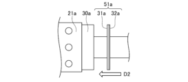
- FIG. 10A is a schematic diagram showing a conventional side seal when it is moved in the direction indicated by the arrow D2.
- FIG. 10B is a schematic diagram showing a state where a conventional side seal is moved in the direction indicated by an arrow D5.
- FIG. 10C is a schematic diagram showing a conventional side seal in an exploded state.
- FIG. 1 is a perspective view showing a linear guide 1 according to an embodiment of the present invention.
- the linear guide 1 comprises a guide rail 3 extending in one direction, and a slider 20 with a C-shaped cross section that is mounted across the guide rail 3 so as to be movable relative to the guide rail 3 in the axial direction.
- the left-right direction refers to the width direction of the slider 20 attached to the guide rail 3.
- the guide rail 3 is made of metal, and two rail-side track surfaces 5 are formed on each of the left and right side surfaces 3b along the axial direction of the guide rail 3.
- the guide rail 3 has multiple rail mounting holes 4 that penetrate the guide rail 3 in the height direction, and rail fixing bolts (not shown) are inserted into these rail mounting holes 4 to fix the guide rail 3 to a mounting surface (not shown).
- the slider 20 comprises a slider body 21 having sleeves on both the left and right sides of the guide rail 3, a pair of end caps 30, 30 attached to both ends of the slider body 21 in the moving direction, and return guides (not shown) each assembled into the end caps 30, 30.
- a plurality of rolling bodies are filled in the rolling body rolling path formed inside the slider 20 and between the slider 20 and the rail side raceway surface 5 of the guide rail 3 so that they can roll freely.
- the rolling bodies roll, allowing the slider 20 to move axially relative to the guide rail 3.
- These rolling bodies circulate endlessly while rolling within the rolling body rolling path in accordance with the relative movement between the guide rail 3 and the slider 20.
- the top surface of the slider body 21 is provided with screw insertion holes 25 through which bolts for fixing a driven body such as a table to the slider 20 are inserted.
- the end caps 30 attached to both ends of the slider body 21 in the moving direction are, for example, injection molded products made of synthetic resin, and are formed with a C-shaped cross section like the slider body 21.
- a grease nipple 6 for supplying grease or the like to the inside of the slider 20 is attached to the end caps 30.
- a pair of side seals 50, 50 are arranged on the end faces of the slider 20 in the moving direction.
- the side seal 50 seals the gap between the guide rail 3 and the slider 20, and serves to prevent foreign matter such as dirt, dust, and dirt from entering the inside of the slider 20.
- the side seal 50 has a number of mounting screw insertion holes 58 (see FIG. 2), and the end cap 30 also has mounting screw insertion holes (not shown).
- the side seal 50 is joined to the movement direction end face of the slider 20, which has the end cap 30 and the slider body 21, by inserting the mounting screws 35 through the mounting screw insertion holes 58, etc., provided in the side seal 50 and the end cap 30.
- FIG. 2 is a perspective view showing a side seal 50 joined to the end surface in the movement direction of the slider 20 shown in FIG. 1.
- FIG. 3 is a perspective view showing a first retaining member 11 constituting the side seal 50.
- FIG. 4A is an enlarged cross-sectional view showing a portion of the side seal before assembly work
- FIG. 4B is an enlarged cross-sectional view showing a portion of the side seal during or after assembly work. Note that FIG. 2 shows the side seal 50 divided into two in the left-right direction.
- the side seal 50 is an assembly in which parts made of different materials are combined and integrated, and is formed in a C-shape in plan view, similar to the cross-sectional shape of the slider body 21.
- the side seal 50 has a seal member 41 that slides against the guide rail 3, and a first holding member (holding plate) 11 and a second holding member (seal cover) 12 that sandwich the seal member 41.
- the first holding member 11 is disposed closer to the slider 20 than the seal member 41, and the second holding member 12 is disposed on the opposite side of the seal member 41 to the side on which the first holding member 11 is disposed.
- seal member 41, the first holding member 11, and the second holding member 12 are not an integral type that is fixed to each other in advance, but are assembled by inserting the fitting protrusion 22 of the first holding member 11, which will be described later, into the fitting hole 23 of the second holding member 12.
- the seal member 41 is made of a material such as polyester elastomer.
- the seal member 41 has a shape that follows the shape of the side and top surfaces of the guide rail 3, and has a lip portion 13 that slides against the guide rail 3, and a base portion 15 that is sandwiched between the first holding member 11 and the second holding member 12.
- the holding portion 46 that holds the seal member 41 in the first holding member 11 has a recess 26a and a protrusion 26b that extend along the shape of the seal member 41.
- the base portion 15 of the seal member 41 has a protrusion 45a and a recess 45b that are shaped to fit into the recess 26a and the protrusion 26b formed in the first holding member 11.
- the seal member 41 is held by the first holding member 11 by fitting the recess 26a and the protrusion 26b to the protrusion 45a and the recess 45b.
- the lip portion 13 that extends from the base 15 of the seal member 41 toward the guide rail 3 is inclined outward, i.e., in the direction away from the slider 20, as it approaches the guide rail 3.
- the first holding member 11 is made of a material such as polyacetal or nylon, and is flexible.
- the second holding member 12 is made of a metal such as steel or aluminum.
- the first holding member 11 has two fitting projections 22 (see FIG. 3) that protrude toward the second holding member 12, and the second holding member 12 has two fitting holes 23 into which the fitting projections 22 of the first holding member 11 are fitted.
- the fitting projections 22 are fitted into the fitting holes 23, so that the second holding member 12 presses the seal member 41 against the first holding member 11, and the first holding member 11, the seal member 41, and the second holding member 12 are integrated to form a side seal 50.
- the lip portion 13 of the single side seal 50 before assembly is in a state where no external force is being applied, and it maintains the shape it had at the time of manufacture.
- the side seal 50 is attached to the slider 20, the lip portion 13 is pressed against the guide rail 3 and deforms in a more inclined direction.
- the lip portion 13 moves in the grain direction, so the frictional force between the lip portion 13 and the guide rail 3 is small. Also, since the first holding member 11 is moved while being pressed against almost the entire surface by the second metallic holding member 12, the first holding member 11 and the second holding member 12 do not come off.
- the first retaining member 11 when the side seal 50 is moved in the direction of the arrow D11 (direction away from the slider), the first retaining member 11 is configured to bend in a bow shape.
- the axial direction of the fitting protrusion 22 is inclined so that the tip of the fitting protrusion 22 approaches the guide rail 3 side, and the angle difference with the axial direction of the fitting hole 23 of the second retaining member 12 increases.
- the first retaining member 11 deforms, a fixing force is generated between the fitting protrusion 22 and the fitting hole 23 by prying, and the contact pressure between the fitting protrusion 22 and the fitting hole 23 increases.
- the fitting protrusion 22 also bites into the corner of the fitting hole 23 on the far side from 11. As a result, it is possible to prevent the fitting protrusion 22 from coming out of the fitting hole 23. Additionally, as described below, it is more preferable that the length of the fitting protrusion 22 is longer than the depth of the fitting hole 23.
- the first retaining member 11 is made of a flexible material
- the second retaining member 12 and the end cap 30 are made of a material that has sufficient rigidity and does not easily deform. Therefore, after the side seal 50 is fixed to the slider body 21 together with the end cap 30 by the mounting screw 35, the side seal 50 hardly bends due to the frictional force between the lip portion 13 and the guide rail 3, and the desired sealing performance can be maintained.
- the cross-sectional shape of the fitting protrusion 22 and the cross-sectional shape of the fitting hole 23 are approximately the same, and it is preferable that the tip of the fitting protrusion 22 does not have a locking portion such as a hook or claw that locks into the fitting hole 23.
- the unnecessary side seal 50 can be disassembled into the first retaining member 11, the seal member 41, and the second retaining member 12 even more easily without using special tools.
- the tip of the fitting protrusion 22 may be chamfered for reasons such as making it easier to insert the fitting protrusion 22 into the fitting hole 23.
- a method for increasing the contact pressure between the fitting protrusion 22 and the fitting hole 23 as the first retaining member 11 deforms and preventing the fitting protrusion 22 from slipping out of the fitting hole 23 for example, a method for adjusting the gap between the two can be mentioned. Specifically, as shown in FIG. 6B, while one end of the first retaining member 11 and the second retaining member 12 are kept in contact, the first retaining member 11 and the second retaining member 12 are separated at a portion separated from this end. Then, the fitting protrusion 22 and the fitting hole 23 are designed to come into contact with each other when the angle between the first retaining member 11 and the second retaining member 12 is set to 1°.
- the fitting protrusion 22 is formed longer than the axial length of the fitting hole 23. That is, if the fitting protrusion 22 protrudes from the surface of the second holding member 12 opposite to the first holding member 11 side, the more the first holding member 11 bends, the stronger the fitting protrusion 22 of the first holding member 11 hits the fitting hole 23 of the second holding member 12. As a result, the effect of preventing coming out can be further improved, and the side seal 50 can be assembled to the slider 20 without disassembling the first holding member 11 and the second holding member.
- the fitting protrusion 22 when the second holding member 12 is produced by press molding, sheared surfaces and fractured surfaces are formed on the inner wall of the fitting hole 23 by the press processing.
- the fitting force changes depending on whether the surface of the second holding member 12 facing the first holding member 11 is the sheared surface side or the fractured surface side.
- the axial length of the fitting protrusion 22 if the axial length of the fitting protrusion 22 is formed longer than the axial length of the fitting hole 23, an excellent fitting force can be obtained regardless of the orientation in which the second holding member 12 is arranged.
- the second holding member 12 has a shape that is symmetrical from left to right or from top to bottom, it is not necessary to consider the front and back when arranging the second holding member 12, which improves workability during assembly.
- FIG. 7A to 7F are schematic diagrams showing examples of the relationship between the fitting protrusions and the fitting holes.
- the fitting protrusion 22a may have a smaller diameter than the fitting hole 23a, and may have a clearance fit with a gap C.
- the fitting protrusion 22b and the fitting hole 23b may have a close fit relationship in which the fitting protrusion 22b has a larger diameter to the extent that they can be fitted together, or in which the fitting protrusion 22b has a larger diameter to the extent that they can be fitted together. Also, as shown in FIG.
- the fitting protrusion 22c and the fitting hole 23c may have a close fit relationship in which the cross-sectional shapes of the fitting protrusion 22c and the fitting hole 23c are different from each other.
- the distance P1 between the two fitting protrusions 22d is smaller than the distance P2 between the two fitting holes 23d, and a partial gap may be present.
- one of the fitting protrusions 221e and the fitting hole 231e may have an interference fit relationship, and the other of the fitting protrusions 222e and the fitting hole 232e may have a clearance fit relationship.
- fitting protrusions and fitting holes does not need to be two each, and multiple fitting protrusions and fitting holes may be provided.
- three fitting protrusions 221f, 222f, and 223f and three fitting holes 231f, 232f, and 233f may be provided.
- the shapes and sizes of the fitting protrusions 221f, 222f, and 223f and the fitting holes 231f, 232f, and 233f may be in any combination.
- fitting protrusions 221f and the fitting holes 231f may be in an interference fit relationship
- fitting protrusions 222f and the fitting holes 232f, and the fitting protrusions 223f and the fitting holes 233f may all be in a clearance fit relationship.
- the first retaining member 11 is preferably designed to bend 5 to 20 degrees due to the frictional force generated between the lip portion 13 and the guide rail 3 when it is moved in a direction away from the slider 20.
- the side seal 50 is an assembly, but can be easily assembled and disassembled without the use of special tools. This allows the components that make up the side seal 50 to be easily separated and disposed of or recycled, even if they are made of different materials. Furthermore, when assembling the side seal 50 to the slider 20, even if the frictional force between the lip portion 13 and the guide rail 3 is large, the side seal 50 can be easily attached to the slider 20 without disassembling the first retaining member 11 and the second retaining member.
- the first retaining member 11 is provided with an engagement protrusion 22, the second retaining member 12 is provided with an engagement hole 23, and the engagement protrusion 22 is engaged with the engagement hole 23, but the present invention is not limited to this.
- Either one of the first retaining member 11 and the second retaining member 12 may be provided with a plurality of engagement protrusions 22 that protrude toward the other retaining member, and the other retaining member may be provided with a plurality of engagement holes 23 into which the plurality of engagement protrusions 22 are engaged.
- the second retaining member 12 may be provided with an engagement protrusion 22, the first retaining member 11 may be provided with an engagement hole 23, and the engagement protrusions 22 may be engaged with the engagement hole 23.
- the linear guide according to this embodiment is equipped with the side seal 50 according to the above embodiment.
- the side seal 50 which can be easily assembled and disassembled, it is possible to improve workability when assembling and disassembling the linear guide, and also to improve recyclability.
- the present invention is not limited to the above-described embodiment, and can be modified, improved, etc. as appropriate.
- the material, shape, dimensions, values, form, number, location, etc. of each component in the above-described embodiment are arbitrary and not limited as long as they can achieve the present invention.
Landscapes
- Engineering & Computer Science (AREA)
- General Engineering & Computer Science (AREA)
- Mechanical Engineering (AREA)
- Bearings For Parts Moving Linearly (AREA)
- Sealing Devices (AREA)
- Sealing Of Bearings (AREA)
Abstract
サイドシール(50)は、案内レール(3)に摺接するシール部材(41)と、シール部材(41)よりもスライダ(20)に取り付けられ、シール部材(41)を保持する第1保持部材(11)と、第1保持部材(11)とともにシール部材(41)を挟持する第2保持部材(12)と、を有する。第1保持部材(11)は、第2保持部材(12)に向かって突出する複数の嵌合用突起(22)を有し、第2保持部材(12)は、複数の嵌合用突起(22)が嵌入される複数の嵌合用穴(23)を有し、嵌合用突起(22)が嵌合用穴(23)に嵌合されることにより、サイドシール(50)が一体化している。第1保持部材(11)は可撓性を有し、第1保持部材(11)の変形に伴って、嵌合用突起(22)と嵌合用穴(23)との接触圧が増大する。
Description
本発明は、サイドシール及びリニアガイドに関する。
一般的に、リニアガイドは、軸方向に延びる案内レールと、案内レールに相対移動可能に跨架されたスライダと、を備える。そして、案内レール及びスライダに形成された転動体転動溝間を循環する複数の転動体(ボール)を介して、スライダが案内レール上を軸方向に相対移動する。このようなリニアガイドは、各種生産設備の直線移動機構に多用されている。
また、スライダには、案内レールが延びる方向の両端面に、案内レールとスライダとの間を塞ぎ、ごみ、埃、塵などの異物がスライダの内部に侵入するのを防止するサイドシールが取り付けられている。
近時、シール性能や耐久性等の向上を目的として、種々の構造を有するサイドシールが提案されている。例えば、特許文献1には、スライダにおける摺動方向の端面に取り付けられた取付プレートのコ字形溝内に、ガイドレールに摺接する溝部を有する摺動スクレーパーが嵌着されたリニアガイド装置が記載されている。摺動スクレーパーには、取付プレートに嵌着させるための突起部及び凹部が形成されており、突起部や凹部の大きさや形状、あるいは摺動スクレーパーの外面に形成する位置を変更することで、ガイドレールに当接する力を調節することができる。
また、特許文献2には、スライダと案内レールの上面および両側面との間をリップ部により密封するサイドシールが開示されている。サイドシールは、リップ部を独立に有する複数枚のシール部材を有し、複数枚のシール部材は、直動方向に垂直な方向に相対移動可能に結合されている。また、複数枚のシール部材は、互いに係合する凸部と凹部とで結合され、凸部および凹部は、各シール部材に一体に形成されている。
さらに、特許文献3には、ホルダケースと、このホルダケース内に配設された少なくとも1枚の板状のシールプレートと、封止プレートから構成された高密封シール装置が提案されている。シールプレートは、メカニカルフロスウレタンフォームから構成され、シールプレート自体が両側面の表層を形成するゴム状のスキン層と、表層間の中間層を形成するスポンジ層から成る3層構造で構成されている。
ところで、近時、環境負荷の少ない製品作りが要求されており、リニアガイドの分野においても、容易に材料ごとに分別し、廃棄又はリサイクルすることができる部品についての検討が行われている。上記特許文献1~特許文献3においては、いずれも、シール部材と、このシール部材を支持する部品とが別体となっており、容易に分別することができる。
しかしながら、上記特許文献1及び特許文献3に記載のサイドシールは、各部品が一体化されておらず、スライダの両端部に取り付ける際に作業が煩雑になる。
これに対して、上記特許文献2に記載の複数枚のシール部材は、互いに係合する凸部と凹部とで結合され、一体化されている。シール部材の輸送時や保管時においては、一体化されたシール部材が積み重ねられて梱包管理されているため、一体化されたシール部材が外れることはない。
しかし、シール部材を案内レールに挿入して移動させる際には、シール部材と案内レールとの間の摩擦が大きくなり、一体化された各シール部材が分離して、取り付け作業に時間を要することになり、作業効率が低下する場合がある。
図8は、従来のリニアガイドを組み立てる際に発生する問題点を説明するための模式図である。また、図9及び図10A~図10Cは、従来のサイドシールを拡大して示す模式図である。
図8に示すように、軸方向に延びる案内レール3に、第1スライダ20a及び第2スライダ20bを組み込む場合について説明する。第1スライダ20aは、第1スライダ本体21aと、第1スライダ本体21aの移動方向両端面に配置されたエンドキャップ30a、30aと、を有し、第1スライダ20aのさらに移動方向両端部には、サイドシール50a、51aが配置されている。また、第2スライダ20bは、第2スライダ本体21bと、第2スライダ本体21bの移動方向両端面に配置されたエンドキャップ30b、30bと、を有し、第2スライダ20bのさらに移動方向両端部には、サイドシール50b、51bが配置されている。
サイドシール50a、51aは、それぞれ、第1スライダ本体21a側に配置される保持板11a、31aと、保持板11a、31aよりも外側に配置されるシールカバー12a、32aと、保持板11a、31aとシールカバー12a、32aとに挟持されるシール部材41a、42aを有する。シール部材41a、42aは、それぞれ、保持板11a、31aに保持される基部15a、16aと、案内レール3に摺接するリップ部13a、14aと、を有する。また、保持板11a、31aとシールカバー12a、32aとは、何らかの不図示の係合部によって係合され、サイドシール50a、51aは、それぞれ一体化した構造となっている。なお、リップ部13a及びリップ部14aは、第1スライダ20aの内部にごみ、埃、塵などの異物が侵入するのを防止する役割を果たすため、案内レール3に近づくにつれて外方に傾斜するように構成されている。
サイドシール50b、51bについても同様に、それぞれ、第2スライダ本体21b側に配置される保持板11b、31bと、保持板11b、31bよりも外側に配置されるシールカバー12b、32bと、保持板11b、31bとシールカバー12b、32bとに挟持されるシール部材41b、42bを有する。シール部材41b、42bは、それぞれ、保持板11b、31bに保持される基部15b、16bと、案内レール3に摺接するリップ部13b、14bと、を有する。また、保持板11b、31bとシールカバー12b、32bとは、何らかの不図示の係合部によって係合され、サイドシール50b、51bは、それぞれ一体化した構造となっている。なお、リップ部13b及びリップ部14bは、第2スライダ20bの内部にごみ、埃、塵などの異物が侵入するのを防止する役割を果たすため、案内レール3に近づくにつれて外方に傾斜するように構成されている。
上記リニアガイド1を組み立てる際に、例えば、第1スライダ20aを、矢印D1で示す方向で案内レール3に沿って移動させる。次に、サイドシール50aを、矢印D1に示す方向で移動させ、第1スライダ20aに固定する。その後、サイドシール51aを、矢印D2で示す方向で案内レール3に沿って移動させた後、これを第1スライダ20aに固定する。その後、第2スライダ20bにサイドシール50bを取り付けるため、予め、サイドシール50bを矢印D3で示す方向に移動させ、所望の位置に配置しておく。その後、第2スライダ20bを、矢印D3で示す方向に移動させた後、サイドシール50bを第2スライダ20bに固定する。その後、サイドシール51bを、矢印D4で示す方向に移動させた後、これを第2スライダ20bに固定する。
上記のように、2以上のスライダを案内レール3に組み込む場合に、サイドシール50a、51a、51bの移動時においては、リップ部13a、14a、14bと案内レール3との間の摩擦力が小さい方向(以下、順目方向という。)に移動される。一方、サイドシール50bの移動時においては、リップ部13bの先端が移動方向に向かっており、リップ部13bと案内レール3との間の摩擦力が大きい方向(以下、逆目方向という。)に移動される。
このような場合に、図9に示すように、リップ部13bと案内レール3との大きい摩擦力によって保持板11bが弓なりに撓み、保持板11bとシールカバー12bとの間に隙間17が生じる。その結果、一体化していたサイドシール50bが、保持板11bとシールカバー12bとに分解されてしまうことがあり、再び一体化させる必要があるため、作業効率が低下する。
また、例えば、順目方向に移動させるサイドシール51aであっても、同様の問題点が発生する。通常の組立作業では、図10Aに示すように、サイドシール51aを、矢印D2で示す方向に移動させる。しかし、組立中に作業者が手を持ち替えたり、サイドシール51aの位置を微調整する際に、図10Bに示すように、矢印D5で示す逆目方向に移動させる作業が生じることがある。その結果、図10Cに示すように、サイドシール50bが、保持板31aとシールカバー32aとに分解されてしまうことがある。このような場合には、保持板31aとシールカバー32aとを不図示の係合部で位置合せして、一体化させる作業が発生し、組立効率が低下する。
組立作業時においてもサイドシールが分解されないように、係合部を鉤爪(スナップフィット)構造としたサイドシールも公知であるが、各部品を強固に結合させてしまうと、リサイクル時の分解作業に手間がかかる。
本発明は、かかる問題点に鑑みてなされたものであって、シール部材と、シール部材を挟持する部材とが一体化したサイドシールにおいて、特別な道具を使用することなく組立が可能であり、スライダへの取り付け時における作業効率が優れ、容易に分解できることでリサイクル性を向上させることができるサイドシール、及びこのサイドシールを備えるリニアガイドを提供することを目的とする。
本発明の上記目的は、下記の構成により達成される。
(1) 案内レールと、前記案内レールに相対移動可能に跨架されるスライダと、を有するリニアガイドにおける、前記スライダの移動方向端面に接合されるサイドシールであって、
前記案内レールに摺接するシール部材と、
前記シール部材よりも前記スライダ側に取り付けられ、前記シール部材を保持する第1保持部材と、
前記シール部材における前記第1保持部材側と反対側に取り付けられ、前記第1保持部材とともに前記シール部材を挟持する第2保持部材と、を有し、
前記第1保持部材及び前記第2保持部材のうち、いずれか一方の保持部材は、他方の保持部材に向かって突出する複数の嵌合用突起を有し、他方の保持部材は、前記複数の嵌合用突起が嵌入される複数の嵌合用穴を有し、前記嵌合用突起は前記嵌合用穴に嵌合されており、
前記第1保持部材は可撓性を有するものであり、
前記第1保持部材の変形に伴って、前記嵌合用突起と前記嵌合用穴との接触圧が増大するように構成されている、サイドシール。
(2) 前記第1保持部材は前記嵌合用突起を有し、
前記第1保持部材が変形した場合に、前記嵌合用突起の軸方向が傾斜して、前記嵌合用突起と前記嵌合用穴との接触圧が増大する、(1)に記載のサイドシール。
(3) 前記第1保持部材は前記嵌合用穴を有し、
前記第1保持部材が変形した場合に、前記嵌合用穴の軸方向が傾斜して、前記嵌合用突起と前記嵌合用穴との接触圧が増大する、(1)に記載のサイドシール。
(4) 前記嵌合用突起は、前記他方の保持部材の表面から突出している、(1)~(3)のいずれか1つに記載のサイドシール。
(5) 前記スライダの移動方向に平行な断面視において、前記嵌合用突起の断面形状と前記嵌合用穴の断面形状とは略同一である、(1)~(4)のいずれか1つに記載のサイドシール。
(6) 前記嵌合用突起及び前記嵌合用穴は、前記シール部材と前記案内レールとが摺接する面から離隔した位置に配置されている、(1)~(5)のいずれか1つに記載のサイドシール。
(7) (1)~(6)のいずれか1つに記載のサイドシールを備えるリニアガイド。
(1) 案内レールと、前記案内レールに相対移動可能に跨架されるスライダと、を有するリニアガイドにおける、前記スライダの移動方向端面に接合されるサイドシールであって、
前記案内レールに摺接するシール部材と、
前記シール部材よりも前記スライダ側に取り付けられ、前記シール部材を保持する第1保持部材と、
前記シール部材における前記第1保持部材側と反対側に取り付けられ、前記第1保持部材とともに前記シール部材を挟持する第2保持部材と、を有し、
前記第1保持部材及び前記第2保持部材のうち、いずれか一方の保持部材は、他方の保持部材に向かって突出する複数の嵌合用突起を有し、他方の保持部材は、前記複数の嵌合用突起が嵌入される複数の嵌合用穴を有し、前記嵌合用突起は前記嵌合用穴に嵌合されており、
前記第1保持部材は可撓性を有するものであり、
前記第1保持部材の変形に伴って、前記嵌合用突起と前記嵌合用穴との接触圧が増大するように構成されている、サイドシール。
(2) 前記第1保持部材は前記嵌合用突起を有し、
前記第1保持部材が変形した場合に、前記嵌合用突起の軸方向が傾斜して、前記嵌合用突起と前記嵌合用穴との接触圧が増大する、(1)に記載のサイドシール。
(3) 前記第1保持部材は前記嵌合用穴を有し、
前記第1保持部材が変形した場合に、前記嵌合用穴の軸方向が傾斜して、前記嵌合用突起と前記嵌合用穴との接触圧が増大する、(1)に記載のサイドシール。
(4) 前記嵌合用突起は、前記他方の保持部材の表面から突出している、(1)~(3)のいずれか1つに記載のサイドシール。
(5) 前記スライダの移動方向に平行な断面視において、前記嵌合用突起の断面形状と前記嵌合用穴の断面形状とは略同一である、(1)~(4)のいずれか1つに記載のサイドシール。
(6) 前記嵌合用突起及び前記嵌合用穴は、前記シール部材と前記案内レールとが摺接する面から離隔した位置に配置されている、(1)~(5)のいずれか1つに記載のサイドシール。
(7) (1)~(6)のいずれか1つに記載のサイドシールを備えるリニアガイド。
本発明のサイドシールによれば、特別な道具を使用することなく組立が可能であり、スライダへの取り付け時における作業効率が優れ、容易に分解できることでリサイクル性を向上させることができる。また、本発明のリニアガイドによれば、上記のように優れた性能を有するサイドシールを備えるため、組立時の作業効率及びリサイクル性を向上させることができる。
以下、本発明に係るサイドシールおよびリニアガイドの実施形態を図面に基づいて詳細に説明する。なお、本発明は、以下に説明する実施形態に限定されるものではなく、本発明の要旨を逸脱しない範囲において、任意に変更して実施することができる。
図1は、本発明の実施形態に係るリニアガイド1を示す斜視図である。リニアガイド1は、一方向に延びる案内レール3と、案内レール3に対して軸方向に相対移動可能に跨架され、断面C字状のスライダ20と、を備えている。なお、本実施形態において、左右方向とは、案内レール3に取り付けられたスライダ20の幅方向を表す。
案内レール3は金属製で、その左右の側面3bには、レール側軌道面5が案内レール3の軸方向に沿って二条ずつ形成されている。案内レール3は案内レール3の高さ方向に貫通する複数のレール取付孔4を有しており、これらのレール取付孔4には、案内レール3を不図示の被取付面に固定する不図示のレール固定用ボルトが挿入される。
スライダ20は、案内レール3の左右両側に袖部を有するスライダ本体21と、スライダ本体21の移動方向の両端部に装着された一対のエンドキャップ30,30と、これらのエンドキャップ30,30内に一組ずつ組み込まれた不図示のリターンガイドと、を備える。スライダ20の内部及びスライダ20と案内レール3のレール側軌道面5との間に構成された転動体転動路には、複数個の不図示の転動体が転動自在に充填されている。この転動体が転動することにより、スライダ20が案内レール3に対して軸方向に相対移動可能となっている。そして、これら複数の転動体は、案内レール3とスライダ20との相対移動に伴って、転動体転動路内を転動しながら無限循環する。
スライダ本体21の上面には、スライダ20にテーブル等の被駆動体を固定するボルトを挿通させるねじ挿通孔25が設けられている。スライダ本体21の移動方向の両端部にそれぞれ装着されたエンドキャップ30は、例えば、合成樹脂材の射出成形品であって、スライダ本体21と同様に断面C字状に形成されている。エンドキャップ30には、スライダ20の内部にグリース等を供給するためのグリースニップル6が取付けられている。また、スライダ20の移動方向端面には、一対のサイドシール50,50が配置されている。
サイドシール50は、案内レール3とスライダ20との間を塞ぎ、ごみ、埃、塵などの異物がスライダ20の内部に侵入するのを防止する役割を果たす。サイドシール50には、複数の取付ねじ挿通孔58(図2参照)が設けられており、エンドキャップ30にも、不図示の取付ねじ挿通孔が設けられている。そして、サイドシール50及びエンドキャップ30に設けられた取付ねじ挿通孔58等に取付ねじ35が挿通されることにより、サイドシール50が、エンドキャップ30とスライダ本体21とを有するスライダ20の移動方向端面に接合される。
図2は、図1に示すスライダ20の移動方向端面に接合されるサイドシール50を示す斜視図である。図3は、サイドシール50を構成する第1保持部材11を示す斜視図である。また、図4Aは、組立作業前のサイドシールの一部を拡大して示す断面図であり、図4Bは、組立作業中又は組立作業後のサイドシールの一部を拡大して示す断面図である。なお、図2においては、サイドシール50を左右方向で2分割したものを示している。
図2及び図3に示すように、サイドシール50は、材質が互いに異なる部品を組み合わせて一体化させた組立体であり、スライダ本体21の断面形状と同様に、平面視でC字状に形成されている。サイドシール50は、案内レール3に摺接するシール部材41と、このシール部材41を挟持する第1保持部材(保持板)11及び第2保持部材(シールカバー)12を有する。第1保持部材11は、シール部材41よりもスライダ20側に配置され、第2保持部材12は、シール部材41における第1保持部材11が配置された側と反対側に配置されている。なお、これらのシール部材41、第1保持部材11及び第2保持部材12は、あらかじめ互いに固着された一体型ではなく、後述する第1保持部材11の嵌合用突起22を第2保持部材12の嵌合用穴23に挿入することにより組み立てられた組立体である。
シール部材41は、ポリエステルエラストマー等の材質からなる。シール部材41は、案内レール3の軸方向に直交する断面視で、案内レール3の側面及び上面の形状に沿った形状を有し、案内レール3に摺接するリップ部13と、第1保持部材11と第2保持部材12とに挟持される基部15と、を有する。図4A及び図4Bに示すように、第1保持部材11におけるシール部材41を保持する保持部46には、シール部材41の形状に沿って延びる凹部26a及び凸部26bが形成されている。また、シール部材41の基部15には、第1保持部材11に形成された凹部26a及び凸部26bに嵌合する形状の凸部45a及び凹部45bが形成されている。そして、凹部26a及び凸部26bと、凸部45a及び凹部45bとが嵌合されることにより、シール部材41は第1保持部材11に保持されている。なお、シール部材41の基部15から案内レール3に向かって延びるリップ部13は、案内レール3に近づくにつれて、外方、すなわち、スライダ20から離隔する方向に向かって傾斜している。
第1保持部材11は、ポリアセタール、ナイロン等の材質からなり、可撓性を有する。また、第2保持部材12は、例えば金属製であり、鉄鋼、アルミニウム等の材質からなる。本実施形態において、第1保持部材11は、第2保持部材12に向かって突出する2つの嵌合用突起22(図3参照)を有し、第2保持部材12は、第1保持部材11の嵌合用突起22が嵌入される2つの嵌合用穴23を有する。そして、嵌合用突起22が嵌合用穴23に嵌合されており、これにより、第2保持部材12によりシール部材41が第1保持部材11側に押し付けられるとともに、第1保持部材11、シール部材41及び第2保持部材12が一体化され、サイドシール50が構成されている。
図4Aに示すように、組立作業前の単独のサイドシール50におけるリップ部13は、外部から力が付加されていない状態であり、製造時の形状を保っている。一方、サイドシール50をスライダ20に取り付ける際には、リップ部13が案内レール3に押し付けられて、より傾斜する方向に変形する。
ここで、組立作業時において、サイドシール50を、取り付ける対象となるスライダ20の方向に移動させる場合には、リップ部13は順目方向に移動するため、リップ部13と案内レール3との摩擦力は小さい。また、金属製の第2保持部材12によって第1保持部材11の略全面を押圧させつつ移動させるため、第1保持部材11と第2保持部材12とが外れることはない。
しかし、サイドシール50を、スライダ20から離隔する方向に移動させる場合には、図4Bに示すように、リップ部13は案内レール3に押し付けられた状態で逆目方向に移動するため、リップ部13と案内レール3との摩擦力は著しく大きくなる。従来のサイドシールでは、図9に示すように、保持板11bが移動方向に追従できなくなり、シールカバー12bが保持板11bから外れようとする。
これに対して、本実施形態においては、図5に示すように、サイドシール50を矢印D11方向(スライダから離隔する方向)に移動させた場合に、第1保持部材11が弓なりに撓むように構成されている。これにより、嵌合用突起22の先端が案内レール3側に近づくように、嵌合用突起22の軸方向が傾斜して、第2保持部材12の嵌合用穴23の軸方向との角度差が増大する。すなわち、第1保持部材11の変形に伴って、嵌合用突起22と嵌合用穴23との間でこじりによる固定力が発生し、嵌合用突起22と嵌合用穴23との接触圧が増大する。また、嵌合用突起22の軸方向と嵌合用穴23の軸方向との角度差が増大することによって、嵌合用突起22が嵌合用穴23の11から遠い側の角部への食い込みも発生する。その結果、嵌合用穴23から嵌合用突起22が抜けることを防止することができる。また、後述するように、嵌合用突起22の長さは、嵌合用穴23の深さよりも長いことがより好ましい。
なお、本実施形態において、第1保持部材11は可撓性を有する材料からなるが、第2保持部材12及びエンドキャップ30は十分な剛性を有し、容易に変形しない材料からなる。したがって、取付ねじ35によってサイドシール50をエンドキャップ30とともにスライダ本体21に固定した後に、サイドシール50がリップ部13と案内レール3との間の摩擦力によって撓むことはほとんどなく、所望のシール性能を維持することができる。
また、本実施形態において、スライダ20の移動方向に平行な断面視で、嵌合用突起22の断面形状と嵌合用穴23の断面形状とは略同一であり、嵌合用突起22の先端に、嵌合用穴23に係止される鉤や爪のような係止部が形成されていないことが好ましい。このような構成であると、不要となったサイドシール50に対して特別な道具等を使用することなく、より一層容易に第1保持部材11、シール部材41及び第2保持部材12に分解することができる。なお、嵌合用突起22を嵌合用穴23に挿入しやすくする等の理由で、嵌合用突起22の先端等に面取りが行われていてもよい。
嵌合用突起22と嵌合用穴23との好ましい関係について、図6A及び図6Bを参照して具体的に説明する。図6Aに示す初期状態においては、第1保持部材11と第2保持部材12とが互いに平行となるように配置され、例えば、嵌合用突起22と嵌合用穴23との関係は、すきまばめとなっている。
第1保持部材11の変形に伴って、嵌合用突起22と嵌合用穴23との接触圧を増大させ、嵌合用穴23から嵌合用突起22が抜けないようにする方法として、例えば、両者の間のすきまを調整する方法が挙げられる。具体的には、図6Bに示すように、第1保持部材11と第2保持部材12との一端部を接触させた状態のまま、この一端部から離隔した部分において、第1保持部材11と第2保持部材12とを離隔させる。そして、第1保持部材11と第2保持部材12とがなす角度を1°とした状態で、嵌合用突起22と嵌合用穴23とが接触するように設計する。
このように構成されたサイドシール50においては、第1保持部材11が撓んで、第2保持部材12との間に空間が形成された場合に、嵌合用突起22が嵌合用穴23に接触して、両者間の接触圧が増大する。したがって、嵌合用穴23から嵌合用突起22が抜けることを抑制することができる。
なお、嵌合用突起22と嵌合用穴23とが高い接触圧で接触していた場合であっても、
両者の間で若干の滑りが発生する。したがって、滑りが発生しても嵌合用穴23から嵌合用突起22が抜けることをより一層防止するため、嵌合用突起22の軸方向の長さを、嵌合用穴23の軸方向の長さよりも長く形成することが好ましい。すなわち、嵌合用突起22が、第2保持部材12における第1保持部材11側と反対側の表面から突出していると、第1保持部材11が撓めば撓むほど第1保持部材11の嵌合用突起22が第2保持部材12の嵌合用穴23に強く当たる効果が得られる。その結果、より一層抜け防止の効果を向上させることができ、第1保持部材11と第2保持部材とが分解されることなくサイドシール50をスライダ20に組付けることが可能となる。
両者の間で若干の滑りが発生する。したがって、滑りが発生しても嵌合用穴23から嵌合用突起22が抜けることをより一層防止するため、嵌合用突起22の軸方向の長さを、嵌合用穴23の軸方向の長さよりも長く形成することが好ましい。すなわち、嵌合用突起22が、第2保持部材12における第1保持部材11側と反対側の表面から突出していると、第1保持部材11が撓めば撓むほど第1保持部材11の嵌合用突起22が第2保持部材12の嵌合用穴23に強く当たる効果が得られる。その結果、より一層抜け防止の効果を向上させることができ、第1保持部材11と第2保持部材とが分解されることなくサイドシール50をスライダ20に組付けることが可能となる。
また、第2保持部材12がプレス成形により作製されたものである場合に、嵌合用穴23の内壁に、プレス加工によるせん断面と破断面が形成される。嵌合用突起22が、第2保持部材12の厚さよりも薄い場合、第2保持部材12における第1保持部材11に対向する面が、せん断面側であるか破断面側であるかによって、嵌合力に変化が生じる。本実施形態において、嵌合用突起22の軸方向の長さを、嵌合用穴23の軸方向の長さよりも長く形成していると、第2保持部材12を配置する向きにかかわらず、優れた嵌合力を得ることができる。また、第2保持部材12が左右対称や上下対称の形状であると、第2保持部材12の配置の際に表裏を考慮する必要がなくなるため、組立時の作業性を向上させることができる。
図7A~図7Fは、嵌合用突起と嵌合用穴との関係例を示す模式図である。図7Aに示すように、嵌合用突起22aは、嵌合用穴23aよりも小さい直径を有し、隙間Cを有するすきまばめの関係でもよい。図7Bに示すように、嵌合用突起22bと嵌合用穴23bとは、略同一であるか嵌合が可能な程度で嵌合用突起22bの直径が大きく形成された締まりばめの関係でもよい。また、図7Cに示すように、嵌合用突起22cと嵌合用穴23cの断面形状が互いに異なっている締まりばめの関係でもよい。図7Dに示すように、2つの嵌合用突起22d間の間隔P1が、2つの嵌合用穴23d間の間隔P2よりも小さくなっており、部分的に隙間を有する関係でもよい。さらに、図7Eに示すように、一方の嵌合用突起221eと嵌合用穴231eとは締まりばめの関係であって、他方の嵌合用突起222eと嵌合用穴232eとは、すきまばめの関係でもよい。
なお、嵌合用突起と嵌合用穴とは、2つずつである必要はなく、複数設けてもよい。例えば、図7Fに示すように、3つの嵌合用突起221f、222f、223fと、3つの嵌合用穴231f、232f、233fとが設けられていてもよい。嵌合用突起221f、222f、223fと嵌合用穴231f、232f、233fの形状及び大きさは、どのような組み合わせでもよく、例えば、嵌合用突起221fと嵌合用穴231fとは、締まりばめの関係であって、嵌合用突起222fと嵌合用穴232fと、嵌合用突起223fと嵌合用穴233fとは、いずれもすきまばめの関係であってもよい。
第1保持部材11は、これをスライダ20から離隔する方向に移動させた際に、リップ部13と案内レール3との間に発生する摩擦力によって、5~20°撓むように設計されることが好ましい。例えば、第1保持部材11の嵌合用突起22及び嵌合用穴23を、シール部材41のリップ部13と案内レール3とが摺接する面から離隔した位置に配置することが好ましい。具体的に、第1保持部材11の嵌合用突起22を、案内レール3の軸方向に直交する方向の断面視において、案内レール3の側面3bよりも外側に配置することが好ましい。また、第1保持部材11に肉盗みを設けることによって、保持板の剛性(撓み性)を調整することも好ましい。
上記のように、本実施形態に係るサイドシール50は組立体であるが、特別な道具等を使用することなく、容易に組立及び分解することができる。これにより、サイドシール50を構成する部材が、互いに異なる材料からなるものであっても、容易に分別し、廃棄やリサイクルが可能となる。また、サイドシール50をスライダ20に組み付ける際に、リップ部13と案内レール3との間の摩擦力が大きい場合であっても、第1保持部材11と第2保持部材とが分解されることなく、サイドシール50をスライダ20に容易に装着することができる。
上記本実施形態においては、第1保持部材11に嵌合用突起22を設け、第2保持部材12に嵌合用穴23を設けて、嵌合用穴23に嵌合用突起22を嵌合する構成としたが、本発明はこれに限定されない。第1保持部材11及び第2保持部材12のうち、いずれか一方の保持部材に、他方の保持部材に向かって突出する複数の嵌合用突起22を設け、他方の保持部材に、複数の嵌合用突起22が嵌入される複数の嵌合用穴23を設けてもよい。すなわち、第2保持部材12に嵌合用突起22を設け、第1保持部材11に嵌合用穴23を設けて、嵌合用穴23に嵌合用突起22を嵌合する構成としてもよい。このような構成であっても、第1保持部材11が変形した場合に、嵌合用穴23の軸方向が傾き、第2保持部材12の嵌合用突起22の軸方向との接触圧が高くなるため、第1保持部材11と第2保持部材12とが分解されることを防止することができる。
本実施形態に係るリニアガイドは、上記実施形態に係るサイドシール50を備えるものである。容易に組み立て及び分解が可能であるサイドシール50を備えることにより、リニアガイドの組立及び分解時においても、作業性を向上させることができるとともに、リサイクル性を向上させることができる。
尚、本発明は、上述した実施形態に限定されるものではなく、適宜、変形、改良、等が可能である。その他、上述した実施形態における各構成要素の材質、形状、寸法、数値、形態、数、配置箇所、等は本発明を達成できるものであれば任意であり、限定されない。
以上、図面を参照しながら各種の実施の形態について説明したが、本発明はかかる例に限定されないことは言うまでもない。当業者であれば、特許請求の範囲に記載された範疇内において、各種の変更例又は修正例に想到し得ることは明らかであり、それらについても当然に本発明の技術的範囲に属するものと了解される。また、発明の趣旨を逸脱しない範囲において、上記実施の形態における各構成要素を任意に組み合わせてもよい。
なお、本出願は、2023年7月3日出願の日本特許出願(特願2023-109502)に基づくものであり、その内容は本出願の中に参照として援用される。
1 リニアガイド
3 案内レール
11 第1保持部材
12 第2保持部材
13 リップ部
15 基部
20 スライダ
21 スライダ本体
22、22a、22b、22c、22d、221e、222e、221f、222f、223f 嵌合用突起
23、23a、23b、23c、23d、231e、232e、231f、232f、233f 嵌合用穴
30 エンドキャップ
41 シール部材
50 サイドシール
3 案内レール
11 第1保持部材
12 第2保持部材
13 リップ部
15 基部
20 スライダ
21 スライダ本体
22、22a、22b、22c、22d、221e、222e、221f、222f、223f 嵌合用突起
23、23a、23b、23c、23d、231e、232e、231f、232f、233f 嵌合用穴
30 エンドキャップ
41 シール部材
50 サイドシール
Claims (7)
- 案内レールと、前記案内レールに相対移動可能に跨架されるスライダと、を有するリニアガイドにおける、前記スライダの移動方向端面に接合されるサイドシールであって、
前記案内レールに摺接するシール部材と、
前記シール部材よりも前記スライダ側に取り付けられ、前記シール部材を保持する第1保持部材と、
前記シール部材における前記第1保持部材側と反対側に取り付けられ、前記第1保持部材とともに前記シール部材を挟持する第2保持部材と、を有し、
前記第1保持部材及び前記第2保持部材のうち、いずれか一方の保持部材は、他方の保持部材に向かって突出する複数の嵌合用突起を有し、他方の保持部材は、前記複数の嵌合用突起が嵌入される複数の嵌合用穴を有し、前記嵌合用突起は前記嵌合用穴に嵌合されており、
前記第1保持部材は可撓性を有するものであり、
前記第1保持部材の変形に伴って、前記嵌合用突起と前記嵌合用穴との接触圧が増大するように構成されている、サイドシール。 - 前記第1保持部材は前記嵌合用突起を有し、
前記第1保持部材が変形した場合に、前記嵌合用突起の軸方向が傾斜して、前記嵌合用突起と前記嵌合用穴との接触圧が増大する、請求項1に記載のサイドシール。 - 前記第1保持部材は前記嵌合用穴を有し、
前記第1保持部材が変形した場合に、前記嵌合用穴の軸方向が傾斜して、前記嵌合用突起と前記嵌合用穴との接触圧が増大する、請求項1に記載のサイドシール。 - 前記嵌合用突起は、前記他方の保持部材の表面から突出している、請求項1に記載のサイドシール。
- 前記スライダの移動方向に平行な断面視において、前記嵌合用突起の断面形状と前記嵌合用穴の断面形状とは略同一である、請求項1に記載のサイドシール。
- 前記嵌合用突起及び前記嵌合用穴は、前記シール部材と前記案内レールとが摺接する面から離隔した位置に配置されている、請求項1に記載のサイドシール。
- 請求項1~6のいずれか1項に記載のサイドシールを備えるリニアガイド。
Applications Claiming Priority (2)
| Application Number | Priority Date | Filing Date | Title |
|---|---|---|---|
| JP2023109502A JP2025007844A (ja) | 2023-07-03 | 2023-07-03 | リニアガイド用サイドシール及びリニアガイド |
| JP2023-109502 | 2023-07-03 |
Publications (1)
| Publication Number | Publication Date |
|---|---|
| WO2025009231A1 true WO2025009231A1 (ja) | 2025-01-09 |
Family
ID=94171676
Family Applications (1)
| Application Number | Title | Priority Date | Filing Date |
|---|---|---|---|
| PCT/JP2024/010346 Ceased WO2025009231A1 (ja) | 2023-07-03 | 2024-03-15 | サイドシール及びリニアガイド |
Country Status (3)
| Country | Link |
|---|---|
| JP (1) | JP2025007844A (ja) |
| TW (1) | TW202507166A (ja) |
| WO (1) | WO2025009231A1 (ja) |
Citations (3)
| Publication number | Priority date | Publication date | Assignee | Title |
|---|---|---|---|---|
| JP2007309364A (ja) * | 2006-05-16 | 2007-11-29 | Nsk Ltd | 直動案内装置用シール及び直動案内装置 |
| WO2011118115A1 (ja) * | 2010-03-26 | 2011-09-29 | 日本精工株式会社 | リニアガイド装置 |
| JP2014132190A (ja) * | 2012-12-04 | 2014-07-17 | Nsk Ltd | リニアガイド用サイドシール、リニアガイド |
-
2023
- 2023-07-03 JP JP2023109502A patent/JP2025007844A/ja active Pending
-
2024
- 2024-03-15 WO PCT/JP2024/010346 patent/WO2025009231A1/ja not_active Ceased
- 2024-07-02 TW TW113124681A patent/TW202507166A/zh unknown
Patent Citations (3)
| Publication number | Priority date | Publication date | Assignee | Title |
|---|---|---|---|---|
| JP2007309364A (ja) * | 2006-05-16 | 2007-11-29 | Nsk Ltd | 直動案内装置用シール及び直動案内装置 |
| WO2011118115A1 (ja) * | 2010-03-26 | 2011-09-29 | 日本精工株式会社 | リニアガイド装置 |
| JP2014132190A (ja) * | 2012-12-04 | 2014-07-17 | Nsk Ltd | リニアガイド用サイドシール、リニアガイド |
Also Published As
| Publication number | Publication date |
|---|---|
| TW202507166A (zh) | 2025-02-16 |
| JP2025007844A (ja) | 2025-01-17 |
Similar Documents
| Publication | Publication Date | Title |
|---|---|---|
| US8632248B2 (en) | Linear guide device | |
| CN102713319B (zh) | 直动引导轴承装置及其所使用的密封部件 | |
| CN107269692B (zh) | 具上防尘元件的线性滑轨 | |
| WO2012066711A1 (ja) | リニアガイド装置用サイドシール、リニアガイド装置 | |
| JPH0653821U (ja) | 直動転がり案内ユニット | |
| TW201700875A (zh) | 直動式引導裝置 | |
| US6250805B1 (en) | Linear motion guide unit | |
| JP5672895B2 (ja) | 直動案内装置の仮軸用アタッチメント | |
| CN104204567B (zh) | 直动引导装置 | |
| JP2025007844A (ja) | リニアガイド用サイドシール及びリニアガイド | |
| JP6295624B2 (ja) | リニアガイド用サイドシール、リニアガイド | |
| JP2005291341A (ja) | 直動案内軸受装置及びアンダーシール | |
| JPH07243443A (ja) | 直動転がり案内ユニット | |
| WO2013146301A1 (ja) | 運動装置 | |
| JP2563001Y2 (ja) | 直動転がり案内ユニット | |
| CN111699326B (zh) | 直动引导装置及其组装方法 | |
| EP1959148A2 (en) | Linear guide apparatus and rolling elements accomodation belt | |
| JP4622971B2 (ja) | 直動案内装置 | |
| JP2024081024A (ja) | リニアガイド装置 | |
| JPH0651546U (ja) | 直動転がり案内ユニット | |
| US11542983B2 (en) | Motion guide device | |
| JP4640306B2 (ja) | 直動案内装置 | |
| JP2012219839A (ja) | 直動案内装置 | |
| JP2024156479A (ja) | スライダおよびそれを用いた直動案内装置 | |
| JP2024145804A (ja) | リニアガイド |
Legal Events
| Date | Code | Title | Description |
|---|---|---|---|
| 121 | Ep: the epo has been informed by wipo that ep was designated in this application |
Ref document number: 24835753 Country of ref document: EP Kind code of ref document: A1 |
|
| NENP | Non-entry into the national phase |
Ref country code: DE |