WO2025005180A1 - 加湿器及びそれを備えた空気処理装置 - Google Patents
加湿器及びそれを備えた空気処理装置 Download PDFInfo
- Publication number
- WO2025005180A1 WO2025005180A1 PCT/JP2024/023327 JP2024023327W WO2025005180A1 WO 2025005180 A1 WO2025005180 A1 WO 2025005180A1 JP 2024023327 W JP2024023327 W JP 2024023327W WO 2025005180 A1 WO2025005180 A1 WO 2025005180A1
- Authority
- WO
- WIPO (PCT)
- Prior art keywords
- hollow core
- air
- humidifier
- core sheet
- thickness
- Prior art date
- Legal status (The legal status is an assumption and is not a legal conclusion. Google has not performed a legal analysis and makes no representation as to the accuracy of the status listed.)
- Ceased
Links
Images



Classifications
-
- F—MECHANICAL ENGINEERING; LIGHTING; HEATING; WEAPONS; BLASTING
- F24—HEATING; RANGES; VENTILATING
- F24F—AIR-CONDITIONING; AIR-HUMIDIFICATION; VENTILATION; USE OF AIR CURRENTS FOR SCREENING
- F24F6/00—Air-humidification, e.g. cooling by humidification
- F24F6/02—Air-humidification, e.g. cooling by humidification by evaporation of water in the air
- F24F6/04—Air-humidification, e.g. cooling by humidification by evaporation of water in the air using stationary unheated wet elements
-
- F—MECHANICAL ENGINEERING; LIGHTING; HEATING; WEAPONS; BLASTING
- F24—HEATING; RANGES; VENTILATING
- F24F—AIR-CONDITIONING; AIR-HUMIDIFICATION; VENTILATION; USE OF AIR CURRENTS FOR SCREENING
- F24F13/00—Details common to, or for air-conditioning, air-humidification, ventilation or use of air currents for screening
-
- F—MECHANICAL ENGINEERING; LIGHTING; HEATING; WEAPONS; BLASTING
- F24—HEATING; RANGES; VENTILATING
- F24F—AIR-CONDITIONING; AIR-HUMIDIFICATION; VENTILATION; USE OF AIR CURRENTS FOR SCREENING
- F24F2130/00—Control inputs relating to environmental factors not covered by group F24F2110/00
Definitions
- the present invention relates to the field of air conditioning technology, specifically to an air treatment device equipped with a humidifier, and in particular to improvements to the humidifier.
- Air treatment devices such as air conditioners are being increasingly widely applied in people's lives to meet the demands of people's living and working environments. Many air treatment devices have a humidification function to adjust the humidity of the air in the environment.
- one type of humidifier commonly used transports water to the top of the humidifier, where it is sprayed onto the top of the humidifier, where it permeates downward along the moisture-permeable membrane of the humidifier due to gravity, and when dry wind passes through the moisture-permeable membrane, moisture is carried away by the wind, thereby humidifying the air.
- Another type of humidifier has a filter element with capillary action.
- the filter element is immersed in a water tank, and the water in the water tank is sucked up from the bottom to the top by capillary action into the moisture-permeable membrane of the filter element, humidifying the dry air blown onto the filter element.
- a humidifier with a humidifying element which includes a plurality of hollow core sheets used for the passage of water and air, respectively, and may be referred to as water-side core sheets and air-side core sheets.
- the water-side core sheets and air-side core sheets are alternately stacked with each other, and a moisture-permeable membrane is sandwiched between adjacent water-side and air-side core sheets to form the humidifying element.
- this type of humidifying element it is possible to reduce the width of the water side, for example the thickness of the water side core sheet.
- the width of the entire core part is the same, the number of air layers and water layers can be increased to increase the humidifying capacity, and by reducing the thickness of the water layer, the cross-sectional area through which the air passes in the humidifying element increases relatively, thereby reducing the ventilation resistance.
- the surface tension of the water makes it difficult to drain the water.
- the present invention has been made to solve the problems associated with the prior art described above.
- the object of the present invention is to provide an improved humidifier and air treatment device equipped therewith that can improve the humidification performance of the humidifier, for example by improving humidification efficiency and reducing ventilation resistance, while at the same time preventing the accumulation of scale.
- the humidifier according to the present invention includes a humidifier element having an air intake, an exhaust, a water supply, and a humidifier core.
- the air intake and exhaust are connected to opposite sides of the humidifier core, and air can flow into and out of the humidifier core sheet, while water can be injected into the humidifier core through the water supply.
- the humidifier core includes a plurality of first hollow core sections communicating with the air intake and exhaust, a plurality of second hollow core sheets communicating with the water supply and arranged alternately with the first hollow core sheets, and a plurality of moisture-permeable membranes respectively interposed between adjacent first and second hollow core sheets.
- the first hollow core sheet has a first thickness
- the second hollow core sheet has a second thickness, the first thickness being greater than the second thickness, and the condition of 0.4 ⁇ t2/t1 ⁇ 1 is satisfied, where the first thickness is t1 and the second thickness is t2.
- the first hollow core sheet is an air-side core sheet because it communicates with the air intake and exhaust ports and allows air to flow in
- the second hollow core sheet is a water-side core sheet because it communicates with the water supply port and allows water for humidification to flow in.
- the first hollow core sheet and the second hollow core sheet is made of a synthetic resin.
- the synthetic resin may include one selected from polypropylene and polycarbonate.
- the second hollow core sheet is treated by a hydrophilic process, for example, by applying a hydrophilic coating to the second hollow core sheet or by subjecting the second hollow core sheet to corona treatment, etc.
- a hydrophilic process for example, by applying a hydrophilic coating to the second hollow core sheet or by subjecting the second hollow core sheet to corona treatment, etc.
- the first hollow core sheet and the second hollow core sheet are made of synthetic resins such as polypropylene or polycarbonate, they are hydrophobic and the surface tension of water inhibits the discharge of water.
- water can be distributed evenly on the surface of the hollow core sheet and is less likely to collect, which contributes to the discharge of water.
- a moisture-permeable membrane is attached to each side of the second hollow core sheet.
- a moisture-permeable membrane is attached to each side of the second hollow core sheet.
- the moisture permeable membrane can be adhered to both sides of the second hollow core sheet using an adhesive
- the adhesive may be at least one selected from a silicone resin adhesive, an epoxy resin adhesive, a urethane adhesive, an acrylic adhesive, a vinyl acetate adhesive, a vinyl chloride adhesive, a cyclic polyolefin resin adhesive, and a latex adhesive.
- the moisture permeable membrane may also be attached to the second hollow core sheet using other methods, such as hot melt.
- each first hollow core sheet includes a first frame portion and at least one first reinforcing rib extending between two opposing sides of the first frame portion
- each second hollow core sheet includes a second frame portion and at least one second reinforcing rib extending between two opposing sides of the second frame portion
- the first hollow core sheet and the second hollow core sheet are arranged so that the first reinforcing rib and the second reinforcing rib intersect with each other.
- first reinforcing rib and the second reinforcing rib are provided in at least one of the cases where the first reinforcing rib is inclined with respect to the two opposing sides of the first hollow core sheet and where the second reinforcing rib is inclined with respect to the two opposing sides of the second hollow core sheet.
- the inclined installation of the first and second reinforcing ribs can improve humidification efficiency by facilitating uniform distribution of air and water flow in the hollow core sheet.
- the humidification element includes a first portion corresponding to a portion where the air flow velocity at the air inlet is high, and a second portion corresponding to a portion where the air flow velocity at the air inlet is low, wherein the thickness of the first hollow core sheet at the first portion is smaller than the thickness of the first hollow core sheet at the second portion.
- the present invention relates to an air treatment device equipped with a humidifier as described above.
- the air treatment device includes a housing having an air intake, an air exhaust, and an air passage extending between the air intake and the air exhaust, where the humidifier is located in the air passage or communicates with the air passage.
- the region between the humidifier element and the air intake includes a first region whose cross section in a direction perpendicular to the air flow path faces the air intake and a second region adjacent to the first region, wherein the humidifier element includes a first portion and a second portion, and when the humidifier element is attached to the housing, the first portion corresponds to the first region and the second portion corresponds to the second region, the first hollow core sheet in the first portion has a third thickness, and the first hollow core sheet in the second portion has a fourth thickness, the third thickness being smaller than the fourth thickness.
- the air flow rate can be made nearly uniform throughout the entire humidifier element, and the uniform air flow rate contributes to improving the humidification efficiency of the humidifier element.
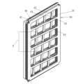
- FIG. 1 shows a perspective view of a humidifier element of a humidifier according to the present invention
- 2 shows a plan view of adjacent first and second hollow core sheets stacked in the humidifier element of FIG. 1
- FIG. 2 shows a perspective view of adjacent first and second hollow core sheets stacked in the humidifier element of FIG. 1
- FIG. 4 is a partial enlarged view of a portion P in FIG. 3.
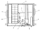
- FIG. 1 shows a schematic diagram of an air treatment device having a humidifier.
- Figure 1 shows a perspective view of a humidifier element 10 of a humidifier according to the present invention, which can be used, for example, in an air treatment device.
- the humidifier element 10 includes a fixing frame 11 provided at the top and bottom of the humidifier element 10, and a top plate 12 is provided at the top of the humidifier element 10, and a bottom plate 13 is provided at the bottom of the humidifier element 10.
- the fixing frame 11 fixes the humidifier core part 20, which is made up of multiple stacked core sheets, and can prevent the multiple core sheets constituting the humidifier core part 20 from coming apart.
- the top plate 12 and the bottom plate 13 serve to further fix the humidifier core part 20 from the top and bottom, and also seal the humidifier core part 20 from the top and bottom.
- side plates 14 are further provided on both sides of the humidifier core part 20, and the side plates 14 contribute to improving the strength and sealing of the humidifier element 10.
- the fixed frame 11 is provided at both the top and bottom of the humidification element 10, but the fixed frame 11 may be provided at either the top or bottom.
- the humidifying element 10 further includes a water inlet and a water outlet.
- the top plate 12 of the humidifying element 10 is provided with a first pipe portion 15 functioning as a water outlet.
- the bottom plate 13 of the humidifying element 10 is provided with a second pipe portion 16 capable of functioning as a water inlet, so that water can be injected into the humidifying core portion 20 of the humidifying element 10 through the second pipe portion 16. If the air in the humidifying core portion 20 can be discharged through the first pipe portion 15 during the injection of water from the second pipe portion 16 into the humidifying core portion 20, it is possible to ensure that the humidifying core portion 20 is filled with water.
- the water in the humidifying core portion 20 can be discharged through the first pipe portion 15, so that the generation of bacteria caused by the presence of water in the humidifying core portion 20 for a long period of time can be prevented.
- a water supply-outlet structure is simple in structure, and contributes to convenient water supply and drainage, and also has high operational efficiency for adding and draining water to the humidifying core.
- a port that functions not only as a water supply port but also as a water outlet port may be provided at the bottom of the humidifying element 10.
- the bottom port of the humidification element is provided with a second tube portion 16 that can be connected to a water pipe to allow water to be replenished to the humidification core portion.
- This type of water supply method quickly expels air from the humidifying core 20, maintains balance in the air pressure in the humidifying core 20, increases the contact area between the water and the moisture permeable membrane 50 (described in detail later), and contributes to improving humidification capacity. Furthermore, by supplying and draining water through the same port, it is possible to ensure balance in the internal pressure of the humidifying core 20 of the humidifying element 10 when refilling with water, and to prevent the moisture permeable membrane 50 from being deformed and even damaged by force, thereby contributing to extending the service life of the humidifying element 10. Furthermore, the moisture permeable membrane can be cleaned by draining water, preventing scaling.
- the humidifying element 10 further includes an air inlet 21 and an air outlet 22 connected to the humidifying core 20, and air enters the humidifying core 20 through the air inlet 21 and flows out through the air outlet 22.
- the air inlet 21 is actually a surface of the humidifying element 10 extending between the two side plates 14, which is open and faces the air inlet 3 (see FIG. 5) of the air treatment device 1 to form an opening whose range includes the entire front surface of the humidifying core 20, thereby allowing air to flow into the humidifying core.
- the air outlet 22 is a surface (the back surface in FIG.
- the cross section of the humidifier element 10 is preferably rectangular along the height direction of the humidifier element 10.
- the water inlet and/or water outlet are provided at positions corresponding to the long sides of the rectangle, and the air inlet 21 and the air outlet 22 are provided at positions corresponding to the short sides of the rectangle.
- the structure of the humidifying core 20 is described in more detail below.
- the humidifying core section 20 includes a plurality of first hollow core sheets 30, a plurality of second hollow core sheets 40, and a plurality of moisture-permeable membranes 50.
- the first hollow core sheets 30 and the second hollow core sheets 40 are alternately arranged, and the moisture-permeable membranes 50 are provided between adjacent first hollow core sheets 30 and second hollow core sheets 40.
- the first hollow core sheets 30, the second hollow core sheets 40, and the moisture-permeable membranes 50 are stacked to form the humidifying core section 20, and the above-mentioned fixed frame 11, the top plate 12, and/or the bottom plate 13 hold the stacked first hollow core sheets 30, the second hollow core sheets 40, and the moisture-permeable membranes 50 together to prevent them from coming apart.
- the first hollow core sheet 30 communicates with the intake port 21 and the exhaust port 22, and air can flow through the first hollow core sheet 30, where, as can be seen from Fig. 1, the passage in the first hollow core sheet 30 communicates with the intake port 21, so that air can flow into the first hollow core sheet 30 through the intake port 21. On the back side in Fig. 1, the passage in the first hollow core sheet 30 further communicates with the exhaust port 22, so that air can flow out.
- the second hollow core sheet 40 communicates with the first pipe portion 15 (water outlet) and the second pipe portion 16 (water supply port), and water can be stored in the second hollow core sheet 40.
- a space for storing water is formed in the base plate 13, the second pipe portion 16 communicates with the space in the base plate 13 to allow water to enter the space, and the passage in the second hollow core sheet 40 communicates with the space in the base plate 13 to allow water to flow into the second hollow core sheet 40.
- the first hollow core sheet 30 functions as an air side core sheet
- the second hollow core sheet 40 functions as a water side core sheet.
- the first hollow core sheet 30 and the second hollow core sheet 40 have a plurality of hollow passages. This allows the structure of these hollow passages to provide the first hollow core sheet 30 and the second hollow core sheet 40 with good waterproofing, corrosion resistance, and high strength.
- the first hollow core sheet 30 and the second hollow core sheet 40 can be manufactured from cardboard.
- At least one of the first hollow core sheet 30 and the second hollow core sheet 40 can be made of a synthetic resin material, for example, polypropylene (PP), polycarbonate, or the like.
- the second hollow core sheet 40 is made of a synthetic resin material such as polypropylene (PP) or polycarbonate, which has hydrophobic properties, and water in the second hollow core sheet 40 is less likely to be discharged by tension. Therefore, the second hollow core sheet 40 can preferably be subjected to a hydrophilic process, for example, a hydrophilic coating is applied to the second hollow core sheet 40 or a corona treatment is performed on the second hollow core sheet 40.
- the hydrophilic process can distribute water evenly on the surface of the second hollow core sheet 40, and facilitates the discharge of water by promoting the flow of water.
- the first hollow core sheet 30 includes a first frame portion 31 and at least one, preferably a plurality of first reinforcing ribs 32 extending between two opposing sides (e.g., two vertical sides in the figure) of the first frame portion 31.
- the first reinforcing rib 32 extends at an angle to the first frame portion 31, for example, as shown in the figure, forming a first angle ⁇ with the two vertical sides of the first frame portion 31.
- the second hollow core sheet 40 includes a second frame portion 41 and at least one, preferably a plurality of second ribs 42 extending between two opposing sides (e.g., two horizontal sides in the figure) of the second frame portion 41.
- the second rib 42 extends at an angle to the second frame portion 41, for example, as shown, making a second angle ⁇ with the two horizontal sides of the second frame portion 41.
- first reinforcing rib 32 and the second reinforcing rib 42 shown in the figure extend at an angle.
- the first reinforcing rib 32 may be provided at a right angle to the two vertical sides of the first frame portion 31, and the second reinforcing rib 42 may be provided at a right angle to the two horizontal sides of the second frame portion 41. This is also within the scope of the present application.
- a moisture-permeable membrane 50 is interposed between the first hollow core sheet 30 and the second hollow core sheet 40.
- the first hollow core sheet 30 and the second hollow core sheet 40 support the moisture-permeable membrane 50 therebetween, so that the moisture-permeable membrane 50 is less likely to deform during use.
- the moisture-permeable membrane 50 can achieve a sealed connection between the adjacent first hollow core sheet 30 and the second hollow core sheet 40 by a method such as heat pressing or bonding.
- the water contained in the second hollow core sheet 40 permeates the moisture-permeable membrane 50 and is taken away by the dry air passing through the first hollow core sheet 30, that is, the passing air can be humidified.
- the first reinforcing rib 32 of the first hollow core sheet 30 and the second reinforcing rib 42 of the second hollow core sheet 40 cross each other, which further improves the strength of the humidifying core section 20 and helps prevent the moisture permeable membrane 50 from deforming.
- the first reinforcing rib 32 and the second reinforcing rib 42 also cross each other to separate multiple moisture permeable regions 23.
- a moisture-permeable membrane 50 is attached to both sides of the second hollow core sheet 40.
- the moisture-permeable membrane 50 can be adhered to the second hollow core sheet 40 by an adhesive.
- the adhesive for adhering the second hollow core sheet 40 and the moisture-permeable membrane 50 may be at least one selected from a silicone resin adhesive, an epoxy resin adhesive, a urethane adhesive, an acrylic adhesive, a vinyl acetate adhesive, a vinyl chloride adhesive, a cyclic polyolefin resin adhesive, and a latex adhesive.
- the moisture permeable membrane 50 may be attached to the second hollow core sheet 40 by other methods besides adhesive, such as hot melt.
- first hollow core sheet 30 and the second hollow core sheet 40 are arranged so that the flow direction of the air flowing through the first hollow core sheet 30 (indicated by arrow A in FIG. 2) intersects with the flow direction of the water flowing through the second hollow core sheet 40 (indicated by arrow B in FIG. 2).
- the water flow pressure and air pressure received by the moisture permeable membrane 50 are in different directions, which reduces the pressure on the moisture permeable membrane 50, thereby contributing to reducing deformation.
- the first angle ⁇ is an acute angle, i.e., the first reinforcing rib 32 extends at an angle relative to the first frame portion 31.
- the first reinforcing rib 32 is formed with a first through hole 33 that leads to the corresponding moisture permeable region 23, which contributes to air flowing in and being distributed uniformly in the moisture permeable region 23.
- the second angle ⁇ is an acute angle, i.e., the second reinforcing rib 42 extends at an angle relative to the second frame portion 41, and the second reinforcing rib 42 includes a second through hole 43 that leads to the corresponding moisture permeable region 23, thereby contributing to water flowing in and being distributed evenly in the moisture permeable region 23.
- the pitch between two adjacent first reinforcing ribs 32 is preferably equal, and this pitch is a first pitch L1.
- the pitch between two adjacent second reinforcing ribs 42 is also preferably equal, and this pitch is a second pitch L2.
- the first pitch L1 is smaller than the second pitch L2.
- the inclination angle of the first reinforcing rib 32 and the second reinforcing rib 42 described above and the installation method of their first and second pitches L1, L2 contribute to maximizing the area of the moisture permeable region and further ensure the humidification efficiency of the humidification element.
- the first hollow core sheet 30 has a first thickness t1
- the second hollow core sheet 40 has a second thickness t2.
- the second thickness t2 is smaller than the first thickness t1, and for example, the second thickness t2 may be 1 to 2 mm, e.g., 1.8 mm, and the first thickness t1 may be 2 to 4 mm, e.g., 3 mm.
- the ratio of the second thickness t2 to the first thickness t1 is preferably selected from the range of 0.4 ⁇ t2/t1 ⁇ 1.
- t2/t1 is 0.6.
- the thickness of the first hollow core sheet 30 in the same humidifier element 10 may vary. It has been discovered that during use, the flow rate of air entering the air inlet 21 varies, with some locations having a higher flow rate and others having a lower flow rate. Specifically, the flow rate of the incoming air is relatively high in the portion of the air inlet 21 that is approximately aligned with the air inlet 3 of the air treatment device 1, and the flow rate of the air is relatively low in the surrounding portion. In response to this phenomenon, the humidifier element 10 may be provided to include a first portion corresponding to the portion of the air inlet 21 where the flow rate of the incoming air is high, and a second portion corresponding to the portion of the air inlet 21 where the flow rate of the incoming air is low.
- the thickness of the first hollow core sheet 30 in the first portion is made smaller than the thickness of the first hollow core sheet 30 in the second portion.
- the small thickness of the first hollow core sheet 30 provides a narrow air passage, which can slow down the air with a high flow rate when the flow resistance to the air increases. In this way, the air flow rate can be made approximately uniform throughout the humidifier element 10. Uniform air flow speed contributes to improving the humidification efficiency of the humidification element 10.
- the humidifier may optionally include a tank and an adjustment valve in addition to the humidification element 10.
- the tank can be connected to a water inlet, for example the second tube section 16 shown in the figure, and the adjustment valve is provided between the tank and the second tube section 16 and is used to adjust the amount of water input to the humidification core section 20.
- the tank may be connected to a city water supply or water may be added manually, all of which are within the scope of the present invention.
- the humidifier equipped with the humidification element 10 can be used in an air treatment device 1.
- the air treatment device 1 includes a housing 2 having an air intake 3 and an air exhaust 4, and an air passage 5 formed between the air intake 3 and the air exhaust 4.
- a water supply unit 6, a tank 7, and a humidification element 10 of the humidifier are sequentially provided in the air passage.
- the water supply unit 6 and the tank 7 are provided close to the side wall of the housing, so that the obstruction of the airflow caused by each unit of the humidifier can be minimized, and such a layout is advantageous for miniaturizing the air treatment device 1.
- the water supply unit 6 and the tank 7 are connected via a first water pipe 8, and the water supply unit 6 can be connected to a water source, such as city water, so that water can flow into the tank 7 via the water supply unit 6 and the first water pipe 8.
- a water source such as city water
- the tank 7 and the humidifying element 10 are connected via a second water pipe 9, and the above-mentioned adjustment valve, for example a three-way valve, is arranged in the second water pipe 9.
- the three-way valve can be switched between a first position and a second position.
- the tank 7 and the humidifying element 10 are connected, and at this time, the water in the tank 7 flows into the humidifying element 10 via the second water pipe 9 and the second tube section 16 of the humidifying element 10.
- the humidifying element 10 is in a draining state, and the water in the humidifying element 10 flows through the second tube section 16 to the three-way valve and is discharged from the water outlet end of the three-way valve.
- the humidifier may be provided outside the housing 2 and connected to the air flow path 5 in the housing 2.
- the humidifier can send humidified air into the room by utilizing the air treatment device's air blowing unit and air blowing path, and the humidifier can humidify the air sent into the room after the air treatment device processes the air (e.g., introduces fresh air, adjusts the air temperature, purifies the air), thereby further ensuring the comfort and cleanliness of the humidified air.
- the air treatment device processes the air (e.g., introduces fresh air, adjusts the air temperature, purifies the air), thereby further ensuring the comfort and cleanliness of the humidified air.
- Air treatment device 2 Housing 3: Air intake 4: Air exhaust 5: Air flow path 6: Water supply unit 7: Tank 8: First water pipe 9: Second water pipe 10: Humidification element 11: Fixed frame 12: Top plate 13: Base plate 14: Side plate 15: First pipe section 16: Second pipe section 20: Humidification core section 21: Air intake 22: Air exhaust 23: Moisture permeable area 30: First hollow core sheet 31: First frame section 32: First reinforcing rib 33: First through hole 40: Second hollow core sheet 41: Second frame section 42: Second reinforcing rib 43: Second through hole 50: Moisture permeable membrane ⁇ : First angle ⁇ : Second angle L1: First pitch L2: Second pitch t1 : First thickness t2 : Second thickness A : Air flow B : Water flow
Landscapes
- Engineering & Computer Science (AREA)
- Chemical & Material Sciences (AREA)
- Combustion & Propulsion (AREA)
- Mechanical Engineering (AREA)
- General Engineering & Computer Science (AREA)
- Air Humidification (AREA)
Abstract
吸気口と、排気口と、給水口と、加湿コア部とを有する加湿エレメントを含み、吸気口と排気口が加湿コア部の対向する両側に接続され、空気を加湿コア部に流入及び流出させるとともに、給水口を介して水を加湿コア部に注入することができる加湿器である。加湿コア部は、吸気口と排気口とに連通する複数の第1の中空コアシートと、給水口に連通する複数の第2の中空コアシートと、複数の透湿膜とを含む。透湿膜は隣接する第1の中空コアシートと第2の中空コアシートとの間に介在される。第1の中空コアシートの厚さt1は第2の中空コアシートの厚さt2よりも大きく、且つ、2つの厚さの比が0.4≦t2/t1<1である。この加湿器は、加湿性能を確保すると同時に、スケール形成のリスクを低減することができる。さらに、この加湿器を備えた空気処理装置に関する。
Description
本発明は、空気調和技術の分野に関し、具体的には、加湿器を備えた空気処理装置に関し、特にその加湿器に対する改良に関する。
空気調和機などの空気処理装置は、人々の生活作業環境に対する要求を満たすために、人々の生活にますます広く応用されている。多くの空気処理装置は、環境中の空気の湿度を調整するための加湿機能を有する。
現在、一般的な加湿器において、1つのタイプは、水を加湿器の頂部に搬送し、水を加湿器の頂部にかけ、水が重力の作用で加湿器の透湿膜に沿って下向きに浸透し、乾燥した風が透湿膜を通過するとき、水分が風によって奪われることによって、空気を加湿する役割を果たす。
もう一つのタイプの加湿器は、毛細管作用を有するフィルターエレメントを有し、該フィルターエレメントが水槽に浸漬され、毛細管作用により、水槽内の水が下から上への方向に沿ってフィルターエレメントの透湿膜に吸い上げられ、該フィルターエレメントに吹き付けられた乾燥風を加湿する。
従来のこれらの加湿器は、応用中にいくつかの問題が出て、例えば、透湿膜の吸水速度が遅く、収容できる吸水量も限られ、加湿器の加湿量の向上スペースが大きくない。そして、長期間にわたった加湿使用後には、透湿膜が変形しやすく、加湿器の加湿機能に影響を及ぼす。
これらの従来技術の加湿器の技術課題に対して、加湿エレメントを有する加湿器がさらに開発されており、該加湿エレメントは、水の通過と空気の通過にそれぞれ用いられる複数の中空コアシートを含み、水側コアシートと空気側コアシートと称されてもよく、水側コアシートと空気側コアシートとが互いに交互に積層され、隣接する水側コアシートと空気側コアシートとの間に透湿膜が挟まれることによって加湿エレメントが形成されている。
このようなタイプの加湿エレメントに対して、設計中、水側の幅、例えば水側コアシートの厚さを小さくすることが考えられるが、このようにコア部全体の幅が同じである条件では、空気層や水層の層数を増やして加湿能力を増加させることができ、そして、水層の厚さを小さくすると、加湿エレメントにおいて空気が通過する断面積が相対的に増加して通風抵抗を低減することができる。ただし、使用中に、水層が狭すぎると、水の表面張力により排水が困難になることを見出した。このように、加湿エレメントに対して排水したり、その中の水を入れ替えたりする必要がある場合、排水しきれないという問題があり、加湿エレメントに残留した水によってスケールなどが溜まりやすく、加湿エレメントにおける水通路を塞いでしまい、さらに加湿器の加湿性能に影響を及ぼす。
このため、加湿器の加湿性能をできるだけ向上させると同時に、加湿器の加湿エレメントにスケールが溜まることを防止するかは、依然としてさらに解決すべき課題である。
本発明は、上述した従来技術が存在する課題を解決するためになされたものである。本発明は、例えば、加湿効率の向上、通風抵抗の低減等の加湿器の加湿性能を向上させると同時に、スケールの溜まりを防止することができる、改良された加湿器及びそれを備えた空気処理装置を提供することを目的とする。
本発明に係る加湿器は、吸気口と、排気口と、給水口と、加湿コア部とを有する加湿エレメントを含み、吸気口と排気口が加湿コア部の対向する両側に接続され、空気を加湿コアシートに流入及び流出させるとともに、給水口を介して水を加湿コア部に注入することができる。加湿コア部は、吸気口と排気口とに連通する複数の第1の中空コア部と、給水口に連通するとともに、第1の中空コアシートと交互に配置される複数の第2の中空コアシートと、隣接する第1の中空コアシートと第2の中空コアシートとの間にそれぞれ介在される複数の透湿膜とを含む。第1の中空コアシートは、第1の厚さを有し、第2の中空コアシートは、第2の厚さを有し、第1の厚さが第2の厚さよりも大きく、且つ、第1の厚さをt1とし、第2の厚さをt2とすると、0.4≦t2/t1<1の条件を満たす。
上記構造の加湿器において、第1の中空コアシートは、吸気口と排気口に連通し、空気が流入するので空気側コアシートであり、第2の中空コアシートは、給水口に連通し、加湿のための水が流入するので水側コアシートである。研究により、第1の中空コアシートである空気側コアシートの厚さを第2の中空コアシートである水側コアシートの厚さよりも大きくし、且つ具体的に2つの厚さの比の範囲を0.4から1までの間に設定することによって、優れた加湿効率を実現でき、加湿エレメントを流れる空気に対する抵抗も小さくすると同時に、排水時に水の張力による水の残留が発生せず、これによって、加湿エレメントにスケールが形成されるリスクを低減させることが明らかである。
ここで、第1の中空コアシートと第2の中空コアシートとの少なくとも一方は、合成樹脂製である。具体的には、該合成樹脂は、ポリプロピレン及びポリカーボネートから選択される1種を含むことができる。
好ましくは、第2の中空コアシートは、親水プロセスによって処理され、例えば、第2の中空コアシートに親水コーティングを塗布したり、第2の中空コアシートをコロナ処理等したりすることができる。第1の中空コアシートと第2の中空コアシートは、ポリプロピレンやポリカーボネート等の合成樹脂で形成されている場合、疎水性を示し、水の表面張力により水の排出が阻害されるが、第2の中空コアシートを親水プロセス処理することによって、中空コアシートの表面に水を均一に分布させることができ、集まりにくくなり、水の排出に寄与する。
好ましくは、第2の中空コアシートの両側にそれぞれ透湿膜が貼り付けられている。透湿膜を第2の中空コアシートの両側に接着することによって、後続の加湿エレメントに対する加工処理を容易にすることができる。
好ましくは、接着剤を用いて透湿膜を第2の中空コアシートの両側に接着することができ、接着剤は、シリコン樹脂系接着剤、エポキシ樹脂系接着剤、ウレタン系接着剤、アクリル系接着剤、酢酸ビニル系接着剤、塩化ビニル系接着剤、環状ポリオレフィン樹脂系接着剤及びラテックス系接着剤から選ばれる少なくとも1種であってもよい。
その他、例えば、ホットメルト等の他の方式を用いて透湿膜を第2の中空コアシートに貼り付けてもよい。
好ましい構造において、各第1の中空コアシートは、第1の枠部と、第1の枠部の対向する2辺間で延在する少なくとも1つの第1の補強リブとを含み、各第2の中空コアシートは、第2の枠部と、第2の枠部の対向する2辺間で延在する少なくとも1つの第2の補強リブとを含み、第1の補強リブと第2の補強リブとが互いに交差するように、第1の中空コアシートと第2の中空コアシートとが配置されている。ここで、第1の補強リブと第2の補強リブは、第1の補強リブが第1の中空コアシートの対向する2辺に対して傾斜する場合、及び、第2の補強リブが第2の中空コアシートの対向する2辺に対して傾斜する場合のうちの少なくとも1つに設けられている。
第1と第2の補強リブの該傾斜設置は、中空コアシートにおける空気と水流の均一な分布を容易にすることによって、加湿効率を向上させることができる。
好ましくは、加湿エレメントは、吸気口における空気の流速が大きい部分に対応する第1の部分と、吸気口における空気の流速が小さい部分に対応する第2の部分とを含み、ここで、第1の部分における第1の中空コアシートの厚さが第2の部分における第1の中空コアシートの厚さよりも小さい。
さらに、上記のような加湿器を備えた空気処理装置に関する。
好ましくは、空気処理装置は、吸風口と、排風口と、吸風口と排風口との間で延在する送風経路とが設けられているハウジングを含み、ここで、加湿器が送風経路に位置するか、又は送風経路に連通する。
好ましくは、加湿エレメントと吸風口との間の領域は、送風経路に垂直な方向における断面が吸風口に対向する第1の領域と、第1の領域に隣接する第2の領域とを含み、ここで、加湿エレメントは、第1の部分と第2の部分とを含み、加湿エレメントがハウジングに取り付けられたとき、第1の部分が第1の領域に対応し、第2の部分が第2の領域に対応し、第1の部分における第1の中空コアシートが第3の厚さを有し、第2の部分における第1の中空コアシートが第4の厚さを有し、第3の厚さが第4の厚さよりも小さい。
このような異なる第1の中空コアシートの厚さを設けることによって、空気の流速を加湿エレメント全体にわたってほぼ均一にすることができ、均一な空気の流速は、加湿エレメントの加湿効率を向上させることに寄与する。
本発明の具体的な実施形態は、図面に示される構造からより明らかになり、ここで、各図面は以下の通りである。
本発明を容易に理解するために、以下、図面を参照しながら本発明に係る空気処理装置における加湿器の具体的な実施形態を詳細に説明する。図面に示されるのは、本発明の好ましい実施例に過ぎず、本発明の範囲を限定するものとして理解されるべきではない。当業者は、図面に示す実施例に基づいて本発明に対して各種の明らかな補正、変形、同等置換を行うことができ、矛盾しない限り、以下に説明される異なる実施例における構成要件を互いに任意に組み合わせることができ、これらはいずれも本発明の範囲内にある。
以下の本発明に対する具体的な説明において、使用される「上」、「下」、「頂」、「底」などの用語は、図面に示す加湿器の使用状態を基準とする。
図1は、本発明に係る加湿器の加湿エレメント10の斜視図を示しており、該加湿エレメント10は、例えば空気処理装置に用いられることができる。
加湿エレメント10は、加湿エレメント10の頂部と底部にそれぞれ設けられる固定枠11を含み、且つ、加湿エレメント10の頂部に天盤12が設けられており、加湿エレメント10の底部に底盤13が設けられている。固定枠11は、複数のコアシートが積層された加湿コア部20を固定し、加湿コア部20を構成する複数のコアシートがばらけることを防止することができる。天盤12と底盤13は、加湿コア部20を頂部と底部とからさらに固定する役割を果たすとともに、加湿コア部20を頂部と底部とから封止する。好ましくは、加湿コア部20の両側にそれぞれ側板14がさらに設けられており、側板14により加湿エレメント10の強度及び封止性を向上させることに寄与する。
図に示す構造では、加湿エレメント10の頂部にも底部にも固定枠11が設けられているが、頂部及び底部の一方に固定枠11を設けてもよい。
加湿エレメント10は、給水口と出水口とをさらに含む。例えば、図示の例示的な構造では、加湿エレメント10の天盤12に、出水口として機能する第1の管部15が設けられている。また、加湿エレメント10の底盤13には、給水口として機能可能な第2の管部16が設けられていることによって、該第2の管部16を介して加湿エレメント10の加湿コア部20に水を注入することができる。第2の管部16から加湿コア部20への注水中に、加湿コア部20における空気が第1の管部15を通って排出されることができると、加湿コア部20に水を満たすように注水することが確保されることができる。加湿を停止する時、第1の管部15を介して加湿コア部20における水を排出することができることによって、加湿コア部20内に長期間にわたって水が存在することに起因する菌の発生を防止することができる。このような給水-出水は、構造が簡単であり、給水と排水を便利に行うことに寄与することに加え、加湿コア部に対して水を加えたり排水したりする操作効率も高い。もちろん、加湿エレメント10の底部に、給水口のみならず出水口としても機能するポートを1つ設けてもよい。加湿を行う必要がある場合、該ポートを介して底部から上方へ水を加湿コア部20に補充すると同時に、水のために空間を空けるために、頂部のポート(例えば第1の管部15)で空気を排出するためのみに用いられる。
図示するように、加湿エレメントの底部ポートには第2の管部16が設けられており、該第2の管部16は、加湿コア部に水を補充できるように水管に接続されることができる。
このような給水方式は、加湿コア部20における空気を迅速に追い出し、加湿コア部20における気圧のバランスを保ち、水と透湿膜50(詳細は後述)との間の接触面積を増加させ、さらに加湿能力を向上させることに寄与する。なお、同一のポートを介して給水と排水を行うことによって、水補充時の加湿エレメント10の加湿コア部20の内部圧力の均衡を確保し、透湿膜50が力を受けて変形し、ひいては破損することを防止することができ、加湿エレメント10の使用寿命を延すことに寄与する。そして、排水によって透湿膜を洗浄し、スケーリングを防止することができる。
加湿エレメント10は、加湿コア部20に接続された吸気口21と排気口22とをさらに含み、空気は、吸気口21から加湿コア部20に入り、排気口22から流出する。図1に示す構造において、吸気口21は、実際には、2つの側板14の間に延在する加湿エレメント10の面であり、該面が開放され、空気処理装置1の吸風口3(図5を参照)に対向して、範囲が加湿コア部20の正面全体を含む開口を形成することによって、加湿コア部内に空気が流入することを許容する。これに対応して、排気口22は、吸気口21に対向して位置決めされる面(図1における裏面)であり、該面も開放されており、範囲が加湿コア部20の裏面全体を含む開口を形成することによって、空気の流出を許容する。空気が加湿コア部20を流れる過程で、加湿コア部20における水と接触することによって、加湿される。図1に示すように、好ましくは、加湿エレメント10の断面は、加湿エレメント10の高さ方向に沿って矩形状を呈する。そして、給水口及び/又は出水口は、該矩形の長辺に対応する位置に設けられており、吸気口21と排気口22は、該矩形の短辺に対応する位置に設けられている。このように設定することによって、加湿エレメント10における貯水量を高めることができ、さらに加湿量が等しい場合には加湿エレメント10の体積を小さくすることができ、これによって、加湿エレメント10の小型化に寄与する。
以下、加湿コア部20の構造をさらに詳細に説明する。
加湿コア部20は、複数の第1の中空コアシート30と、複数の第2の中空コアシート40と、複数の透湿膜50とを含む。第1の中空コアシート30と第2の中空コアシート40とは、交互に配置され、隣接する第1の中空コアシート30と第2の中空コアシート40との間に透湿膜50が設けられている。第1の中空コアシート30、第2の中空コアシート40及び透湿膜50が積層されて加湿コア部20が形成され、上述した固定枠11、天盤12及び/又は底盤13は、積層された第1の中空コアシート30、第2の中空コアシート40及び透湿膜50を一緒に保持し、ばらけることを防止する。
第1の中空コアシート30は、吸気口21と排気口22とに連通し、空気は、第1の中空コアシート30を流れることができ、ここで、図1から分かるように、第1の中空コアシート30における通路は、吸気口21に連通することによって、空気は、吸気口21を介して第1の中空コアシート30に流入することができる。図1における裏面において、第1の中空コアシート30の通路は、さらに排気口22に連通することによって、空気が流出できる。第2の中空コアシート40は、第1の管部15(出水口)と第2の管部16(給水口)とに連通し、水は第2の中空コアシート40に収容されることができる。具体的には、底盤13には、水を収容するための空間が形成されており、第2の管部16は、水が該空間に入ることを許容するように底盤13における該空間に連通し、第2の中空コアシート40における通路は、水が第2の中空コアシート40に流入することを許容するように底盤13における空間に連通する。これによりわかるように、第1の中空コアシート30は空気側コアシートとして機能し、第2の中空コアシート40は水側コアシートとして機能する。
第1の中空コアシート30は、吸気口21と排気口22とに連通し、空気は、第1の中空コアシート30を流れることができ、ここで、図1から分かるように、第1の中空コアシート30における通路は、吸気口21に連通することによって、空気は、吸気口21を介して第1の中空コアシート30に流入することができる。図1における裏面において、第1の中空コアシート30の通路は、さらに排気口22に連通することによって、空気が流出できる。第2の中空コアシート40は、第1の管部15(出水口)と第2の管部16(給水口)とに連通し、水は第2の中空コアシート40に収容されることができる。具体的には、底盤13には、水を収容するための空間が形成されており、第2の管部16は、水が該空間に入ることを許容するように底盤13における該空間に連通し、第2の中空コアシート40における通路は、水が第2の中空コアシート40に流入することを許容するように底盤13における空間に連通する。これによりわかるように、第1の中空コアシート30は空気側コアシートとして機能し、第2の中空コアシート40は水側コアシートとして機能する。
好ましくは、第1の中空コアシート30と第2の中空コアシート40は、複数の中空通路を有する。これにより、これらの中空通路の構造によって、第1の中空コアシート30と第2の中空コアシート40に良好な防水、耐腐食性及び高い強度を持たせることができる。例えば、第1の中空コアシート30と第2の中空コアシート40は、段ボールで製造されることができる。
第1の中空コアシート30と第2の中空コアシート40の少なくとも一方は、合成樹脂材料によって製造されることができ、例えば、ポリプロピレン(PP)、ポリカーボネート等の材料の1種によって製造されることができる。第2の中空コアシート40は、ポリプロピレン(PP)やポリカーボネートなどのような合成樹脂材料が疎水性を有しており、第2の中空コアシート40における水が張力によって排出されにくくなる。そのため、好ましくは、第2の中空コアシート40を親水プロセス処理することができ、例えば、第2の中空コアシート40に親水コーティングを塗布したり、第2の中空コアシート40に対してコロナ処理を行ったりする。親水プロセス処理により、水を第2の中空コアシート40の表面に均一に分布させることができ、水の流れを促進させることによって、水の排出を容易にする。
図2は、積層された第1の中空コアシート30と第2の中空コアシート40の例示的な構造の概略平面図を示し、図3は、積層された第1の中空コアシート30と第2の中空コアシートの斜視図を示し、図4は、図3におけるP部の部分拡大図である。第1の中空コアシート30は、第1の枠部31と、第1の枠部31の対向する2辺(例えば図における2つの垂直辺)の間に延在する少なくとも1つの、好ましくは複数の第1の補強リブ32とを含む。好ましくは、第1の補強リブ32は、第1の枠部31に対して角度をなして延在し、例えば、図に示すように、第1の枠部31の2つの垂直辺に対して第1の角度αをなす。
第2の中空コアシート40は、第2の枠部41と、第2の枠部41の対向する2辺(例えば、図における2つの水平辺)の間に延在する少なくとも1つの、好ましくは、複数の第2のリブ42とを含む。好ましくは、第2リブ42は、第2の枠部41に対して角度をなして延在し、例えば、図示するように、第2の枠部41の2つの水平辺に対して第2の角度βをなす。
図に示す第1の補強リブ32及び第2の補強リブ42が傾斜して延在する場合が好ましい。第1の補強リブ32を第1の枠部31の2つの垂直辺に直角をなすように設け、第2の補強リブ42を第2の枠部41の2つの水平辺に直角をなすように設けてもよい。これも本願の範囲内である。
第1の中空コアシート30と第2の中空コアシート40との間には透湿膜50が介在されており、図4に示すように、第1の中空コアシート30と第2の中空コアシート40とは、それらの間の透湿膜50を支持する役割を果たし、これにより、透湿膜50は使用中に変形しにくい。ここで、具体的には、透湿膜50は、熱プレス、接着などの方式により、隣接する第1の中空コアシート30と第2の中空コアシート40との封止接続を実現することができる。加湿中、第2の中空コアシート40に収容された水は、透湿膜50を透過するとともに、第1の中空コアシート30を通過する乾燥空気によって奪われ、すなわち通過する空気を加湿することができる。
第1の中空コアシート30と第2の中空コアシート40とが積層されたときに、第1の中空コアシート30の第1の補強リブ32と第2の中空コアシート40の第2の補強リブ42とが互いに交差することによって、加湿コア部20の強度がさらに向上させ、透湿膜50が変形することを防止ことに寄与する。また、第1の補強リブ32と第2の補強リブ42とは、互いに交差して複数の透湿領域23も仕切られている。
好ましくは、第2の中空コアシート40の両側には、透湿膜50が貼り付けられている。例えば、透湿膜50を接着剤により第2の中空コアシート40に接着することができる。第2の中空コアシート40と透湿膜50とを接着する接着剤は、シリコン樹脂系接着剤、エポキシ樹脂系接着剤、ウレタン系接着剤、アクリル系接着剤、酢酸ビニル系接着剤、塩化ビニル系接着剤、環状ポリオレフィン樹脂系接着剤及びラテックス系接着剤から選択される少なくとも1種であってもよい。
透湿膜50は、接着剤の他、例えば、ホットメルト等の他の方式により第2の中空コアシート40に貼り付けられてもよい。
さらに、第1の中空コアシート30と第2の中空コアシート40は、第1の中空コアシート30を流れる空気の流れ方向(図2における矢印Aに示すもの)と、第2の中空コアシート40を流れる水流の流れ方向(図2における矢印Bに示すもの)とが交差するように設けられている。このように、透湿膜50の受ける水流の圧力と空気の圧力とは方向が異なることによって、透湿膜50に対する圧力が軽減され、これによって、変形の低減に寄与することができる。
好ましくは、第1の角度αが鋭角であり、即ち、第1の補強リブ32は第1の枠部31に対して傾斜して延在している。このように、第1の補強リブ32には、対応する透湿領域23に通じる第1の貫通孔33が形成されており、これによって、空気が該透湿領域23に均一に流入して分布することに寄与する。
同様に、第2の角度βが鋭角であることが好ましく、即ち、第2の補強リブ42は、第2の枠部41に対して傾斜して延在していることによって、第2の補強リブ42には、対応する透湿領域23に通じる第2の貫通孔43が含まれることによって、水が該透湿領域23に均一に流入して分布することに寄与する。
図2に戻って見えるように、第1の中空コアシート30において、隣接する2つの第1の補強リブ32の間のピッチは好ましくは等しく、該ピッチは第1のピッチL1である。第2の中空コアシート40において、隣接する2つの第2の補強リブ42の間のピッチも好ましくは等しく、該ピッチは第2のピッチL2である。好ましくは、該第1のピッチL1は、第2のピッチL2よりも小さい。隣接する第1の補強リブ32間の第1のピッチL1を、隣接する第2の補強リブ42間の第2のピッチL2よりも小さくすることによって、水圧の作用によって透湿膜50が過大に変形して空気側の通路が狭くなることがなく、これによって、気流をよりスムーズにすることができる。
上述の第1の補強リブ32と第2の補強リブ42の傾斜角度及びそれらの第1と第2のピッチL1、L2の設置方式は、透湿領域の面積を最大化することに寄与するとともに、さらに加湿エレメントの加湿効率を確保することができる。
図4から明らかなように、第1の中空コアシート30は第1の厚さt1を有し、第2の中空コアシート40は第2の厚さt2を有する。ここで、第2の厚さt2は第1の厚さt1よりも小さく、例えば、第2の厚さt2は1~2mm、例えば1.8mmであってもよく、第1の厚さt1は2~4mm、例えば3mmであってもよい。
さらに、第2の厚さt2と第1の厚さt1との比は、好ましくは0.4≦t2/t1<1という範囲から選択される。例えば、第2の厚さt2が1.8mmであり、第1の厚さt1が3mmである場合、t2/t1は0.6である。
なお、同一の加湿エレメント10における第1の中空コアシート30の厚さが変化してもよい。使用中、吸気口21に入る空気の流速が異なり、ある場所での流速が大きく、ある場所での流速が小さいことが発見されている。具体的には、吸気口21における空気処理装置1の吸風口3と略位置合わせする部分では流入する空気の流速が比較的大きく、その周囲の部分では空気の流速が比較的小さい。この現象に対して、吸気口21における流入する空気の流速が大きい部分に対応する第1の部分と、吸気口21における流入する空気の流速が小さい部分に対応する第2の部分とを含むように加湿エレメント10を設けてもよい。また、第1の部分における第1の中空コアシート30の厚さを、第2の部分における第1の中空コアシート30の厚さよりも小さくする。第1の中空コアシート30の小さい厚さは、狭い空気通路を提供することによって、空気に対する流動抵抗が大きくなると、流速の速い空気を減速させることができる。このようにして、加湿エレメント10全体で空気の流速をほぼ均一にすることができる。空気流速の均一化は、加湿エレメント10の加湿効率を向上させることに寄与する。
さらに、加湿器は、加湿エレメント10に加えて、選択可能にタンクと、調整弁とを含んでもよい。タンクは、給水口、例えば図に示す第2の管部16に接続されることができるとともに、調整弁は、タンクと第2の管部16との間に設けられ、加湿コア部20に入力される水の量を調整するために用いられる。
代替的又は付加的な場合として、タンクは、市水路に接続されてもよく、又は、手動で水を加えてもよい。これらはいずれも本発明の範囲内である。
上記加湿エレメント10を備えた加湿器は、具体的には、空気処理装置1に用いられることができる。図5に示すように、該空気処理装置1は、吸風口3と排風口4とが設けられ吸風口3と排風口4の間に送風経路5が形成されているハウジング2を含む。該送風経路には、加湿器の給水ユニット6、タンク7及び加湿エレメント10が順次設けられている。好ましくは、給水ユニット6とタンク7がハウジングの側壁に近接して設けられると、加湿器の各ユニットによる気流に対する阻害を最小にすることができ、このようなレイアウトにより空気処理装置1を小型化することに有利である。
給水ユニット6とタンク7とは、第1の水管8を介して連通されるとともに、給水ユニット6は、例えば、市水のような水源に接続されることができることによって、水は、給水ユニット6及び第1の水管8を介してタンク7に流入することができる。
タンク7と加湿エレメント10とは、第2の水管9を介して接続されており、該第2の水管9には、例えば三方弁である上述した調整弁が配置されている。三方弁は、第1の位置と第2の位置との間で切り替えることができる。ここで、第1の位置において、タンク7と加湿エレメント10とが連通し、このとき、タンク7内の水は、第2の水管9及び加湿エレメント10の第2の管部16を介して加湿エレメント10に流入する。第2の位置において、加湿エレメント10が排水状態にあり、加湿エレメント10における水は、第2の管部16を通って三方弁に流れるとともに、三方弁の出水端から排出される。
他の代替的な実施形態において、加湿器をハウジング2の外側に設けるとともに、ハウジング2における送風経路5に接続してもよい。
このようにして、加湿器は、空気処理装置の送風ユニット、送風経路を利用して室内に加湿された空気を送ることができ、そして、加湿器は、空気処理装置が室内に送り込まれる空気を処理(例えば、新気導入、空気温度調整、空気清浄)した後で加湿することができ、加湿された空気の快適さ、清浄度をより確保することができる。
1 :空気処理装置
2 :ハウジング
3 :吸風口
4 :排風口
5 :送風経路
6 :給水ユニット
7 :タンク
8 :第1の水管
9 :第2の水管
10 :加湿エレメント
11 :固定枠
12 :天盤
13 :底盤
14 :側板
15 :第1の管部
16 :第2の管部
20 :加湿コア部
21 :吸気口
22 :排気口
23 :透湿領域
30 :第1の中空コアシート
31 :第1の枠部
32 :第1の補強リブ
33 :第1の貫通孔
40 :第2の中空コアシート
41 :第2の枠部
42 :第2の補強リブ
43 :第2の貫通孔
50 :透湿膜
α :第1の角度
β :第2の角度
L1 :第1のピッチ
L2 :第2のピッチ
t1 :第1の厚さ
t2 :第2の厚さ
A :空気の流れ
B :水流の流れ
2 :ハウジング
3 :吸風口
4 :排風口
5 :送風経路
6 :給水ユニット
7 :タンク
8 :第1の水管
9 :第2の水管
10 :加湿エレメント
11 :固定枠
12 :天盤
13 :底盤
14 :側板
15 :第1の管部
16 :第2の管部
20 :加湿コア部
21 :吸気口
22 :排気口
23 :透湿領域
30 :第1の中空コアシート
31 :第1の枠部
32 :第1の補強リブ
33 :第1の貫通孔
40 :第2の中空コアシート
41 :第2の枠部
42 :第2の補強リブ
43 :第2の貫通孔
50 :透湿膜
α :第1の角度
β :第2の角度
L1 :第1のピッチ
L2 :第2のピッチ
t1 :第1の厚さ
t2 :第2の厚さ
A :空気の流れ
B :水流の流れ
Claims (10)
- 吸気口と、排気口と、給水口と、加湿コア部とを有する加湿エレメントを含み、前記吸気口と前記排気口が前記加湿コア部の対向する両側に接続され、空気を前記加湿コア部に流入及び流出させるとともに、前記給水口を介して水を前記加湿コア部に注入することができる加湿器において、
前記加湿コア部は、
前記吸気口と前記排気口とに連通する複数の第1の中空コアシートと、
前記給水口に連通するとともに、前記第1の中空コアシートと交互に配置される複数の第2の中空コアシートと、
隣接する前記第1の中空コアシートと前記第2の中空コアシートとの間にそれぞれ介在される複数の透湿膜とを含み、
前記第1の中空コアシートは、第1の厚さを有し、前記第2の中空コアシートは、第2の厚さを有し、前記第1の厚さが前記第2の厚さよりも大きく、且つ、前記第1の厚さをt1とし、前記第2の厚さをt2とすると、0.4≦t2/t1<1の条件を満たす
ことを特徴とする加湿器。 - 前記第1の中空コアシートと前記第2の中空コアシートとの少なくとも一方は、合成樹脂製である
ことを特徴とする請求項1に記載の加湿器。 - 合成樹脂は、ポリプロピレン及びポリカーボネートから選択される1種を含む
ことを特徴とする請求項2に記載の加湿器。 - 前記第2の中空コアシートは、親水プロセスによって処理された
ことを特徴とする請求項2又は3に記載の加湿器。 - 前記第2の中空コアシートの両側にそれぞれ前記透湿膜が貼り付けられている
ことを特徴とする請求項1に記載の加湿器。 - 前記透湿膜は、接着剤により前記第2の中空コアシートに接着され、
前記接着剤は、シリコン樹脂系接着剤、エポキシ樹脂系接着剤、ウレタン系接着剤、アクリル系接着剤、酢酸ビニル系接着剤、塩化ビニル系接着剤、環状ポリオレフィン樹脂系接着剤及びラテックス系接着剤から選ばれる少なくとも1種である
ことを特徴とする請求項5に記載の加湿器。 - 各前記第1の中空コアシートは、第1の枠部と、前記第1の枠部の対向する2辺間で延在する少なくとも1つの第1の補強リブとを含み、各前記第2の中空コアシートは、第2の枠部と、前記第2の枠部の対向する2辺間で延在する少なくとも1つの第2の補強リブとを含み、前記第1の補強リブと前記第2の補強リブとが互いに交差するように、前記第1の中空コアシートと前記第2の中空コアシートとが配置されており、
且つ、前記第1の補強リブと前記第2の補強リブは、前記第1の補強リブが前記第1の中空コアシートの前記対向する2辺に対して傾斜する場合、及び、前記第2の補強リブが前記第2の中空コアシートの前記対向する2辺に対して傾斜する場合のうちの少なくとも1つに設けられている
ことを特徴とする請求項1に記載の加湿器。 - 請求項1~7のいずれか1項に記載の加湿器を含む
ことを特徴とする空気処理装置。 - 吸風口と、排風口と、前記吸風口と前記排風口との間で延在する送風経路とが設けられているハウジングを含み、前記加湿器が前記送風経路に位置するか、又は前記送風経路に連通する
ことを特徴とする請求項8に記載の空気処理装置。 - 前記加湿エレメントと前記吸風口との間の領域は、前記送風経路に垂直な方向における断面が前記吸風口に対向する第1の領域と、前記第1の領域に隣接する第2の領域とを含み、前記加湿エレメントは、第1の部分と第2の部分とを含み、前記加湿エレメントが前記ハウジングに取り付けられたとき、前記第1の部分が前記第1の領域に対応し、前記第2の部分が前記第2の領域に対応し、前記第1の部分における前記第1の中空コアシートが第3の厚さを有し、前記第2の部分における前記第1の中空コアシートが第4の厚さを有し、前記第3の厚さが前記第4の厚さよりも小さい
ことを特徴とする請求項9に記載の空気処理装置。
Applications Claiming Priority (2)
| Application Number | Priority Date | Filing Date | Title |
|---|---|---|---|
| CN202310807174.8 | 2023-06-30 | ||
| CN202310807174.8A CN119222663A (zh) | 2023-06-30 | 2023-06-30 | 加湿器及包括该加湿器的空气处理设备 |
Publications (1)
| Publication Number | Publication Date |
|---|---|
| WO2025005180A1 true WO2025005180A1 (ja) | 2025-01-02 |
Family
ID=93939183
Family Applications (1)
| Application Number | Title | Priority Date | Filing Date |
|---|---|---|---|
| PCT/JP2024/023327 Ceased WO2025005180A1 (ja) | 2023-06-30 | 2024-06-27 | 加湿器及びそれを備えた空気処理装置 |
Country Status (2)
| Country | Link |
|---|---|
| CN (1) | CN119222663A (ja) |
| WO (1) | WO2025005180A1 (ja) |
Citations (4)
| Publication number | Priority date | Publication date | Assignee | Title |
|---|---|---|---|---|
| JPH08128682A (ja) * | 1994-09-08 | 1996-05-21 | Japan Gore Tex Inc | 加湿ユニット |
| JP2003176939A (ja) * | 2001-12-12 | 2003-06-27 | Mitsubishi Electric Corp | 加湿シート、加湿エレメント及び加湿装置 |
| JP2011167618A (ja) * | 2010-02-17 | 2011-09-01 | Nihon Gore Kk | 積層部材の製造方法 |
| JP2019027706A (ja) * | 2017-07-31 | 2019-02-21 | 株式会社コア電子 | 加湿エレメント及び該加湿エレメントを用いた加湿機装置 |
-
2023
- 2023-06-30 CN CN202310807174.8A patent/CN119222663A/zh active Pending
-
2024
- 2024-06-27 WO PCT/JP2024/023327 patent/WO2025005180A1/ja not_active Ceased
Patent Citations (4)
| Publication number | Priority date | Publication date | Assignee | Title |
|---|---|---|---|---|
| JPH08128682A (ja) * | 1994-09-08 | 1996-05-21 | Japan Gore Tex Inc | 加湿ユニット |
| JP2003176939A (ja) * | 2001-12-12 | 2003-06-27 | Mitsubishi Electric Corp | 加湿シート、加湿エレメント及び加湿装置 |
| JP2011167618A (ja) * | 2010-02-17 | 2011-09-01 | Nihon Gore Kk | 積層部材の製造方法 |
| JP2019027706A (ja) * | 2017-07-31 | 2019-02-21 | 株式会社コア電子 | 加湿エレメント及び該加湿エレメントを用いた加湿機装置 |
Also Published As
| Publication number | Publication date |
|---|---|
| CN119222663A (zh) | 2024-12-31 |
Similar Documents
| Publication | Publication Date | Title |
|---|---|---|
| US6800118B2 (en) | Gas/liquid separation devices | |
| US7309062B2 (en) | Fixed wet type dehumidification and energy recovery device | |
| CN101266109A (zh) | 全热交换器及其制造方法 | |
| CN105765309A (zh) | 用于湍流式耐腐蚀换热器的方法和系统 | |
| EP1291585B1 (en) | Gas/liquid separation devices | |
| JP4432518B2 (ja) | 燃料電池システム | |
| WO2025005180A1 (ja) | 加湿器及びそれを備えた空気処理装置 | |
| US6189869B1 (en) | Wick system for a humidifier | |
| JP2007147117A (ja) | 間接気化冷却エレメント、空調装置及び建物 | |
| CN220417569U (zh) | 加湿器及包括该加湿器的空气处理设备 | |
| JPH04320743A (ja) | 自然蒸発式加湿器 | |
| JP3305546B2 (ja) | 滴下方式の自然蒸発式加湿器 | |
| CN220417523U (zh) | 加湿器和空气处理设备 | |
| CN217031467U (zh) | 加湿组件及电暖器 | |
| JP7186648B2 (ja) | 加湿素子、加湿装置、換気装置及び空気調和機 | |
| JPH068420Y2 (ja) | 加湿器 | |
| JPH058340B2 (ja) | ||
| JP7236877B2 (ja) | 加湿装置、換気装置及び空気調和機 | |
| CN223360794U (zh) | 具有旁通通道的加湿器和具有加湿器的新风系统 | |
| JP7236872B2 (ja) | 加湿素子、加湿装置、空気調和機および換気装置 | |
| JPH08178375A (ja) | 加湿装置 | |
| CN220689252U (zh) | 加湿器及空气处理设备 | |
| CN221098822U (zh) | 空调器室内机的加湿装置及空调器室内机 | |
| CN117836564A (zh) | 加湿元件、加湿装置、换气装置以及空调机 | |
| JP7462003B1 (ja) | 加湿エレメントおよびこれを備える空気調和装置 |
Legal Events
| Date | Code | Title | Description |
|---|---|---|---|
| 121 | Ep: the epo has been informed by wipo that ep was designated in this application |
Ref document number: 24832039 Country of ref document: EP Kind code of ref document: A1 |
|
| NENP | Non-entry into the national phase |
Ref country code: DE |