WO2025005100A1 - 接続構造 - Google Patents
接続構造 Download PDFInfo
- Publication number
- WO2025005100A1 WO2025005100A1 PCT/JP2024/023073 JP2024023073W WO2025005100A1 WO 2025005100 A1 WO2025005100 A1 WO 2025005100A1 JP 2024023073 W JP2024023073 W JP 2024023073W WO 2025005100 A1 WO2025005100 A1 WO 2025005100A1
- Authority
- WO
- WIPO (PCT)
- Prior art keywords
- guide rail
- elastic claw
- claw
- main body
- carrier plate
- Prior art date
- Legal status (The legal status is an assumption and is not a legal conclusion. Google has not performed a legal analysis and makes no representation as to the accuracy of the status listed.)
- Ceased
Links
Images





Classifications
-
- B—PERFORMING OPERATIONS; TRANSPORTING
- B60—VEHICLES IN GENERAL
- B60J—WINDOWS, WINDSCREENS, NON-FIXED ROOFS, DOORS, OR SIMILAR DEVICES FOR VEHICLES; REMOVABLE EXTERNAL PROTECTIVE COVERINGS SPECIALLY ADAPTED FOR VEHICLES
- B60J1/00—Windows; Windscreens; Accessories therefor
- B60J1/08—Windows; Windscreens; Accessories therefor arranged at vehicle sides
- B60J1/12—Windows; Windscreens; Accessories therefor arranged at vehicle sides adjustable
- B60J1/16—Windows; Windscreens; Accessories therefor arranged at vehicle sides adjustable slidable
- B60J1/17—Windows; Windscreens; Accessories therefor arranged at vehicle sides adjustable slidable vertically
-
- E—FIXED CONSTRUCTIONS
- E05—LOCKS; KEYS; WINDOW OR DOOR FITTINGS; SAFES
- E05F—DEVICES FOR MOVING WINGS INTO OPEN OR CLOSED POSITION; CHECKS FOR WINGS; WING FITTINGS NOT OTHERWISE PROVIDED FOR, CONCERNED WITH THE FUNCTIONING OF THE WING
- E05F11/00—Man-operated mechanisms for operating wings, including those which also operate the fastening
- E05F11/38—Man-operated mechanisms for operating wings, including those which also operate the fastening for sliding windows, e.g. vehicle windows, to be opened or closed by vertical movement
-
- E—FIXED CONSTRUCTIONS
- E05—LOCKS; KEYS; WINDOW OR DOOR FITTINGS; SAFES
- E05F—DEVICES FOR MOVING WINGS INTO OPEN OR CLOSED POSITION; CHECKS FOR WINGS; WING FITTINGS NOT OTHERWISE PROVIDED FOR, CONCERNED WITH THE FUNCTIONING OF THE WING
- E05F11/00—Man-operated mechanisms for operating wings, including those which also operate the fastening
- E05F11/38—Man-operated mechanisms for operating wings, including those which also operate the fastening for sliding windows, e.g. vehicle windows, to be opened or closed by vertical movement
- E05F11/48—Man-operated mechanisms for operating wings, including those which also operate the fastening for sliding windows, e.g. vehicle windows, to be opened or closed by vertical movement operated by cords or chains or other flexible elongated pulling elements, e.g. tapes
-
- E—FIXED CONSTRUCTIONS
- E05—LOCKS; KEYS; WINDOW OR DOOR FITTINGS; SAFES
- E05F—DEVICES FOR MOVING WINGS INTO OPEN OR CLOSED POSITION; CHECKS FOR WINGS; WING FITTINGS NOT OTHERWISE PROVIDED FOR, CONCERNED WITH THE FUNCTIONING OF THE WING
- E05F15/00—Power-operated mechanisms for wings
- E05F15/60—Power-operated mechanisms for wings using electrical actuators
- E05F15/603—Power-operated mechanisms for wings using electrical actuators using rotary electromotors
- E05F15/665—Power-operated mechanisms for wings using electrical actuators using rotary electromotors for vertically-sliding wings
- E05F15/689—Power-operated mechanisms for wings using electrical actuators using rotary electromotors for vertically-sliding wings specially adapted for vehicle windows
Definitions
- the present invention relates to a connection structure.
- a window regulator that raises and lowers window glass uses a structure in which a carrier plate is connected to a guide rail by a snap fit using elastically deformable claws provided on the carrier plate.
- the present invention aims to provide a connection structure in which a first member and a second member are connected to each other, which facilitates connection between the first member and the second member and prevents the first member and the second member from coming loose from each other.
- connection structure of the present invention is a connection structure comprising a first member and a second member, and in which the second member moves relative to the first member in a predetermined movement direction to connect the second member to the first member,
- the first member comprising a main body and an elastic claw extending from the main body and configured to be elastically deformable so as to rotate around a rotation center provided at the connection point with the main body, the elastic claw comprising an arm portion extending from the rotation center and a claw portion provided at the end of the arm portion opposite the rotation center, the claw portion comprising a pressed portion that comes into contact with and is pressed against the second member when the second member moves in the movement direction, and a pressed portion that is pressed against the second member when the second member is in a connection completion position in which the second member is connected to the first member, , and an engaging portion that is located on the detachment direction side, which is the opposite direction to the movement direction, relative to the second member and is engageable with the second member, and the elastic claw is configured to bend in
- connection structure of the present invention in which a first member and a second member are connected to each other, facilitates connection between the first member and the second member, and prevents the first member and the second member from coming loose from each other.
- FIG. 1 is a schematic diagram showing a window regulator provided with a connection structure according to one embodiment of the present invention
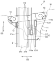
- FIG. 2 is an enlarged view of a portion in which the connection structure of FIG. 1 is provided.
- 13A and 13B are diagrams showing a state in which a guide rail is connected to a carrier plate.
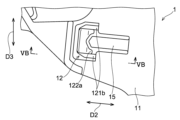
- FIG. 13 is a perspective view of a resilient claw of the carrier plate. 13 is a view showing the elastic claws of the carrier plate as viewed in the thickness direction of the main body.
- FIG. This is a cross-sectional view taken along line VB-VB in FIG. 5A.
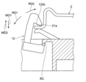
- 11 is a schematic diagram showing a force applied to the elastic claw from the guide rail when the guide rail receives a force in a direction in which the guide rail separates;
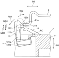
- FIG. 11 is a schematic diagram showing a state in which the elastic claw is bent in a first rotation direction when the guide rail is connected to the carrier plate;
- FIG. 13 is a schematic diagram showing a state in which the elastic claw is bent in a second rotation direction when the guide rail receives a force that separates it from the carrier plate.
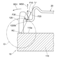
- FIG. 11 is a schematic diagram showing a reference example in which the elastic claws extend perpendicularly from a first surface of the main body.
- connection structure according to one embodiment of the present invention will be described with reference to the drawings. Note that the embodiment shown below is merely an example, and the connection structure of the present invention is not limited to the embodiment below.
- perpendicular to A and similar expressions do not only refer to a direction that is completely perpendicular to A, but also refer to a direction that is approximately perpendicular to A.
- parallel to B and similar expressions do not only refer to a direction that is completely parallel to B, but also refer to a direction that is approximately parallel to B.
- C-shape and similar expressions do not only refer to a perfect C-shape, but also refer to a shape that is visually pronounced of a C-shape (approximately a C-shape).
- connection structure S (see FIG. 1) of this embodiment includes a first member 1 and a second member 2, and the second member 2 moves relative to the first member 1 in a predetermined movement direction MD1 (see FIG. 3), thereby connecting the second member 2 to the first member 1.
- the "relative movement" of the second member 2 with respect to the first member 1 includes the second member 2 moving relative to the first member 1 while the first member 1 is stationary, the first member 1 moving relative to the second member 2 while the second member 2 is stationary, and both the first member 1 and the second member 2 moving relative to each other.
- the "predetermined movement direction” is the direction in which the second member 2 and the first member 1 move closer to each other due to the relative movement between the first member 1 and the second member 2 described above, and this direction may be a linear movement direction or a curved movement direction.
- the second member 2 moves relative to the first member 1 in a predetermined movement direction MD1 while the movement of the second member 2 in a direction substantially perpendicular to the movement direction MD1 (width direction D2, described later) relative to the first member 1 is restricted.
- the first member 1 is a carrier plate of the window regulator WR (hereinafter, the first member 1 is also referred to as the carrier plate 1)
- the second member 2 is a guide rail of the window regulator WR (hereinafter, the second member 2 is also referred to as the guide rail 2).
- the combination of the first member 1 and the second member 2 is not limited to the combination of a carrier plate and a guide rail.
- the combination of the first member and the second member may be a combination of other members, such as, for example, a combination of a casing connected to each other in a vehicle and a lid that closes the casing.
- the "carrier plate” can be read as the “first member”, and the “first member” can be read as the “carrier plate”.
- the "guide rail” can be read as the “second member”, and the “second member” can be read as the “guide rail”.
- the first member 1 and the second member 2 are configured as separate bodies, but as long as the first member and the second member are movable relative to each other and can be connected to each other, the first member and the second member may be provided as a single body (for example, the first member and the second member may be provided as a single body by a hinge and configured to be connected by rotating and moving relative to each other).
- connection structure S will be described using as an example a connection structure S provided on a window regulator WR, in which the first member is a carrier plate 1 and the second member is a guide rail 2, but the connection structure S is not limited to the following example.
- the window regulator WR includes a drive unit DR, a first cable C1 connected to the drive unit DR, and a second cable C2 connected to the drive unit DR.
- the window regulator WR also includes a carrier plate 1, which is a first member, and a guide rail 2, which is a second member.
- the connection structure S is provided in a part of the window regulator WR, specifically, in the part where the carrier plate 1 and the guide rail 2 are connected, as shown in FIG. 1.
- the window regulator WR drives the first cable C1 and the second cable C2 by the drive unit DR, and moves the carrier plate 1 along the guide rail 2. This causes the window glass W attached to the carrier plate 1 to rise and fall.
- the window regulator WR is attached to a specified mounting target. Specifically, the window regulator WR is attached to the door panel (not shown) of the vehicle body to which it is to be attached.
- the drive unit DR is a drive source that drives the first cable C1 and the second cable C2 (hereinafter collectively referred to as cable C).
- the drive unit DR may be one that drives the cable C electrically or manually.
- the drive unit DR includes a motor DR1 and a drum DR2 as shown in FIG. 1.
- the motor DR1 is configured to be capable of rotating forward and reverse, and rotates the drum DR2 forward and reverse. As a result, the cable C connected to the drum DR2 is wound onto the drum DR2 and unwound from the drum DR2.
- the cable C is operated by the drive unit DR to move the carrier plate 1 connected to the cable C in the direction in which the window glass W is raised and lowered (the up and down direction in FIG. 1).
- the cable C has a first cable C1 and a second cable C2.
- the first cable C1 is an ascending wire that pulls the carrier plate 1 in the ascending direction when the window glass W is raised.
- the second cable C2 is a descending wire that pulls the carrier plate 1 in the descending direction when the window glass W is lowered.
- the first cable C1 and the second cable C2 can be cables used in known window regulators.
- One end C11 of the first cable C1 is connected to the carrier plate 1, and the other end (not shown) of the first cable C1 is connected to the drum DR2 of the drive unit DR.
- one end C11 of the first cable C1 is connected to a first fitting portion 111a provided on the carrier plate 1 as shown in FIG. 1 and FIG. 2.
- the other end of the first cable C1 is wound around the drum DR2 and then connected to an end fixing portion (not shown) provided on the end surface of the drum DR2 or the like.
- one end C21 of the second cable C2 is connected to the carrier plate 1, and the other end (not shown) of the second cable C2 is connected to the drum DR2 of the drive unit DR.
- one end C21 of the second cable C2 is connected to a second fitting portion 111b provided on the carrier plate 1 as shown in FIG. 1 and FIG. 2.
- the other end of the second cable C2 is wound around the drum DR2 and then connected to an end fixing portion (not shown) provided on the end surface of the drum DR2 or the like.
- the first cable C1 extends from one end C11 connected to the carrier plate 1 toward the upper end of the guide rail 2, and is redirected by a direction-changing member 3 provided on the upper end side of the guide rail 2, so that the first cable C1 extends toward the lower end of the guide rail 2 (see FIG. 1).
- the second cable C2 extends from one end C21 connected to the carrier plate 1 toward the lower end of the guide rail 2.
- the guide rail 2 which is the second member, is connected to the carrier plate 1, which is the first member, as shown in Figures 1 to 3.
- the guide rail 2 guides the carrier plate 1 so that the carrier plate 1 moves along a predetermined moving path.
- the guide rail 2 has a predetermined length to move the carrier plate 1 a predetermined moving length.
- a drive unit DR is provided on the lower end side of the guide rail 2
- a direction change member 3 is provided on the upper end side.
- the guide rail 2 is fixed to an attachment object such as a door panel of a vehicle by a known fixing means such as a bolt.
- the guide rail 2 is formed in a long and narrow plate shape extending along the moving path of the carrier plate 1, and is curved in a bow shape along the length direction of the guide rail so as to follow the curvature of the attachment object (e.g., a door panel, etc.).
- the shape of the guide rail 2 is not particularly limited as long as it can guide the carrier plate 1 along a predetermined moving path.
- the material of the guide rail 2 can be, for example, metal or hard resin, but is not particularly limited as long as it has the required rigidity to withstand the tension applied by the cable C.
- the guide rail 2 has an engaged portion (first engaged portion) 21a provided on one of both sides in the width direction (left and right direction in FIG. 2) of the guide rail 2, which engages with an elastic claw 12 of the carrier plate 1 described later in the thickness direction of the guide rail 2, and an engaged portion (second engaged portion) 21b provided on the other side in the width direction, which engages with an engaging claw 112 of the carrier plate 1 described later in the thickness direction of the guide rail 2 (direction perpendicular to the paper surface in FIG. 2).
- first engaged portion 21a provided on one of both sides in the width direction (left and right direction in FIG. 2) of the guide rail 2
- an engaged portion (second engaged portion) 21b provided on the other side in the width direction, which engages with an engaging claw 112 of the carrier plate 1 described later in the thickness direction of the guide rail 2 (direction perpendicular to the paper surface in FIG. 2).
- the first engaged portion 21a and the second engaged portion 21b are flat plate-shaped portions provided at the end of the width direction of the guide rail 2 so as to be approximately parallel to the first surface 11a of the carrier plate 1 at the connection completion position (position of the solid line in FIG. 3) in which the connection of the guide rail 2 to the carrier plate 1 is completed.
- the guide rail 2 has a center portion 21c provided between the first engaged portion 21a and the second engaged portion 21b in the width direction of the guide rail 2.
- the central portion 21c extends substantially parallel to the first engaged portion 21a and the second engaged portion 21b, and is connected to the first engaged portion 21a and the second engaged portion 21b by the extension portion 21d that bends and extends substantially perpendicularly to the central portion 21c from both sides in the width direction of the central portion 21c.
- the guide rail is not limited to the shape shown in FIG. 3, and various known shapes can be adopted.
- the back surface of the first engaged portion 21a (the surface facing the first surface 11a) becomes the pressing portion 21e that presses the pressed portion 122a of the elastic claw 12 described later.
- the first member, the carrier plate 1, is connected to the second member, the guide rail 2.
- the carrier plate 1 is configured to move along the guide rail 2.
- the first member is not limited to the carrier plate 1.
- the carrier plate 1 which is the first member, comprises a main body 11 and elastic claws 12 extending from the main body 11 and configured to be elastically deformable so as to rotate around a rotation center provided at the connection point with the main body 11.
- the carrier plate 1 also has a window glass connection portion 13 as shown in Fig. 2.
- the window glass W is attached directly or indirectly to the window glass connection portion 13.
- the material constituting the carrier plate 1 is not particularly limited, but it can be made of, for example, a synthetic resin used for known carrier plates.
- the main body 11 is a base on which the elastic claws 12 are provided. As shown in Figs. 2 and 3, the main body 11 is configured to hold the guide rail 2, which is the second member, together with the elastic claws 12.
- the shape and structure of the main body 11 are not particularly limited as long as the main body 11 can serve as a base on which the elastic claws 12 are provided and can hold the guide rail 2.
- the main body 11 is configured as a plate-like member having a first surface 11a and a second surface 11b opposite the first surface 11a, as shown in Fig. 3. Note that the first surface 11a and the second surface 11b do not need to be flat surfaces, and may have irregularities on the surface, or may be curved rather than flat. In this embodiment, the first surface 11a and the second surface 11b are parallel to each other, but may be non-parallel to each other.
- the carrier plate 1 (main body 11) has a first fitting portion 111a into which the first cable C1 fits, and a second fitting portion 111b into which the second cable C2 fits.
- One end C11 of the first cable C1 engages with the first fitting portion 111a
- one end C21 of the second cable C2 engages with the second fitting portion 111b.
- the first fitting portion 111a and the second fitting portion 111b may be provided with an elastic member, such as a spring for stretching the cable C.
- the first fitting portion 111a is provided on the opposite side in the width direction from the elastic claw 12 across the guide rail 2, which is the second member
- the second fitting portion 111b is also provided on the opposite side in the width direction from the elastic claw 12 across the guide rail 2, which is the second member.
- the first fitting portion 111a and the second fitting portion 111b are not provided at a position overlapping the guide rail 2 in the width direction, but are located outside the guide rail 2 with respect to the side edge of the guide rail 2 in the width direction.
- the second fitting portion 111b is provided at a position offset in the width direction from the first fitting portion 111a, but the first fitting portion 111a and the second fitting portion 111b may be located at the same position in the width direction (positions spaced the same distance apart in the width direction from the side edge of the guide rail 2).
- the main body 11 has an engagement claw 112 with which the other of the two widthwise side portions of the guide rail 2 (second engaged portion 21b) engages.
- the other of the two widthwise side portions of the guide rail 2 (second engaged portion 21b) engages with the engagement claw 112, and one widthwise side of the guide rail 2 (first engaged portion 21a) engages with the elastic claw 12, completing the connection of the guide rail 2 to the carrier plate 1 (see solid lines in FIG. 3; connection completed position).
- the engagement claw 112 engages in the thickness direction of the guide rail 2 so that the carrier plate 1 can move along the guide rail 2, but does not engage in the length direction of the guide rail 2.
- FIG. 1 As shown in FIG.
- an engagement recess 14 into which the second engaged portion 21b of the guide rail 2 fits is provided on one surface 11a of the main body 11, and the engagement claw 112 is provided to face the second engaged portion 21b that fits into the engagement recess 14 in the thickness direction of the guide rail 2.
- the engaging claw may have other configurations, such as an engaging claw protruding from one surface 11a of the main body 11, as long as it can engage with the guide rail 2.
- the guide rail 2 rotates toward the elastic claw 12 from the state shown by the two-dot chain line in FIG. 3 to the state shown by the solid line, using the engaging point with the engaging claw 112 (inside the engaging recess 14) as a fulcrum (moves in the moving direction MD1 (see FIG. 3)).
- a part of the guide rail 2 (the first engaged portion 21a) engages with the elastic claw 12, and the guide rail 2 is connected to the carrier plate 1.
- the elastic claw 12 elastically deforms when it is connected to the guide rail 2, which is the second member. Specifically, when the guide rail 2 moves in a predetermined moving direction MD1 relative to the carrier plate 1 (or the carrier plate 1 moves relative to the guide rail 2), the elastic claw 12 elastically deforms (see FIG. 7), allowing the guide rail 2 to move to the final connection completion position (see the solid line in FIG. 3). When the guide rail 2 reaches the final connection completion position, the elastic claw 12 elastically returns to its initial state and engages with the guide rail 2. This prevents the guide rail 2 from coming off the carrier plate 1.
- the elastic claw 12 engages with one of the two widthwise side portions of the guide rail 2 (first engaged portion 21a), and the engaging claw 112 engages with the other widthwise side (second engaged portion 21b) of the guide rail 2. This prevents the guide rail 2 from coming off the carrier plate 1.
- the elastic claw 12 is made of a resin material formed integrally with the main body 11. As will be described in detail later, as shown in FIG. 7, when the guide rail 2, which is the second member, is connected to the carrier plate 1, which is the first member, the guide rail 2 presses the pressed portion 122a of the elastic claw 12, which will be described later, so that the elastic claw 12 is bent in a first rotation direction RD1 about the rotation center RC.
- the rotation center RC of the elastic claw 12 is a connection part with the main body 11, where the entire elastic claw 12 bends to change its posture when a force is applied to the elastic claw 12, which is integral with the main body 11.
- the elastic claw 12 is configured to be elastically deformed mainly at the rotation center RC, and the entire elastic claw 12 rotates around the rotation center RC (see FIG. 7).
- the part that is the rotation center RC of the elastic claw 12 has lower rigidity than other parts of the elastic claw 12 (e.g., arm part 121 and claw part 122, which will be described later, other than the parts around the rotation center RC), and is configured to be more easily deformed than other parts of the elastic claw 12 when a force is applied to the elastic claw 12 from the guide rail 2.
- the elastic claw 12 is configured to rotate around the rotation center RC. Note that when the elastic claw 12 rotates around the rotation center RC, other parts of the elastic claw 12 (e.g., arm part 121 and claw part 122) may also deform slightly.
- the rotation direction RD1 the direction in which the pressed portion 122a of the elastic claw 12 is pressed and rotated by the guide rail 2
- the rotation direction opposite to the first rotation direction RD1 is referred to as the second rotation direction RD2.
- the elastic claw 12 has an arm portion 121 extending from the center of rotation RC and a claw portion 122 provided at the end of the arm portion 121 opposite the center of rotation RC.
- the arm portion 121 is a portion that extends from the rotation center RC to the claw portion 122.
- the arm portion 121 is configured to rotate mainly around the rotation center RC.
- the shape and structure of the arm portion 121 are not limited to the structure shown in the figure.
- the arm portion 121 includes a first extension portion 121a and a second extension portion 121b, as shown in Figures 4 and 5B.
- the first extension portion 121a protrudes from the first surface 11a in the thickness direction D1 of the main body 11, which is the direction connecting the first surface 11a and the second surface 11b.
- the first extension portion 121a is connected to the second extension portion 121b, and in this embodiment, the first extension portion 121a and the second extension portion 121b are arranged in a substantially L-shape.
- a claw portion 122 protrudes from the end of the first extension portion 121a opposite to the end connected to the second extension portion 121b.
- the direction along the width direction of the guide rail 2 is called the width direction D2 of the main body 11
- the direction along the longitudinal direction of the guide rail 2 is called the height direction D3 of the main body 11.
- the thickness direction D1 of the main body 11 can be said to be the thickness direction of the guide rail 2
- the width direction D2 of the main body 11 can be said to be the width direction of the guide rail 2
- the height direction D3 of the main body 11 can be said to be the longitudinal direction of the guide rail 2.
- the first extension portion 121a is configured to have higher rigidity than the second extension portion 121b. In this case, the amount of deformation of the first extension portion 121a when the elastic claw 12 is pressed by the guide rail 2 is suppressed, making it easier for the entire elastic claw 12 to rotate around the rotation center RC.
- the first extension portion 121a is formed in a columnar (rectangular columnar) shape, and has higher rigidity than the plate-shaped second extension portion 121b.
- the second extension portion 121b extends from the first extension portion 121a toward the rotation center RC.
- the second extension portion 121b extends in the same direction (to the right in FIG. 5B) as the protruding direction of the claw portion 122 from the first extension portion 121a, as shown in FIG. 5B.
- the second extension portion 121b is configured so that the cross-sectional area at the portion that becomes the rotation center RC (the connection portion between the second extension portion 121b and the main body 11) is smaller than that of other portions of the second extension portion 121b.
- the rotation center RC which is the connection portion between the second extension portion 121b and the main body 11, is more likely to be elastically deformed, and the entire elastic claw 12 is more likely to rotate around the rotation center RC.
- the second extension portion 121b is configured by a plate-like body extending from the first extension portion 121a toward the main body 11, as shown in FIG. 4 and FIG. 5A. At the connection portion between the second extension portion 121b and the main body 11, the width is narrower than other portions of the second extension portion 121b, so that the cross-sectional area is smaller.
- the narrow portion 121c which is the connection portion between the second extension portion 121b and the main body 11, is more easily deformed than other portions of the second extension portion 121b, and becomes the rotation center RC of the elastic claw 12.
- the second extension portion 121b is composed of a pair of plate-like bodies arranged at a distance in the height direction D3 of the main body 11 (the longitudinal direction of the guide rail 2).
- the narrow portion 121c protrudes in the thickness direction D1 of the main body 11 from the base end E (see FIG.
- connection portion 113 of the main body 11 extends from the first surface 11a side of the wall portion WL facing the base end E of the second extension portion 121b toward the second extension portion 121b among the walls that define the recess CP described later. Between the base end E of the second extension portion 121b and the wall portion WL (below the connection portion 113 in FIG. 5B), a gap is provided in the width direction D2 of the main body 11.
- the rotation center RC is shown by one point for convenience of explanation, but the rotation center does not need to be only the point shown.
- the elastic claw 12 has a first extension portion 121a and a second extension portion 121b, and is configured to be approximately L-shaped when viewed in the height direction D3 of the main body 11, but the elastic claw may have other shapes other than approximately L-shaped, such as a curved approximately C-shape.
- the claw portion 122 has a pressed portion 122a that comes into contact with and is pressed by the guide rail 2 when the guide rail 2, which is the second member, moves in the moving direction MD1, and an engaging portion 122b that is located on the side of the guide rail 2 in the detachment direction MD2, which is the opposite direction to the moving direction MD1, and is capable of engaging with the guide rail 2 when the guide rail 2 is in the connection completion position (see solid line in FIG. 3 and FIG. 6) in which the guide rail 2 is connected to the carrier plate 1.
- the pressed portion 122a is a portion that comes into contact with the guide rail 2 when the guide rail 2 moves from a state before being connected to the carrier plate 1 to a connection completion position.
- the pressed portion 122a is configured to convert the force applied to the elastic claw 12 from the guide rail 2 into a force in the first rotation direction RD1 when pressed by the guide rail 2 moving in the movement direction MD1.
- the pressed portion 122a is inclined with respect to the movement direction MD1 so that the component of the force applied from the pressing portion 21e of the guide rail 2 to the pressed portion 122a faces the first rotation direction RD1 at the contact point between the guide rail 2 and the pressed portion 122a.
- the elastic claw 12 rotates in the first rotation direction RD1 around the rotation center RC.
- the engaging portion 122b When the guide rail 2 is in the connection completion position, the engaging portion 122b is located on the side of the guide rail 2 in the removal direction MD2 (upper side in FIG. 6), which is the opposite direction to the movement direction MD1. As a result, the engaging portion 122b engages with the guide rail 2 (first engaged portion 21a) in the thickness direction D1 of the main body 11, and holds the guide rail 2 in the connection completion position.
- the carrier plate 1 is provided with an auxiliary claw 15 that sandwiches the first engaged portion 21a of the guide rail 2 between the engaging portion 122b and the carrier plate 1 in the thickness direction D1 of the main body 11.
- the auxiliary claw 15 protrudes in a cantilever manner from the first surface 11a of the main body 11 toward the engaging portion 122b, and is configured to be elastically deformable in the moving direction MD1.
- the auxiliary claw 15 presses the first engaged portion 21a toward the engaging portion 122b, and sandwiches the first engaged portion 21a of the guide rail 2 together with the engaging portion 122b. This holds the guide rail 2 in a state where rattling is suppressed.
- the auxiliary claw 15 may have another configuration, or may not be provided at all.
- the "direction of force F1 applied from the guide rail 2 to the engaging portion 122b" refers to the direction of the force acting on the engaging portion 122b at the contact site between the first engaged portion 21a of the guide rail 2 and the engaging portion 122b when the guide rail 2 receives a force in the removal direction MD2.
- the force F1 is a force applied from the guide rail 2 to the engaging portion 122b when a force is applied to move the guide rail 2 relative to the carrier plate 1, but it may be a force applied from the guide rail 2 to the engaging portion 122b when a force is applied to move the carrier plate 1 relative to the guide rail 2, or a force applied from the guide rail 2 to the engaging portion 122b when a force is applied to both the carrier plate 1 and the guide rail 2.
- the virtual line L is an extension line of a line (a rotation radius of a virtual circle CC described later) connecting the rotation center RC and the contact portion of the guide rail 2 (the first engaged portion 21a) and the engaging portion 122b.
- FIG. 6 the virtual line L is an extension line of a line (a rotation radius of a virtual circle CC described later) connecting the rotation center RC and the contact portion of the guide rail 2 (the first engaged portion 21a) and the engaging portion 122b.
- the virtual circle indicated by the reference symbol CC is a circle extending the rotation locus of the contact portion between the first engaged portion 21a of the guide rail 2 and the engaging portion 122b when the elastic claw 12 rotates around the rotation center RC.
- the force F1 applied from the guide rail 2 can be broken down into a force F2 along the imaginary line L and a force F3 along the tangent direction of the imaginary circle CC, and the force F3 along the tangent direction of the imaginary circle CC acts on the elastic claw 12 in the second rotation direction RD2.
- the elastic claw 12 receives a force that rotates in the second rotation direction RD2.
- the position of the rotation center RC is set so that the elastic claw 12 receives a force F3 from the guide rail 2 that rotates in the second rotation direction RD2, as described above.
- the elastic claw 12 even if a force in the removal direction MD2 is applied to the guide rail 2, the elastic claw 12 does not receive a force that rotates in the first rotation direction RD1, which is the rotation direction in which the engagement is released, but receives a force in the second rotation direction RD2 (clockwise in Figure 8), which is the direction in which the engagement is strengthened. Therefore, the engagement between the elastic claw 12 and the guide rail 2 becomes more difficult to release.
- FIG. 9 shows a reference example in which the elastic claw 120 extends perpendicularly from the first surface 110a of the main body 110 of the carrier plate 10.
- the direction of the force F10 applied from the guide rail 20 to the engagement portion 1220b is in the first rotation direction RD1 with respect to the imaginary line Lr passing through the rotation center RC and the engagement portion 1220b.
- the force F10 applied from the guide rail 20 can be decomposed into a force F20 along the imaginary line Lr and a force F30 along the tangent direction of the imaginary circle Cr, and the force F30 along the tangent direction of the imaginary circle Cr acts on the elastic claw 120 in the first rotation direction RD1.
- the direction in which the elastic claw 120 rotates when the guide rail 20 is connected and the direction in which the elastic claw 120 rotates when the guide rail 20 is about to be detached are the same (first rotation direction RD1). Therefore, when a force in the detachment direction MD2 is applied to the guide rail 20, the elastic claw 120 rotates in the first rotation direction RD1, which is a direction in which the engagement between the elastic claw 120 and the guide rail 20 is released, and the guide rail 20 may be detached. In contrast, in this embodiment, as described above, when a force in the detachment direction MD2 is applied to the guide rail 2, the elastic claw 12 rotates in the second rotation direction RD2, which is a direction in which the engagement between the elastic claw 12 and the guide rail 2 becomes stronger. Therefore, the guide rail 2 is prevented from being detached from the carrier plate 1.
- the direction of the force applied to the elastic claw 12 is opposite when the guide rail 2 is connected and when the guide rail 2 is about to detach. Therefore, even if the entire elastic claw 12 or the area around the rotation center RC is made flexible so that the elastic claw 12 is more likely to elastically deform when the guide rail 2 is connected, the elastic claw 12 will simply be more likely to rotate in the second rotation direction RD2 when the guide rail 2 is about to detach. Therefore, even if the elastic claw is made more likely to deform in order to make it easier to connect the guide rail 2 to the carrier plate 1, it is possible to prevent the guide rail 2 from detaching from the carrier plate 1.
- the elastic claw 120 if the elastic claw 120 is made more flexible by thinning the entire elastic claw 120 or the area around the rotation center RC, the elastic claw 120 will bend more easily when connecting the guide rail 20 to the carrier plate 10, making it easier to connect the guide rail 20.
- the elastic claw 120 rotates in the first rotation direction RD1, so that the guide rail 20 also becomes more easily detached from the carrier plate 10.
- the elastic claw 12 even if the elastic claw 12 is made more elastically deformable to make it easier to assemble the guide rail 2 to the carrier plate 1 with less force, the guide rail 2 does not become more easily detached from the carrier plate 1.
- the carrier plate 1 has a first fitting portion 111a and a second fitting portion 111b provided on the opposite side of the guide rail 2 in the width direction of the guide rail 2 from the elastic claw 12, and the first cable C1 and the second cable C2 fit into the first fitting portion 111a and the second fitting portion 111b, respectively.
- a rotational moment acts around a rotation axis extending in the extension direction of the guide rail 2 at the engagement point between the guide rail 2 and the carrier plate 1.
- the rotational moment is more likely to act, and the carrier plate 1 becomes more likely to come off the guide rail 2.
- the above-mentioned rotational moment applied to the carrier plate 1 becomes a force that rotates the elastic claw 12 in the second rotational direction RD2, making it more difficult to disengage the engagement between the elastic claw 12 and the guide rail 2.
- the first extension portion 121a extends protruding from the first surface 11a in the thickness direction D1 of the main body 11, and the second extension portion 121b extends from the first extension portion 121a toward the rotation center RC in the same direction as the protruding direction of the claw portion 122 from the first extension portion 121a, at a length longer than the protruding amount of the claw portion 122 from the first extension portion 121a.
- the rotation center RC located on the base end E side of the second extension portion 121b is located at a position farther from the first extension portion 121a in the width direction D2 (a position closer to the center of the width direction of the guide rail 2) than the tip end of the claw portion 122 (the contact portion between the engagement portion 122b and the guide rail 2).
- the virtual line L connecting the rotation center RC and the engaging portion 122b inclines away from the center of the width direction of the guide rail 2 as it moves away from the first surface 11a of the main body 11 of the carrier plate 1.
- the force F1 applied from the guide rail 2 to the engaging portion 122b is directed in a direction substantially perpendicular to the first surface 11a (strictly speaking, in a direction slightly inclined toward the center of the guide rail 2 with respect to the direction perpendicular to the first surface 11a). Therefore, when the protrusion amount of the second extension portion 121b from the first extension portion 121a is greater than the protrusion amount of the claw portion 122 from the first extension portion 121a, the component force F3 in the tangential direction of the virtual circle CC is directed in the second rotation direction RD2. This makes it possible to reliably apply a force in the second rotation direction RD2 to the elastic claw 12, and to prevent the guide rail 2 from being released from the carrier plate 1.
- the engaging portion 122b is inclined so as to approach the first surface 11a as it moves from the first extension portion 121a to the tip of the claw portion 122.
- the magnitude of the force toward the second rotation direction RD2 can be made larger compared to when the engaging portion 122b extends parallel to the first surface 11a. That is, the force from the guide rail 2 applied in a direction perpendicular to the surface of the engaging portion 122b is inclined toward the second rotation direction RD2 because the engaging portion 122b is inclined so as to approach the first surface 11a as it moves from the first extension portion 121a to the tip of the claw portion 122.
- the component force F3 in the tangential direction of the virtual circle CC into which the force applied to the engaging portion 122b is resolved is larger compared to when the engaging portion 122b is parallel to the first surface 11a. This makes it possible to prevent the guide rail 2 from coming off the carrier plate 1.
- the main body 11 has a recess CP extending from the first surface 11a toward the second surface 11b.
- a part of the first extension portion 121a and the second extension portion 121b are arranged in this recess CP.
- the recess CP is configured to penetrate from the first surface 11a to the second surface 11b, but the recess CP may be a non-penetrating recess with a bottom.
- a connection structure including a first member and a second member, the second member being connected to the first member by moving relatively to the first member in a predetermined moving direction, the first member being: The main body, an elastic claw extending from the main body and configured to be elastically deformable so as to rotate around a rotation center provided at a connection point with the main body;
- the elastic claw includes an arm portion extending from the rotation center and a claw portion provided at an end of the arm portion opposite to the rotation center, the claw portion includes a pressed portion that is in contact with and pressed by the second member when the second member moves in the moving direction, and an engaging portion that is located on a detachment direction side, which is the opposite direction to the moving direction, with respect to the second member when the second member is in a connection completion position in which the second member is connected to the first member, and is engageable with the second member;
- the elastic claw is configured to bend in a first rotation direction about the rotation center by the second member pressing the pressed portion when the second member is connected to the first member,
- the main body of the first member is a plate-like member having a first surface and a second surface opposite to the first surface,
- the arm portion is a first extension portion that protrudes and extends from the first surface in a thickness direction of the main body, the thickness direction being a direction connecting the first surface and the second surface;
- the connection structure described in (1) is provided with a second extension portion extending from the first extension portion toward the rotation center in the same direction as the protruding direction of the claw portion from the first extension portion, at a length longer than the protruding amount of the claw portion from the first extension portion.
- connection structure described in (1) or (2) in which the main body has a recess extending from the first surface toward the second surface, and a portion of the first extension and the second extension are disposed within the recess.
- the first member is a carrier plate of a window regulator
- the second member is a guide rail of the window regulator
- the window regulator includes a drive unit, a first cable connected to the drive unit, and a second cable connected to the drive unit
- the elastic claw of the first member is configured to engage with one of both side portions in a width direction of the second member,
Landscapes
- Engineering & Computer Science (AREA)
- Mechanical Engineering (AREA)
- Window Of Vehicle (AREA)
- Power-Operated Mechanisms For Wings (AREA)
- Snaps, Bayonet Connections, Set Pins, And Snap Rings (AREA)
- Connection Of Plates (AREA)
Abstract
Description
本体と、
前記本体から延び、前記本体との接続箇所に設けられた回転中心まわりに回転するように弾性変形可能に構成された弾性爪とを備え、
前記弾性爪は、前記回転中心から延びるアーム部と、前記アーム部の前記回転中心とは反対側の端部に設けられた爪部とを備え、
前記爪部は、前記第2部材が前記移動方向に移動する際に、前記第2部材と接触して押圧される被押圧部と、前記第2部材が前記第1部材に接続された状態となる接続完了位置にあるときに、前記第2部材に対して、前記移動方向とは反対方向となる離脱方向側に位置し、前記第2部材と係合可能な係合部とを備え、
前記弾性爪は、前記第2部材が前記第1部材に接続される際に、前記第2部材によって前記被押圧部が押圧されることで、前記回転中心を中心とした第1の回転方向に撓むように構成され、
前記第2部材に対して前記離脱方向に力が加わったときに、前記第2部材から前記係合部に対して加わる力の方向が、前記回転中心と前記係合部とを通る仮想線に対して、前記第1の回転方向とは反対側となる第2の回転方向側を向いて、前記弾性爪が前記第2の回転方向に回転する力を前記第2部材から受けるように、前記回転中心の位置が設定されている、接続構造。
前記アーム部は、
前記第1の面および第2の面を繋ぐ方向である前記本体の厚さ方向に、前記第1の面から突出して延びる第1延在部と、
前記第1延在部から前記回転中心に向かって、前記爪部の前記第1延在部からの突出方向と同方向に、前記爪部の前記第1延在部からの突出量よりも長い長さで延びる第2延在部と、を備えている、(1)に記載の接続構造。
前記第2部材は、前記ウインドレギュレータのガイドレールであり、
前記ウインドレギュレータは、駆動部と、前記駆動部に接続された第1ケーブルと、前記駆動部に接続された第2ケーブルとを備え、
前記第1部材の前記弾性爪は、前記第2部材の幅方向の両側部のうちの一方に係合するように構成され、
前記第1部材は、前記第2部材を挟んで前記弾性爪とは前記幅方向で反対側に設けられた、前記第1ケーブルが嵌合する第1嵌合部と、前記第2部材を挟んで前記弾性爪とは前記幅方向で反対側に設けられた、前記第2ケーブルが嵌合する第2嵌合部とを備えている、(1)~(3)のいずれか1つに記載の接続構造。
11、110 本体
11a、110a 第1の面
11b 第2の面
111a 第1嵌合部
111b 第2嵌合部
112 係合爪
113 接続部
12、120 弾性爪
121 アーム部
121a 第1延在部
121b 第2延在部
121c 幅狭部
122 爪部
122a 被押圧部
122b、1220b 係合部
13 窓ガラス接続部
14 係合凹部
15 補助爪
2、20 第2部材(ガイドレール)
21a 第1被係合部
21b 第2被係合部
21c 中央部
21d 延在部
21e 押圧部
3 方向転換部材
C ケーブル
C1 第1ケーブル
C11 第1ケーブルの一端
C2 第2ケーブル
C21 第2ケーブルの一端
CC ガイドレールの第1被係合部と係合部との接触部位の回転軌跡を延長した仮想円
CP 凹部
D1 本体の厚さ方向
D2 本体の幅方向
D3 本体の高さ方向
DR 駆動部
DR1 モータ
DR2 ドラム
E 基端部
F1、F10 ガイドレールから係合部に対して加わる力
F2、F20 仮想線に沿った力
F3、F30 仮想円の接線方向に沿う力
L、Lr 回転中心と係合部とを通る仮想線
MD1 移動方向
MD2 離脱方向
RC 回転中心
RD1 第1の回転方向
RD2 第2の回転方向
S 接続構造
W 窓ガラス
WL 壁部
WR ウインドレギュレータ
Claims (4)
- 第1部材と第2部材とを備え、前記第2部材が前記第1部材に対して所定の移動方向に相対移動することで、前記第2部材が前記第1部材に接続される接続構造であって、前記第1部材は、
本体と、
前記本体から延び、前記本体との接続箇所に設けられた回転中心まわりに回転するように弾性変形可能に構成された弾性爪とを備え、
前記弾性爪は、前記回転中心から延びるアーム部と、前記アーム部の前記回転中心とは反対側の端部に設けられた爪部とを備え、
前記爪部は、前記第2部材が前記移動方向に移動する際に、前記第2部材と接触して押圧される被押圧部と、前記第2部材が前記第1部材に接続された状態となる接続完了位置にあるときに、前記第2部材に対して、前記移動方向とは反対方向となる離脱方向側に位置し、前記第2部材と係合可能な係合部とを備え、
前記弾性爪は、前記第2部材が前記第1部材に接続される際に、前記第2部材によって前記被押圧部が押圧されることで、前記回転中心を中心とした第1の回転方向に撓むように構成され、
前記第2部材に対して前記離脱方向に力が加わったときに、前記第2部材から前記係合部に対して加わる力の方向が、前記回転中心と前記係合部とを通る仮想線に対して、前記第1の回転方向とは反対側となる第2の回転方向側を向いて、前記弾性爪が前記第2の回転方向に回転する力を前記第2部材から受けるように、前記回転中心の位置が設定されている、接続構造。 - 前記第1部材の前記本体は、第1の面および前記第1の面とは反対側の第2の面を有する板状部材であり、前記アーム部は、
前記第1の面および第2の面を繋ぐ方向である前記本体の厚さ方向に、前記第1の面から突出して延びる第1延在部と、
前記第1延在部から前記回転中心に向かって、前記爪部の前記第1延在部からの突出方向と同方向に、前記爪部の前記第1延在部からの突出量よりも長い長さで延びる第2延在部と、を備えている、請求項1に記載の接続構造。 - 前記本体が前記第1の面から前記第2の面に向かって延びる凹部を備え、前記第1延在部の一部および前記第2延在部が前記凹部内に配置されている、請求項2に記載の接続構造。
- 前記第1部材は、ウインドレギュレータのキャリアプレートであり、前記第2部材は、前記ウインドレギュレータのガイドレールであり、前記ウインドレギュレータは、駆動部と、前記駆動部に接続された第1ケーブルと、前記駆動部に接続された第2ケーブルとを備え、前記第1部材の前記弾性爪は、前記第2部材の幅方向の両側部のうちの一方に係合するように構成され、前記第1部材は、前記第2部材を挟んで前記弾性爪とは前記幅方向で反対側に設けられた、前記第1ケーブルが嵌合する第1嵌合部と、前記第2部材を挟んで前記弾性爪とは前記幅方向で反対側に設けられた、前記第2ケーブルが嵌合する第2嵌合部とを備えている、請求項1~3のいずれか1項に記載の接続構造。
Priority Applications (2)
| Application Number | Priority Date | Filing Date | Title |
|---|---|---|---|
| CN202480022560.9A CN120882946A (zh) | 2023-06-28 | 2024-06-26 | 连接结构 |
| MX2025014432A MX2025014432A (es) | 2023-06-28 | 2025-12-01 | Estructura de conexion |
Applications Claiming Priority (2)
| Application Number | Priority Date | Filing Date | Title |
|---|---|---|---|
| JP2023-105913 | 2023-06-28 | ||
| JP2023105913A JP2025005653A (ja) | 2023-06-28 | 2023-06-28 | 接続構造 |
Publications (1)
| Publication Number | Publication Date |
|---|---|
| WO2025005100A1 true WO2025005100A1 (ja) | 2025-01-02 |
Family
ID=93939297
Family Applications (1)
| Application Number | Title | Priority Date | Filing Date |
|---|---|---|---|
| PCT/JP2024/023073 Ceased WO2025005100A1 (ja) | 2023-06-28 | 2024-06-26 | 接続構造 |
Country Status (4)
| Country | Link |
|---|---|
| JP (1) | JP2025005653A (ja) |
| CN (1) | CN120882946A (ja) |
| MX (1) | MX2025014432A (ja) |
| WO (1) | WO2025005100A1 (ja) |
Citations (3)
| Publication number | Priority date | Publication date | Assignee | Title |
|---|---|---|---|---|
| JPH08303427A (ja) * | 1995-05-12 | 1996-11-19 | Toshiba Corp | ロック構造 |
| JP2010259295A (ja) * | 2009-04-28 | 2010-11-11 | Sumitomo Wiring Syst Ltd | ヒンジ式閉止体を備えた電装用部品 |
| JP2017008483A (ja) * | 2015-06-16 | 2017-01-12 | 株式会社ハイレックスコーポレーション | 対象物移動装置 |
-
2023
- 2023-06-28 JP JP2023105913A patent/JP2025005653A/ja active Pending
-
2024
- 2024-06-26 WO PCT/JP2024/023073 patent/WO2025005100A1/ja not_active Ceased
- 2024-06-26 CN CN202480022560.9A patent/CN120882946A/zh active Pending
-
2025
- 2025-12-01 MX MX2025014432A patent/MX2025014432A/es unknown
Patent Citations (3)
| Publication number | Priority date | Publication date | Assignee | Title |
|---|---|---|---|---|
| JPH08303427A (ja) * | 1995-05-12 | 1996-11-19 | Toshiba Corp | ロック構造 |
| JP2010259295A (ja) * | 2009-04-28 | 2010-11-11 | Sumitomo Wiring Syst Ltd | ヒンジ式閉止体を備えた電装用部品 |
| JP2017008483A (ja) * | 2015-06-16 | 2017-01-12 | 株式会社ハイレックスコーポレーション | 対象物移動装置 |
Also Published As
| Publication number | Publication date |
|---|---|
| JP2025005653A (ja) | 2025-01-17 |
| MX2025014432A (es) | 2026-01-07 |
| CN120882946A (zh) | 2025-10-31 |
Similar Documents
| Publication | Publication Date | Title |
|---|---|---|
| JP6583243B2 (ja) | ベルトモール取付構造 | |
| JP3157491B2 (ja) | 可撓体の案内支持チェーン | |
| CN104736786B (zh) | 滑轮装置 | |
| US20070180773A1 (en) | Dual-guided single rail window regulator | |
| JP2014210440A (ja) | 自動車のウエザーストリップ | |
| WO2019188253A1 (ja) | ウインドレギュレータ | |
| WO2015019827A1 (ja) | 車両のスライド窓及びトリムボードの固定方法 | |
| WO2025005100A1 (ja) | 接続構造 | |
| US11286705B1 (en) | Cable guide assembly for a window regulator | |
| US20190195000A1 (en) | Window regulator cable guide | |
| JP4965121B2 (ja) | 電子機器の取付け構造 | |
| JP2025005652A (ja) | 接続構造 | |
| JP5359572B2 (ja) | 車両用デフレクター装置 | |
| JP7315521B2 (ja) | キャリアプレート及び対象物移動装置 | |
| JP2020165087A (ja) | ウインドレギュレータ | |
| WO2008072316A1 (ja) | ウインドレギュレータおよび治具 | |
| JP3416321B2 (ja) | ウインドウガラスレギュレータ | |
| CN206397332U (zh) | 升降装置 | |
| JP7846646B2 (ja) | キャリアプレートおよびウインドレギュレータ | |
| JP7789635B2 (ja) | キャリアプレートおよびウインドレギュレータ | |
| JP4615051B2 (ja) | 天吊り型情報機器仮固定機構 | |
| JP3958060B2 (ja) | ディスプレイ装置 | |
| JP2005171486A (ja) | 車両スライド扉のパワースライド装置におけるテンション機構 | |
| CN220374371U (zh) | 一种汽车前扶手及汽车 | |
| US20260109202A1 (en) | Window regulator |
Legal Events
| Date | Code | Title | Description |
|---|---|---|---|
| 121 | Ep: the epo has been informed by wipo that ep was designated in this application |
Ref document number: 24831960 Country of ref document: EP Kind code of ref document: A1 |
|
| WWE | Wipo information: entry into national phase |
Ref document number: 202480022560.9 Country of ref document: CN |
|
| WWP | Wipo information: published in national office |
Ref document number: 202480022560.9 Country of ref document: CN |
|
| WWE | Wipo information: entry into national phase |
Ref document number: MX/A/2025/014432 Country of ref document: MX |
|
| WWP | Wipo information: published in national office |
Ref document number: MX/A/2025/014432 Country of ref document: MX |
|
| NENP | Non-entry into the national phase |
Ref country code: DE |