WO2024262535A1 - 水着 - Google Patents
水着 Download PDFInfo
- Publication number
- WO2024262535A1 WO2024262535A1 PCT/JP2024/022221 JP2024022221W WO2024262535A1 WO 2024262535 A1 WO2024262535 A1 WO 2024262535A1 JP 2024022221 W JP2024022221 W JP 2024022221W WO 2024262535 A1 WO2024262535 A1 WO 2024262535A1
- Authority
- WO
- WIPO (PCT)
- Prior art keywords
- fabric
- swimsuit
- fiber
- yarn
- mass
- Prior art date
- Legal status (The legal status is an assumption and is not a legal conclusion. Google has not performed a legal analysis and makes no representation as to the accuracy of the status listed.)
- Ceased
Links
Images







Classifications
-
- A—HUMAN NECESSITIES
- A41—WEARING APPAREL
- A41D—OUTERWEAR; PROTECTIVE GARMENTS; ACCESSORIES
- A41D7/00—Bathing gowns; Swim-suits, drawers, or trunks; Beach suits
-
- D—TEXTILES; PAPER
- D01—NATURAL OR MAN-MADE THREADS OR FIBRES; SPINNING
- D01F—CHEMICAL FEATURES IN THE MANUFACTURE OF ARTIFICIAL FILAMENTS, THREADS, FIBRES, BRISTLES OR RIBBONS; APPARATUS SPECIALLY ADAPTED FOR THE MANUFACTURE OF CARBON FILAMENTS
- D01F6/00—Monocomponent artificial filaments or the like of synthetic polymers; Manufacture thereof
- D01F6/58—Monocomponent artificial filaments or the like of synthetic polymers; Manufacture thereof from homopolycondensation products
- D01F6/70—Monocomponent artificial filaments or the like of synthetic polymers; Manufacture thereof from homopolycondensation products from polyurethanes
-
- D—TEXTILES; PAPER
- D02—YARNS; MECHANICAL FINISHING OF YARNS OR ROPES; WARPING OR BEAMING
- D02G—CRIMPING OR CURLING FIBRES, FILAMENTS, THREADS, OR YARNS; YARNS OR THREADS
- D02G3/00—Yarns or threads, e.g. fancy yarns; Processes or apparatus for the production thereof, not otherwise provided for
- D02G3/22—Yarns or threads characterised by constructional features, e.g. blending, filament/fibre
- D02G3/38—Threads in which fibres, filaments, or yarns are wound with other yarns or filaments, e.g. wrap yarns, i.e. strands of filaments or staple fibres are wrapped by a helically wound binder yarn
-
- D—TEXTILES; PAPER
- D03—WEAVING
- D03D—WOVEN FABRICS; METHODS OF WEAVING; LOOMS
- D03D15/00—Woven fabrics characterised by the material, structure or properties of the fibres, filaments, yarns, threads or other warp or weft elements used
- D03D15/20—Woven fabrics characterised by the material, structure or properties of the fibres, filaments, yarns, threads or other warp or weft elements used characterised by the material of the fibres or filaments constituting the yarns or threads
-
- D—TEXTILES; PAPER
- D03—WEAVING
- D03D—WOVEN FABRICS; METHODS OF WEAVING; LOOMS
- D03D15/00—Woven fabrics characterised by the material, structure or properties of the fibres, filaments, yarns, threads or other warp or weft elements used
- D03D15/20—Woven fabrics characterised by the material, structure or properties of the fibres, filaments, yarns, threads or other warp or weft elements used characterised by the material of the fibres or filaments constituting the yarns or threads
- D03D15/283—Woven fabrics characterised by the material, structure or properties of the fibres, filaments, yarns, threads or other warp or weft elements used characterised by the material of the fibres or filaments constituting the yarns or threads synthetic polymer-based, e.g. polyamide or polyester fibres
-
- D—TEXTILES; PAPER
- D03—WEAVING
- D03D—WOVEN FABRICS; METHODS OF WEAVING; LOOMS
- D03D15/00—Woven fabrics characterised by the material, structure or properties of the fibres, filaments, yarns, threads or other warp or weft elements used
- D03D15/30—Woven fabrics characterised by the material, structure or properties of the fibres, filaments, yarns, threads or other warp or weft elements used characterised by the structure of the fibres or filaments
- D03D15/37—Woven fabrics characterised by the material, structure or properties of the fibres, filaments, yarns, threads or other warp or weft elements used characterised by the structure of the fibres or filaments with specific cross-section or surface shape
-
- D—TEXTILES; PAPER
- D03—WEAVING
- D03D—WOVEN FABRICS; METHODS OF WEAVING; LOOMS
- D03D15/00—Woven fabrics characterised by the material, structure or properties of the fibres, filaments, yarns, threads or other warp or weft elements used
- D03D15/40—Woven fabrics characterised by the material, structure or properties of the fibres, filaments, yarns, threads or other warp or weft elements used characterised by the structure of the yarns or threads
- D03D15/44—Woven fabrics characterised by the material, structure or properties of the fibres, filaments, yarns, threads or other warp or weft elements used characterised by the structure of the yarns or threads with specific cross-section or surface shape
-
- D—TEXTILES; PAPER
- D03—WEAVING
- D03D—WOVEN FABRICS; METHODS OF WEAVING; LOOMS
- D03D15/00—Woven fabrics characterised by the material, structure or properties of the fibres, filaments, yarns, threads or other warp or weft elements used
- D03D15/40—Woven fabrics characterised by the material, structure or properties of the fibres, filaments, yarns, threads or other warp or weft elements used characterised by the structure of the yarns or threads
- D03D15/47—Woven fabrics characterised by the material, structure or properties of the fibres, filaments, yarns, threads or other warp or weft elements used characterised by the structure of the yarns or threads multicomponent, e.g. blended yarns or threads
-
- D—TEXTILES; PAPER
- D03—WEAVING
- D03D—WOVEN FABRICS; METHODS OF WEAVING; LOOMS
- D03D15/00—Woven fabrics characterised by the material, structure or properties of the fibres, filaments, yarns, threads or other warp or weft elements used
- D03D15/50—Woven fabrics characterised by the material, structure or properties of the fibres, filaments, yarns, threads or other warp or weft elements used characterised by the properties of the yarns or threads
- D03D15/56—Woven fabrics characterised by the material, structure or properties of the fibres, filaments, yarns, threads or other warp or weft elements used characterised by the properties of the yarns or threads elastic
-
- D—TEXTILES; PAPER
- D06—TREATMENT OF TEXTILES OR THE LIKE; LAUNDERING; FLEXIBLE MATERIALS NOT OTHERWISE PROVIDED FOR
- D06M—TREATMENT, NOT PROVIDED FOR ELSEWHERE IN CLASS D06, OF FIBRES, THREADS, YARNS, FABRICS, FEATHERS OR FIBROUS GOODS MADE FROM SUCH MATERIALS
- D06M15/00—Treating fibres, threads, yarns, fabrics, or fibrous goods made from such materials, with macromolecular compounds; Such treatment combined with mechanical treatment
- D06M15/19—Treating fibres, threads, yarns, fabrics, or fibrous goods made from such materials, with macromolecular compounds; Such treatment combined with mechanical treatment with synthetic macromolecular compounds
- D06M15/21—Macromolecular compounds obtained by reactions only involving carbon-to-carbon unsaturated bonds
- D06M15/263—Macromolecular compounds obtained by reactions only involving carbon-to-carbon unsaturated bonds of unsaturated carboxylic acids; Salts or esters thereof
-
- D—TEXTILES; PAPER
- D06—TREATMENT OF TEXTILES OR THE LIKE; LAUNDERING; FLEXIBLE MATERIALS NOT OTHERWISE PROVIDED FOR
- D06M—TREATMENT, NOT PROVIDED FOR ELSEWHERE IN CLASS D06, OF FIBRES, THREADS, YARNS, FABRICS, FEATHERS OR FIBROUS GOODS MADE FROM SUCH MATERIALS
- D06M15/00—Treating fibres, threads, yarns, fabrics, or fibrous goods made from such materials, with macromolecular compounds; Such treatment combined with mechanical treatment
- D06M15/19—Treating fibres, threads, yarns, fabrics, or fibrous goods made from such materials, with macromolecular compounds; Such treatment combined with mechanical treatment with synthetic macromolecular compounds
- D06M15/37—Macromolecular compounds obtained otherwise than by reactions only involving carbon-to-carbon unsaturated bonds
- D06M15/643—Macromolecular compounds obtained otherwise than by reactions only involving carbon-to-carbon unsaturated bonds containing silicon in the main chain
-
- A—HUMAN NECESSITIES
- A41—WEARING APPAREL
- A41D—OUTERWEAR; PROTECTIVE GARMENTS; ACCESSORIES
- A41D2400/00—Functions or special features of garments
- A41D2400/24—Reducing drag or turbulence in air or water
-
- A—HUMAN NECESSITIES
- A41—WEARING APPAREL
- A41D—OUTERWEAR; PROTECTIVE GARMENTS; ACCESSORIES
- A41D2500/00—Materials for garments
- A41D2500/20—Woven
Definitions
- the present invention relates to swimwear.
- a method for reducing water resistance by using a weave structure with many floating threads in the length direction of swimsuit fabric has also been proposed. It is described that water resistance can be effectively reduced by using raw yarn with a special cross-sectional shape that has a narrowed inlet groove for the floating thread.
- buoyancy and water resistance are particularly important elements in competitive swimsuits that aim to improve competitive performance.
- One way to solve water resistance is to increase the number of floating threads, but this results in larger voids, and although the initial buoyancy is excellent, the voids will retain water over time in water and when rubbed, which will actually reduce buoyancy.
- the voids will generate turbulence, which will lead to increased surface water resistance. In other words, it has been difficult to achieve both durable buoyancy and water resistance until now.
- Patent Document 2 Although the technology of Patent Document 2 is excellent at reducing water resistance, increasing the number of floating threads increases the interstitial spaces in the fabric structure, so although it has excellent buoyancy in the short term, over time and as the fabric is kneaded by exercise, water is retained in the interstitial spaces, making the fabric heavier in water and reducing its buoyancy.
- Patent Document 3 is effective in reducing water resistance, but does not take buoyancy into consideration at all.
- the present invention aims to reduce water resistance while improving buoyancy and durability.
- a swimsuit including a woven fabric in which a covering yarn having a polyurethane elastic yarn as a core yarn and a synthetic fiber filament as a sheath yarn is arranged in at least a part of the warp yarn and the weft yarn,
- the polyurethane elastic yarn contains a cationic high molecular weight compound A having a number average molecular weight of 2000 or more in the range of 0.5 to 10 mass %, and also contains an inorganic chlorine degradation inhibitor B, the mass ratio (A/B) of the cationic high molecular weight compound A to the inorganic chlorine degradation inhibitor B being in the range of 0.3 to 3, and also contains silicone;
- the synthetic fiber filament is composed of synthetic fibers including single fibers having a surface with a plurality of grooves, at least a portion of which is continuous in the fiber length direction, the grooves having a depth of 1.0 to 10.0 ⁇ m, an inlet width of 0.5 to 10.0 ⁇ m, and
- the swimsuit described in (1) in which the plain weave fabric and the weft double weave fabric are alternately repeated is arranged in at least a part of the area covering from the navel to above the knees.
- the swimsuit according to any one of (1) to (6), wherein the swimsuit covers only the upper body, and the mass ratio of the fabric in the swimsuit is, in the front body region and the back body region, front body region:back body region 4-50:50-96.
- the swimsuit according to any one of (1) to (5) and (8), wherein the swimsuit covers the upper and lower body, and the mass ratio of the fabric in the swimsuit is, in the front body region and the back body region, front body region:back body region 7-45:55-93.
- the swimsuit according to any one of (1) to (5), (8) and (9), which is a swimsuit covering the upper and lower body, and in which the mass ratio of the fabric in the swimsuit is upper body region:lower body region 2-45:55-98 in the upper body region covering from the head to the center of gravity and the lower body region covering from the center of gravity to above the knees.
- (11) The swimsuit according to any one of (1) to (10), wherein the polyurethane elastic yarn has a fluorine/carbon (F/C) ratio of 0.030 or more in elemental mass concentration by scanning electron microscope-energy dispersive X-ray spectroscopy (SEM-EDX).
- the present invention makes it possible to provide a swimsuit that has excellent durable buoyancy and reduces surface water resistance.
- FIG. 2 is a schematic diagram for explaining the cross-sectional shape of one example of a single fiber used in the present invention.
- FIG. 2 is an enlarged schematic view illustrating a groove portion of an example of a single fiber used in the present invention.
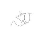
- FIG. 2 is an enlarged schematic view of a protrusion of an example of a single fiber used in the present invention.
- FIG. 2 is a schematic explanatory diagram showing a buoyancy measuring method.
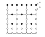
- FIG. 2 is a close-up view of one embodiment of a distribution hole arrangement in a final distribution plate.
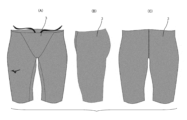
- 1A, 1B, and 1C are diagrams showing a swimsuit (male swimsuit for competitive swimming) according to a first embodiment, in which (A) is a front view, (B) is a side view, and (C) is a back view.
- 13A, 13B, and 13C are diagrams showing a swimsuit (male swimsuit for competitive swimming) according to a second embodiment, in which (A) is a front view, (B) is a side view, and (C) is a back view.
- 13A, 13B, and 13C are diagrams showing a swimsuit (male swimsuit for competitive swimming) according to a third embodiment, in which (A) is a front view, (B) is a side view, and (C) is a back view.
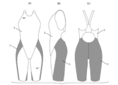
- 13A, 13B, and 13C are diagrams showing a swimsuit (women's competitive swimsuit) according to a fourth embodiment, in which (A) is a front view, (B) is a side view, and (C) is a back view.
- 13A, 13B, and 13C are diagrams showing a swimsuit (women's swimsuit for competitive swimming) according to a fifth embodiment, in which (A) is a front view, (B) is a side view, and (C) is a back view.
- FIGS. 13A, 13B, and 13C are diagrams showing a swimsuit (women's swimsuit for competitive swimming) according to a sixth embodiment, in which (A) is a front view, (B) is a side view, and (C) is a back view.
- the covering coated yarn in the present invention uses a synthetic multifilament fiber as a sheath yarn.
- the synthetic multifilament yarn includes, as constituent monofilaments, synthetic fibers including monofilaments having, on their surfaces, a plurality of grooves at least partially continuous in the fiber length direction. As illustrated in Fig.
- the fiber has a cross-sectional shape in which a plurality of grooves 12 having wide portions on the outer periphery are present on either side of protrusions 11 (hereinafter, the above cross-sectional shape may be referred to as a "special cross-sectional shape” and a fiber having a special cross-sectional shape may be referred to as a "special cross-sectional fiber").
- the depth (H) of the grooves in the special cross-sectional shape is 1.0 ⁇ m to 10.0 ⁇ m.
- Water droplets that adhere to the fiber surface enter the grooves due to their own weight and the kneading effect, and when they reach the bottom of the groove, the water droplets adhere to the grooves and become wet, causing a deterioration in water retention and buoyancy.
- the grooves are deep, the water droplets are pushed up to the top of the grooves by the surface tension of the water droplets, so they do not get wet and exhibit water repellency.
- the single fiber filament diameter is 12 to 26 ⁇ m, so if the grooves are designed to be excessively deep, there is a concern that the strength of the raw yarn will decrease. For this reason, the depth of the grooves is 10 ⁇ m or less, and preferably 8 ⁇ m or less.
- the groove depth is preferably 1 ⁇ m or more, as described above, and more preferably 2 ⁇ m or more.
- the depth (H) of the groove in the special cross-section fiber is defined as the distance from the intersection of the line 21 connecting the ends of the protrusions 11 present on either side of the groove in FIG. 2 (the distance of this line 21 is defined as the width (W1) of the groove entrance) to the center point 13 (not shown in FIG. 2) of the cross section perpendicular to the longitudinal direction of the synthetic fiber filament (the center point of the circumscribing circle that most often circumscribes the tip of the protrusion), and the perpendicular line 22, which connects the ends of the protrusions, to the tangent point 23 of the perpendicular line 22 and the fiber polymer portion. Also, as shown in FIG.
- the center point 13 of the fiber is defined as the center point of the circle (hereinafter referred to as the circumscribing circle) that most often circumscribes the tip of the protrusion in the fiber polymer cross section, and the diameter of the circumscribing circle is defined as the fiber diameter (D) 14.
- the width (W1) of the groove entrance in the above special cross-sectional shape is 0.5 ⁇ m to 10.0 ⁇ m.
- the width of the groove entrance is within the above preferred range, high water repellency can be achieved by obtaining surface tension due to the surface tension of water droplets. If the width of the groove entrance is too small, the water repellent agent will not penetrate into the groove and it will be difficult to obtain water repellency, so a width of 0.5 ⁇ m or more is preferable, and 1.0 ⁇ m or more is even more preferable. Furthermore, if the width of the groove entrance is too large, water will penetrate into the groove, causing a deterioration in water retention and buoyancy. Therefore, a width of 10 ⁇ m or less is preferable, and a width of 8 ⁇ m or less is even more preferable.
- the groove wide section width (W2) is the maximum width measured along the center line from the outer periphery toward the fiber center, and is taken as the groove wide section width (W2) 24.
- W2/W1 of the groove wide section width (W2) to the groove inlet width (W1) is 1.3 or more, more air can be trapped inside, which is preferable in terms of improving buoyancy and water repellency.
- W2/W1 is more preferably 1.5 or more, and even more preferably 1.8 or more.
- W2/W1 is 3.0 or less, which suppresses cracking of the protrusions due to rubbing caused by wearing and is excellent in maintaining the shape of the groove inlet. By maintaining the shape of the groove inlet, the function can be maintained.
- the ratio (H/D) of the fiber diameter (D) to the depth (H) of the groove is 0.15 or more and 0.25 or less. This allows a sufficient air layer to be formed inside, allowing functions such as water repellency and high buoyancy to be exhibited, while there is no risk of performance degradation due to deformation or destruction when the protrusions forming the grooves are subjected to external forces.
- H/D is more preferably 0.17 or more and less than 0.22.
- the special cross-sectional shape satisfies the following formula.
- W1 width of groove entrance ( ⁇ m)
- W2 Width of the wide groove portion ( ⁇ m)
- H Groove depth ( ⁇ m)
- F fiber diameter ( ⁇ m)
- the width 31 (Pout) of the tip of the protrusion, the width (W1) of the entrance of the groove, and the width (Pmin) 32 of the bottom surface of the adjacent groove to the width (Pout) 31 of the tip of the protrusion satisfy the following formula.
- the width (Pout) 31 of the tip of the protrusion is the shortest distance connecting one tip of the protrusion and the other tip of the protrusion, and is the distance represented by the symbol 31 in Figure 3.
- the width (Pout) 31 of the tip of the protrusion is preferably 10.0 ⁇ m or less.
- the width 32 (Pmin) of the bottom surface of the protrusion is, in other words, the distance connecting the tangent points of the inscribed circles of adjacent grooves across the protrusion, and is the distance indicated by the symbol 32 in FIG. 3.
- the shape of the grooves in the special cross-section fiber when observed in a cross section perpendicular to the length of the fiber, is preferably teardrop-shaped, hexagonal, etc., with a wide portion wider than the entrance width in the range from the entrance to the bottom of the groove, and the width of the groove gradually narrows from the wide portion toward the bottom of the groove.
- the number of grooves in the special cross-section fiber is preferably multiple; if there is only one groove, depending on the orientation of the fiber, the groove may not be present at the boundary surface with water, and the water repellency improvement effect cannot be obtained.
- the number of grooves is preferably 2 to 32, and more preferably 4 to 16. If the number of grooves is within the above preferred range, the width of the protrusions in the cross-sectional shape of the fiber will not become too small, and fibrils or fuzz will not occur on the product surface during processing or when the product is used.
- the core-sheath composite fibers is composed of two types of polymers, and the cross-section of the core component has the above-mentioned shape, and the special cross-sectional fiber can be obtained by dissolving the sheath component with a solvent or the like.
- the core component polyamides such as polyethylene terephthalate, polybutylene terephthalate, polytrimethylene terephthalate, and nylon 6 can be used.
- the sheath component from the viewpoint of simplifying the dissolution process, copolymerized polyesters, polylactic acid, polyvinyl alcohol, etc. that are easily soluble in aqueous solvents or hot water are preferable, and in particular, polyesters and polylactic acids copolymerized with polyethylene glycol and sodium sulfoisophthalic acid alone or in combination are preferable from the viewpoint of ease of handling and easy dissolution in aqueous solvents.
- the mass ratio of the core component to the sheath component is preferably in the range of 50:50 to 90:10.
- the synthetic fiber multifilament yarn used in the present invention is at least partially the above-mentioned special cross-section fiber, and the synthetic fiber multifilament yarn may be entirely the above-mentioned special cross-section fiber or may be other multifilaments.
- the other multifilaments may be multifilaments having a fiber cross-section other than the above-mentioned special cross-section fiber.
- Polyethylene terephthalate, polybutylene terephthalate, polytrimethylene terephthalate, nylon 6, and other polyamides can be used as materials for constituting such multifilaments. Even in this case, non-crimped multifilaments are preferable in terms of reducing the void ratio of the woven fabric.
- non-shrink fiber so-called non-shrink fiber
- non-shrink fiber means that there is no active crimping, such as with false twist processing or apparent crimp composite fibers (the weaving crimp that inevitably occurs during weaving is not considered to be crimping).
- Another method for reducing inter-woven voids is to interweave elastic fibers to create a high-density fabric.
- the covering coated yarn in the present invention has a polyurethane elastic yarn as a core yarn.
- the polyurethane elastic yarn contains 0.5 to 10 mass% of a cationic high molecular weight compound A having a number average molecular weight of 2000 or more, and also contains an inorganic chlorine degradation inhibitor B, with the mass ratio of A/B being in the range of 0.3 to 3. This produces a large synergistic effect, allowing for excellent chlorine degradation resistance and water repellency. Further details about the polyurethane elastic yarn are disclosed, for example, in JP 2020-169400 A.
- the cationic high molecular weight compound used in the present invention is not particularly limited as long as it has an amino group in its structure, but from the viewpoint of the chlorine deterioration resistance and yellowing of the polyurethane elastic yarn, it is particularly preferable to use a compound having only tertiary amino groups in its molecule among primary to tertiary amino groups. If the number average molecular weight of the cationic high molecular weight compound is less than 2000, it will fall off due to friction with the guide or knitting needle during knitting of the polyurethane elastic yarn, or will flow out during processing in a bath such as dyeing, which will deteriorate the water repellency, so the number average molecular weight must be 2000 or more.
- the number average molecular weight is preferably in the range of 2000 to 10,000. More preferably, it is in the range of 2000 to 4000.
- the number average molecular weight of the cationic high molecular weight compound can be measured by gel permeation chromatography (GPC) in terms of polystyrene.
- the inclusion of the cationic high molecular weight compound described above can enhance the water repellency of the polyurethane elastic yarn.
- the cationic high molecular weight compound is preferably contained in an amount of 0.5% by mass or more and 10% by mass or less, and more preferably 0.5% by mass or more and 4% by mass or less, relative to the fiber mass.
- the polyurethane elastic yarn in the present invention contains silicone.
- silicone within a specific range of 0.5% by mass to 20% by mass is added to the polyurethane elastic yarn, for example, in the form of an oil.
- This silicone is originally intended to reduce tension fluctuations when the polyurethane elastic yarn is unwound during the manufacture of the fabric, and to suppress thread breakage caused by unwound tension fluctuations even in fine elastic fibers, but in this case, it significantly contributes to improving the water-repellent processing.
- the content of silicone in the processing agent is preferably 0.5 to 10% by mass, preferably 1 to 6% by mass, on a dry mass basis. This improves the affinity with the water-repellent processing agent.
- any water-repellent processing agent may be used, but it is preferable to use a processing agent with an F/C ratio of 0.030 or more in the element mass concentration of SEM-EDX on the polyurethane elastic yarn.
- an F/C ratio of 0.030 or more indicates that the amount of fluorine-based water repellent attached is large. If the F/C ratio is less than 0.030, the amount of fluorine-based water repellent attached is small, and sufficient low wettability tends not to be obtained. It is even more preferable that the F/C ratio is 0.045 or more.
- the covering coated yarn in the present invention has the above polyurethane elastic fiber as the core yarn and the synthetic fiber filament as the sheath yarn, but the covering method is not particularly limited as long as the above polyurethane elastic fiber is covered with the synthetic fiber filament by a method such as single covering or double covering.
- the draft ratio of the above polyurethane elastic fiber used for the core yarn is preferably 1.5 to 5 times, and preferably 2 to 4 times from the viewpoints of productivity and stretchability of the resulting woven fabric.
- the woven fabric of the present invention has the above-mentioned covering coating yarns disposed on at least a portion of the warp and weft threads. It may be used on either the warp or weft threads, or on both. It may also be used on a portion of the warp or weft threads. In terms of achieving the effects of the present invention, it is preferable that the covering coating yarns are used on all of the warp and weft threads.
- the weave is not particularly limited to plain weave, twill weave, multi-layered weave, etc., but it is preferable to include at least a plain weave fabric and a weft double weave fabric in terms of reducing water resistance and buoyancy.
- a fabric woven at a high density is preferred to achieve low water retention, and a total cover factor (Cf) of 2300 or more is preferable. If the total cover factor is small, the number of intersections will be reduced, and the weaving yarns will be less restrained, which will not only cause problems with twisting and snagging, but the weave structure will become looser, which will increase the gaps between the structures and cause concerns that this will lead to a decrease in water retention when worn. For this reason, a total cover factor of 2500 or more is more preferable, and 2700 or more is even more preferable.
- the porosity of the fabric is 75% or less, and preferably 70% or less.
- the porosity here refers to the porosity per volume, and refers to the parameter expressed by the following formula.
- V Apparent volume of the fabric (actually measured volume)
- v True volume of the fabric (volume of the synthetic fiber calculated from the density of the components that make up the synthetic fiber)
- the void ratio calculated from the above parameters includes voids between the yarns of the synthetic multifilament yarn that make up the weave, voids between the single fibers that make up the synthetic multifilament yarn, and voids due to hollows such as grooves in special cross-section fibers.
- special cross-section fibers with hollows are used, many fine air layers are formed compared to round cross-sections. By forming such fine air layers, it is possible to achieve a high level of the contradictory properties of low water retention and high buoyancy, so it is desirable for many fine air layers to exist in the fabric.
- the degree of voids formed by the grooves of the special cross-section fibers contained in the woven fabric is set to a void ratio caused by the fiber cross-sectional shape of a single fiber having multiple grooves on its surface in the range of 5 to 30%. Of these, a void ratio of 10 to 30% is preferable.
- the void ratio caused by the fiber cross-sectional shape of a single fiber having multiple grooves on its surface referred to here is a value calculated by the following method.
- the area of the void is calculated by subtracting the area of the actual cross section of the special cross section fiber (actual area) from the area of the circumscribing circle that most closely contacts the outer periphery of the cross section perpendicular to the fiber length direction of the special cross section fiber, and the void ratio is the ratio to the area of the circumscribing circle. If the fiber cross section is round and solid (hereinafter referred to as solid round cross section fiber), the outer periphery will theoretically match the circumscribing circle, and the void ratio will be 0%. On the other hand, in the case of a special cross section, the area of the circumscribing circle will be larger than the area of the special cross section fiber itself.
- the difference area is divided by the area of the circumscribing circle, and the result expressed as a percentage is the "void ratio due to the fiber cross section shape of a single fiber having multiple grooves on its surface" (hereinafter referred to as the "void ratio due to the cross section shape of a special cross section fiber) per single fiber of the special cross section fiber.
- Vcs ⁇ (Ac-a)/Ac ⁇ 100%
- Vcs void ratio (%) due to the cross-sectional shape of a special cross-sectional fiber per single fiber
- Ac Area of the circumscribed circle that is in contact with the cross section of the special cross section fiber the most a: Actual area of the cross section of the special cross section fiber
- the cross-sectional shape of the core-sheath composite fiber before the elution of the sheath component is a solid round cross-section
- the special cross-sectional shape is expressed by the elution of the sheath component, and there is no significant difference in density between the eluted component and the non-eluted component (for example, as a guideline, the ratio of the absolute value of the difference in density between the two to the density of the higher density is 10% or less)
- the elution rate when the elution process is performed to elute the sheath component from the core-sheath composite fiber may be used as a substitute for the porosity due to the cross-sectional shape of the special cross-section fiber per single fiber in the special cross-section fiber (hereinafter referred to as the "substitution method").
- the void percentage due to the cross-sectional shape of the special cross-section fiber per single fiber can be defined as the void percentage due to the cross-sectional shape of the special cross-section fiber in the woven fabric by multiplying the void percentage due to the cross-sectional shape of the special cross-section fiber per single fiber by the blending ratio of the solid cross-section fiber (equivalent to the blending ratio of the core-sheath composite fiber in the case where the above-mentioned substitution method can be used).
- the special cross-section fibers are extracted from the woven fabric, the void ratio resulting from the cross-sectional shape of the special cross-section fiber per single fiber is determined, and the void ratio resulting from the cross-sectional shape of the special cross-section fiber can be determined by multiplying it by the blend ratio of solid cross-section fibers assumed above.
- the void ratio resulting from the cross-sectional shape of the special cross-section fiber per single special cross-section fiber is multiplied by the blend ratio of solid cross-section fibers assumed above of 100% by mass to determine the void ratio resulting from the cross-sectional shape of the special cross-section fiber.
- the special cross-section fiber used in the present invention uses core-sheath composite fibers as the raw fiber, and the special cross-section fiber can express a special cross-sectional shape by dissolving the sheath component of the core-sheath composite fiber.
- the dissolving, dyeing, and finishing processes required for this are carried out by refining, relaxing, and drying the grey fabric, and then heat-fixing the width with an intermediate set to dissolve the sheath component.
- the fabric is dyed and reduction-washed if it is made of polyester material, or fixed if it is made of nylon material, washed in hot water, and dried.
- a water-repellent treatment and various functional treatments as necessary are preferably carried out, followed by a finishing set process.
- the swimsuit of the present invention is water-repellent.
- the water-repellent treatment may be performed at any stage, such as at the thread, fabric, or swimsuit.
- the water-repellent agent used in the water-repellent treatment may be any of fluorine-based, silicone-based, paraffin-based, etc., but among them, fluorine-based water-repellents are preferable in terms of water-repellent performance.
- fluorine-based water-repellents with 8 or more carbon atoms are preferable in terms of performance, but PFOA-free fluorine-based water-repellents with 6 carbon atoms (C6 water-repellents) that are unlikely to generate perfluorooctanoic acid (PFOA) are more preferable from the perspective of environmental impact.
- C6 water-repellents fluorine-based water-repellents with 6 carbon atoms
- PFOA perfluorooctanoic acid
- C0 water-repellents such as paraffin-based, acrylic-based, and other hydrocarbon-based, and silicone-based, either alone or in combination.
- a crosslinking agent in combination with the water repellent.
- the crosslinking agent at least one of melamine-based resins, blocked isocyanate-based compounds, glyoxal-based resins, and imine-based resins can be used, and there is no particular limitation on the crosslinking agent.
- a water-repellent finish to the surface of the fabric, the inside of the fabric, and the backside of the fabric, it is preferable to apply the water-repellent finish using a method such as Pad-Dry-Cure.
- the water-repellent treatment on the surface, inside and back of the fabric can be confirmed by observing a cross section of the fabric in the thickness direction with a scanning electron microscope (SEM) and checking the presence or absence of a water-repellent coating on the surface of each fiber present on the surface, inside and back of the fabric.
- SEM scanning electron microscope
- the water repellency is grade 4 or higher according to the JIS L1092:2009 spray method, and it is also desirable that the grade is maintained at 3 or higher even after 20 washes according to the JIS L0217:1995 103 method.
- the water repellency of water repellent materials decreases with washing, and in particular, when a non-fluorine-based water repellent is used as the water repellent, the washing durability of the water repellency is inferior to that of a fluorine-based water repellent.
- the use of special cross-section fibers can compensate for the decrease in water repellency, and excellent water repellency can be maintained even after washing.
- the woven fabric of the present invention preferably has a water retention rate of 50% or less by mass of the amount of woven material after 60 minutes, more preferably 40% or less by mass, and even more preferably 30% or less by mass.
- a water retention rate of 0% by mass is most preferable, but in practice, 3% by mass is assumed to be the lower limit.
- the weight of the material when worn is even 0.1 g lighter in terms of improving athletic performance
- the buoyancy of the woven fabric is preferably 0.0170 N or more per 1 g of fabric, more preferably 0.0185 N or more, and even more preferably 0.0200 N or more. Also, since excessive buoyancy impairs ease of movement in the water, it is preferable for the buoyancy to be 0.0300 N or less.
- the buoyancy per gram of fabric after 20 minutes is preferably 0.0165 N or more, more preferably 0.0180 N or more, and even more preferably 0.0195 N or more.
- the reason that the buoyancy after 20 minutes is lower than at the beginning is because the coarse voids between the tissue retain water over time, and with a material with many fine voids like the present invention, the decrease in buoyancy can be minimized.
- the woven fabric of the present invention preferably has a tear strength of 8N or more, more preferably 10N or more, and even more preferably 12N or more, as measured in accordance with JIS L1096:1999.
- a method for obtaining a woven fabric with the above tear strength is to use a single yarn of 1.5 dtex or more and, as described above, set the total cover factor to 3000 or less.
- the woven fabric preferably has a burst strength of 200 kPa or more, more preferably 300 kPa or more, and even more preferably 400 kPa or more, as measured in accordance with JIS L1096:1999.
- One example of a method for obtaining a woven fabric with the above burst strength is to use a thick single yarn and weave it with a high total cover factor. Specifically, it can be obtained by using a single yarn of 1.5 dtex or more and setting the total cover factor to 2500 or more.
- the swimsuit of the present invention includes, at least in the part covering the buttocks, a portion of the above-mentioned fabric in which plain weave fabric and weft double weave fabric are repeated alternately.
- the periodic riblets formed on the surface of the fabric have the effect of suppressing the generation of turbulence, thereby reducing water resistance.
- the swimsuit of the present invention has improved buoyancy due to the use of the above-mentioned fabric of the present invention, and the riblet structure of the above-mentioned fabric traps air bubbles, forming air layers not only inside the fabric and between the raw yarns but also on the surface of the fabric, resulting in a synergistic effect of further improving buoyancy.
- the apparent density was measured according to the method described in "Chapter 3 Measurement of apparent fineness of fibers extracted from fabric after removing non-fibrous substances" in which non-fibrous substances were removed by the method described in ISO1833-1, and in the case of dyed and finished products without resin processing (including water repellent and softening processing), the apparent density was measured according to the method described in "Chapter 2 Measurement of apparent fineness of fibers extracted from fabric without removing non-fibrous substances".
- the mass of the yarn was measured by adjusting it to moisture equilibrium under standard conditions (20°C, 65% RH) (Method A) and calculating it using the following formula.
- the number of measurements was 40 or more.
- Ld Ws / L ⁇ n Ld: Apparent fineness (tex) of yarn adjusted under standard conditions Ws: Mass of yarn removed from fabric (g) L: Average length when pulled straight (m) n: Number of weighed yarns
- Basis Weight was measured as the mass per unit area under standard conditions (20°C, 65% RH) according to JIS L1096:2010, 8.3.2. Method A. That is, three 200 mm x 200 mm test pieces were taken, and the mass (g) of each was measured after leaving them for one day under standard conditions, and the mass per m2 (g/ m2 ) was calculated using the following formula, and the average value was calculated and rounded to an integer.
- Sm W/A
- W Mass of test piece under standard conditions (g)
- Thickness The thickness was measured in accordance with 8.4 of JIS L1096:2010 using a thickness gauge to measure the thickness of five different points of a humidity-conditioned sample according to Method A when the sample was pressed at a pressure of 23.5 kPa for 10 seconds, and the average value was calculated.
- the apparent volume (V) of the test piece was calculated by multiplying the thickness calculated in (4) by the area of the test piece prepared in (3). Furthermore, the true volume (v) of the fiber structure was calculated from the mass (Wc) of the test piece and the density and mixture ratio of the components constituting the synthetic fiber used by the following formula. Regarding the density and mixture ratio, if they are known, the values may be used, but if they are unknown and evaluated from the woven fabric, the density is measured according to JIS L 1013:2021 8.17.2 (density gradient tube method) as necessary, and the mixture ratio is measured by JIS L 1030-2:2021 dissolution method or dissolution method.
- Vall ⁇ (V-v)/(V) ⁇ 100 Vall: Void ratio of fabric (%) V: Apparent volume of the fabric (actually measured volume) v: True volume of the fabric (as described above, the volume of the synthetic fiber calculated from the density of the components that make up the synthetic fiber)
- the knitted fabrics made from the core-sheath composite fibers with a circular cross section before leaching produced in the examples and comparative examples were produced using a 28G cylindrical knitting machine, and after 24 hours of humidity conditioning under standard conditions (20°C, 65% RH), the mass (Wb) before leaching was measured.
- the fiber was hung to dry for 24 hours under standard conditions (20°C, 65% RH), after which the mass (Wa) after dissolving the sheath components was measured and the dissolution rate was calculated using the formula below.
- the dissolution rate was compared with the design value for the fiber to confirm that 100% of the sheath components had been dissolved. This dissolution rate was taken as the porosity due to the cross-sectional shape of the special cross-section fiber per single fiber of the special cross-section fiber.
- the porosity due to the cross-sectional shape of a single fiber having multiple grooves on its surface was calculated by multiplying the mixture ratio of core-sheath composite fibers in the fabric before dissolution by the dissolution rate.
- the water repellency was measured according to JIS L1092:2009 7.2 Water repellency test (spray test), and three samples of about 200 mm x 200 mm were collected. Using a water repellency tester, 250 ml of water was placed in a funnel so that the longitudinal direction of the sample was parallel to the water flow, and the water was sprayed on the sample for 20 to 25 seconds. Next, the sample holder was removed from the device, one end was held horizontally, the front side of the test piece was turned down, and the other end was lightly hit against a hard object once to remove water droplets, and the other end was rotated 180° and the same operation as before was performed to remove excess water droplets. The wet state of the sample was judged by comparing it with a comparative sample while it was still attached to the holder.
- the water-repellent fabric was washed using method 103 described in JIS L0217:1995 "Textile product handling symbols and their labeling methods.” The fabric was washed 20 times, and the water-repellent performance after washing was evaluated using the spray test described above.
- Water retention rate (%) ((mass after treatment - mass before treatment) / mass before treatment) x 100
- FIG. 4 is a schematic explanatory diagram showing the buoyancy measurement method.
- the buoyancy test device 40 water 42 was placed in a container 41, a test sample 48 was placed therein, and a hanging balance (electronic balance, AUY220, manufactured by Shimadzu Corporation) serving as a weighing scale 43 was fixed on top of the water.
- the weighing scale 43 was held between a support 44 and a plate 46, and a support rod 45 and a wire mesh 47 were attached.
- the wire mesh 47 was placed in water, and the test sample 48 was hung from the weighing scale 43 with the wire mesh 47 sandwiched between them, and the load in water (value measured by the hanging balance) (WA2) was measured.
- the buoyancy was calculated by subtracting WA1 from WA2.
- Five randomly taken samples of 3 cm length and 4 cm width were measured from the fabric, and the average value was calculated. For the fabric samples used in measuring WA1, the load when dry was measured.
- Fabric A A spinneret designed to have nylon 6 (N6) (density: 1.14 g/cm 3 ) in the core and polyethylene terephthalate (copolymerized PET1) (density: 1.26 g/cm 3 ) in which 8.0 mol % of 5-sodium sulfoisophthalic acid and 10 wt % of polyethylene glycol having a molecular weight of 1,000 were copolymerized was used to melt the core and sheath separately at 270°C, and then the melt was allowed to flow into the spinneret, and the composite polymer flow was discharged from the discharge hole to obtain a core-sheath composite fiber drawn yarn (33 dtex/10 filaments).
- the distribution plate immediately above the discharge plate had the portion located at the interface between the core component and the sheath component arranged in the pattern shown in Figure 5, so that teardrop-shaped grooves with eight wide portions were formed on the surface of one single fiber filament.
- the sheath component was arranged so as to be sandwiched between the core components discharged from the distribution holes for the core component, and a polymer flow was formed in which the core-sheath type composite was formed with a special groove shape controlled.
- the core-sheath composite ratio was adjusted to 80:20 by mass.
- DMAc N,N-dimethylacetamide
- a DMAc solution containing ethylenediamine and diethylamine was added to the solution in which the reactants were dissolved, to prepare a polyurethane urea solution in which the solid content in the polymer was 35 mass%.
- a cationic high molecular weight compound As a cationic high molecular weight compound, a cationic high molecular weight compound having a number average molecular weight of 2600 was produced by reacting t-butyldiethanolamine with methylene-bis-(4-cyclohexyl isocyanate). The number average molecular weight of the cationic high molecular weight compound was measured by gel permeation chromatography (GPC) under the following measurement conditions. (Measurement conditions) Standard material: polystyrene Column: 2 SHODEX KF-806M columns manufactured by Showa Denko K.K. Solvent: N,N-dimethylacetamide (DMAc) at 1 ml/min Temperature: 40°C Detector: Differential refractometer (RI detector)
- the resulting cationic high molecular weight compound was dissolved in DMAc to prepare a solution (A1) with a concentration of 35% by mass.
- a 35% by mass DMAc dispersion was prepared using calcium carbonate Hakuenka A (CaCO 3 , average primary particle size: 1.0 ⁇ m) manufactured by Shiraishi Kogyo Co., Ltd. as a chlorine degradation inhibitor.
- a horizontal mill DYNO-MILKDL manufactured by WILLYA. BACHOFEN was used, and 85% zirconia beads were filled and finely dispersed uniformly at a flow rate of 80 g/min to prepare a DMAc dispersion B1 (35% by mass) of synthetic carbonate.
- ethylene-1,2-bis(3,3-bis[3-t-butyl-4-hydroxyphenyl]butyrate (Clariant Corporation) was used as a one-hindered phenol compound.
- "Hostanox" (registered trademark) O3) manufactured by Epson Corporation was dissolved in DMAc to prepare a solution (C1) with a concentration of 35% by mass.
- Polymer solutions X1, A1, B1, and C1 were mixed in ratios of 97% by mass, 1% by mass, 3% by mass, and 1% by mass, respectively, to prepare spinning solution Y1.
- the mass ratio (A/B) of the cationic high molecular weight compound and the inorganic chlorine degradation inhibitor was 0.33 based on the amounts of the polymer solutions added.
- This spinning solution Y1 was dry-spun at a winding speed of 580 m/min to produce polyurethane elastic yarns (44 dtex, 55 dtex, and 78 dtex) (Z1), which were wound up while being coated with a silicone oil as a treatment agent.
- the silicone oil was a treatment agent (oil) of 96% silicone (polydimethylsiloxane), 3% St-Mg, and 1% dispersant, which was applied at 6% by dry weight.
- the core-sheath composite fiber drawn yarn obtained in the manner described above was used as a sheath yarn, which is a non-crimped yarn that has not been subjected to yarn processing such as false twisting, and a polyurethane elastic yarn was used as a core yarn to produce a single covering yarn.
- the following three types of yarn were obtained depending on the fineness of the polyurethane elastic yarn.
- Yarn A Core-sheath composite fiber drawn yarn (33 dtex) x polyurethane elastic yarn (78 dtex)
- Yarn B Core-sheath composite fiber drawn yarn (33 dtex) x polyurethane elastic yarn (55 dtex)
- Yarn C Core-sheath composite fiber drawn yarn (33 dtex) x polyurethane elastic yarn (44 dtex)
- a stretch fabric was woven in which plain weave sections and double weft weave sections were alternately repeated.
- the resulting fabric was a mixture of 65% nylon and 35% polyurethane by mass.
- the fabric was relaxed scoured in the open-weave state in the usual manner, and then pre-set.
- a 1% aqueous sodium hydroxide solution was used for jet dyeing at 100°C for 60 minutes in a bath ratio of 1:30, which dissolved 100% of the sheath components, making the core-sheath composite fibers in the fabric into special cross-section fibers.
- the fabric was dyed black in the usual manner with an acid dye using a jet dyeing machine.
- a soaping process was performed using an aqueous surfactant solution, and then a fixing process was performed in the usual manner.
- the obtained woven fabric had a warp density of 198 threads/2.54 cm and a weft density of 205 threads/2.54 cm, and after elution, the mixture ratio was 60% by mass of nylon 6 (Ny) and 40% by mass of PU.
- the basis weight was 115 g/ m2 and the thickness was 0.32 mm.
- the porosity of the woven fabric was calculated to be 67.1% from these, the density of the components constituting the nylon fiber of 1.14 g/ cm3 , and the density of the PU fiber of 1.0 g/ cm3 .
- the elution treatment caused 20% more voids than the core-sheath composite fiber with a round cross section before elution, and since the mixture ratio of the core-sheath composite fiber before elution was 65% by mass, the porosity due to the cross-sectional shape of the special cross-section fiber was 13.0%.
- the width of the tip of the protrusion was 4.9 ⁇ m, and no peeling or collapse of the protrusions occurred during the processing process.
- the water repellent fabric obtained by this method had a water repellent coating formed on the fiber surface on the front, inside the fabric and back, and had low water retention and high buoyancy both initially and over time, making it suitable for wearing underwater.
- the obtained woven fabric had a warp density of 197 threads/2.54 cm, a weft density of 176 threads/2.54 cm, and a blend ratio of Ny 73% by mass and PU 27% by mass. It also had a basis weight of 108 g/ m2 and a thickness of 0.30 mm, and the void ratio of the woven fabric was calculated to be 67.3% using the same calculation method as for Fabric A. In addition, since all the raw yarns used had a round cross section, the void ratio due to the cross-sectional shape of the fiber was 0%.
- the water repellency, water retention and buoyancy of the obtained fabric were evaluated using a spray method, and the evaluation results are shown in Table 1.
- the water-repellent fabric obtained by this method has a water repellent coating formed on the fiber surfaces on the front, inside the fabric and back, so it has excellent water retention but low buoyancy and is considered to be insufficient for the performance required for wearing underwater.
- Table 1 also shows the evaluation results of Fabric C, which was made by replacing only the warp threads of Fabric A with those with a round cross section. Although slightly inferior to Fabric A, Fabric C also had low water retention and high buoyancy both initially and over time, making it suitable for wearing underwater.
- the inventors created a weft double-weave fabric using FTY (original yarn) made with synthetic fiber filaments with voids in the fiber cross section as the sheath yarn and polyurethane elastic yarn, to which water repellent agents are easily attached, as in Fabric A, and confirmed that the buoyancy effect was greater than that of fabrics without voids. Furthermore, the inventors confirmed that the surface friction resistance due to the weave structure was reduced compared to plain weave structures.
- FTY original yarn
- the inventor developed a swimsuit in which this fabric is partially placed from the center of gravity to the lower legs. Normally, the center of buoyancy during swimming is closer to the head than the center of gravity, so a moment in the direction of gravity is applied to the legs.
- the swimmer By placing fabric with a high buoyancy effect from the center of gravity to the lower legs, the swimmer can easily assume a horizontal position relative to the water surface, get the sensation that the lower legs are floating, and maintain a posture with less resistance.
- FIG. 4 is a schematic explanatory diagram showing the buoyancy measurement method.
- water 42 was placed in a container 41
- a swimsuit which was a test material 48
- a hanging balance electrostatic balance, AUY220, manufactured by Shimadzu Corporation
- the test device holds the weighing scale 43 between a support 44 and a plate 46, and a support rod 45 and a wire mesh 47 were attached. As shown in FIG. 4, the wire mesh 47 was placed in water, and the test sample 48 was hung from the weighing scale 43 with the wire mesh 47 sandwiched between them, and the load in water (value measured by the hanging balance) (WA2) was measured. Buoyancy was calculated by WA1-WA2.
- Fabric A and Fabric B were used to sew men's competitive swimming swimsuits of Examples 1 to 3 and Comparative Example 1 shown in Table 2.
- Each Example and Comparative Example has the mass ratio of Fabric A and Fabric B shown in the table.
- the swimsuits of Examples 1 to 3 had a buoyancy effect that could be felt, and also had stability and ease of movement in a standing position, making them suitable for competitive swimming, compared to the swimsuit of Comparative Example 1, which did not use Fabric A.
- the first to third embodiments are men's swimsuits for competitive swimming
- the fourth to sixth embodiments are women's swimsuits for competitive swimming.
- the first portion 3, colored gray, is made of fabric A
- the second portion 5, which is uncolored is made of fabric B.
- Table 4 shows the usage ratio (mass ratio) of fabric A in each embodiment.
- the boundary between the upper body region and the lower body region is the center of gravity (below the navel), with the upper body region corresponding to the region from the head to the center of gravity, and the lower body region corresponding to the region from the center of gravity to above the knees.
- the boundary between the front body region and the back body region is the side line.
- the swimsuit according to the above-mentioned examples and embodiments includes a woven fabric in which a covering yarn having a polyurethane elastic yarn as a core yarn and a synthetic fiber filament as a sheath yarn is arranged in at least a portion of the warp and weft yarns.
- the polyurethane elastic yarn contains 0.5-10% by mass of cationic high molecular weight compound A with a number average molecular weight of 2000 or more, contains inorganic chlorine degradation inhibitor B, and the mass ratio (A/B) of cationic high molecular weight compound A to inorganic chlorine degradation inhibitor B is in the range of 0.3-3, and contains silicone.
- the synthetic fiber filament is composed of synthetic fibers including monofilaments at least a part of which has a plurality of grooves on its surface that are continuous in the fiber length direction, and the grooves are 1.0-10.0 ⁇ m deep, 0.5-10.0 ⁇ m wide at the entrance, and 10.0 ⁇ m or less wide at the tip of the protrusion, and the void ratio due to the cross-sectional shape of the fiber of the grooves is 5-30%.
- the fabric includes a plain weave fabric and a weft double weave fabric with an internal void ratio of 75% or less, and the swimsuit includes an alternating portion of the plain weave fabric and the weft double weave fabric at least in a position that covers the buttocks, and is treated with a water repellent finish.
- the swimsuit has a portion in which the plain weave fabric and the weft double weave fabric are repeated alternately in at least a part of the area covering from the navel to above the knees. This allows for high buoyancy.
- the alternately repeated plain weave and weft double weave portions may be arranged throughout the swimsuit as in Example 1 and Embodiment 2. This can provide even greater buoyancy.
- the above-mentioned fabric may be used for the main fabric of the swimsuit, or for the lining of the swimsuit.
- the mass ratio of the above-mentioned fabric in the swimsuit is 35% or more, as shown in Table 4.
- the mass ratio of the woven fabric in the swimsuit is 35% or more, as shown in Table 4.
- protrusion 12 groove 13: center point 14: fiber diameter (D) 21: Straight line 22: Perpendicular line 23: Point of contact between perpendicular line 22 and fiber polymer portion 24: Width of wide portion of groove (W2) 31: Width of the tip of the protrusion (Pout) 32: Width of bottom surface of protrusion (Pmin) 40: Buoyancy test apparatus 41: Container 42: Water 43: Weight scale 44: Support 45: Support rod 46: Support plate 47: Wire mesh 48: Test sample 51: Distribution hole for core component 52: Distribution hole for sheath component
Landscapes
- Engineering & Computer Science (AREA)
- Textile Engineering (AREA)
- Chemical & Material Sciences (AREA)
- Chemical Kinetics & Catalysis (AREA)
- Mechanical Engineering (AREA)
- General Chemical & Material Sciences (AREA)
- Woven Fabrics (AREA)
- Treatments For Attaching Organic Compounds To Fibrous Goods (AREA)
Priority Applications (3)
| Application Number | Priority Date | Filing Date | Title |
|---|---|---|---|
| EP24825936.8A EP4732697A1 (en) | 2023-06-21 | 2024-06-19 | Swimsuit |
| JP2024561969A JPWO2024262535A1 (https=) | 2023-06-21 | 2024-06-19 | |
| CN202480034698.0A CN121194719A (zh) | 2023-06-21 | 2024-06-19 | 泳装 |
Applications Claiming Priority (2)
| Application Number | Priority Date | Filing Date | Title |
|---|---|---|---|
| JP2023101977 | 2023-06-21 | ||
| JP2023-101977 | 2023-06-21 |
Publications (1)
| Publication Number | Publication Date |
|---|---|
| WO2024262535A1 true WO2024262535A1 (ja) | 2024-12-26 |
Family
ID=93935527
Family Applications (1)
| Application Number | Title | Priority Date | Filing Date |
|---|---|---|---|
| PCT/JP2024/022221 Ceased WO2024262535A1 (ja) | 2023-06-21 | 2024-06-19 | 水着 |
Country Status (5)
| Country | Link |
|---|---|
| EP (1) | EP4732697A1 (https=) |
| JP (1) | JPWO2024262535A1 (https=) |
| CN (1) | CN121194719A (https=) |
| TW (1) | TW202507103A (https=) |
| WO (1) | WO2024262535A1 (https=) |
Citations (5)
| Publication number | Priority date | Publication date | Assignee | Title |
|---|---|---|---|---|
| JPH06228820A (ja) | 1993-01-28 | 1994-08-16 | Kanebo Ltd | 耐久撥水性軽量繊維構造物 |
| WO2015151820A1 (ja) | 2014-03-31 | 2015-10-08 | 美津濃株式会社 | ストレッチ織物及びこれを含むスポーツ用衣類と水着 |
| JP2020169400A (ja) | 2019-04-01 | 2020-10-15 | 美津濃株式会社 | 水着 |
| WO2021100810A1 (ja) | 2019-11-21 | 2021-05-27 | 東レ株式会社 | 水着用織物およびそれを用いてなる水着 |
| JP2023101977A (ja) | 2022-01-11 | 2023-07-24 | Necプラットフォームズ株式会社 | ポイント付与装置、ポイント付与方法及びプログラム |
-
2024
- 2024-06-19 JP JP2024561969A patent/JPWO2024262535A1/ja active Pending
- 2024-06-19 EP EP24825936.8A patent/EP4732697A1/en active Pending
- 2024-06-19 WO PCT/JP2024/022221 patent/WO2024262535A1/ja not_active Ceased
- 2024-06-19 CN CN202480034698.0A patent/CN121194719A/zh active Pending
- 2024-06-21 TW TW113123087A patent/TW202507103A/zh unknown
Patent Citations (5)
| Publication number | Priority date | Publication date | Assignee | Title |
|---|---|---|---|---|
| JPH06228820A (ja) | 1993-01-28 | 1994-08-16 | Kanebo Ltd | 耐久撥水性軽量繊維構造物 |
| WO2015151820A1 (ja) | 2014-03-31 | 2015-10-08 | 美津濃株式会社 | ストレッチ織物及びこれを含むスポーツ用衣類と水着 |
| JP2020169400A (ja) | 2019-04-01 | 2020-10-15 | 美津濃株式会社 | 水着 |
| WO2021100810A1 (ja) | 2019-11-21 | 2021-05-27 | 東レ株式会社 | 水着用織物およびそれを用いてなる水着 |
| JP2023101977A (ja) | 2022-01-11 | 2023-07-24 | Necプラットフォームズ株式会社 | ポイント付与装置、ポイント付与方法及びプログラム |
Also Published As
| Publication number | Publication date |
|---|---|
| TW202507103A (zh) | 2025-02-16 |
| CN121194719A (zh) | 2025-12-23 |
| EP4732697A1 (en) | 2026-04-29 |
| JPWO2024262535A1 (https=) | 2024-12-26 |
Similar Documents
| Publication | Publication Date | Title |
|---|---|---|
| KR101311587B1 (ko) | 수영복용 직물 및 수영복 | |
| JP4563487B2 (ja) | 織物 | |
| EP3192908B1 (en) | Fabric and textile product | |
| JP6946819B2 (ja) | 芯鞘複合繊維 | |
| JP6469950B2 (ja) | しみ防止布帛および繊維製品 | |
| JP7639678B2 (ja) | 水着 | |
| JP7138071B2 (ja) | 水着 | |
| EP2642003A1 (en) | Fabric and clothing | |
| JP2015108204A (ja) | 複合紡績糸からなる織物 | |
| EP3919673B1 (en) | Water-repellent woven article, production method for same, and garment | |
| KR102533736B1 (ko) | 초경량 데님원단 | |
| JP2003147652A (ja) | 高吸水性複合糸及びそれを利用して製造する織編物 | |
| JP2010095813A (ja) | 多層構造織編物および繊維製品 | |
| JP6582939B2 (ja) | 織物 | |
| WO2024262535A1 (ja) | 水着 | |
| JP7238341B2 (ja) | 織物 | |
| JP4581317B2 (ja) | デニム調衣料およびその製造方法 | |
| EP4640933A1 (en) | Textile | |
| JP2009161890A (ja) | 防水性織物および繊維製品 | |
| JP2009074188A (ja) | 丸編地および繊維製品 | |
| JP7404840B2 (ja) | 織物 | |
| JP2004124316A (ja) | 着用快適性に優れた布帛 | |
| TW202106938A (zh) | 織物及衣料 | |
| EP4596769A1 (en) | Woven/knitted article | |
| JP2006249585A (ja) | 複合加工糸及びその織編物 |
Legal Events
| Date | Code | Title | Description |
|---|---|---|---|
| WWE | Wipo information: entry into national phase |
Ref document number: 2024561969 Country of ref document: JP |
|
| 121 | Ep: the epo has been informed by wipo that ep was designated in this application |
Ref document number: 24825936 Country of ref document: EP Kind code of ref document: A1 |
|
| WWE | Wipo information: entry into national phase |
Ref document number: 2024825936 Country of ref document: EP |
|
| NENP | Non-entry into the national phase |
Ref country code: DE |
|
| ENP | Entry into the national phase |
Ref document number: 2024825936 Country of ref document: EP Effective date: 20260121 |
|
| ENP | Entry into the national phase |
Ref document number: 2024825936 Country of ref document: EP Effective date: 20260121 |
|
| ENP | Entry into the national phase |
Ref document number: 2024825936 Country of ref document: EP Effective date: 20260121 |