WO2024262014A1 - エレベーター - Google Patents
エレベーター Download PDFInfo
- Publication number
- WO2024262014A1 WO2024262014A1 PCT/JP2023/023349 JP2023023349W WO2024262014A1 WO 2024262014 A1 WO2024262014 A1 WO 2024262014A1 JP 2023023349 W JP2023023349 W JP 2023023349W WO 2024262014 A1 WO2024262014 A1 WO 2024262014A1
- Authority
- WO
- WIPO (PCT)
- Prior art keywords
- car
- elevator
- suppression member
- detection body
- position detector
- Prior art date
- Legal status (The legal status is an assumption and is not a legal conclusion. Google has not performed a legal analysis and makes no representation as to the accuracy of the status listed.)
- Ceased
Links
Images


Classifications
-
- B—PERFORMING OPERATIONS; TRANSPORTING
- B66—HOISTING; LIFTING; HAULING
- B66B—ELEVATORS; ESCALATORS OR MOVING WALKWAYS
- B66B1/00—Control systems of elevators in general
- B66B1/34—Details, e.g. call counting devices, data transmission from car to control system, devices giving information to the control system
- B66B1/36—Means for stopping the cars, cages, or skips at predetermined levels
- B66B1/40—Means for stopping the cars, cages, or skips at predetermined levels and for correct levelling at landings
-
- B—PERFORMING OPERATIONS; TRANSPORTING
- B66—HOISTING; LIFTING; HAULING
- B66B—ELEVATORS; ESCALATORS OR MOVING WALKWAYS
- B66B3/00—Applications of devices for indicating or signalling operating conditions of elevators
- B66B3/02—Position or depth indicators
Definitions
- the present invention relates to elevators.
- a shielding plate is installed in the elevator shaft to detect the position of the car, and when the car passes over the shielding plate, a detector installed in the car detects the shielding plate to detect the car's position.
- a technology has been proposed in which a tape-shaped detector is installed in the elevator shaft along the direction in which the car rises and falls, and this detector is detected by a position detector installed in the car to detect the car's position.
- Patent Document 1 describes a technology that provides a just level sensor that detects when the car has landed at each floor landing. Patent Document 1 also describes a technology in which the car is manually operated to the top floor or bottom floor, and then the car is moved back and forth within the elevator shaft, and the position on the magnetic tape when the just level sensor is activated is recorded as just level.
- the detection body is in the shape of a tape, and is a long object that extends from the top of the elevator to the bottom. As a result, there is a risk that the detection body will swing violently due to earthquakes or strong winds, and that the detection body may become caught on other components installed in the elevator.
- the objective of this study is to take the above problems into consideration and provide an elevator that can suppress the shaking of the detected object.
- the elevator is equipped with a car that moves up and down the elevator shaft, a tape-shaped detection body, a position detector, a vibration suppression member, and an opening/closing switch.
- the detection body extends from the top of the elevator shaft to the bottom.
- the position detector is provided on the car and detects the position of the car by detecting the detection body.
- the vibration suppression member is provided in the elevator shaft, has an opening through which the detection body passes, and is formed so as to be openable and closable.
- the opening/closing switch detects the car and opens and closes the vibration suppression member.
- the elevator with the above configuration can suppress the shaking of the detection object and prevent the detection object from getting caught on other components installed in the elevator shaft.
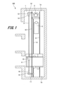
- FIG. 1 is a schematic diagram showing an elevator according to an embodiment of the present invention
- FIG. 1 is a plan view showing an elevator according to an embodiment.
- FIG. 2 is a perspective view showing an example of an installation example of a detector in an elevator according to an embodiment.
- 4(a) and 4(b) are perspective views showing another example of installation of a detector in an elevator according to the embodiment.
- 1 is an oblique view showing the configuration around a lower clip in an elevator detector in an example embodiment.
- FIG. 1 is an oblique view showing the configuration around a lower clip in an elevator detector in an example embodiment.
- FIG. 1 is an oblique view showing the configuration around a lower clip in an elevator detector in an example embodiment.
- FIG. 1 is a perspective view showing an elevator car and a sway suppression member according to an embodiment of the present invention
- 8A and 8B are front and plan views showing the operation of the elevator sway suppression member according to the embodiment
- 9A and 9B are front and plan views showing the operation of an elevator sway suppression member according to an embodiment of the present invention.
- FIG. 1 is a schematic diagram showing an elevator
- FIG. 2 is a plan view showing the elevator.
- the elevator 100 includes a hoist 3, a car 4 for carrying people and luggage, and a counterweight 5.
- the elevator 100 also includes car-side guide rails 6 and 7, and counterweight-side guide rails 8 and 9.
- the elevator 100 is equipped with a tape-shaped detection body 2 and a position detector 10 provided on the car 4 in order to detect the position of the car 4.
- the detection body 2 passes through an opening provided in the position detector 10.
- the position detector 10 detects the position of the car 4 by detecting the detection body 2.
- a magnetic tape is used as the detection body 2.
- a magnetic sensor that reads data from the detection body 2, which is a magnetic tape, is used as the position detector 10.
- an absolute position detector is used as the position detector 10.
- the detection body 2 is not limited to magnetic tape, but may be, for example, optical tape or any other type of tape-like detection body.
- the position detector 10 may be an optical sensor or any other type of position detector.
- the car 4 is formed in a hollow, roughly rectangular parallelepiped shape.
- the car 4 moves up and down in the elevator shaft 1 along the car side guide rails 6, 7.
- the car side guide rails 6, 7 are arranged on both sides of the car 4.
- the car side guide rails 6, 7 are also erected in the elevator shaft 1.
- the car 4 is also provided with a pulley (not shown).
- a main rope (not shown) is wound around this pulley.
- the main rope is wound around a sheave of the hoisting machine 3 and a pulley provided on the counterweight.
- the hoisting machine 3 is installed at the top of the elevator shaft 1 in the ascending/descending direction.
- the location at which the hoisting machine 3 is installed is not limited to the top of the elevator shaft 1, and it may be installed at the bottom of the elevator shaft 1.
- a machine room may be provided in the elevator shaft 1, and the hoisting machine 3 may be installed in this machine room.
- a counterweight 5 is disposed below the hoist 3.
- the counterweight 5 moves up and down the hoistway 1 along counterweight-side guide rails 8, 9.
- the counterweight-side guide rails 8, 9 are disposed on both sides of the counterweight 5.
- the counterweight-side guide rails 8, 9 are erected within the hoistway 1.
- the detector 2 extends from the top 1a to the bottom (pit) 1b of the elevator shaft 1 along the ascending and descending direction of the car 4.
- An upper bracket 12 is fixed to the upper part of the car-side guide rail 6, and a lower bracket 11 is fixed to the lower part of the car-side guide rail 6.
- An upper tape fixing part 13 is fixed to the upper bracket 12, and a lower tape fixing part 15 is fixed to the lower bracket 11.
- An upper clip 14 is provided at the upper end of the detection body 2.
- the upper clip 14 is fixed to the upper tape fixing part 13.
- a lower clip 16 is provided at the lower end of the detection body 2.
- the lower clip 16 is fixed to the lower tape fixing part 15. Note that although an example in which the upper tape fixing part 13 and the lower tape fixing part 15 are provided has been described, this is not limiting.
- the upper clip 14 may be fixed to the upper bracket 12, and the lower clip 16 may be fixed to the lower bracket 11.
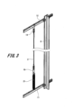
- Fig. 3 is a perspective view showing an example of installation of the detection body 2. In the example shown in Fig. 3, an installation example without providing the upper tape fixing part 13 and the lower tape fixing part 15 will be described.
- the upper clip 14 provided at the upper end of the detection body 2 is fixed to the upper bracket 12.
- the lower clip 16 provided at the lower end of the detection body 2 is provided with a spring 21.
- the upper end of the spring 21 is fixed to the lower clip 16, and the lower end of the spring 21 is fixed to the lower bracket 11.
- the detection body 2 is applied with tension by the spring force of the spring 21.
- FIG. 4(a) and 4(b) are diagrams showing other examples of installation of the detection body 2.
- an upper clip 14 provided at the upper end of the detection body 2 is fixed to an upper bracket 12 or an upper tape fixing part 13.
- a lower clip 16 provided at the lower end of the detection body 2 is inserted into a lower bracket 11 or a lower tape fixing part 15.
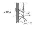
- Figures 5 and 6 are perspective views showing the configuration around the lower clip 16. Note that the example shown in Figures 5 and 6 shows an example in which the lower tape fixing portion 15 is not provided. As shown in Figures 5 and 6, an insertion hole 11a is formed in the lower bracket 11. The lower clip 16 is inserted into the insertion hole 11a. The lower end of the lower clip 16 protrudes from the lower end of the lower bracket 11. A hook 16a is formed at the lower end of the lower clip 16. When the hook 16a abuts against the lower bracket 11, it is possible to regulate the displacement of the detection body 2 in the contraction direction.
- a weight 22 is removably attached to the hook 16a.
- the load of the weight 22 is applied to the detection body 2 via the lower clip 16, and tension can be applied to the detection body 2.
- the position at which the lower bracket 11 is fixed to the car-side guide rail 6 is set based on the state in which the detection body 2 is stretched with the weight 22 hung on the lower clip 16.
- FIG. 7 is a perspective view showing the car 4 and the vibration suppressing member.
- a vibration suppressing member 31 and an open/close switch 30 are installed in the hoistway 1.
- the vibration suppressing member 31 is fixed to a bracket provided on the wall surface of the hoistway 1 or on the car-side guide rails 6, 7, etc.
- a plurality of vibration suppressing members 31 are installed at predetermined heights in the hoistway 1.
- the vibration suppressing members 31 are disposed at least in the middle of the hoistway 1.
- the vibration suppression member 31 is formed in a ring shape with a circular opening.
- the detection body 2 is inserted into the opening of the vibration suppression member 31.
- the vibration suppression member 31 surrounds the periphery of the detection body 2, preventing the detection body 2 from shaking significantly due to earthquakes or wind, and preventing the detection body 2 from getting caught on other components installed in the elevator shaft 1.
- the vibration suppression member 31 is not limited to a circular ring shape, and may be formed into various other shapes such as a square or hexagon. However, by forming the vibration suppression member 31 into a shape with a circular opening, it is possible to prevent the detection body 2 from getting caught on the corners of the vibration suppression member 31.
- the vibration suppression member 31 is preferably made of a soft material such as rubber or resin. This prevents the detection body 2 from being damaged when the detection body 2 comes into contact with the vibration suppression member 31, and also allows the vibration of the detection body 2 to be dampened by the vibration suppression member 31.
- the vibration suppression member 31 is also formed so that it can be opened and closed by a drive unit (not shown).
- the size of the opening when the vibration suppression member 31 is open is set to be larger than the size of the position detector 10.
- An open/close switch 30 is installed above and below the vibration suppression member 31 in the ascending/descending direction.
- the open/close switch 30 is provided with a roller 30a that represents a pressing portion.
- the open/close switch 30 is turned ON when the roller 30a is pressed by a cam 42, which will be described later.
- a cam 42 is installed on one surface of the car 4 that faces the roller 30a of the open/close switch 30.
- the cam 42 extends from the upper end to the lower end of the car 4.
- the cam 42 has an upper inclined surface 42a, a lower inclined surface 42b, and a straight surface 42c.
- the upper inclined surface 42a is disposed at the upper end of the car 4, and the lower inclined surface 42b is disposed at the lower end of the car 4.
- the straight surface 42c is disposed between the upper inclined surface 42a and the lower inclined surface 42b.
- the upper inclined surface 42a and the lower inclined surface 42b of the cam 42 protrude from the upper and lower ends of the car 4 in the vertical direction.
- the upper inclined surface 42a and the lower inclined surface 42b of the cam 42 are disposed at least above or below the position detector 10 in the vertical direction. Therefore, the upper inclined surface 42a or the lower inclined surface 42b of the cam 42 comes into contact with the roller 30a of the open/close switch 30 before the position detector 10 passes the sway suppression member 31.
- FIGS. 8A to 9B are diagrams illustrating the operation of the vibration suppression member 31. Note that Fig. 8A and Fig. 8B show a state before the car 4 passes through the vibration suppression member 31, and Fig. 9A and Fig. 9B show a state after the car 4 passes through the vibration suppression member 31.
- the roller 30a of the opening/closing switch 30 is not in contact with the cam 42 provided on the car 4. In this state, the opening/closing switch 30 is in the OFF state. As shown in FIG. 8B, when the opening/closing switch 30 is in the OFF state, the vibration suppression member 31 is closed. Therefore, the detection body 2 is surrounded by the vibration suppression member 31.
- the cam 42 moves away from the roller 30a of the open/close switch 30. This turns the open/close switch 30 OFF, and as shown in FIG. 8B, the vibration suppression member 31 closes.
- a mechanical switch operated by a roller 30a and a cam 42 is used as the opening/closing switch 30 for opening and closing the vibration suppression member 31, but this is not limited to this.
- Various types of switches such as a magnetic switch or an optical switch can be used as the opening/closing switch 30.
- the configuration of elevator 100 is not limited to the 2:1 roping elevator shown in Figure 1, but can be a 1:1 roping elevator, a hydraulic elevator, or any other type of elevator.
Landscapes
- Engineering & Computer Science (AREA)
- Automation & Control Theory (AREA)
- Computer Networks & Wireless Communication (AREA)
- Cage And Drive Apparatuses For Elevators (AREA)
Priority Applications (2)
| Application Number | Priority Date | Filing Date | Title |
|---|---|---|---|
| PCT/JP2023/023349 WO2024262014A1 (ja) | 2023-06-23 | 2023-06-23 | エレベーター |
| JP2025527389A JPWO2024262014A1 (https=) | 2023-06-23 | 2023-06-23 |
Applications Claiming Priority (1)
| Application Number | Priority Date | Filing Date | Title |
|---|---|---|---|
| PCT/JP2023/023349 WO2024262014A1 (ja) | 2023-06-23 | 2023-06-23 | エレベーター |
Publications (1)
| Publication Number | Publication Date |
|---|---|
| WO2024262014A1 true WO2024262014A1 (ja) | 2024-12-26 |
Family
ID=93935256
Family Applications (1)
| Application Number | Title | Priority Date | Filing Date |
|---|---|---|---|
| PCT/JP2023/023349 Ceased WO2024262014A1 (ja) | 2023-06-23 | 2023-06-23 | エレベーター |
Country Status (2)
| Country | Link |
|---|---|
| JP (1) | JPWO2024262014A1 (https=) |
| WO (1) | WO2024262014A1 (https=) |
Citations (5)
| Publication number | Priority date | Publication date | Assignee | Title |
|---|---|---|---|---|
| JPS5070661U (https=) * | 1973-10-31 | 1975-06-23 | ||
| JPS55123862A (en) * | 1979-03-16 | 1980-09-24 | Hitachi Ltd | Driver for elevator controller |
| JPS59165868U (ja) * | 1983-04-19 | 1984-11-07 | 三菱電機株式会社 | エレベ−タの位置検出装置 |
| JP2015113180A (ja) * | 2013-12-09 | 2015-06-22 | フジテック株式会社 | エレベータのかご位置検出装置の調整方法 |
| US20210078826A1 (en) * | 2019-09-12 | 2021-03-18 | Thyssenkrupp Elevator Corporation | Magnetic tape stabilizing systems |
-
2023
- 2023-06-23 JP JP2025527389A patent/JPWO2024262014A1/ja active Pending
- 2023-06-23 WO PCT/JP2023/023349 patent/WO2024262014A1/ja not_active Ceased
Patent Citations (5)
| Publication number | Priority date | Publication date | Assignee | Title |
|---|---|---|---|---|
| JPS5070661U (https=) * | 1973-10-31 | 1975-06-23 | ||
| JPS55123862A (en) * | 1979-03-16 | 1980-09-24 | Hitachi Ltd | Driver for elevator controller |
| JPS59165868U (ja) * | 1983-04-19 | 1984-11-07 | 三菱電機株式会社 | エレベ−タの位置検出装置 |
| JP2015113180A (ja) * | 2013-12-09 | 2015-06-22 | フジテック株式会社 | エレベータのかご位置検出装置の調整方法 |
| US20210078826A1 (en) * | 2019-09-12 | 2021-03-18 | Thyssenkrupp Elevator Corporation | Magnetic tape stabilizing systems |
Also Published As
| Publication number | Publication date |
|---|---|
| JPWO2024262014A1 (https=) | 2024-12-26 |
Similar Documents
| Publication | Publication Date | Title |
|---|---|---|
| CN104395220B (zh) | 电梯装置 | |
| KR20150095918A (ko) | 리프트의 설치 방법 | |
| JP5259379B2 (ja) | エレベーター装置 | |
| JP2003146555A (ja) | エレベータ | |
| JP6751373B2 (ja) | 非常停止装置及びエレベーター | |
| WO2024262014A1 (ja) | エレベーター | |
| JP2003118949A (ja) | エレベータ装置 | |
| JP2003276966A (ja) | エレベータ装置 | |
| JP4992281B2 (ja) | エレベータ装置 | |
| JP2010018373A (ja) | エレベーターのロープ制振装置 | |
| JP4706498B2 (ja) | エレベーター試験方法、その補助装置及びエレベーター装置 | |
| JP5396345B2 (ja) | エレベーターの乗りかご及びエレベーター装置 | |
| WO2024262016A1 (ja) | エレベーター | |
| JP6684473B2 (ja) | 複数の釣合い錘を備えるエレベータ | |
| JP4658067B2 (ja) | エレベータ装置 | |
| WO2024262015A1 (ja) | エレベーター | |
| JP4290731B2 (ja) | 釣合い重りレスエレベータ装置 | |
| JP4862296B2 (ja) | エレベータの検査方法 | |
| KR100645666B1 (ko) | 엘리베이터 장치 | |
| JPH1087228A (ja) | エレベータ | |
| CN109720959B (zh) | 调速器和电梯 | |
| JPH082844A (ja) | エレベーター釣合鎖用安全装置 | |
| JP4752268B2 (ja) | エレベータ装置 | |
| JP2019123610A (ja) | エレベーター装置 | |
| JP3438697B2 (ja) | 機械室レスエレベータ装置 |
Legal Events
| Date | Code | Title | Description |
|---|---|---|---|
| 121 | Ep: the epo has been informed by wipo that ep was designated in this application |
Ref document number: 23942445 Country of ref document: EP Kind code of ref document: A1 |
|
| ENP | Entry into the national phase |
Ref document number: 2025527389 Country of ref document: JP Kind code of ref document: A |
|
| WWE | Wipo information: entry into national phase |
Ref document number: 2025527389 Country of ref document: JP |
|
| NENP | Non-entry into the national phase |
Ref country code: DE |