WO2024261809A1 - 車両用駆動装置 - Google Patents
車両用駆動装置 Download PDFInfo
- Publication number
- WO2024261809A1 WO2024261809A1 PCT/JP2023/022582 JP2023022582W WO2024261809A1 WO 2024261809 A1 WO2024261809 A1 WO 2024261809A1 JP 2023022582 W JP2023022582 W JP 2023022582W WO 2024261809 A1 WO2024261809 A1 WO 2024261809A1
- Authority
- WO
- WIPO (PCT)
- Prior art keywords
- gear
- case
- lubricating oil
- drive device
- reduction gear
- Prior art date
- Legal status (The legal status is an assumption and is not a legal conclusion. Google has not performed a legal analysis and makes no representation as to the accuracy of the status listed.)
- Ceased
Links
Images



Classifications
-
- B—PERFORMING OPERATIONS; TRANSPORTING
- B60—VEHICLES IN GENERAL
- B60L—PROPULSION OF ELECTRICALLY-PROPELLED VEHICLES; SUPPLYING ELECTRIC POWER FOR AUXILIARY EQUIPMENT OF ELECTRICALLY-PROPELLED VEHICLES; ELECTRODYNAMIC BRAKE SYSTEMS FOR VEHICLES IN GENERAL; MAGNETIC SUSPENSION OR LEVITATION FOR VEHICLES; MONITORING OPERATING VARIABLES OF ELECTRICALLY-PROPELLED VEHICLES; ELECTRIC SAFETY DEVICES FOR ELECTRICALLY-PROPELLED VEHICLES
- B60L15/00—Methods, circuits, or devices for controlling the traction-motor speed of electrically-propelled vehicles
Definitions
- the present invention relates to a vehicle drive device that drives the wheels of a vehicle.
- the so-called in-wheel motor type has been proposed as a drive system for electric vehicles that use a motor as a drive source, in which the wheels are driven by a drive unit located inside the wheels.
- Vehicles that use this type of drive system have high acceleration response because the drive source is close to the wheels, and it is also possible to improve turning ability by independently controlling the drive force of the left and right wheels.
- Patent Document 1 describes a motor drive unit that reduces the output rotation of a motor using a high-speed reduction mechanism and a low-speed reduction mechanism, and uses the rotational torque of the motor amplified by this reduction to rotate and drive wheels.
- the high-speed reduction mechanism consists of a parallel shaft gear pair
- the low-speed reduction mechanism consists of a planetary gear reduction mechanism.
- the parallel shaft gear pair and the planetary gear reduction mechanism are housed in a reduction gear chamber surrounded by a motor case and a reduction gear case.
- An oil reservoir is provided at the bottom of the reduction gear chamber, with a high-speed reduction mechanism reservoir and a low-speed reduction mechanism reservoir separated by a partition plate.
- the parallel shaft gear pair is lubricated by the oil stored in the high-speed reduction mechanism reservoir
- the planetary gear reduction mechanism is lubricated by the oil stored in the low-speed reduction mechanism reservoir.
- In-wheel motor drive devices are required to be small because they are placed inside the wheels.
- the motor case and the reducer case are made larger by providing an oil reservoir at the bottom of the reducer chamber. Furthermore, making these cases larger causes the weight of the device to increase, which may lead to a decrease in fuel efficiency.
- the present invention aims to provide a vehicle drive unit that can be made small and lightweight.
- the present invention provides a vehicle drive device that drives the wheels of a vehicle and includes a motor, a reduction gear mechanism lubricated by lubricating oil, and a case that houses at least a portion of the reduction gear mechanism, the reduction gear mechanism having an input gear and an output gear, the output gear having a large diameter gear portion formed in a cylindrical shape with a larger diameter than the input gear, a shaft portion having an outer diameter smaller than the large diameter gear portion, and a disk portion provided between the large diameter gear portion and the shaft portion, the input gear meshes with the large diameter gear portion, a portion of the case is disposed inside the large diameter gear portion, and a storage portion for storing the lubricating oil is formed in the portion of the case.
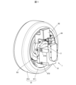
- FIG. 1 is a perspective view showing a drive unit, a wheel, a mounting member, a brake disc, and a brake unit according to an embodiment of the present invention.
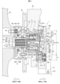
- FIG. 2 is a cross-sectional view of the drive device and its surroundings.
- FIG. 3 is a partially enlarged view of FIG.
- FIG. 4 is a perspective view showing a holding member and one support shaft member.
- FIG. 5 is a perspective view showing the connecting member.
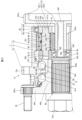
- FIG. 6 is a cross-sectional view of the drive unit, in which a cross section of the planetary gear mechanism perpendicular to the axial direction is seen from the vehicle inner side toward the vehicle outer side.
- FIG. 7 is a perspective cross-sectional view showing the outer member.
- FIG. 8A is a configuration diagram showing the case.
- FIG. 8A is a configuration diagram showing the case.
- FIG. 8B is a cross-sectional view taken along line AA of FIG. 8A.
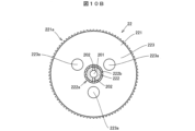
- FIG. FIG. 10A is a configuration diagram showing a reduction gear.
- FIG. 10B is a cross-sectional view of the reduction gear when the cross section of the shaft portion of the reduction gear is viewed from the vehicle outer side toward the vehicle inner side.
- FIG. 11 is a cross-sectional view showing a case and a reduction gear according to a modified example.
- FIG. 1 is a perspective view showing a drive unit 1 according to an embodiment of the present invention, a wheel 91 driven by the drive unit 1, a mounting member 92 to which the drive unit 1 is attached, a brake disc 93 that rotates integrally with the wheel 91, and a brake unit 94.
- the wheel 91 has a metal wheel 911 and a rubber tire 912 attached to the wheel 911.
- the mounting member 92 is connected to the body of the vehicle via a suspension arm, a shock absorber, and a suspension spring.
- the brake unit 94 generates a braking force by pressing brake pads against the brake disc 93.
- each part of the drive unit 1 is lubricated by lubricating oil sealed in the drive unit 1.
- lubricating oil sealed in the drive unit 1 The operation of each part of the drive unit 1 is lubricated by lubricating oil sealed in the drive unit 1.
- Fig. 2 is a cross-sectional view of the drive unit 1 and its surroundings.
- Fig. 3 is a partially enlarged view of Fig. 2.
- the top of the drawing corresponds to the top in the vertical direction
- the bottom of the drawing corresponds to the bottom in the vertical direction.
- “upper” and “lower” refer to the top and bottom in the vertical direction when the drive unit 1 is mounted on a vehicle.
- the mounting member 92 is formed with a mounting hole 920 for mounting the drive unit 1.
- the mounting hole 920 is a circular hole formed coaxially with the rotation axis O91 and passes through the mounting member 92.
- the side of the mounting member 92 facing the wheel 91 is referred to as the vehicle outer side, and the opposite side is referred to as the vehicle inner side.
- the driving device 1 includes, as functional components, a motor 10, a reduction gear mechanism 11 and a planetary gear mechanism 12 that reduce the speed of the output rotation of the motor 10, and a hub unit 13 that supports a wheel 91.
- the planetary gear mechanism 12 and the hub unit 13 are aligned along a rotation axis O91 and are arranged coaxially.
- the reduction gear mechanism 11 is provided between the motor 10 and the planetary gear mechanism 12.
- the reduction gear mechanism 11 functions as a primary reduction mechanism that reduces the speed of the output rotation of the motor 10.
- the planetary gear mechanism 12 has a plurality of planetary gears 4, and functions as a secondary reduction mechanism that further reduces the speed of the output rotation of the reduction gear mechanism 11.
- the main components of the drive unit 1 are a pinion gear 21 attached to the output shaft 101 of the motor 10, a large-diameter reduction gear 22 meshed with the pinion gear 21, a case 3 that houses at least a portion of the reduction gear mechanism 11, a number of planetary gears 4 that constitute the planetary gear mechanism 12, a carrier 5 that supports the number of planetary gears 4, an inner member 6 that rotates integrally with the carrier 5, an outer member 7 that is fitted and fixed in the mounting hole 920, a number of rolling elements 80 that are arranged between the inner member 6 and the outer member 7, and bearings 81 to 86.
- the motor 10 is an electric motor that generates torque to rotate the output shaft 101 by a driving current supplied from a control unit (not shown), and more specifically, is, for example, an embedded magnet type synchronous motor or a surface magnet type synchronous motor.
- the motor 10 is fixed to the case 3 by a number of bolts 872.
- the planetary gear mechanism 12 is composed of multiple planetary gears 4, a carrier 5, and part of the outer member 7.
- the hub unit 13 is composed of an inner member 6, multiple rolling elements 80, and part of the outer member 7.
- the planetary gear mechanism 12 further reduces the output rotation of the motor 10, which has been reduced by the reduction gear mechanism 11, and outputs it from the carrier 5 to the inner member 6.
- the inner member 6 is rotatably supported by the outer member 7 via the multiple rolling elements 80, and rotates integrally with the wheel 91.
- the pinion gear 21 is attached to the output shaft 101 of the motor 10 so as to be unable to rotate relative to the motor.
- An end of the pinion gear 21 on the vehicle inner side is rotatably supported by a bearing 81 held by the case 3.
- An end of the pinion gear 21 on the vehicle outer side is rotatably supported by a bearing 82 held by a mounting member 92.
- the pinion gear 21 has a small diameter gear portion 21a made of a spur gear between the bearings 81 and 82.
- a pitch circle diameter P21 of the small diameter gear portion 21a is shown.
- a rotation axis O21 of the pinion gear 21 is shown by a dashed line.
- the reduction gear 22 integrally includes a large diameter gear portion 221 formed in a cylindrical shape with a larger diameter than the pinion gear 102, a shaft portion 222 with an outer diameter smaller than that of the large diameter gear portion 221, and a disk portion 223 provided between the large diameter gear portion 221 and the shaft portion 222.
- the rotation axis O22 of the reduction gear 22 is indicated by a dashed line.
- the rotation axis O22 of the reduction gear 22 coincides with the rotation axis O91 of the wheel 91.
- the rotation axis O21 of the pinion gear 21 is parallel to the rotation axis O22 of the reduction gear 22.
- the pinion gear 21 is disposed below the rotation axis O22 of the reduction gear 22, and meshes with the large diameter gear portion 221 at the lower end of the reduction gear 22.
- the direction parallel to the rotation axis O22 of the reduction gear 22 is referred to as the axial direction.
- the shaft portion 222 extends in the axial direction from the inner peripheral end of the disk portion 223 toward the vehicle outer side, and is disposed in the center of the planetary gear mechanism 12.
- the plurality of planetary gears 4 are disposed on the outer periphery of the shaft portion 222.
- the shaft portion 222 is formed with a sun gear portion 222a that meshes with the plurality of planetary gears 4.
- the sun gear portion 222a is composed of helical teeth whose tooth traces are inclined with respect to the axial direction.
- the pitch circle diameter P222 of the sun gear portion 222a is formed smaller than the pitch circle diameter P221 of the large diameter gear portion 221a.
- the carrier 5 is configured to include a holding member 51 having multiple holding portions 50 that respectively hold the multiple planetary gears 4, a connecting member 52 that prevents the planetary gears 4 from slipping out of the holding portions 50 and connects the holding member 51 to the inner member 6, multiple support shaft members 53 that are arranged between the holding member 51 and the connecting member 52 and support the multiple planetary gears 4, and multiple bolts 54 that secure the holding member 51 to the connecting member 52.
- Figure 4 is a perspective view showing the retaining member 51 and one support shaft member 53.
- Figure 5 is a perspective view showing the connecting member 52.
- Figure 6 is a cross-sectional view of the drive unit 1, showing a cross section of the planetary gear mechanism 12 perpendicular to the axial direction, viewed from the vehicle inner side toward the vehicle outer side.
- Figure 7 is a perspective cross-sectional view showing the outer member 7.
- the retaining member 51 integrally comprises a disk-shaped base 511, a flange portion 512 provided at the end of the base 511 on the vehicle inner side, and a plurality of leg shaft portions 513 formed extending in the axial direction so as to protrude from the base 511 to the vehicle outer side.
- a through hole 511a is formed in the center of the base 511, into which the shaft portion 222 of the reduction gear 22 is inserted.
- the flange portion 512 is formed in an annular shape, protruding radially from the outer peripheral surface 511b of the base 511.
- the leg shafts 513 are provided at equal intervals along the circumferential direction of the base 511, and a retaining portion 50 is formed between the leg shafts 513.
- the planetary gear mechanism 12 has three planetary gears 4, and three leg shafts 513 are provided on the retaining member 51.
- a bolt insertion hole 513a is formed in each leg shaft 513 for inserting a bolt 54.
- the bolt 54 has a cylindrical insertion portion 541 that is inserted into the bolt insertion hole 513a, a head portion 542 that is larger in diameter than the insertion portion 541, and a male thread portion 543 that screws into the connecting member 52.
- the support shaft member 53 has a large diameter portion 531 that is inserted into the center of the planetary gear 4, and a pair of small diameter portions 532, 533 provided at both ends of the large diameter portion 531.
- the base portion 511 of the retaining member 51 is formed with a fitting hole 511c into which the small diameter portion 532 on the vehicle inner side of the pair of small diameter portions 532, 533 of the support shaft member 53 fits.
- the small diameter portion 533 on the vehicle outer side fits into a fitting hole 521a of the connecting member 52 described next.
- the connecting member 52 integrally comprises a disk-shaped cap portion 521 that closes the openings on the vehicle outer side of the multiple holding portions 50 to prevent the multiple planetary gears 4 from coming loose, a spline shaft portion 522 that extends from the center of the cap portion 521 to the vehicle outer side, and a male thread portion 523 provided at the end on the vehicle outer side.
- a recess 520 is formed in the center of the cap portion 521, recessed in the axial direction toward the vehicle outer side.
- the recess 520 houses a bearing 83 that supports the shaft portion 222 of the reduction gear 22, as shown in FIG. 2.
- the planetary gear 4 is supported on the outer periphery of the large diameter portion 531 of the support shaft member 53 via a bearing 84.
- the bearing 84 is a needle roller bearing, and has a number of needle rollers 841 and a retainer 842 that holds the number of needle rollers 841.
- two bearings 84 are arranged side by side in the axial direction between the large diameter portion 531 of the support shaft member 53 and the planetary gear 4.
- the outer member 7 extends around the outer periphery of the planetary gear mechanism 12.
- An internal gear portion 73 that meshes with multiple planetary gears 4 is provided on the inner periphery of the outer member 7. The configuration of the outer member 7 will be described in detail later.
- the inner member 6 is composed of a hub wheel 61 having a fitting hole 60 formed in the center into which the splined shaft portion 522 of the connecting member 52 is spline-fitted, and an inner ring 62 fitted onto the end of the hub wheel 61 on the vehicle inner side.
- a nut 873 is screwed onto the male threaded portion 523 of the connecting member 52 that protrudes from the fitting hole 60 to the vehicle outer side.
- the carrier 5 is connected to the inner member 6 so that it cannot rotate relative to the inner member 6 by spline-fitting the splined shaft portion 522 of the connecting member 52 into the fitting hole 60.
- the inner ring 62 is prevented from coming off the hub wheel 61 by abutting against the cap portion 521 of the connecting member 52.
- the inner ring 62 may also be prevented from coming off by crimping the end of the hub wheel 61 on the vehicle inner side.
- the rolling elements 80 are arranged in a double row between the inner member 6 and the outer member 7. More specifically, the rolling elements 80 form a first rolling element row 80A on the wheel 91 side and a second rolling element row 80B on the planetary gear mechanism 12 side.
- the rolling elements 80 of the first rolling element row 80A are held by a first retainer 801 and roll on a first inner raceway surface 61a formed on the hub wheel 61.
- the rolling elements 80 of the second rolling element row 80B are held by a second retainer 802 and roll on a second inner raceway surface 62a formed on the inner ring 62.
- the rolling elements 80 are spherical, but this is not limiting and the rolling elements 80 may be tapered rollers.
- the inner member 6 has a hub flange 601 to which the wheel 911 of the wheel 91 is attached, and a hub cylindrical portion 602 that is located on the inside of the first rolling element row 80A and the second rolling element row 80B.
- the hub flange 601 is part of the hub wheel 61.
- the hub cylindrical portion 602 is formed by a part of the hub wheel 61 and the inner ring 62.
- the first inner raceway surface 61a and the second inner raceway surface 62a are formed on the outer periphery of the hub cylindrical portion 602.
- a hub bolt 95 for mounting the brake disc 93 and the wheel 911 of the wheel 91 is fixed to the hub flange 601.
- the hub bolt 95 is press-fitted axially into a bolt hole 601a formed in the hub flange 601, and a hub nut 96 shown in FIG. 2 is screwed into the tip of the hub bolt.
- a female threaded hole may be formed in the hub flange 601, and the hub bolt may be screwed into this female threaded hole.
- the cylindrical portion 71 has an outer diameter slightly smaller than the inner diameter of the mounting hole 920, and is inserted into the mounting hole 920 from the vehicle outer side toward the vehicle inner side.
- a seal member 881 is disposed between the vehicle outer end of the cylindrical portion 71 and the hub wheel 61.
- the cylindrical portion 71 is formed with a first outer raceway surface 71a along which the multiple rolling elements 80 of the first rolling element row 80A roll, and a second outer raceway surface 71b along which the multiple rolling elements 80 of the second rolling element row 80B roll.
- the flange portion 72 is made up of a plurality of flange pieces 721, which are arranged radially so as to protrude outward from the cylindrical portion 71.
- the flange portion 72 may be arranged in an annular shape on the outer periphery of the cylindrical portion 71.
- the mounting member 92 has a threaded hole 92b formed at an open end surface 920a into which a bolt 97 for fixing the flange portion 72 is screwed.
- the open end surface 920a is the end surface of the mounting member 92 on the vehicle outer side around the opening of the mounting hole 920.
- the internal gear portion 73 is formed with a plurality of helical teeth 73a whose teeth are inclined relative to the axial direction.
- the internal gear portion 73 meshes with the helical teeth 4a of the plurality of planetary gears 4.
- the end of the cylindrical portion 71 on the vehicle inner side is formed with a bearing fitting portion 711 into which the bearing 85 is fitted.
- the bearing 85 is a ball bearing, and as shown in FIG. 3, has an outer ring 851, an inner ring 852, and a number of rolling elements 853 arranged between the outer ring 851 and the inner ring 852.
- the outer ring 851 is held in the bearing fitting portion 711 of the outer member 7.
- the inner ring 852 is arranged on the outer periphery of the base portion 511 of the retaining member 51, and its side surface on the vehicle inner side faces the flange portion 512 of the retaining member 51.
- Figure 8A is a diagram showing the surface of case 3 facing the mounting member 92.
- Figure 8B is a cross-sectional view of case 3 taken along line A-A in Figure 8A.
- Figure 9 is a perspective view of case 3.
- the shapes of holes and other parts formed inside case 3 are shown with dashed lines, and in Figure 8B, part of the reduction gear 22 that is combined with case 3 is shown with a two-dot chain line.
- Figure 9 shows case 3 as well as a shielding plate 891 that is assembled to case 3.
- the case 3 has an outer wall portion 31 that surrounds the pinion gear 21 and the large diameter gear portion 221 and disk portion 223 of the reduction gear 22, and a number of mounting pieces 32 formed to protrude outward from the outer wall portion 31.
- the flat surface of the outer wall portion 31 on the vehicle outer side serves as an abutment surface 31a that abuts against the mounting member 92.
- the mounting pieces 32 have bolt insertion holes 320 formed therein, into which bolts 871 are inserted to attach the case 3 to the mounting member 92.
- a part of the case 3 is disposed inside the large diameter gear portion 221 of the reduction gear 22.
- this part of the case 3 is referred to as a boss portion 33.
- the boss portion 33 is disk-shaped and centered on the rotation axis O22 of the reduction gear 22, and is formed to protrude toward the vehicle outer side beyond an opposing surface 3a of the case 3 that faces an end surface 221b of the large diameter gear portion 221 on the vehicle inner side.
- the opposing surface 3a is a plane that faces the vehicle outer side and is perpendicular to the axial direction.
- the end surface 33a of the boss portion 33 on the vehicle outer side faces the disk portion 223 of the reduction gear 22 in the axial direction with a small gap therebetween.
- a portion of the case 3 closer to the vehicle inner side than the opposing surface 3a is referred to as a base portion 34.
- the base portion 34 is formed with an accommodation hole 340 that accommodates the output shaft 101 and the bearing 81 of the motor 10 together with a part of the pinion gear 21.
- a seal member 882 for preventing leakage of the lubricating oil 90 is disposed in the accommodation hole 340.
- the pinion gear 21 is disposed vertically below the rotation axis O22 of the reduction gear 22, and the meshing portion between the small diameter gear portion 21a of the pinion gear 21 and the large diameter gear portion 221a of the large diameter gear portion 221 is bathed in the lubricating oil 90.
- a bearing 86 is disposed between the large diameter gear portion 221 and the boss portion 33, which supports the reduction gear 22 rotatably relative to the case 3.
- the bearing 86 has an outer ring 861 and an inner ring 862, and a number of rolling elements 863 disposed between the outer ring 861 and the inner ring 862.
- the outer ring 861 fits inside the large diameter gear portion 221.
- the boss portion 33 fits inside the inner ring 862.
- FIG. 10A is a diagram showing the surface of the reduction gear 22 facing the case 3.
- FIG. 10B is a cross-sectional view of the reduction gear 22, looking at the cross section of the shaft portion 222 of the reduction gear 22 from the vehicle outer side toward the vehicle inner side.
- the disk portion 223 of the reduction gear 22 is formed with a plurality of through holes 223a for allowing the lubricating oil 90 to flow in the axial direction. In this embodiment, three through holes 223a are formed at equal intervals in the circumferential direction.
- the shaft portion 222 of the reduction gear 22 is formed with an oil hole 201 along the rotation axis O22 for supplying the lubricating oil 90 to the vehicle outer side of the disk portion 223.
- the shaft portion 222 is also formed with a plurality of drain holes 202 communicating with the oil hole 201.
- the drain holes 202 extend in the radial direction of the shaft portion 222 and open to an outer circumferential surface 222b of the shaft portion 222.
- each discharge hole 202 opens into the outer peripheral surface 222b of the shaft portion 222 on the vehicle outer side of the sun gear portion 222a.
- the discharge hole 202 may open, for example, into the bottom surface of the teeth of the sun gear portion 222a.
- the lubricating oil 90 When the reduction gear 22 rotates, the lubricating oil 90 is discharged outward from the discharge hole 202 by centrifugal force.
- the lubricating oil 90 discharged from the discharge hole 202 lubricates each part of the planetary gear mechanism 12 and the hub unit 13. Specifically, the lubricating oil 90 is supplied to the meshing parts between the planetary gear 4 and the shaft part 222 of the reduction gear 22 and the internal gear part 73 of the outer member 7, the bearings 83, 84, and the multiple rolling elements 80.
- a seal member may be placed between the cap portion 521 of the connecting member 52 and the cylindrical portion 71 of the outer member 7, so that only the planetary gear mechanism 12 is lubricated by the lubricating oil 90 discharged from the discharge hole 202.
- grease with a higher viscosity than the lubricating oil 90 may be sealed between the hub cylindrical portion 602 and the cylindrical portion 71 of the outer member 7. In other words, it is sufficient that the lubricating oil 90 discharged from the discharge hole 202 is supplied to at least the planetary gear mechanism 12.
- the reservoir 301 By forming the reservoir 301 in the case 3, it is possible to increase the amount of lubricating oil 90 inside the drive unit 1, making it possible to suppress deterioration of the lubricating oil 90 even after long-term use, and also suppressing fluctuations in the height of the oil level 90a shown in FIG. 2 even if the lubricating oil 90 is scooped up by the rotation of the reduction gear 22.
- the reservoir 301 communicate with the breather chamber 302, when the temperature inside the case 3 and the outer member 7 in the drive unit 1 rises, the expanded air is released to the outside of the case 3 via the breather chamber 302 and the outside air communication hole 304, preventing a decrease in the sealing ability of the seal members 881, 882 due to an increase in internal pressure.
- the storage section 301 is formed closer to the motor 10 than the disk section 223 of the reduction gear 22 in the axial direction of the drive unit 1, and opens toward the disk section 223.
- the multiple through holes 223a of the disk section 223 are formed in a position where at least a portion of them are aligned in the axial direction and communicate with the storage section 301 when the reduction gear 22 rotates. With this configuration, the lubricating oil 90 can flow between the storage section 301 and the portion closer to the vehicle outer side than the disk section 223, via the multiple through holes 223a of the disk section 223.
- the storage section 301 is formed below the rotation axis O22 of the reduction gear 22, and has a partially circular shape when viewed from the vehicle outer side along the rotation axis O22 .
- the inner surface of the storage section 301 is formed by an arc surface 301a having an arc shape centered on the rotation axis O22 when viewed from the axial direction, a linear plane 301b connecting both ends of the arc surface 301a when viewed from the axial direction, and a bottom surface 301c perpendicular to the axial direction.
- the plane 301b is a horizontal plane.
- a portion of the storage portion 301 is formed in the boss portion 33, and another portion is formed in the base portion 34.
- the storage portion 301 is formed across the boss portion 33 and the base portion 34.
- the storage portion 301 may be formed only in the boss portion 33.
- the breather chamber 302 is formed so as to be recessed in a direction parallel to the rotation axis O22 of the reduction gear 22 from the end face 33a of the boss portion 33, which is the surface facing the disk portion 223 in the case 3.
- the opening of the breather chamber 302 on the disk portion 223 side is partially shielded by a shielding plate 891, which prevents the scattered lubricating oil 90 from directly hitting the outside air communication hole 304 and suppresses the intrusion of large bubbles into the breather chamber 302.
- the boss portion 33 has a stepped recess 311 formed around the opening of the breather chamber 302, and the shielding plate 891 is fitted into the stepped recess 311.
- the stepped recess 311 and the shielding plate 891 have a rounded rectangular shape as viewed along the rotation axis O22 .
- the shielding plate 891 may be fixed to the case 3 by press-fitting into the stepped recess 311, or may be fixed to the case 3 by, for example, welding, crimping, or bolting.
- the collection section 305 is a recess formed by cutting out a portion of the outer wall section 31 so as to open along the rotation direction of the reduction gear 22.
- a pair of collection sections 305 are formed in the case 3 so as to efficiently collect the lubricating oil 90 scooped up by the rotation of the reduction gear 22 in both the forward direction, which is the rotation direction of the reduction gear 22 when the vehicle moves forward, and the reverse direction, which is the rotation direction of the reduction gear 22 when the vehicle moves backward.
- the inner surface of the outer wall portion 31 includes an arc-shaped inner surface 31c centered on the rotation axis O22 of the reduction gear 22, a first inclined surface 31d extending from one end of the arc-shaped inner surface 31c toward one of the collection portions 305 and continuing to the inner surface 305a of the one collection portion 305, and a second inclined surface 31e extending from the other end of the arc-shaped inner surface 31c toward the other collection portion 305 and continuing to the inner surface 305a of the other collection portion 305.
- the arc-shaped inner surface 31c is formed above the pair of collection portions 305.
- the first and second inclined surfaces 31d, 31e are inclined downward toward the collection portion 305 side.
- the large diameter gear portion 221 scoops up the lubricating oil 90, and the scooped up lubricating oil 90 adheres to the arc-shaped inner surface 31c and the first and second inclined surfaces 31d, 31e.
- the adhered lubricating oil 90 flows down the first and second inclined surfaces 31d, 31e and into one of the pair of collection sections 305. As a result, the lubricating oil 90 is collected in the collection section 305.
- the lubricating oil 90 collected in the collection portion 305 is supplied to the oil hole 201 of the reduction gear 22 by an oil passage 306.
- the oil passage 306 is composed of an axial hole 306a aligned axially with the oil hole 201 of the reduction gear 22 along the rotation axis O22 of the reduction gear 22, and a pair of radial holes 306b that respectively communicate between the axial hole 306a and the pair of collection portions 305.
- the axial hole 306a faces the oil hole 201 of the reduction gear 22 at its end on the vehicle outer side, and communicates with a pair of radial holes 306b at its end on the vehicle inner side.
- the pair of radial holes 306b are formed from the outer peripheral surface 31b of the outer wall portion 31 toward the axial hole 306a.
- the end of the axial hole 306a on the outer peripheral surface 31b side of the outer wall portion 31 is blocked by a plug 893, as shown in FIG. 9.
- the lubricating oil 90 supplied to the oil hole 201 of the reduction gear 22 is discharged from the discharge hole 202 as described above to lubricate each part of the planetary gear mechanism 12, for example flowing downward between the carrier 5 and the cylindrical part 71 of the outer member 7, and is scooped up again by the rotation of the reduction gear 22.
- the reservoir 301 is formed in the boss 33, which is a part of the case 3 arranged inside the large diameter gear portion 221 of the reduction gear 22, so that it is possible to increase the amount of lubricating oil 90 in the drive device 1 while suppressing an increase in size of the case 3.
- the dead space inside the large diameter gear portion 221 as part of the reservoir 301 it is possible to reduce the size and weight of the drive device 1.
- the breather chamber 302 is formed above the reservoir 301, so that it is possible to prevent foreign matter from being mixed into the lubricating oil 90 while preventing an increase in pressure inside the case 3 and the outer member 7.
- a modified example of the drive device will be described with reference to Fig. 11.
- the shapes of the case 3 and the reduction gear 22 are different from those of the above embodiment, but the rest are configured similarly to the above embodiment.
- Fig. 11 shows the case 3 and reduction gear mechanism 11, as well as the motor 10, related to the modified example, and does not show other members.
- the same reference numerals as those in Fig. 2 are used for members common to the above embodiment.
- the outer ring 861 of the bearing 86 is fitted to the inside of the large diameter gear portion 221 and rotates with the reduction gear 22, and the boss portion 33 is fitted to the inside of the inner ring 862 of the bearing 86.
- the outer ring 861 of the bearing 86 is fixed to the boss portion 33, and the inner ring 862 of the bearing 86 is configured to rotate with the reduction gear 22.
- the reduction gear 22 has a large diameter gear portion 221, a shaft portion 222, a disk portion 223, and an annular protrusion 224 that is fitted to the inside of the inner ring 862.
- the annular protrusion 224 protrudes in the axial direction from the surface 223b of the disk portion 223 that faces the boss portion 33 toward the vehicle inner side.
- the boss portion 33 of the case 3 is formed with an annular recess 330 centered on the rotation axis O22 of the reduction gear 22.
- the bearing 86 and the annular protrusion 224 of the reduction gear 22 are housed in the recess 330.
- the outer ring 861 is fitted into the inner peripheral surface 330a on the outer diameter side of the recess 330.
- a gap is formed between the outer peripheral surface 330b on the inner diameter side of the recess 330 and the annular protrusion 224.
- This modification also provides the same effects as the above embodiment.
- the present invention can be modified as appropriate by omitting some components or adding or substituting components without departing from the spirit of the invention.
- a case has been described in which the shaft portion 222 of the reduction gear 22 constituting the reduction gear mechanism 11 protrudes from the case 3 and is housed in the outer member 7, but this is not limiting, and the entire reduction gear 22 may be housed in the case 3.
- the case 3 houses at least a portion of the reduction gear mechanism 11.
Landscapes
- Engineering & Computer Science (AREA)
- Power Engineering (AREA)
- Transportation (AREA)
- Mechanical Engineering (AREA)
- General Details Of Gearings (AREA)
Priority Applications (3)
| Application Number | Priority Date | Filing Date | Title |
|---|---|---|---|
| JP2025527221A JPWO2024261809A1 (https=) | 2023-06-19 | 2023-06-19 | |
| CN202380099312.XA CN121358626A (zh) | 2023-06-19 | 2023-06-19 | 车辆用驱动装置 |
| PCT/JP2023/022582 WO2024261809A1 (ja) | 2023-06-19 | 2023-06-19 | 車両用駆動装置 |
Applications Claiming Priority (1)
| Application Number | Priority Date | Filing Date | Title |
|---|---|---|---|
| PCT/JP2023/022582 WO2024261809A1 (ja) | 2023-06-19 | 2023-06-19 | 車両用駆動装置 |
Publications (1)
| Publication Number | Publication Date |
|---|---|
| WO2024261809A1 true WO2024261809A1 (ja) | 2024-12-26 |
Family
ID=93935168
Family Applications (1)
| Application Number | Title | Priority Date | Filing Date |
|---|---|---|---|
| PCT/JP2023/022582 Ceased WO2024261809A1 (ja) | 2023-06-19 | 2023-06-19 | 車両用駆動装置 |
Country Status (3)
| Country | Link |
|---|---|
| JP (1) | JPWO2024261809A1 (https=) |
| CN (1) | CN121358626A (https=) |
| WO (1) | WO2024261809A1 (https=) |
Citations (3)
| Publication number | Priority date | Publication date | Assignee | Title |
|---|---|---|---|---|
| JP2012239369A (ja) * | 2011-04-27 | 2012-12-06 | Nissan Motor Co Ltd | 車両用インホイールモータユニットの潤滑制御装置 |
| WO2013054385A1 (ja) * | 2011-10-14 | 2013-04-18 | トヨタ自動車株式会社 | 動力伝達装置 |
| JP2015132315A (ja) * | 2014-01-10 | 2015-07-23 | 日産自動車株式会社 | モータ駆動ユニットの油送構造 |
-
2023
- 2023-06-19 WO PCT/JP2023/022582 patent/WO2024261809A1/ja not_active Ceased
- 2023-06-19 CN CN202380099312.XA patent/CN121358626A/zh active Pending
- 2023-06-19 JP JP2025527221A patent/JPWO2024261809A1/ja active Pending
Patent Citations (3)
| Publication number | Priority date | Publication date | Assignee | Title |
|---|---|---|---|---|
| JP2012239369A (ja) * | 2011-04-27 | 2012-12-06 | Nissan Motor Co Ltd | 車両用インホイールモータユニットの潤滑制御装置 |
| WO2013054385A1 (ja) * | 2011-10-14 | 2013-04-18 | トヨタ自動車株式会社 | 動力伝達装置 |
| JP2015132315A (ja) * | 2014-01-10 | 2015-07-23 | 日産自動車株式会社 | モータ駆動ユニットの油送構造 |
Also Published As
| Publication number | Publication date |
|---|---|
| CN121358626A (zh) | 2026-01-16 |
| JPWO2024261809A1 (https=) | 2024-12-26 |
Similar Documents
| Publication | Publication Date | Title |
|---|---|---|
| US8932170B2 (en) | Planetary gear device | |
| CN102235482B (zh) | 差动齿轮单元的润滑结构 | |
| RU2667024C1 (ru) | Внутриколесный узел с двигателем | |
| JP2009012523A (ja) | 車輪駆動装置 | |
| RU2501646C2 (ru) | Уплотнительное устройство для камеры зубчатой передачи | |
| CN101965467A (zh) | 轮毂电动机驱动装置 | |
| US20180294692A1 (en) | In-wheel motor driving device | |
| JP2008184111A (ja) | 車輪駆動装置 | |
| CN113251110A (zh) | 纯电动车用二级减速器带差速器总成 | |
| JP2013040665A (ja) | 遊星歯車装置 | |
| WO2022246054A1 (en) | Electric drive module for driving a vehicle wheel | |
| KR102741908B1 (ko) | 기어 시스템 | |
| US20160138702A1 (en) | Differential device | |
| JP6647930B2 (ja) | インホイールモータ駆動装置 | |
| JP2013164139A (ja) | インホイールモータ駆動装置 | |
| JP2022540239A (ja) | 自動車用の電動式の駆動ユニット | |
| CN219888692U (zh) | 电驱动车差速器的油冷润滑结构 | |
| WO2024261809A1 (ja) | 車両用駆動装置 | |
| WO2019054381A1 (ja) | 車両駆動装置 | |
| CN206159454U (zh) | 新型多档齿轮箱行星排固定及润滑结构 | |
| CN211231449U (zh) | 一种大扭矩行星减速机 | |
| WO2012114847A1 (ja) | 遊星歯車装置 | |
| JP2011106610A (ja) | 減速機のスラストブシュ潤滑構造 | |
| WO2019177104A1 (ja) | 車両駆動装置 | |
| CN216200194U (zh) | 一种减速机、电驱动总成及搅拌车 |
Legal Events
| Date | Code | Title | Description |
|---|---|---|---|
| 121 | Ep: the epo has been informed by wipo that ep was designated in this application |
Ref document number: 23942248 Country of ref document: EP Kind code of ref document: A1 |
|
| ENP | Entry into the national phase |
Ref document number: 2025527221 Country of ref document: JP Kind code of ref document: A |