WO2024257982A1 - 폐이차전지 양극재 재생 용액 및 이를 이용한 양극재 재생 방법 - Google Patents
폐이차전지 양극재 재생 용액 및 이를 이용한 양극재 재생 방법 Download PDFInfo
- Publication number
- WO2024257982A1 WO2024257982A1 PCT/KR2024/000926 KR2024000926W WO2024257982A1 WO 2024257982 A1 WO2024257982 A1 WO 2024257982A1 KR 2024000926 W KR2024000926 W KR 2024000926W WO 2024257982 A1 WO2024257982 A1 WO 2024257982A1
- Authority
- WO
- WIPO (PCT)
- Prior art keywords
- lithium
- cathode material
- ether
- secondary battery
- solution
- Prior art date
- Legal status (The legal status is an assumption and is not a legal conclusion. Google has not performed a legal analysis and makes no representation as to the accuracy of the status listed.)
- Ceased
Links
Images








Classifications
-
- H—ELECTRICITY
- H01—ELECTRIC ELEMENTS
- H01M—PROCESSES OR MEANS, e.g. BATTERIES, FOR THE DIRECT CONVERSION OF CHEMICAL ENERGY INTO ELECTRICAL ENERGY
- H01M4/00—Electrodes
- H01M4/02—Electrodes composed of, or comprising, active material
- H01M4/04—Processes of manufacture in general
- H01M4/0402—Methods of deposition of the material
- H01M4/0416—Methods of deposition of the material involving impregnation with a solution, dispersion, paste or dry powder
-
- H—ELECTRICITY
- H01—ELECTRIC ELEMENTS
- H01M—PROCESSES OR MEANS, e.g. BATTERIES, FOR THE DIRECT CONVERSION OF CHEMICAL ENERGY INTO ELECTRICAL ENERGY
- H01M10/00—Secondary cells; Manufacture thereof
- H01M10/54—Reclaiming serviceable parts of waste accumulators
-
- H—ELECTRICITY
- H01—ELECTRIC ELEMENTS
- H01M—PROCESSES OR MEANS, e.g. BATTERIES, FOR THE DIRECT CONVERSION OF CHEMICAL ENERGY INTO ELECTRICAL ENERGY
- H01M4/00—Electrodes
- H01M4/02—Electrodes composed of, or comprising, active material
- H01M4/36—Selection of substances as active materials, active masses, active liquids
- H01M4/48—Selection of substances as active materials, active masses, active liquids of inorganic oxides or hydroxides
- H01M4/50—Selection of substances as active materials, active masses, active liquids of inorganic oxides or hydroxides of manganese
- H01M4/505—Selection of substances as active materials, active masses, active liquids of inorganic oxides or hydroxides of manganese of mixed oxides or hydroxides containing manganese for inserting or intercalating light metals, e.g. LiMn2O4 or LiMn2OxFy
-
- H—ELECTRICITY
- H01—ELECTRIC ELEMENTS
- H01M—PROCESSES OR MEANS, e.g. BATTERIES, FOR THE DIRECT CONVERSION OF CHEMICAL ENERGY INTO ELECTRICAL ENERGY
- H01M4/00—Electrodes
- H01M4/02—Electrodes composed of, or comprising, active material
- H01M4/36—Selection of substances as active materials, active masses, active liquids
- H01M4/48—Selection of substances as active materials, active masses, active liquids of inorganic oxides or hydroxides
- H01M4/52—Selection of substances as active materials, active masses, active liquids of inorganic oxides or hydroxides of nickel, cobalt or iron
- H01M4/525—Selection of substances as active materials, active masses, active liquids of inorganic oxides or hydroxides of nickel, cobalt or iron of mixed oxides or hydroxides containing iron, cobalt or nickel for inserting or intercalating light metals, e.g. LiNiO2, LiCoO2 or LiCoOxFy
-
- H—ELECTRICITY
- H01—ELECTRIC ELEMENTS
- H01M—PROCESSES OR MEANS, e.g. BATTERIES, FOR THE DIRECT CONVERSION OF CHEMICAL ENERGY INTO ELECTRICAL ENERGY
- H01M4/00—Electrodes
- H01M4/02—Electrodes composed of, or comprising, active material
- H01M2004/026—Electrodes composed of, or comprising, active material characterised by the polarity
- H01M2004/028—Positive electrodes
-
- Y—GENERAL TAGGING OF NEW TECHNOLOGICAL DEVELOPMENTS; GENERAL TAGGING OF CROSS-SECTIONAL TECHNOLOGIES SPANNING OVER SEVERAL SECTIONS OF THE IPC; TECHNICAL SUBJECTS COVERED BY FORMER USPC CROSS-REFERENCE ART COLLECTIONS [XRACs] AND DIGESTS
- Y02—TECHNOLOGIES OR APPLICATIONS FOR MITIGATION OR ADAPTATION AGAINST CLIMATE CHANGE
- Y02E—REDUCTION OF GREENHOUSE GAS [GHG] EMISSIONS, RELATED TO ENERGY GENERATION, TRANSMISSION OR DISTRIBUTION
- Y02E60/00—Enabling technologies; Technologies with a potential or indirect contribution to GHG emissions mitigation
- Y02E60/10—Energy storage using batteries
-
- Y—GENERAL TAGGING OF NEW TECHNOLOGICAL DEVELOPMENTS; GENERAL TAGGING OF CROSS-SECTIONAL TECHNOLOGIES SPANNING OVER SEVERAL SECTIONS OF THE IPC; TECHNICAL SUBJECTS COVERED BY FORMER USPC CROSS-REFERENCE ART COLLECTIONS [XRACs] AND DIGESTS
- Y02—TECHNOLOGIES OR APPLICATIONS FOR MITIGATION OR ADAPTATION AGAINST CLIMATE CHANGE
- Y02W—CLIMATE CHANGE MITIGATION TECHNOLOGIES RELATED TO WASTEWATER TREATMENT OR WASTE MANAGEMENT
- Y02W30/00—Technologies for solid waste management
- Y02W30/50—Reuse, recycling or recovery technologies
- Y02W30/84—Recycling of batteries or fuel cells
Definitions
- the present invention relates to a solution for regenerating a cathode material of a waste secondary battery and a recycled secondary battery using the same.
- Lithium secondary batteries have the advantages of high energy density, light weight, high output while maintaining stable discharge characteristics, and stability over a wide range of temperatures, and are widely used in small home appliances and precision devices today. Recently, the use of medium- to large-sized lithium secondary batteries has also been rapidly increasing.
- the direct recycling (or cathode regeneration) method has the advantage of being able to quickly obtain new positive electrode materials from spent batteries because it can regenerate the active material with relatively little energy and a simple process while maintaining the particle shape of the spent positive electrode material.
- the direct recycling methods reported so far include the solid-state reaction method, the hydrothermal synthesis method, and the eutectic salt synthesis method.
- each of them requires a precise lithium composition analysis that is expensive, requires a high reaction temperature of hundreds of degrees and high pressure conditions, or requires an inert atmosphere without oxygen, making large-scale processes difficult and expensive, which is an obstacle to commercialization.
- the inventor of the present invention completed the present invention in order to solve the problems of the existing positive electrode active material recycling method as described above.
- the present invention has been made to solve the above problems, and the purpose of the present invention is to provide a solution for regenerating a waste secondary battery cathode material, which can easily obtain a regenerated cathode material with recovered lithium composition by supporting a cathode or cathode active material from which lithium has been completely or partially desorbed at room temperature and pressure for a certain period of time, without a long-term post-heat treatment process or the use of bases, toxic gases, or lithium metal.
- the present invention aims to provide a method for regenerating a waste secondary battery cathode material by utilizing the regeneration solution, or to provide a method for recycling the regeneration solution by simply mixing the used regeneration solution with a reducing substance including lithium after regeneration of the cathode material.
- a p-type redox molecule a solvent and a lithium salt are included,
- a regeneration solution for a waste secondary battery cathode material wherein the reduction potential of the p-type redox molecule is 1.55 V or more and 3.7 V or less vs. lithium (vs. Li/Li + ).
- Step (S3) of recovering and washing the loaded cathode material from the solution
- a method for regenerating a waste secondary battery cathode material wherein the reduction potential of the p-type redox molecule is 1.55 V or more and 3.7 V or less vs. lithium (vs. Li/Li + ).
- a cathode material regenerated with the regeneration solution is provided.
- a method for recycling a regeneration solution wherein the reducing material including lithium is at least one selected from the group consisting of Li 2 CO 3 , Li 2 O 2 , LiO 2 , LiO, Li 2 O and Li 2 S.
- a regeneration solution according to one embodiment of the present invention has the advantage of being highly mass-producible because it is stable without reactivity in a general environment under room temperature, pressure, and dry air, and can recover a desired amount of lithium composition based on high reproducibility even without information on the lithium composition of a spent positive electrode, and can be reused after post-processing the used regeneration solution, thereby being highly economical.
- Figure 1 is a schematic diagram of a regeneration solution and a cathode regeneration technology using the same according to one embodiment of the present invention.
- FIG. 2 is a diagram illustrating the principle of a bipolar regeneration technology according to one embodiment of the present invention.
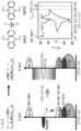
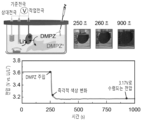
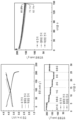
- FIG. 3 is a drawing showing electrochemical detection of a positive electrode lithium recovery reaction in a positive electrode regeneration technology according to one embodiment of the present invention.
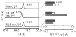
- FIG. 4 is a diagram showing the recovery of the cathode material lattice constant through a cathode lithium recovery reaction according to one embodiment of the present invention.
- FIG. 5 is a diagram showing the recovery of positive electrode nickel oxidation number through a positive electrode lithium recovery reaction according to one embodiment of the present invention.
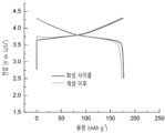
- Figure 6 is a diagram showing the results of evaluating the electrochemical characteristics of a regenerative cathode according to the lithium salt concentration and the presence or absence of p-type redox molecules.
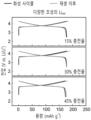
- Figure 7 is a drawing showing the results of evaluating the electrochemical characteristics of a regenerated cathode according to the composition of lithium in the waste cathode material.
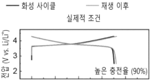
- Figure 8 is a drawing showing the results of evaluating the electrochemical characteristics of a regenerated cathode according to the lithium composition (highly desorbed state) of the waste cathode material.
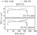
- Figure 9 is a drawing showing the results of evaluating the electrochemical characteristics of a regenerative anode according to the type of solvent under dry air.
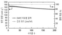
- FIG. 10 is a drawing showing the results of evaluating the life characteristics of a positive electrode regenerated through a positive electrode lithium recovery reaction according to one embodiment of the present invention.
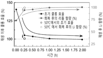
- Figure 11 is a diagram analyzing the degree of lithium recovery according to the positive electrode regeneration reaction time and temperature.
- FIG. 12 is a drawing showing the results of evaluating the life characteristics of an NMC 811 cathode regenerated through a cathode lithium recovery reaction according to one embodiment of the present invention.
- Figure 13 is a diagram showing the results of analyzing the redox voltage by applying DPPD or DBB as a p-type redox molecule.
- Figure 14 is a diagram showing the results of evaluating the change in Coulombic efficiency by applying DPPD or DBB as a p-type redox molecule.
- Figure 15 is a drawing showing the results of evaluating the change in Coulombic efficiency by applying LiPF 6 as a lithium salt in a regeneration solution.
- FIG. 16 is a diagram schematically showing a recycling process after use of a regeneration solution according to one embodiment of the present invention.
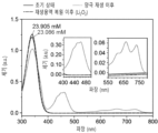
- Figure 17 is a drawing showing the results of verifying the recycling reaction after use of the regeneration solution.
- FIG. 18 is a diagram showing a cycle of regeneration of waste cathode material using a regeneration solution according to one embodiment of the present invention, followed by recycling of the regeneration solution and regeneration of cathode material using the same.
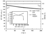
- Figure 19 is a diagram showing the results of a life test of an NMC 622 electrode regenerated using a recycled regeneration solution.
- Figure 20 is a drawing showing the results of evaluating the electrochemical characteristics of the NMC 622 electrode regenerated using a ferrocene-based regeneration solution prepared in various solvents (dioxolane (1,3-dioxolane; DOL), dimethyl carbonate (DMC), 2-methylhydrofuran (2meTHF), acetonitrile (ACN), and dimethylformamide (N,N-dimethylformamide; DMF)).
- solvents dioxolane (1,3-dioxolane; DOL
- DMC dimethyl carbonate
- 2meTHF 2-methylhydrofuran
- ACN acetonitrile
- DMF dimethylformamide
- a p-type redox molecule a solvent and a lithium salt are included,
- a solution for regenerating a waste secondary battery cathode material wherein the reduction potential of the p-type redox molecule is 1.55 V or more and 3.7 V or less vs. lithium (vs Li/Li + ).
- the redox molecules When the lithium ions of the lithium salt, the p-type redox molecules, and the cathode from which some lithium ions have been released are mixed with each other, the redox molecules are oxidized, the cathode active material is reduced through a thermodynamic spontaneous reaction, and lithium ions and electrons move from the p-type redox molecules to the cathode active material.
- lithium can be inserted into the cathode material from which lithium ions of a waste secondary battery have been desorbed.
- the p-type redox molecule for inducing a spontaneous reaction must i) be able to be oxidized in a neutral state and exist in the form of a cation, ii) have a redox potential lower than the general charge start voltage of the cathode (3.7 V for NMC), and iii) have a higher reduction potential than the reduction potential that causes material deterioration due to excessive lithium insertion (Mn 3+ /Mn 4+ reduction potential of 1.55 V for NMC).
- the types of p-type redox molecules satisfying all of the conditions of the above i) to iii) may include molecules such as N,N'-substituted phenazine, phenoxazine, phenylamine, phenothiazine, carbazole, phenylamine, thianthrene, dibenzodioxin, viologen, nitroxide radical compound, polyaniline, polythiophene, polytriphenylamine, polydiphenylamine, ferrocene, and manganocene, and the molecules may include an alkyl group (-R) having 1 to 5 carbon atoms, a hydroxyl group (-OH), It may be substituted with one or more of an amine group (-NH 2 ), a phenyl group (-Ph), a benzoate group (-BzO), an acetyl group (-CH 3 CO), a carboxyl group (-COOH), and a benzoyl group (-C
- the solvent included in the regeneration solution may include a cyclic ether solvent, a linear ether solvent, a carbonate (ester) solvent, acetonitrile, dimethyl sulfoxide (DMSO), dimethylformamide (DMF), dimethyl acetamide (DMAC), water (H 2 O), and the like.
- the above solvents are stable at the intended positive electrode operating potential, can dissolve lithium salts and redox molecules, and do not cause side reactions.
- cyclic ether solvents may include tetrahydropyran, dioxolane, methyldioxolane, dimethyldioxolane, vinyldioxolane, methoxydioxolane, ethylmethyldioxolane, oxane, dioxane, trioxane, tetrahydrofuran, methyltetrahydrofuran, dimethyltetrahydrofuran, dimethoxytetrahydrofuran, ethoxytetrahydrofuran, ethyltetrahydrofuran, methyltetrahydropyran, dimethyltetrahydropyran, dihydropyran, tetrahydropyran, hexamethylene oxide, furan, dihydrofuran, dimethoxybenzene, dimethyloxetane, and the like.
- linear ether solvents may include dimethyl ether, diethyl ether, ethyl methyl ether, ethyl propyl ether, dipropyl ether, diisopropyl ether, dibutyl ether, diisobutyl ether, ethyl tertbutyl ether, dimethoxymethane, trimethoxymethane, dimethoxyethane, diethoxyethane, dimethoxypropane, diethylene glycol dimethyl ether, diethylene glycol ethyl methyl ether, diethylene glycol isopropyl methyl ether, diethylene glycol butyl methyl ether, diethylene glycol diethyl ether, diethylene glycol tertbutyl ethyl ether, triethylene glycol dimethyl ether, tetraethylene glycol dimethyl ether, ethylene glycol ethyl methyl ether, ethylene glycol divinyl ether, diethylene glycol glycol
- the lithium salt included in the regeneration solution according to one embodiment of the present invention is not particularly limited as long as it is a substance that can be dissolved in the solvent and provide lithium ions to the cathode material from which lithium ions have been desorbed, but specifically, it may include lithium bistrifluoromethanesulfonylimide (LiTFSI), lithium hexafluorophosphate (LiPF 6 ), lithium bisfluorosulfonylimide (LiFSI), lithium trifluoromethanesulfonate (LiTf), lithium trifluoromethanesulfone (LiOTF), lithium tetrafluoroborate (LiBF 4 ), lithium perchlorate (LiClO 4 ), lithium hexafluoroarsenate (LiAsF 6 ), lithium difluorooxalatomolate (LiDFOB), lithium bisoxalateborate (LiBOB), lithium chloride (LiCl), lithium nitrate (Li
- Types of cathode materials into which lithium ions can be inserted through the regeneration solution according to one embodiment of the present invention include Li[NiCoMn]O 2 , LiCoO 2 , Li[NiCoAl]O 2 , Li[NiCoMnAl]O 2 , doped-Li[NiCoMn][M]O 2 , LiMn 2 O 4 , LiFePO 4 , Li[FeMn]PO 4 , LiNi 0.5 Mn 1.5 O 4 , etc.
- the cathode materials may include Li[NiCoMn]O 2 (NMC) having a charge start voltage of about 3.7 V, LiCoO 2 (LCO) having a charge start voltage of about 3.9 V, Li[NiCoAl]O 2 (NCA) having a charge start voltage of about 3.6 V, LiFePO 4 (LFP) having a charge start voltage of about 3.4 V, and the like.
- a step (S1) of preparing a regeneration solution by dissolving a lithium salt and a p-type redox molecule in a solvent a step (S1) of preparing a regeneration solution by dissolving a lithium salt and a p-type redox molecule in a solvent
- Step (S3) of recovering and washing the loaded cathode material from the solution
- a method for regenerating a waste secondary battery cathode material wherein the reduction potential of the p-type redox molecule is 1.55 V or more and 3.7 V or less vs. lithium (vs Li/Li + ).
- the method for regenerating a cathode material has the advantages of high mass productivity and reproducibility in that a reaction easily and stably occurs simply by supporting the cathode material in a solution without using separate lithium metal and without quantitative determination of the lithium composition, and that the lithium insertion reaction occurs only until the potential of the cathode material reaches the oxidation/reduction potential of a p-type redox molecule without excessive lithium insertion.
- the positive electrode material is recovered and washed.
- the washing process can be performed using the same type of solvent as that used in the previous regeneration solution. Through this, residual lithium salts and p-type redox molecules such as DMPZ present in the regenerated positive electrode material can be removed, and after a drying process, the regenerated positive electrode material can be used for electrode manufacturing.
- a regeneration solution used for regenerating a cathode material is mixed with a reducing substance including lithium to reduce redox molecules, and is regenerated through a filtration process, thereby providing a recycling method that can be used again as a regeneration solution.
- the lithium-containing reducing material used may be Li 2 CO 3 , Li 2 O 2 , LiO 2 , LiO, Li 2 O, Li 2 S, etc.
- a regeneration solution was prepared by dissolving lithium bistrifluoromethanesulfonylimide (LiTFSI) and 5,10-dihydro-5,10-dimethylphenazine (DMPZ) in 1,2-dimethoxyethane (DME) solvent.
- LiTFSI lithium bistrifluoromethanesulfonylimide
- DMPZ 5,10-dihydro-5,10-dimethylphenazine
- DME 1,2-dimethoxyethane
- Test Example 1 Electrochemical Detection of Positive Lithium Recovery Reaction ( Figure 3)
- the open circuit voltage of the working electrode converges to 3.17 V, which is a value close to the redox voltage of DMPZ. It was confirmed through the change in color and the convergent voltage value that lithium was inserted into the NMC active material by the oxidation of DMPZ, thereby lowering the voltage of the working electrode.
- Test Example 2 Observation of the recovery of the cathode material lattice constant and the cathode material nickel oxidation number through the cathode lithium recovery reaction (Fig. 4 and Fig. 5)
- X-Ray Diffraction (XRD) analysis was performed on the fresh NMC 622 electrode, the NMC 622 electrode charged to 30% of its reversible capacity after two cycles of charge/discharge, and the electrode regenerated by soaking in a 140 mM DMPZ + LiTFSI regeneration solution with 10 times the lithium deficiency amount for 2 hours in an argon atmosphere at room temperature after 30% charge.
- XRD X-Ray Diffraction
- the (003) peak of the new electrode is located at the highest angle of 18.64 degrees, and after 30% charging, it shifts to a smaller angle and the peak is found at 18.49 degrees, and after regeneration, a peak is observed at 18.65 degrees, similar to the new electrode.
- the (003) peak position of the 30% charged electrode is restored to a level similar to that of a new NMC 622 electrode after regeneration, indicating that lithium is inserted into the active material after the regeneration process and the lattice structure is restored, so the lattice constant along the c-axis, which had increased due to lithium desorption, decreases, and the lattice constant along the a-axis, which had decreased, increases.
- the difference in lithium composition of each sample's active material was analyzed by comparing the oxidation number of nickel present in the NMC 811 active material for each sample using Near-Edge X-ray Absorption Fine Structures (NEXAFS) analysis.
- NXAFS Near-Edge X-ray Absorption Fine Structures
- a fresh pouch cell (f-NMC) and a pouch cell that was degraded and had a 20% capacity loss (d-NMC) were discharged before disassembly to prepare fully discharged f-NMC-d and d-NMC-d, and each separated cathode was assembled into a new coin cell and charged to prepare charged f-NMC-c and d-NMC-c.
- the cathode active material was separated from the degraded pouch cell, regenerated in a 140 mM DMPZ + LiTFSI regeneration solution three times the lithium deficiency amount in a dry atmosphere at room temperature for 2 h, and then made into an electrode again (r-NMC), and the NEXAFS analysis results of these five samples were compared.
- the L3 peak of nickel of f-NCM and r-NCM at 857 eV indicated a high lithium content and a low (reduced) nickel oxidation number in the positive electrode.
- the L3 peak of nickel of d-NCM-c and f-NCM-c at 858 eV indicated a high lithium content and a high (oxidized) nickel oxidation number in the positive electrode.
- the L3 peak of r-NCM has a lower energy than that of d-NCM-d, it can be seen that lithium was sufficiently introduced into the positive electrode material after the regeneration process, and the oxidation number of nickel was recovered.
- Test Example 3 Experiment to evaluate the electrochemical characteristics of a regenerated cathode according to recycling conditions (Figs. 6 to 10)
- the NMC 622 electrode was separated. Thereafter, the cathode was regenerated by immersing it in a solution containing only LiTFSI without DMPZ (0.14 M LiTFSI) and a regeneration solution containing DMPZ in an argon atmosphere at room temperature for 2 h.
- a CR2032 type battery was manufactured using each of the regenerated electrodes processed under the above three conditions as the positive electrode, a lithium metal chip punched to a diameter of 16 mm as the negative electrode, Celgard as the separator, and 1 M LiPF 6 EC/DEC electrolyte.
- the battery was charged and discharged at a current density of 0.1 C in the range of an upper charge voltage of 4.3 V and a lower discharge voltage of 2.5 V at a room temperature of 30°C to evaluate the change in Coulombic efficiency depending on whether it was recycled.
- the first charge capacity decreased to 130 mAh g -1 upon reassembly (indicating no lithium insertion), but when the electrode was immersed in a regeneration solution containing DMPZ, the charge capacity was recovered by 100.5% when the amount of DMPZ was 3 times the amount of lithium deficiency, and by 100.4% when it was 1.5 times the amount of lithium deficiency.
- the amount of DMPZ was large compared to the amount of lithium deficiency, it was confirmed that the charge capacity was recovered close to 100% regardless of the amount of DMPZ compared to the amount of lithium deficiency.
- the NMC electrodes were separated. After separating the NMC electrodes, the three electrodes were regenerated by immersing them in a regeneration solution (0.14 M DMPZ + 0.14 M LiTFSI) for 1 h at room temperature in an argon atmosphere. An amount of regeneration solution corresponding to 10 times the sum of the lithium deficiencies of the three cathodes was used.
- a CR2032 type battery was manufactured using each of the regenerated electrodes processed under the above three conditions as the positive electrode, a lithium metal chip punched to a diameter of 16 mm as the negative electrode, Celgard as the separator, and 1 M LiPF 6 EC/DEC electrolyte.
- the battery was charged and discharged at a current density of 0.1 C in the range of an upper charge voltage of 4.3 V and a lower discharge voltage of 2.5 V at a room temperature of 30°C to evaluate the change in Coulombic efficiency depending on whether it was recycled.
- the regeneration solution is capable of regenerating waste cathode materials having a heterogeneous lithium composition.
- the NMC electrode was separated. After separating the NMC electrode, a regeneration solution (0.14 M DMPZ + 0.14 M LiTFSI) in an amount corresponding to 10 times the lithium deficiency of the spent cathode was used for regeneration for 2 h in an argon atmosphere at room temperature.
- a CR2032 type battery was manufactured using the regenerated electrode processed under the above conditions as the positive electrode, a lithium metal chip punched to a diameter of 16 mm as the negative electrode, Celgard as the separator, and 1 M LiPF 6 EC/DEC electrolyte.
- the battery was charged and discharged at a current density of 0.1 C in the range of an upper charge voltage of 4.3 V and a lower discharge voltage of 2.5 V at a room temperature of 30°C to evaluate the change in Coulombic efficiency depending on whether it was recycled.
- the electrode As shown in Fig. 8, after the electrode was regenerated by immersing it in a regeneration solution, the electrode, which had been charged to 90% of its reversible capacity, showed a first charge capacity of 103% after reassembly, confirming that it can be successfully regenerated even when the lithium deficiency of the waste positive electrode is large.
- the NMC electrode After two charge-discharge cycles of the NMC 622 coin cell, the NMC electrode was separated after being charged to 30% of the reversible capacity. The NMC electrode was then regenerated by immersing it in a regeneration solution using DME or 2-meTHF solvent for 2 h at room temperature and in a dry atmosphere. An amount of regeneration solution (0.14 M DMPZ + 0.14 M LiTFSI) corresponding to 10 times the lithium deficiency of the positive electrode was used.
- Each of the regenerated electrodes treated under the above two solvent conditions was used as a cathode, a lithium metal chip punched to a diameter of 16 mm was used as a cathode, Celgard was used as a separator, and 1 M LiPF 6 EC/DEC electrolyte was used to fabricate a CR2032 type battery.
- the battery was charged and discharged at a current density of 0.1 C in the range of an upper charge voltage of 4.3 V and a lower discharge voltage of 2.5 V at a room temperature of 30°C to evaluate the change in Coulombic efficiency depending on whether it was recycled.
- the electrodes regenerated with different solvents, DME and 2-meTHF, in a dry atmosphere showed initial Coulombic efficiencies of 100% and 103%, respectively. It was confirmed that the active material was successfully regenerated even when regeneration was performed while exposed to a dry atmosphere or when regeneration solutions using different solvents were used.
- the NMC electrode was separated and regenerated by immersing in a regeneration solution (0.14 M DMPZ + 0.14 M LiTFSI) using 2-meTHF solvent at room temperature and dry air conditions for 2 h.
- the regeneration solution was used in an amount corresponding to 10 times the lithium deficiency of the cathode.
- a sample (DMPZ-free) containing the electrode charged under the same conditions was prepared using a 0.14 M LiTFSI solution without DMPZ.
- Test Example 4 Analysis of lithium recovery degree according to positive electrode regeneration reaction time ( Figure 11)
- the NMC electrode was separated and immersed in a DME-based 0.042 M DMPZ + 0.042 M LiTFSI regeneration solution in an argon atmosphere at room temperature for different periods of time to compare the degree of regeneration according to the immersion time.
- the degree of regeneration according to the temperature was compared by treating it at two different temperatures, room temperature and 50°C.
- a CR2032 type battery was manufactured using the electrode processed under each of the above time conditions as the anode, a lithium metal chip punched to a diameter of 16 mm as the anode, Celgard as the separator, and 1 M LiPF 6 EC/DEC electrolyte.
- the battery was charged and discharged at a current density of 0.1 C in the range of an upper charge voltage of 4.3 V and a lower discharge voltage of 2.5 V at a room temperature of 30°C.
- Test Example 5 Rate capability and life characteristics evaluation results according to cathode material type (Fig. 12)
- a CR2032 type battery was manufactured using a NMC 811 electrode punched to a diameter of 11.3 mm as a positive electrode, a lithium metal chip punched to a diameter of 16 mm as a negative electrode, Celgard as a separator, and 1 M LiPF 6 EC/DEC electrolyte.
- the battery was charged and discharged at a current density of 0.1 C for three cycles in the range of an upper charge voltage of 4.3 V and a lower discharge voltage of 3.0 V at a room temperature of 30°C, and then at a current density of 0.5 C to evaluate the life characteristics according to whether it was recycled.
- the rate characteristics were evaluated by changing the rate in the order of 0.1 C, 0.5 C, 1 C, 2 C, 3 C, and then 0.5 C again.
- the degraded NMC 811 cathode showed a capacity of 159.1 mAh g -1 , which was 18.1% reduced compared to the new cathode at the first charge, and the first charge capacity was recovered to 202.3 mAh g -1 after regeneration. Even after 150 charge-discharge cycles, the new and regenerated cathodes showed no difference in capacity retention.
- Test Example 6 Experiment according to the type of p-type redox molecule (Fig. 13 and Fig. 14)
- the redox voltage of each redox molecule was analyzed by cyclic voltammetry (CV voltammetry) experiments using a regeneration solution containing 21 mM N,N'-diphenyl-p-phenylenediamine (DPPD) or 1,4-di-tert-butyl-2,5-dimethoxybenzene (DBB) as a p-type redox molecule and 21 mM LiTFSI as a lithium salt.
- DPPD N,N'-diphenyl-p-phenylenediamine
- DBB 1,4-di-tert-butyl-2,5-dimethoxybenzene
- a coin cell with a stainless steel plate with a diameter of 16 pi as a working electrode, a lithium metal chip punched to have a diameter of 16 mm as a cathode, and Celgard as a separator was charged with 30 mL of a regeneration solution as an electrolyte, and then voltage was applied at a rate of 1 mV s -1 .
- DPPD exhibited a reduction potential of 3.45 V, which was low enough to be utilized as a p-type redox molecule in the regeneration solution.
- DBB was found to be unsuitable for use as a p-type redox molecule in the regeneration solution because it had a reduction potential of 4.25 V, which was higher than the charging start voltage of NMC, 3.6 V.
- the NMC electrode was separated. After separating the NMC electrode, the cathode was regenerated by immersing it in (a) a regeneration solution using DPPD (0.14 M DPPD + 0.14 M LiTFSI) and (b) a regeneration solution using DBB (0.14 M DBB + 0.14 M LiTFSI) in an argon atmosphere at room temperature for 0.25 h. An amount of regeneration solution corresponding to 10 times the lithium deficiency of the cathode was used.
- Each electrode treated under the above conditions was used as a cathode, a lithium metal chip punched to a diameter of 16 mm was used as a cathode, Celgard was used as a separator, and 1 M LiPF 6 EC/DEC electrolyte was used to manufacture a CR2032 type battery.
- the battery was charged and discharged at a current density of 0.1 C in the range of an upper charge voltage of 4.3 V and a lower discharge voltage of 2.5 V at a room temperature of 30°C, and the change in Coulombic efficiency depending on whether it was recycled was evaluated.
- Test Example 7 Cathode regeneration experiment according to lithium salt type (Fig. 15)
- the NMC electrode was separated. After separating the NMC electrode, the cathode was regenerated by immersing it in a regeneration solution using LiPF 6 and DMPZ in an argon atmosphere at room temperature for 0.25 h. An amount of regeneration solution (0.14 M DMPZ + 0.14 M LiPF 6 ) corresponding to 10 times the lithium deficiency of the cathode was used.
- a CR2032 type battery was manufactured using the regenerated electrode processed under the above conditions as the positive electrode, a lithium metal chip punched to a diameter of 16 mm as the negative electrode, Celgard as the separator, and 1 M LiPF 6 EC/DEC electrolyte.
- the battery was charged and discharged at a current density of 0.1 C in the range of an upper charge voltage of 4.3 V and a lower discharge voltage of 2.5 V at a room temperature of 30°C, and the change in Coulombic efficiency depending on whether it was recycled was evaluated.
- the first charge capacity after reassembly was 98.2%, confirming that the NMC active material can be successfully regenerated even when a lithium salt other than LiTFSI is used.
- Test Example 8 Verification experiment of recycling reaction after use of regeneration solution (Fig. 17)
- the peak around 339 nm represents non-oxidized neutral DMPZ, and the peaks around 400-500 nm and 600-750 nm represent oxidized DMPZ + .
- the DMPZ + peak appeared, and after restoration using Li 2 O 2 , the DMPZ + peak disappeared again, indicating that the DMPZ oxidized during the regeneration process is reduced back to neutral DMPZ during the restoration process.
- Test Example 9 Lifetime test of NMC 622 electrode regenerated through recycling of regeneration solution (Fig. 19)
- the NMC 622 coin cell was charged to 30% of the reversible capacity after two charge-discharge cycles, and then the NMC electrode was separated. After separating the NMC electrode, the electrode was regenerated using a regeneration solution containing DMPZ and LiTFSI in an amount corresponding to 1.5 times the lithium deficiency of the desorbed cathode, and the used regeneration solution was recovered for the recycling process.
- a CR2032 type battery was manufactured using the electrode regenerated under the above conditions as the positive electrode, a lithium metal chip punched to 16 mm as the negative electrode, Celgard as the separator, and 1 M LiPF 6 EC/DEC electrolyte.
- the battery was charged and discharged twice at a current density of 0.1 C in the range of an upper charge voltage of 4.3 V and a lower discharge voltage of 2.5 V at a room temperature of 30°C, and then at a current density of 0.5 C to evaluate the life characteristics depending on whether the solution was recycled.
- Test Example 10 Evaluation of electrochemical characteristics of regenerated cathode according to solvent (Fig. 20)
- a CR2032 type battery was manufactured using the electrode regenerated under each of the above solvent conditions as the positive electrode, a lithium metal chip punched to a diameter of 16 mm as the negative electrode, Celgard 2320 as the separator, and 1 M LiPF 6 EC/DEC electrolyte.
- the battery was charged and discharged at a current density of 0.1 C in the range of an upper charge voltage of 4.3 V and a lower discharge voltage of 2.5 V at a room temperature of 30°C to evaluate the change in Coulombic efficiency depending on whether it was recycled or not, and the results are shown in Fig. 20.
- the electrodes regenerated using regeneration solutions of 1,3-dioxolane, dimethyl carbonate, 2-methylhydrofuran, acetonitrile, and N,N-dimethylformamide exhibited first charge capacities after reassembly of 106.43%, 108.80%, 105.36%, 101.00%, and 107.20%, respectively, confirming that NMC electrodes can be regenerated using various organic solvents.
Landscapes
- Chemical & Material Sciences (AREA)
- Chemical Kinetics & Catalysis (AREA)
- Electrochemistry (AREA)
- General Chemical & Material Sciences (AREA)
- Engineering & Computer Science (AREA)
- Manufacturing & Machinery (AREA)
- Inorganic Chemistry (AREA)
- Dispersion Chemistry (AREA)
- Secondary Cells (AREA)
- Battery Electrode And Active Subsutance (AREA)
Abstract
본 발명은, p-타입 레독스 분자, 용매 및 리튬염을 포함하고, 상기 p-타입 레독스 분자의 환원 전위가 리튬 대비(vs Li/Li+) 1.55 V 이상 3.7 V 이하인, 폐이차전지 양극재의 재생 용액, 이를 이용한 양극재 재생 방법 및 재생된 양극재, 그리고 상기 재생 용액의 재활용 방법에 관한 것이다.
Description
본 발명은 폐이차전지 양극재 재생 용액 및 이를 이용한 재활용 이차전지에 관한 것이다.
리튬 이차 전지는 고에너지 밀도, 경량, 고출력이면서도 안정한 방전 특성, 광범위한 온도에서의 안정성 등의 장점이 있어, 오늘날 소형 가전이나 정밀 기기에 많이 사용되고 있으며, 최근 중대형 리튬 이차 전지에 대해서도 그 사용량이 급증하고 있는 상황이다.
급증된 리튬 이차 전지의 사용량에 따라 최근 대량의 폐전지 발생이 예상되며, 이차 전지를 재활용하는 기술 또한 크게 주목받고 있다. 특히, 이차 전지는 구성 요소 중 매장량에 한계가 있고 원자재의 가격이 높은 양극 활물질을 회수하여 다시 사용 가능한 양극 소재로 만들어 내는 기술이 시급한 실정이다.
한편, 기존에 활용되던 양극 활물질 재활용 방법 중 직접재활용(또는 양극 재생)방법(direct recycling 또는 cathode regeneration)은 폐양극재의 입자 형상을 유지한 채로 상대적으로 적은 에너지와 단순한 공정을 통해 활물질을 재생할 수 있어 폐전지로부터 신속하게 신규 양극재를 얻어낼 수 있다는 장점이 있으며, 현재까지 보고된 직접 재활용 방법에는 고상반응법, 수열합성법, 공융염 합성법 등이 존재하나, 각각 높은 비용이 드는 정밀한 리튬 조성의 분석을 요구하거나, 수백 도의 높은 반응 온도와 고압 조건을 필요로 하거나, 산소가 없는 불활성 대기 분위기를 필요로 하는 등 대량 공정이 어렵고 비용이 높아 상용화의 걸림돌이 되고 있다.
이에 본 발명자는, 상기와 같은 기존의 양극 활물질 재활용 방법의 문제점을 해결하기 위하여, 본 발명을 완성하기에 이르렀다.
본 발명은 상기와 같은 문제점을 해결하고자 안출된 것으로서, 리튬이 전부 또는 일부 탈리된 양극 또는 양극 활물질을, 상온, 상압 하에서 일정 시간 담지하여, 장시간의 후-열처리 공정이나, 염기, 독성 기체 및 리튬 금속의 사용 없이도, 손쉽게 리튬 조성이 회복된 재생 양극재를 수득할 수 있는, 폐이차전지 양극재의 재생 용액을 제공하는 것을 목적으로 한다.
또한, 상기 재생 용액을 활용하여 폐이차전지 양극재를 재생하는 방법을 제공하거나, 양극재 재생 이후, 사용된 재생 용액을 리튬을 포함한 환원성 물질과 단순 혼합함으로써, 재생 용액을 재활용하는 방법을 제공하는 것을 목적으로 한다.
그러나, 본 발명이 해결하고자 하는 과제는 이상에서 언급한 과제로 제한되지 않으며, 언급되지 않은 또 다른 과제들은 아래의 기재로부터 해당 기술분야의 통상의 지식을 가진 자에게 명확하게 이해될 수 있을 것이다.
본 발명의 일 실시예에 따르면, p-타입 레독스 분자, 용매 및 리튬염을 포함하고,
상기 p-타입 레독스 분자의 환원 전위가 리튬 대비(vs Li/Li+) 1.55 V 이상 3.7 V 이하인, 폐이차전지 양극재의 재생 용액이 제공된다.
본 발명의 일 실시예에 따르면, 리튬염과 p-타입 레독스 분자를 용매에 용해시켜 재생 용액을 제조하는 단계(S1);
상기 용액에 리튬이 탈리된 양극재 또는 탈리된 양극을 담지하는 단계(S2);
담지된 양극재를 상기 용액으로부터 회수하여 세척하는 단계(S3); 및
상기 양극재를 건조하는 단계(S4);
를 포함하며,
상기 p-타입 레독스 분자의 환원 전위가 리튬 대비(vs Li/Li+) 1.55 V 이상 3.7 V 이하인, 폐이차전지 양극재의 재생 방법이 제공된다.
본 발명의 일 실시예에 따르면, 상기 재생 용액으로 재생된 양극재가 제공된다.
본 발명의 일 실시예에 따르면, (a) 제1항에 기재된 재생 용액을 활용하여 폐이차전지 양극재를 재생하는 단계; 및
(b) 활용된 재생 용액을 리튬을 포함한 환원성 물질과 혼합하는 단계;
를 포함하며,
상기 리튬을 포함한 환원성 물질은 Li2CO3, Li2O2, LiO2, LiO, Li2O 및 Li2S 로 이루어진 군으로부터 선택된 하나 이상인, 재생 용액의 재활용 방법이 제공된다.
본 발명의 일 실시예에 따른 재생 용액은, 상온, 상압, 건조 대기 하의 일반적인 환경에서 반응성이 없이 안정하여 양산성이 높고, 폐양극의 리튬 조성에 대한 정보가 없이도 높은 재현성을 바탕으로 원하는 만큼의 리튬 조성 회복이 가능하며, 사용한 재생 용액을 후처리하면 다시 활용할 수 있어, 경제성이 높다는 장점이 있다.
도 1 은 본 발명의 일 실시예에 따른 재생용액과 이를 이용한 양극 재생 기술 모식도이다.
도 2 는 본 발명의 일 실시예에 따른 양극 재생 기술의 원리를 나타낸 도면이다.
도 3 은 본 발명의 일 실시예에 따른 양극 재생 기술에 있어서, 양극 리튬 회복 반응의 전기화학적 검출을 나타낸 도면이다.
도 4 는 본 발명의 일 실시예에 따른 양극 리튬 회복 반응을 통해 양극재 격자 상수의 회복을 나타낸 도면이다.
도 5 는 본 발명의 일 실시예에 따른 양극 리튬 회복 반응을 통한 양극재 니켈 산화수 회복을 나타낸 도면이다.
도 6 은 리튬염 농도 및 p-타입 레독스 분자 유무에 따른 재생 양극 전기화학적 특성을 평가한 결과를 나타낸 도면이다.
도 7 은 폐양극재 리튬 조성에 따른 재생 양극 전기화학적 특성을 평가한 결과를 나타낸 도면이다.
도 8 은 폐양극재의 리튬 조성(고도로 탈리된 상태)에 따른 재생 양극 전기화학적 특성을 평가한 결과를 나타낸 도면이다.
도 9 는 건조대기 하 용매의 종류에 따른 재생 양극 전기화학적 특성을 평가한 결과를 나타낸 도면이다.
도 10 은 본 발명의 일 실시예에 따른 양극 리튬 회복 반응을 통해 재생된 양극의 수명 특성을 평가한 결과를 나타낸 도면이다.
도 11 은 양극 재생 반응 시간 및 온도에 따른 리튬 회복 정도를 분석한 도면이다.
도 12 는 본 발명의 일 실시예에 따른 양극 리튬 회복 반응을 통해 재생된 NMC 811 양극에 대한 수명 특성 평가 결과를 나타낸 도면이다.
도 13 은 DPPD 또는 DBB 를 p-타입 레독스 분자로 적용하여 산화환원 전압을 분석한 결과를 나타낸 도면이다.
도 14 는 DPPD 또는 DBB 를 p-타입 레독스 분자로 적용하여 쿨롱효율 변화를 평가한 결과를 나타낸 도면이다.
도 15 는 LiPF6 를 재생 용액의 리튬염으로 적용하여 쿨롱 효율 변화를 평가한 결과를 나타낸 도면이다.
도 16 은 본 발명의 일 실시예에 따른 재생 용액의 사용 후 재활용 공정 모식도를 나타낸 도면이다.
도 17 은 재생 용액의 사용 후 재활용 반응을 검증한 결과를 나타낸 도면이다.
도 18 은 본 발명의 일 실시예에 따른 재생 용액을 활용한 폐양극재 재생과, 이어지는 재생 용액의 재활용 및 이를 활용한 양극재 재생의 순환 고리를 나타낸 도면이다.
도 19 는 재활용된 재생 용액을 사용하여 재생시킨 NMC 622 전극의 수명 실험 결과를 나타낸 도면이다.
도 20 은 페로센(ferrocene) 기반 재생 용액을 다양한 용매(디옥솔란(1,3-dioxolane; DOL), 탄산디메틸(dimethyl carbonate; DMC), 2-메틸테트라하이드로퓨란(2-methylhydrofuran; 2meTHF), 아세토니트릴(acetonitrile; ACN), 다이메틸폼아마이드(N,N-dimethylformamide; DMF))에서 제조하고 이를 활용하여 재생한 NMC 622 전극의 전기화학적 특성을 평가한 결과를 나타낸 도면이다.
이하에서, 첨부된 도면을 참조하여 실시예들을 상세하게 설명한다. 그러나, 실시예들에는 다양한 변경이 가해질 수 있어서 특허출원의 권리 범위가 이러한 실시예들에 의해 제한되거나 한정되는 것은 아니다. 실시예들에 대한 모든 변경, 균등물 내지 대체물이 권리 범위에 포함되는 것으로 이해되어야 한다.
실시예에서 사용한 용어는 단지 설명을 목적으로 사용된 것으로, 한정하려는 의도로 해석되어서는 안된다. 단수의 표현은 문맥상 명백하게 다르게 뜻하지 않는 한, 복수의 표현을 포함한다. 본 명세서에서, "포함하다" 또는 "가지다" 등의 용어는 명세서 상에 기재된 특징, 숫자, 단계, 동작, 구성요소, 부품 또는 이들을 조합한 것이 존재함을 지정하려는 것이지, 하나 또는 그 이상의 다른 특징들이나 숫자, 단계, 동작, 구성요소, 부품 또는 이들을 조합한 것들의 존재 또는 부가 가능성을 미리 배제하지 않는 것으로 이해되어야 한다.
다르게 정의되지 않는 한, 기술적이거나 과학적인 용어를 포함해서 여기서 사용되는 모든 용어들은 실시예가 속하는 기술 분야에서 통상의 지식을 가진 자에 의해 일반적으로 이해되는 것과 동일한 의미를 가지고 있다. 일반적으로 사용되는 사전에 정의되어 있는 것과 같은 용어들은 관련 기술의 문맥 상 가지는 의미와 일치하는 의미를 가지는 것으로 해석되어야 하며, 본 출원에서 명백하게 정의하지 않는 한, 이상적이거나 과도하게 형식적인 의미로 해석되지 않는다.
또한, 첨부 도면을 참조하여 설명함에 있어, 도면 부호에 관계없이 동일한 구성 요소는 동일한 참조부호를 부여하고 이에 대한 중복되는 설명은 생략하기로 한다. 실시예를 설명함에 있어서 관련된 공지 기술에 대한 구체적인 설명이 실시예의 요지를 불필요하게 흐릴 수 있다고 판단되는 경우 그 상세한 설명을 생략한다.
본 발명의 일 실시예에 따르면, p-타입 레독스 분자, 용매 및 리튬염을 포함하고,
상기 p-타입 레독스 분자의 환원 전위가 리튬 대비(vs Li/Li+) 1.55 V 이상 3.7 V 이하인, 폐이차전지 양극재의 재생 용액을 제공한다.
리튬염의 리튬 이온과, p-타입 레독스 분자, 그리고 리튬 이온이 일부 탈리된 양극이 서로 혼합되면, 열역학적 자발 반응을 통해 레독스 분자는 산화하고, 양극 활물질은 환원되며, 리튬 이온과 전자가 p-타입 레독스 분자로부터 양극 활물질로 이동하게 된다.
이러한 원리를 통해, 폐이차전지의 리튬 이온이 탈리된 양극재에 리튬이 삽입될 수 있다.
한편, 자발반응을 일으키기 위한 p-타입 레독스 분자는 i) 중성상태에서 산화되어 양이온의 형태로 존재할 수 있어야 하며, ii) 산화/환원 전위는 양극의 일반적인 충전 시작 전압(NMC의 경우, 3.7 V)보다 낮아야 하며, iii) 리튬 과잉 삽입에 따른 소재 열화를 방지하기 위해 이를 유발하는 환원 전위(NMC의 경우 Mn3+/Mn4+ 환원 전위 1.55 V)보다 높아야 한다.
이러한 p-타입 레독스 분자는 구체적으로, 환원 전위가 1.55 V 이상 3.7 V 이하인 것일 수 있으며, 보다 바람직하게는 2.9 V 이상 3.6 V 이하일 수 있다. 한편, 상기 2.9 V 보다 낮은 경우에는, 대기에 존재하는 산소(~2.96 V)와 반응하여 대기 하에서의 취급이 제한될 수 있다.
상기 i) 내지 iii) 의 조건을 모두 만족하는 p-타입 레독스 분자의 종류로는, N,N'-치환 펜아진(N,N'-substituted Phenazine), 펜옥사진(Phenoxazine), 페닐아민(Phenylamine), 펜오시아진(Phenothiazine), 카바졸(Carbazole), 페닐아민(Phenylamine), 시안트렌(Thianthrene), 디벤조디옥신(Dibenzodioxin), 비올로겐(Viologen), 니트록사이드 라디칼 화합물(Nitroxide radical compound), 폴리아닐린(Polyaniline), 폴리시오펜(Polythiophene), 폴리트리페닐아민(Polytriphenylamine), 폴리디페닐아민(Polydiphenylamine), 페로센(Ferrocene), 망가노센(Manganocene) 등의 분자를 포함할 수 있으며, 상기 분자는 탄소수 1 내지 5 의 알킬기(-R), 히드록시기(-OH), 아민기(-NH2), 페닐기(-Ph), 벤조에이트기(-BzO), 아세틸기(-CH3CO), 카복실기(-COOH) 및 벤조일기(-COC6H5) 중 하나 이상으로 치환될 수도 있다. 한편, 이 중, 상기 니트록사이드 라디칼 화합물은 보다 구체적으로, 프록실(proxyl), 니트록실벤젠(nitroxylbenzene), 니트로닐니트록실(nitronylnitroxyl), 2,2,6,6-테트라메틸파이페리디닐록실(2,2,6,6-tetramethylpiperidinyloxyl(TEMPO)) 등을 들 수 있다.
본 발명의 일 실시예에 있어서, 바람직한 p-타입 레독스 분자의 종류로는, 중성 상태에서 산화되어 양이온 형태로 존재 가능하며, 약 3.27~3.45 V 에서 산화/환원 반응을 일으킬 수 있는, 5,10-디하이드로-5,10-디메틸펜아진(DMPZ), N,N'-디페닐-p-페닐렌디아민(DPPD), 페로센(Ferrocene) 또는 망가노센(Manganocene)에 해당할 수 있다.
본 발명의 일 실시예에 따른 재생 용액에 포함되는 용매는 고리형 에테르계 용매, 선형 에테르계 용매, 카보네이트계(에스터계) 용매, 아세토니트릴, 디메틸 설폭사이드(DMSO), 디메틸포름아마이드(DMF), 디메틸 아세트아마이드(DMAC), 물 (H2O) 등을 포함할 수 있다.
상기 용매들은 사용하고자 하는 양극 작동 전위에서 안정하며, 리튬염과 레독스 분자를 용해시킬 수 있으며, 부반응을 일으키지 않는 용매에 해당한다.
상기 고리형 에테르계 용매의 구체적인 종류로는, 테트라하이드로피란, 디옥솔란, 메틸디옥솔란, 디메틸디옥솔란, 비닐디옥솔란, 메톡시디옥솔란, 에틸메틸디옥솔란, 옥세인, 디옥세인, 트리옥세인, 테트라하이드로퓨란, 메틸테트라하이드로퓨란, 디메틸테트라하이드로퓨란, 디메톡시테트라하이드로퓨란, 에톡시테트라하이드로퓨란, 에틸테트라하이드로퓨란, 메틸테트라하이드로피란, 디메틸테트라하이드로피란, 디하이드로피란, 테트라하이드로피란, 헥사메틸렌 옥사이드, 퓨란, 디하이드로퓨란, 디메톡시벤젠, 디메틸옥세탄 등을 포함할 수 있다.
상기 선형 에테르계 용매의 구체적인 종류로는, 디메틸에테르, 디에틸에테르, 에틸메틸에테르, 에틸프로필에테르, 디프로필에테르, 디이소프로필에테르, 디부틸에테르, 디이소부틸에테르, 에틸터트부틸에테르, 디메톡시메탄, 트리메톡시메탄, 디메톡시에탄, 디에톡시에탄, 디메톡시프로판, 디에틸렌글리콜 디메틸에테르, 디에틸렌글리콜 에틸메틸에테르, 디에틸렌글리콜 이소프로필메틸에테르, 디에틸렌글리콜 부틸메틸에테르, 디에틸렌글리콜 디에틸에테르, 디에틸렌글리콜 터트부틸에틸에테르, 트리에틸렌글리콜 디메틸에테르, 테트라에틸렌글리콜 디메틸에테르, 에틸렌글리콜 에틸메틸에테르, 에틸렌글리콜 디비닐에테르, 디에틸렌글리콜 디비닐에테르, 트리에틸렌글리콜 디비닐에테르, 메톡시프로판 등을 포함할 수 있다.
상기 카보네이트계 용매의 구체적인 종류로는, 디메틸 카보네이트, 에틸메틸 카보네이트, 디에틸 카보네이트, 에틸렌 카보네이트, 프로필렌 카보네이트, 비닐렌 카보네이트, 메틸 아세테이트, 에틸 아세테이트, 프로필 아세테이트, 부틸 아세테이트, sec-부틸 아세테이트, t-부틸 아세테이트, 이소프로필 아세테이트, 이소부틸 아세테이트, 헥실 아세테이트, 이소아밀 아세테이트, 메틸 부티레이트, 에틸 부티레이트, 프로필 부티레이트, 메틸 락테이트, 에틸 락테이트, 메틸 페닐락테이트, 메틸 프로피오네이트, 트리아세틴, 에틸 아세토아세테이트, 디메틸 아디페이트, 벤질 벤조에이트, 에틸 포르메이트 등을 포함할 수 있다.
본 발명의 일 실시예에 따른 재생 용액에 포함되는 리튬염은, 상기 용매에 용해되어, 리튬 이온이 탈리된 양극재에 리튬 이온을 제공할 수 있는 물질이면 크게 제한되지는 않으나, 구체적으로는, 리튬 비스트리플루오로메탄술포닐이미드(LiTFSI), 리튬 헥사플루오로 포스페이트(LiPF6), 리튬 비스플루오로술포닐이미드(LiFSI), 리튬 트리플루오로메탄술포네이트(LiTf), 리튬 트리플루오로메탄설폰(LiOTF), 리튬 테트라플루오로보레이트(LiBF4), 리튬 퍼클로레이트(LiClO4), 리튬 헥사플루오로아르세네이트(LiAsF6), 리튬 디플루오로옥살라토모레이트(LiDFOB), 리튬 비스옥살레이트보레이트(LiBOB), 리튬 클로라이드(LiCl), 리튬 나이트레이트(LiNO3), 리튬 설페이트(LiSO4), 리튬 아세테이트(LiOAc) 등을 포함할 수 있으며, 보다 구체적으로는, 리튬 비스트리플루오로메탄술포닐이미드(LiTFSI), 리튬 헥사플루오로 포스페이트(LiPF6)를 포함하는 리튬염을 사용하는 것이 바람직하다.
본 발명의 일 실시예에 따른 재생 용액을 통해 리튬 이온이 삽입될 수 있는 양극재의 종류로는, Li[NiCoMn]O2, LiCoO2, Li[NiCoAl]O2, Li[NiCoMnAl]O2, doped-Li[NiCoMn][M]O2, LiMn2O4, LiFePO4, Li[FeMn]PO4, LiNi0.5Mn1.5O4 등을 들 수 있으며, 구체적으로는, 충전 시작 전압이 약 3.7V 인 Li[NiCoMn]O2 (NMC), 충전 시작 전압이 약 3.9 V 인 LiCoO2 (LCO), 충전 시작 전압이 약 3.6 V 인 Li[NiCoAl]O2 (NCA), 충전 시작 전압이 약 3.4 V 인 LiFePO4 (LFP) 등을 포함할 수 있다.
한편, 본 발명의 일 실시예에 따라, 리튬염과 p-타입 레독스 분자를 용매에 용해시켜 재생 용액을 제조하는 단계(S1);
상기 용액에 리튬이 탈리된 양극재 또는 탈리된 양극을 담지하는 단계(S2);
담지된 양극재를 상기 용액으로부터 회수하여 세척하는 단계(S3); 및
상기 양극재를 건조하는 단계(S4);
를 포함하며,
상기 p-타입 레독스 분자의 환원 전위가 리튬 대비(vs Li/Li+) 1.55 V 이상 3.7 V 이하인, 폐이차전지 양극재의 재생 방법을 제공한다.
상기 재생 방법에 있어서, 사용되는 리튬염, p-타입 레독스 분자 및 용매는, 앞서 상세히 기술한 폐이차전지 양극재의 재생 용액에서 기술한 내용과 실질적으로 동일하다고 볼 수 있으며, 바람직하게는, 상기 리튬염은, 리튬 비스트리플루오로메탄술포닐이미드(LiTFSI) 및 리튬 헥사플루오로 포스페이트(LiPF6) 중 하나 이상을 포함하고, 상기 p-타입 레독스 분자는, 5,10-디하이드로-5,10-디메틸펜아진(DMPZ), N,N'-디페닐-p-페닐렌디아민(DPPD), 페로센(Ferrocene) 및 망가노센(Manganocene) 중 하나 이상을 포함하며, 상기 용매는, 디메톡시에탄(DME) 및 메틸테트라하이드로퓨란 중 하나 이상을 포함하는 것일 수 있다.
상기 폐이차전지 양극재의 재생 방법에 있어서, 이하에서 상세히 기술한 실시예에서와 같이, 1,2-디메톡시에탄(DME)에 리튬 비스트리플루오로메탄술포닐이미드(LiTFSI)와 5,10-디하이드로-5,10-디메틸펜아진(DMPZ)을 용해시켜 재생 용액을 제조하는 경우에는, 상기 재생 용액에 리튬이 탈리된 양극재를 담지하였을 때 하기와 같은 반응이 발생하게 되며, 이를 통해, 리튬 조성이 회복된 재생 양극재의 수득이 가능하다.
xDMPZ + xLi+ + xTFSI- + Li1-y[NiCoMn]O2 → x(DMPZ+-TFSI-) + Li1-y+x[NiCoMn]O2 (0<x≤y)
한편, 상기 제조된 재생 용액에 양극재를 담지하는 단계는, 별도의 열처리나, 염기 처리, 독성 기체 처리 등의 공정 없이도, 상온(약 25℃), 상압(약 1 atm) 및 건조 대기 하에서 반응이 일어나는 것일 수 있으며, 담지 시간은 0.25 시간 이상일 수 있고 그 상한은 크게 제한되지 않으나, 예를 들어, 0.25 시간 이상 10시간 이하, 0.5 시간 이상 5 시간 이하일 수 있다.
본 발명의 일 실시예에 따른 양극재의 재생 방법은, 별도의 리튬 금속을 사용하지 않고, 리튬 조성에 대한 정량 없이도, 용액 상에 단순히 담지하는 것만으로 쉽게 안정적으로 반응이 일어나며, 과량의 리튬 삽입이 일어나지 않고 p-타입 레독스 분자의 산화/환원 전위에 양극재의 전위가 도달할 때까지만 리튬 삽입 반응이 일어난다는 점에서, 양산성 및 재현성이 높다는 장점이 있다.
상기 폐이차전지 양극재의 재생 방법에 사용되는 양극재는, 리튬이 일부 또는 전부 탈리된 상태인 것이면 크게 제한되지는 않으나, 일례로서, 양극재가 가지고 있는 초기 리튬 양의 약 5% 이상 리튬이 탈리된 것일 수 있다.
이 경우, 상기 양극재와 사용되는 재생 용액은 양극재의 리튬 부족분 대비 각각 1.5 배 이상에 해당하는 리튬염과 p-타입 레독스 분자를 포함하는 것일 수 있으며, 상한은 크게 제한되지는 않으나, 20 배 이하, 구체적으로는 10배 이하일 수 있고, 보다 구체적으로는 3배 이상 5배 이하 등일 수 있다.
상기 담지 단계를 실시한 이후에는, 양극재를 회수하여 세척하는 과정을 거치게 되며, 상기 세척 과정은, 앞서 재생 용액에서 사용되었던 용매와 동일한 종류의 용매를 사용하여 실시할 수 있다. 이를 통해, 재생된 양극재에 존재하는 잔류 리튬염과, DMPZ 등의 p-타입 레독스 분자를 제거할 수 있으며, 이후 건조 과정을 거쳐, 재생 양극재를 전극 제조에 사용할 수 있게 된다.
한편, 본 발명의 일 실시예에 따라, 양극재 재생에 사용된 재생 용액은 리튬을 포함한 환원성 물질과 혼합하여, 레독스 분자를 환원시키고, 여과 과정을 거쳐 재생시킴으로써, 다시 재생 용액으로 사용이 가능한 재활용 방법을 제공한다.
이 때, 사용되는 리튬을 포함환 환원성 물질은, Li2CO3, Li2O2, LiO2, LiO, Li2O, Li2S 등일 수 있으며, 이를 통해, 양극재 재생뿐만 아니라, 재생 용액 또한 재활용이 가능하여, 보다 높은 경제성 확보 가능하다는 장점이 있다.
이하, 실시예와 비교예를 통하여 본 발명의 구성 및 그에 따른 효과를 보다 상세히 설명하고자 한다. 그러나, 본 실시예는 본 발명을 보다 구체적으로 설명하기 위한 것이며, 본 발명의 범위가 이들 실시예에 한정되는 것은 아니다.
-
실시예
1. 제조예 : 재생 용액의 제조
1,2-디메톡시에탄(DME) 용매에 리튬 비스트리플루오로메탄술포닐이미드(LiTFSI)와 5,10-디하이드로-5,10-디메틸펜아진(DMPZ)을 용해시켜, 재생 용액을 제조하였다.
2. 시험예 1 : 양극 리튬 회복 반응의 전기화학적 검출(도 3)
가역용량의 30% 만큼 충전된 NMC 622 전극을 워킹전극으로, 백금을 카운터전극으로, 그리고 리튬을 기준전극으로 하는 삼전극 시스템에서 LiTFSI만 존재하던 전해질에 DMPZ를 추가하여 시간에 따른 전압의 변화를 관찰하였다(도 3).
도 3 에 나타낸 바와 같이, LiTFSI 전해질에 DMPZ를 투입하여 21 mM DMPZ, 22.5 mM LiTFSI 용액을 만든 직후 용액의 색깔이 급격하게 짙은 녹색으로 변화하였다. 워킹 전극의 전압 또한 DMPZ의 투입 이후 3.6 V 이상에서 3.17 V로 급격히 감소하여 수렴하였다.
워킹전극의 개방회로 전압이 수렴하는 3.17 V는 DMPZ의 산화환원 전압에 근사한 값으로, 색상의 변화와 수렴하는 전압값을 통해 DMPZ의 산화로 NMC 활물질에 리튬이 삽입되어 워킹전극의 전압이 낮아졌음을 확인하였다.
3. 시험예 2 : 양극 리튬 회복 반응을 통한 양극재 격자 상수 및 양극재 니켈 산화수 회복 관찰(도 4 및 도 5)
(1) 양극재 격자 상수 회복(도 4)
새 NMC 622 전극, 2차례 충방전 뒤 가역용량의 30% 만큼 충전한 NMC 622 전극, 30% 충전 뒤 상온 아르곤 대기에서 리튬 부족분 대비 10배의 140 mM DMPZ + LiTFSI 재생용액에 2시간 동안 담가 재생시킨 전극의 X-Ray Diffraction(XRD) 분석을 진행하였다.
도 4 에 나타낸 바와 같이, 새 전극의 (003) 피크가 18.64도의 가장 높은 각도에 위치하고, 30% 충전 이후 보다 작은 각도로 이동하여 18.49 도에서 피크가 발견되며, 재생 이후에는 새 전극과 유사한 18.65 도에서 피크가 관찰되었다.
30% 충전한 전극의 (003) 피크 위치가 재생 이후엔 새 NMC 622 전극과 근사하게 회복되는 것을 통해 재생 처리 이후 활물질에 리튬이 삽입되어 격자구조가 회복됨으로써, 리튬의 탈리로 증가했던 c축의 격자상수가 감소하고, 줄어들었던 a축의 격자상수가 증가했음을 알 수 있다.
(2) 양극재 니켈 산화수 회복(도 5)
Near-Edge X-ray Absorption Fine Structures (NEXAFS) 분석을 통해 샘플별 NMC 811 활물질에 존재하는 니켈의 산화수를 비교함으로써 각 샘플별 활물질의 리튬 조성 차이를 분석하였다.
새 파우치셀 (f-NMC), 열화되어 20% 만큼 용량이 감소한 파우치셀(d-NMC)을 전지 분해 이전에 방전하여 완전 방전상태의f-NMC-d, d-NMC-d를 준비하였고, 분리한 각각의 양극을 새로 코인셀을 조립 후 충전하여 충전상태의 f-NMC-c, d-NMC-c를 준비하였다. 추가로, 열화된 파우치 셀에서 양극 활물질을 분리하여 상온 건조 대기에서 리튬 부족분 대비 3배의 140 mM DMPZ + LiTFSI 재생 용액을 통해 2시간 동안 담가 재생시킨 뒤 다시 전극으로 만들었고 (r-NMC), 이들 5가지 샘플의 NEXAFS 분석 결과를 비교하였다.
도 5 에 나타낸 바와 같이, 857 eV 에서의 f-NCM 및 r-NCM 의 니켈의 L3 피크는 양극내 고 리튬 함량 및 낮은 (환원) 니켈 산화수를 나타내었다. 그리고 858 eV 에서의 d-NCM-c 및 f-NCM-c 의 니켈의 L3 피크는, 양극내 고 리튬 함량 및 고 (산화된) 니켈 산화수를 나타내었다. r-NCM 의 L3 피크가 d-NCM-d 보다 낮은 에너지인 것을 감안하면, 재생 처리 이후 양극재 내로 리튬이 충분히 들어가 니켈의 산화수가 회복되었음을 알 수 있다.
4. 시험예 3 : 재활용 조건에 따른 재생 양극 전기화학적 특성 평가 실험(도 6 내지 도 10)
(1) 리튬염 농도 및 p-타입 레독스 분자 유무에 따른 재생 양극 전기화학적 특성 평가 결과(도 6)
NMC 622 코인셀을 2차례 충방전 이후 가역용량의 30% 만큼 충전한 뒤 NMC 622 전극을 분리하였다. 이후, DMPZ 없이 LiTFSI만 존재하는 용액(0.14 M LiTFSI), DMPZ 가 존재하는 재생 용액에 상온 아르곤 대기에서 양극을 2시간동안 담가 재생시켰다. 양극의 리튬 부족분 대비 각각 3배(0.042 M DMPZ + 0.042 M LiTFSI), 1.5배에 해당하는 양의 DMPZ를 포함하는 재생 용액(0.021 M DMPZ + 0.021 M LiTFSI)을 사용하였다.
상기 세가지 조건에서 처리한 각 재생 전극을 양극으로, 리튬 금속 칩을 16 mm 직경으로 펀칭하여 음극으로, celgard를 분리막으로 사용하고, 1 M LiPF6 EC/DEC 전해질을 사용하여 CR2032 타입의 전지를 제작하였다. 상기 전지를 영상 30℃의 상온에서 충전 상단 전압 4.3 V, 방전 하단 전압 2.5 V의 범위에서 0.1 C의 전류밀도로 충방전을 진행하여 재활용 여부에 따른 쿨롱 효율 변화를 평가하였다.
도 6 에 나타낸 바와 같이, DMPZ 가 없는 용액에 전극을 담근 이후 재조립시 130 mAh g-1로 감소한 첫 충전용량을 보였으나(리튬 삽입은 없는 것으로 나타남), DMPZ가 존재하는 재생 용액에 전극을 담갔을 때는 리튬 부족분 대비 DMPZ 양이 3배일 때 100.5%, 1.5배일 때 100.4%만큼의 충전 용량을 회복하면서, 리튬 부족분 대비 DMPZ의 양이 많은 경우에는, 리튬 부족분 대비 DMPZ 양에 관계없이 충전용량이 100% 가깝게 회복되는 것을 확인하였다.
(1) 불균질한 폐양극재 리튬 조성에 따른 재생 양극 전기화학적 특성 평가 결과(도 7)
3개의 NMC 622 코인셀을 각각, 2차례 충방전한 이후에, 가역용량의 15%, 30%, 45% 만큼 충전한 뒤, NMC 전극을 분리하였다. NMC 전극을 분리한 뒤, 세 전극을 함께 상온 아르곤 대기에서 재생 용액(0.14 M DMPZ + 0.14 M LiTFSI)에 1시간 동안 담가 재생시켰다. 세 양극의 리튬 부족분 합 대비 10배에 해당하는 양의 재생 용액을 사용하였다.
상기 세가지 조건에서 처리한 각 재생 전극을 양극으로, 리튬 금속 칩을 16 mm 직경으로 펀칭하여 음극으로, celgard를 분리막으로 사용하고, 1 M LiPF6 EC/DEC 전해질을 사용하여 CR2032 타입의 전지를 제작하였다. 상기 전지를 영상 30℃의 상온에서 충전 상단 전압 4.3 V, 방전 하단 전압 2.5 V의 범위에서 0.1 C의 전류밀도로 충방전을 진행하여 재활용 여부에 따른 쿨롱 효율 변화를 평가하였다.
도 7 에 나타낸 바와 같이, 재생 용액에 전극을 동시에 담가 재생시킨 이후, 가역용량의 15%, 30%, 45% 만큼 충전했던 전극들이 각각 103%, 106%, 104%의 재조립 후 첫 충전 용량을 회복하였다. 그 결과, 상기 재생 용액이 불균질한 리튬 조성을 갖는 폐양극재를 재생하는 것이 가능하다는 것을 확인하였다.
(3) 폐양극재(고도로 탈리된 상태) 리튬 조성에 따른 재생 양극 전기화학적 특성 평가 결과(도 8)
NMC 622 코인셀을 2차례 충방전한 이후, 가역용량의 90%만큼 충전한 뒤 NMC 전극을 분리하였다. NMC 전극을 분리한 뒤, 상온 아르곤 대기에서 2시간동안 폐양극의 리튬 부족분 대비 각각 10배에 해당하는 양의 재생 용액(0.14 M DMPZ + 0.14 M LiTFSI)을 재생을 위해 사용하였다.
상기 조건에서 처리한 재생 전극을 양극으로, 리튬 금속 칩을 16 mm 직경으로 펀칭하여 음극으로, celgard를 분리막으로 사용하고, 1 M LiPF6 EC/DEC 전해질을 사용하여 CR2032 타입의 전지를 제작하였다. 상기 전지를 영상 30℃의 상온에서 충전 상단 전압 4.3 V, 방전 하단 전압 2.5 V의 범위에서 0.1 C의 전류밀도로 충방전을 진행하여 재활용 여부에 따른 쿨롱 효율 변화를 평가하였다.
도 8 에 나타낸 바와 같이, 재생 용액에 전극을 담가 재생 처리한 이후, 가역용량의 90% 만큼 충전했던 전극이 103% 의 재조립 후 첫 충전 용량을 보이는 것을 통해 폐양극의 리튬 부족분이 큰 경우에도 성공적으로 재생시킬 수 있음을 확인하였다.
(4) 건조대기 하 용매의 종류에 따른 재생 양극 전기화학적 특성 평가 결과(도 9)
NMC 622 코인셀을 2차례 충방전한 이후, 가역용량의 30%만큼 충전한 뒤 NMC 전극을 분리하였다. NMC 전극을 분리한 뒤, 상온 건조대기 조건에서 DME 또는 2-meTHF 용매를 활용한 재생 용액에 2시간 동안 담가 재생시켰다. 양극의 리튬 부족분 대비 각각 10배에 해당하는 양의 재생 용액(0.14 M DMPZ + 0.14 M LiTFSI)를 사용하였다.
상기 두 가지 용매 조건에서 처리한 각 재생 전극을 양극으로, 리튬 금속 칩을 16 mm 직경으로 펀칭하여 음극으로, celgard를 분리막으로 사용하고, 1 M LiPF6 EC/DEC 전해질을 사용하여 CR2032 타입의 전지를 제작하였다. 상기 전지를 영상 30℃의 상온에서 충전 상단 전압 4.3 V, 방전 하단 전압 2.5 V의 범위에서 0.1 C의 전류밀도로 충방전을 진행하여 재활용 여부에 따른 쿨롱 효율 변화를 평가하였다.
건조 대기에서 DME, 2-meTHF의 서로 다른 용매로 재생시킨 전극이 각각 100%, 103%의 첫 쿨롱 효율을 보이면서, 건조대기에 노출된 상태로 재생을 진행하거나 다른 용매를 활용한 재생 용액을 사용한 경우에도 성공적으로 활물질이 재생되는 것을 확인하였다.
(5) 재생된 양극의 수명 특성 평가(도 10)
NMC 622 코인셀을 2차례 충방전한 이후, 가역용량의 30%만큼 충전한 뒤 NMC 전극을 분리해내어 상온 건조대기 조건에서 2-meTHF 용매를 사용한 재생 용액(0.14 M DMPZ + 0.14 M LiTFSI)에 2시간동안 담가 재생시켰다. 상기 재생 용액은 양극의 리튬 부족분 대비 10배에 해당하는 양을 사용하였다. 추가로, 재생과정의 전극 열화 유무를 관찰하기 위해 DMPZ가 없는 0.14 M LiTFSI 용액을 사용하여 동일 조건으로 충전된 전극을 담지한 샘플 (DMPZ-free)을 준비하였다.
상기 조건에서 처리된 각 전극을 양극으로, 리튬 금속 칩을 16 mm 직경으로 펀칭하여 음극으로, celgard를 분리막으로 사용하고, 1 M LiPF6 EC/DEC 전해질을 사용하여 CR2032 타입의 전지를 제작하였다. 상기 전지를 영상 30℃의 상온에서 충전 상단 전압 4.3 V, 방전 하단 전압 2.5 V의 범위에서 0.1 C의 전류밀도로 3사이클, 이후에는 0.5 C의 전류 밀도로 충방전을 진행하여 재활용 여부에 따른 수명 특성 변화를 평가하였다.
도 10 에 나타낸 바와 같이, 건조 대기 조건에서 2-meTHF 용매를 활용해 재생된 전극이 200사이클 이후 85.9%의 용량을 유지하였고 DMPZ 없이 처리된 전극의 용량 유지율 86.3%와 큰 차이가 없음을 확인하였다. 이를 통해, 재생 처리가 양극의 수명에 악영향을 끼치지 않음을 확인하였다.
5. 시험예 4 : 양극 재생 반응 시간에 따른 리튬 회복 정도 분석(도 11)
NMC 622 코인셀을 2차례 충방전한 이후, 가역용량의 30% 만큼 충전한 뒤 NMC 전극을 분리해내어 상온 아르곤 대기에서 DME 기반의 0.042 M DMPZ + 0.042 M LiTFSI 재생 용액에 담그는 시간을 달리하여 담지 시간에 따른 재생 정도를 비교하였다. 0.25 시간 동안 담근 전극의 경우에는 상온과 50℃의 두가지 다른 온도에서 처리해줌으로써 온도에 의한 재생 정도를 함께 비교하였다.
상기 각 시간 조건에서 처리한 전극을 양극으로, 리튬 금속 칩을 16 mm 직경으로 펀칭하여 음극으로, celgard를 분리막으로 사용하고, 1 M LiPF6 EC/DEC 전해질을 사용하여 CR2032 타입의 전지를 제작하였다. 상기 전지를 영상 30℃의 상온에서 충전 상단 전압 4.3 V, 방전 하단 전압 2.5 V의 범위에서 0.1 C의 전류밀도로 충방전을 진행하였다.
도 11 에 나타낸 바와 같이, 전극을 용액에 담그는 시간이 0.25 시간에서 2 시간 까지 증가하면서 쿨롱효율이 100% 에 수렴하고 1시간 부근에서 포화되었다. 또한, 50℃ 에서 활물질을 재생시킨 경우 15분만에 100%에 가깝게 포화된 충전용량 회복을 통해 온도를 올려 더 빠른 재생이 가능함을 확인하였다.
6. 시험예 5 : 양극재 종류에 따른 레이트 성능(rate capability) 및 수명 특성 평가 결과(도 12)
(가) 새 파우치 셀에서 회수한 LiNi0.8Mn0.1Co0.1O2 (NMC 811) 의 양극 분말(pristine), (나) 용량이 20% 만큼 감소한 파우치 셀에서 회수한 양극 분말(degraded)과 (다) 해당 양극을 상온 건조대기에서 리튬 부족분의 3배 분량의 재생용액(0.14M DMPZ + 0.14M LiTFSI)에 2시간동안 담가 재생하여 얻은 분말(재생 후)을 NMP, PVDF, Super P와 혼합하여 총 세 가지의 NMC 811 양극을 제조하였다.
NMC 811 전극을 11.3 mm 직경으로 펀칭하여 양극으로, 리튬 금속 칩을 16 mm로 펀칭하여 음극으로, celgard를 분리막으로 사용하고, 1 M LiPF6 EC/DEC 전해질을 사용하여 CR2032 타입의 전지를 제작하였다. 상기 전지를 영상 30℃의 상온에서 충전 상단 전압 4.3 V, 방전 하단 전압 3.0 V의 범위에서 0.1 C의 전류밀도로 3사이클 이후 0.5 C 의 전류 밀도로 충방전을 진행하여 재활용 여부에 따른 수명 특성을 평가하였다. 또한, 재활용 여부에 따른 율속 특성의 차이를 확인하기 위해, 0.1 C, 0.5 C, 1 C, 2 C, 3 C, 그리고 다시 0.5 C의 순서로 율속을 변화시켜가며 율속 특성을 평가하였다.
도 12 에 나타낸 바와 같이, 열화된 NMC 811 양극은 새 양극 대비 첫 충전에서 18.1% 만큼 감소된 159.1 mAh g-1 의 용량을 보였으며, 재생 이후 202.3 mAh g-1 로 첫 충전 용량이 회복되었다. 150 사이클 동안 충방전 후에도 새 양극과 재생시킨 양극이 용량 유지율에서 차이를 보이지 않았다.
그리고 재활용 처리 여부에 관계없이 0.1 C ~ 3 C 의 전류밀도 조건에서 동일한 율속 특성을 보여 폐양극 재생 처리가 양극재의 종류에 관계없이, NMC 811 에도 적용 가능하며, 활물질의 율속 특성에 영향을 끼치지 않음을 확인하였다.
7. 시험예 6 : p-타입 레독스 분자 종류에 따른 실험(도 13 및 도 14)
(1) DPPD 또는 DBB 적용에 따른 산화환원 전압 분석(도 13)
21 mM 의 N,N'-디페닐-p-페닐렌디아민(DPPD) 또는 1,4-디-터트-부틸-2,5-디메톡시벤젠(DBB)을 p-타입 레독스 분자로 하고 21 mM 의 LiTFSI를 리튬염으로 하는 재생용액의 순환전압 전류법(CV voltammetry) 실험을 통해 각 레독스 분자의 산화환원 전압을 분석하였다.
16 pi 직경의 스테인레스 판을 작동 전극으로 하고, 직경 16mm 를 갖도록 펀칭된 리튬 금속 칩을 음극으로 하고, 셀가드(celgard)를 분리막으로 하는 코인셀에 30 mL의 재생 용액을 전해질로 투입한 후, 1 mV s-1 의 속도로 전압을 주사하였다.
도 13 에 나타낸 바와 같이, DPPD 는 3.45 V 의 환원 전위를 보임으로써 충분히 낮은 환원 전위를 가져 재활용 용액의 p-타입 레독스 분자로 활용될 수 있었지만, DBB의 경우에는 NMC의 충전 시작전압인 3.6 V 보다 높은 4.25 V 의 환원 전위를 가짐으로써 재생 용액의 p-타입 레독스 분자로 사용되기에 부적절함을 확인하였다.
(2) DPPD 또는 DBB 적용에 따른 쿨롱 효율 변화 평가(도 14)
NMC 622 코인셀을 2차례 충방전한 이후, 가역용량의 30% 만큼 충전한 뒤 NMC 전극을 분리하였다. NMC 전극을 분리한 뒤 (가) DPPD를 활용한 재생용액(0.14M DPPD + 0.14 M LiTFSI), (나) DBB를 활용한 재생용액(0.14 M DBB + 0.14 M LiTFSI)에 상온 아르곤 대기에서 0.25시간 동안 양극을 담가 재생시켰다. 양극의 리튬 부족분 대비 10배에 해당하는 양의 재생 용액을 사용하였다.
상기 조건에서 처리한 각 전극을 양극으로, 리튬 금속 칩을 16 mm 직경으로 펀칭하여 음극으로, celgard를 분리막으로 사용하고, 1 M LiPF6 EC/DEC 전해질을 사용하여 CR2032 타입의 전지를 제작하였다. 상기 전지를 영상 30℃의 상온에서 충전 상단 전압 4.3 V, 방전 하단 전압 2.5 V의 범위에서 0.1 C의 전류밀도로 충방전을 진행하여, 재활용 여부에 따른 쿨롱 효율 변화를 평가하였다.
도 14 에 나타낸 바와 같이, DPPD 를 활용한 용액에 전극을 담근 이후 98.3% 만큼 회복된 첫 쿨롱효율을 보였지만(도 14의 위 그래프), DBB 를 활용한 재생 용액에 전극을 담갔을 때는 81.3% 만큼의 첫 충전 용량을 보였고(도 14 의 아래 그래프), 이를 통해 적절한 환원 전위(3.45 V)를 가진 DPPD는 양극을 재생시킬 수 있지만, 충분히 낮지 않은 환원 전위(4.24 V)를 가지는 DBB로는 활물질을 재생시킬 수 없음을 확인하였다.
8. 시험예 7 : 리튬염 종류에 따른 양극 재생 실험(도 15)
NMC 622 코인셀을 2차례 충방전한 이후, 가역용량의 30% 만큼 충전한 뒤 NMC 전극을 분리하였다. NMC 전극을 분리한 뒤, LiPF6 와 DMPZ 를 활용한 재생용액 상온 아르곤 대기에서 0.25시간동안 양극을 담가 재생시켰다. 양극의 리튬 부족분 대비 10배에 해당하는 양의 재생 용액(0.14 M DMPZ + 0.14 M LiPF6)을 사용하였다.
상기 조건에서 처리한 재생 전극을 양극으로, 리튬 금속 칩을 16 mm 직경으로 펀칭하여 음극으로, celgard를 분리막으로 사용하고, 1 M LiPF6 EC/DEC 전해질을 사용하여 CR2032 타입의 전지를 제작하였다. 상기 전지를 영상 30℃의 상온에서 충전 상단 전압 4.3 V, 방전 하단 전압 2.5 V의 범위에서 0.1 C의 전류밀도로 충방전을 진행하여, 재활용 여부에 따른 쿨롱 효율 변화를 평가하였다.
도 15 에 나타낸 바와 같이, LiPF6 를 활용한 재생 용액을 사용한 경우에도, 재조립 후 첫 충전 용량이 98.2% 를 보이는 것을 통해, LiTFSI 가 아닌 다른 리튬염을 활용하는 경우에도, NMC 활물질을 성공적으로 재생시킬 수 있음을 확인하였다.
9. 시험예 8 : 재생 용액의 사용 후 재활용 반응 검증 실험(도 17)
UV-vis absorbance spectroscopy를 통해 새 재생 용액, 전극을 재생시키는데 사용된 용액, 그리고 사용된 용액을 Li2O2 를 첨가함으로써 복원시킨 세 가지 용액을 분석하였다.
339 nm 부근의 피크는 산화되지 않은 중성의 DMPZ 를 나타내고, 400-500 nm 와 600-750 nm 부근의 피크는 산화된 DMPZ+ 를 나타내는바, 도 17 에 있어서, 중성 DMPZ만 존재하던 새 재생 용액이 사용된 이후 DMPZ+ 피크가 나타나고, Li2O2 를 통한 복원 이후에는 DMPZ+ 피크가 다시 사라지는 것으로 보아, 재생 과정에서 산화된 DMPZ가 복원 과정에서 다시 중성 DMPZ로 환원되는 것임을 알 수 있다.
10. 시험예 9 : 재생 용액의 재활용을 통해 재생시킨 NMC 622 전극의 수명 실험(도 19)
가역용량의 30% 만큼 탈리튬화시킨 전극을 아르곤 대기 하에서 2시간동안 재활용된 재생 용액에 담가 재생시켰다(RY-NCM). 재활용된 재생 용액은 사용된 재생 용액에 Li2O2를 혼합하여 수득하였다. 추가로, 재생 용액에서의 전극 열화 유무를 관찰하기 위해, DMPZ가 없는 0.14 M LiTFSI 용액에 동일 조건 하에서 30% 충전된 전극을 담지함으로써 샘플(DMPZ-free)을 준비하였다.
사용된 재생 용액을 준비하기 위하여, NMC 622 코인셀을 2차례 충방전 이후, 가역용량의 30% 만큼 충전한 뒤 NMC 전극을 분리하였다. NMC 전극을 분리한 뒤 탈리된 양극의 리튬 부족분 대비 1.5배에 해당하는 양의 DMPZ와 LiTFSI를 포함하는 재생 용액을 사용하여 전극을 재생시킨 뒤, 재활용 공정을 위해, 사용한 재생 용액을 회수하였다.
상기 조건에서 재생된 전극을 양극으로, 리튬 금속 칩을 16 mm 로 펀칭하여 음극으로, celgard를 분리막으로 사용하고, 1 M LiPF6 EC/DEC 전해질을 사용하여 CR2032 타입의 전지를 제작하였다. 상기 전지를 영상 30℃의 상온에서 충전 상단 전압 4.3 V, 방전 하단 전압 2.5 V의 범위에서 0.1 C의 전류밀도로 2 사이클 이후 0.5 C 의 전류밀도로 충방전을 진행하여 용액의 재활용 여부에 따른 수명 특성을 평가하였다.
도 19 에 나타낸 바와 같이, 복원시킨 재생 용액을 사용하여 전극을 재생시켜도 조립 후 첫 번째 충전 용량이 102.7% 만큼 회복되고, 200사이클 이후 85.3%의 용량 유지율을 보이며, 재활용된 재생 용액을 사용한 재생에 의해, 수명에도 악영향이 없음을 확인하였다.
11. 시험예 10 : 용매에 따른 재생 양극 전기화학적 특성 평가(도 20)
(1) 재생된 NMC 양극의 제조
NMC 622 코인셀을 2차례 충방전 이후 가역 용량의 30% 만큼 충전한 뒤 NMC 전극을 분리하였다. 이후, 30℃ 아르곤 대기에서 재생 용액(0.1 M ferrocene + 0.1 M LiTFSI)에 1시간 동안 담가 재생시켰다. 재생 용액의 용매는 디옥솔란(1,3-dioxolane), 탄산디메틸(dimethyl carbonate), 2-메틸테트라하이드로퓨란(2-methylhydrofuran), 아세토니트릴(acetonitrile), 다이메틸폼아마이드(N,N-dimethylformamide)를 각각 사용하였다. 이 때, NMC 전극 활물질 속 리튬 부족분 대비 10배에 해당하는 양의, DMPZ 및 LiTFSI 를 함유하는 재생 용액을 사용하였다.
(2) 쿨롱 효율 변화 평가
상기 각 용매 조건에서 재생된 전극을 양극으로, 리튬 금속 칩을 16 mm 직경으로 펀칭하여 음극으로, celgard 2320 을 분리막으로 사용하고, 1 M LiPF6 EC/DEC 전해질을 사용하여 CR2032 타입의 전지를 제작하였다. 상기 전지를 영상 30℃ 의 상온에서 충전 상단 전압 4.3 V, 방전 하단 전압 2.5 V 의 범위에서 0.1 C 의 전류밀도로 충방전을 진행하여 재활용 여부에 따른 쿨롱 효율 변화를 평가하였으며, 그 결과를 도 20 에 나타내었다.
(3) 재생된 전극의 재조립 후 첫 충전 용량 평가
디옥솔란(1,3-dioxolane), 탄산디메틸(dimethyl carbonate), 2-메틸테트라하이드로퓨란(2-methylhydrofuran), 아세토니트릴(acetonitrile), 다이메틸폼아마이드(N,N-dimethylformamide)의 재생 용액을 사용하여 재생시킨 전극들은 각각 106.43%, 108.80%, 105.36%, 101.00%, 107.20% 의 재조립 후 첫 충전 용량을 나타내었으며, 다양한 유기 용매를 사용하여 NMC 전극을 재생시킬 수 있음을 확인하였다.
이상과 같이 실시예가 비록 한정된 도면에 의해 설명되었으나, 해당 기술분야에서 통상의 지식을 가진 자라면 상기를 기초로 다양한 기술적 수정 및 변형을 적용할 수 있다. 예를 들어, 설명된 기술들이 설명된 방법과 다른 순서로 수행되거나, 및/또는 설명된 구성요소들이 설명된 방법과 다른 형태로 결합 또는 조합되거나, 다른 구성요소 또는 균등물에 의하여 대치되거나 치환되더라도 적절한 결과가 달성될 수 있다.
그러므로, 다른 구현들, 다른 실시예들 및 특허청구범위와 균등한 것들도 후술하는 청구범위의 범위에 속한다.
Claims (17)
- p-타입 레독스 분자, 용매 및 리튬염을 포함하고,상기 p-타입 레독스 분자의 환원 전위가 리튬의 환원 전위 대비(vs Li/Li+) 1.55 V 이상 3.7 V 이하인, 폐이차전지 양극재의 재생 용액.
- 제1항에 있어서,상기 p-타입 레독스 분자의 환원 전위가 리튬의 환원 전위 대비(vs Li/Li+) 2.9 V 이상 3.6 V 이하인, 폐이차전지 양극재의 재생 용액.
- 제1항에 있어서,상기 p-타입 레독스 분자는 N,N'-치환 펜아진(N,N'-substituted Phenazine), 펜옥사진(Phenoxazine), 페닐아민(Phenylamine), 펜오시아진(Phenothiazine), 카바졸(Carbazole), 페닐아민(Phenylamine), 시안트렌(Thianthrene), 디벤조디옥신(Dibenzodioxin), 비올로겐(Viologen), 니트록사이드 라디칼 화합물(Nitroxide radical compound), 폴리아닐린(Polyaniline), 폴리시오펜(Polythiophene), 폴리트리페닐아민(Polytriphenylamine), 폴리디페닐아민(Polydiphenylamine) 및 페로센(Ferrocene), 망가노센(Manganocene)으로 이루어진 군으로부터 선택된 하나 이상의 분자를 포함하며,상기 분자는 탄소수 1 내지 5 의 알킬기(-R), 히드록시기(-OH), 아민기(-NH2), 페닐기(-Ph), 벤조에이트기(-BzO), 아세틸기(-CH3CO), 카르복실기(-COOH) 및 벤조일기(-COC6H5) 중 하나 이상으로 치환될 수 있는, 폐이차전지 양극재의 재생 용액.
- 제1항에 있어서,상기 용매는, 고리형 에테르계 용매, 선형 에테르계 용매, 카보네이트계(에스터계) 용매, 아세토니트릴, 디메틸 설폭사이드(DMSO), 디메틸포름아마이드(DMF), 디메틸 아세트아마이드(DMAC) 및 물(H2O)로 이루어진 군으로부터 선택된 하나 이상을 포함하는, 폐이차전지 양극재의 재생 용액.
- 제4항에 있어서,상기 고리형 에테르계 용매는, 테트라하이드로피란, 디옥솔란, 메틸디옥솔란, 디메틸디옥솔란, 비닐디옥솔란, 메톡시디옥솔란, 에틸메틸디옥솔란, 옥세인, 디옥세인, 트리옥세인, 테트라하이드로퓨란, 메틸테트라하이드로퓨란, 디메틸테트라하이드로퓨란, 디메톡시테트라하이드로퓨란, 에톡시테트라하이드로퓨란, 에틸테트라하이드로퓨란, 메틸테트라하이드로피란, 디메틸테트라하이드로피란, 디하이드로피란, 테트라하이드로피란, 헥사메틸렌 옥사이드, 퓨란, 디하이드로퓨란, 디메톡시벤젠 및 디메틸옥세탄으로 이루어진 군으로부터 선택된 하나 이상을 포함하는 것인, 폐이차전지 양극재의 재생 용액.
- 제4항에 있어서,상기 선형 에테르계 용매는, 디메틸에테르, 디에틸에테르, 에틸메틸에테르, 에틸프로필에테르, 디프로필에테르, 디이소프로필에테르, 디부틸에테르, 디이소부틸에테르, 에틸터트부틸에테르, 디메톡시메탄, 트리메톡시메탄, 디메톡시에탄, 디에톡시에탄, 디메톡시프로판, 디에틸렌글리콜 디메틸에테르, 디에틸렌글리콜 에틸메틸에테르, 디에틸렌글리골 이소프로필메틸에테르, 디에틸렌글리콜 부틸메틸에테르, 디에틸렌글리콜 디에틸에테르, 디에틸렌글리콜 터트부틸에틸에테르, 트리에틸렌글리콜 디메틸에테르, 테트라에틸렌글리콜 디메틸에테르, 에틸렌글리콜 에틸메틸에테르, 에틸렌글리콜 디비닐에테르, 디에틸렌글리콜 디비닐에테르, 트리에틸렌글리콜 디비닐에테르 및 메톡시프로판으로 이루어진 군으로부터 선택된 하나 이상을 포함하는 것인, 폐이차전지 양극재의 재생 용액.
- 제4항에 있어서,상기 카보네이트계 용매는, 디메틸 카보네이트, 에틸메틸 카보네이트, 디에틸 카보네이트, 에틸렌 카보네이트, 프로필렌 카보네이트, 비닐렌 카보네이트, 메틸 아세테이트, 에틸 아세테이트, 프로필 아세테이트, 부틸 아세테이트, sec-부틸 아세테이트, t-부틸 아세테이트, 이소프로필 아세테이트, 이소부틸 아세테이트, 헥실 아세테이트, 이소아밀 아세테이트, 메틸 부티레이트, 에틸 부티레이트, 프로필 부티레이트, 메틸 락테이트, 에틸 락테이트, 메틸 페닐락테이트, 메틸 프로피오네이트, 트리아세틴, 에틸 아세토아세테이트, 디메틸 아디페이트, 벤질 벤조에이트 및 에틸 포르메이트로 이루어진 군으로부터 선택된 하나 이상을 포함하는 것인, 폐이차전지 양극재의 재생 용액.
- 제1항에 있어서,상기 리튬염은, 리튬 비스트리플루오로메탄술포닐이미드(LiTFSI), 리튬 헥사플루오로 포스페이트(LiPF6), 리튬 비스플루오로술포닐이미드(LiFSI), 리튬 트리플루오로메탄술포네이트(LiTf), 리튬 트리플루오로메탄설폰(LiOTF), 리튬 테트라플루오로보레이트(LiBF4), 리튬 퍼클로레이트(LiClO4), 리튬 헥사플루오로아르세네이트(LiAsF6), 리튬 디플루오로옥살라토모레이트(LiDFOB), 리튬 비스옥살레이트보레이트(LiBOB), 리튬 클로라이드(LiCl), 리튬 나이트레이트(LiNO3), 리튬 설페이트(LiSO4) 및 리튬 아세테이트(LiOAc)로 이루어진 군으로부터 선택된 하나 이상을 포함하는, 폐이차전지 양극재의 재생 용액.
- 제1항에 있어서,상기 양극재는 Li[NiCoMn]O2, LiCoO2, Li[NiCoAl]O2, Li[NiCoMnAl]O2, doped-Li[NiCoMn][M]O2, LiMn2O4, LiFePO4, Li[FeMn]PO4, 및 LiNi0.5Mn1.5O4 으로 이루어진 군으로부터 선택된 하나 이상을 포함하는, 폐이차전지 양극재의 재생 용액.
- 리튬염과 p-타입 레독스 분자를 용매에 용해시켜 재생 용액을 제조하는 단계(S1);상기 용액에 리튬이 탈리된 양극재를 담지하는 단계(S2);담지된 양극재를 상기 용액으로부터 회수하여 세척하는 단계(S3); 및상기 양극재를 건조하는 단계(S4);를 포함하며,상기 p-타입 레독스 분자의 환원 전위가 리튬 대비(vs Li/Li+) 1.55 V 이상 3.7 V 이하인, 폐이차전지 양극재의 재생 방법.
- 제10항에 있어서,상기 리튬염은, 리튬 비스트리플루오로메탄술포닐이미드(LiTFSI) 및 리튬 헥사플루오로 포스페이트(LiPF6) 중 하나 이상을 포함하고,상기 p-타입 레독스 분자는, 5,10-디하이드로-5,10-디메틸펜아진(DMPZ), N,N'-디페닐-p-페닐렌디아민(DPPD), 페로센(Ferrocene) 및 망가노센(Manganocene) 중 하나 이상을 포함하며,상기 용매는, 디메톡시에탄(DME), 1,3-디옥솔란(DOL), 2-메틸하이드로퓨란(2meTHF), 아세토니트릴(ACN), 및 N,N-디메틸포름아마이드(DMF) 중 하나 이상을 포함하는, 폐이차전지 양극재의 재생 방법.
- 제10항에 있어서,상기 S2 단계는, 상온 및 상압에서 0.25 시간 이상 담지하는 것을 포함하는, 폐이차전지 양극재의 재생 방법.
- 제10항에 있어서,상기 리튬이 탈리된 양극재는 초기 리튬 양의 5% 이상의 리튬이 탈리된 것인, 폐이차전지 양극재의 재생 방법.
- 제10항에 있어서,상기 재생 용액은, 양극재의 리튬 부족분 대비 각각 1.5 배 이상에 해당하는 리튬염과 p-타입 레독스 분자를 포함하는 재생 용액인, 폐이차전지 양극재의 재생 방법.
- 제10항에 있어서,상기 S3 단계의 세척은, 재생 용액의 용매와 동일한 용매를 사용하여 세척하는 것인, 폐이차전지 양극재의 재생 방법.
- 제1항에 따른 재생 용액으로 재생된 양극재.
- (a) 제1항에 기재된 재생 용액을 활용하여 폐이차전지 양극재를 재생하는 단계; 및(b) 활용된 재생 용액을 리튬을 포함한 환원성 물질과 혼합하는 단계;를 포함하며,상기 리튬을 포함한 환원성 물질은 Li2CO3, Li2O2, LiO2, LiO, Li2O 및 Li2S 로 이루어진 군으로부터 선택된 하나 이상인, 재생 용액의 재활용 방법.
Applications Claiming Priority (2)
| Application Number | Priority Date | Filing Date | Title |
|---|---|---|---|
| KR1020230077763A KR102947539B1 (ko) | 2023-06-16 | 2023-06-16 | 폐이차전지 양극재 재생 용액 및 이를 이용한 양극재 재생 방법 |
| KR10-2023-0077763 | 2023-06-16 |
Publications (1)
| Publication Number | Publication Date |
|---|---|
| WO2024257982A1 true WO2024257982A1 (ko) | 2024-12-19 |
Family
ID=93843776
Family Applications (1)
| Application Number | Title | Priority Date | Filing Date |
|---|---|---|---|
| PCT/KR2024/000926 Ceased WO2024257982A1 (ko) | 2023-06-16 | 2024-01-19 | 폐이차전지 양극재 재생 용액 및 이를 이용한 양극재 재생 방법 |
Country Status (4)
| Country | Link |
|---|---|
| US (1) | US20240421372A1 (ko) |
| JP (1) | JP7692081B2 (ko) |
| KR (1) | KR102947539B1 (ko) |
| WO (1) | WO2024257982A1 (ko) |
Citations (3)
| Publication number | Priority date | Publication date | Assignee | Title |
|---|---|---|---|---|
| WO2020086000A1 (en) * | 2018-10-26 | 2020-04-30 | National University Of Singapore | A lithium ion battery materials recycling method |
| US20210226263A1 (en) * | 2019-11-01 | 2021-07-22 | Alliance For Sustainable Energy, Llc | Cathode recycling of end-of-life lithium batteries |
| KR20230067057A (ko) * | 2021-11-09 | 2023-05-16 | 한국에너지기술연구원 | 폐전지로부터 양극 활물질을 회수하면서 동시에 복원하는 방법 |
-
2023
- 2023-06-16 KR KR1020230077763A patent/KR102947539B1/ko active Active
-
2024
- 2024-01-03 US US18/403,060 patent/US20240421372A1/en active Pending
- 2024-01-19 WO PCT/KR2024/000926 patent/WO2024257982A1/ko not_active Ceased
- 2024-04-17 JP JP2024066633A patent/JP7692081B2/ja active Active
Patent Citations (3)
| Publication number | Priority date | Publication date | Assignee | Title |
|---|---|---|---|---|
| WO2020086000A1 (en) * | 2018-10-26 | 2020-04-30 | National University Of Singapore | A lithium ion battery materials recycling method |
| US20210226263A1 (en) * | 2019-11-01 | 2021-07-22 | Alliance For Sustainable Energy, Llc | Cathode recycling of end-of-life lithium batteries |
| KR20230067057A (ko) * | 2021-11-09 | 2023-05-16 | 한국에너지기술연구원 | 폐전지로부터 양극 활물질을 회수하면서 동시에 복원하는 방법 |
Non-Patent Citations (2)
| Title |
|---|
| WU CHEN, HU JIEMING, YE LANG, SU ZIPEI, FANG XIAOLI, ZHU XIAOLONG, ZHUANG LIN, AI XINPING, YANG HANXI, QIAN JIANGFENG: "Direct Regeneration of Spent Li-Ion Battery Cathodes via Chemical Relithiation Reaction", ACS SUSTAINABLE CHEMISTRY & ENGINEERING, AMERICAN CHEMICAL SOCIETY, US, vol. 9, no. 48, 6 December 2021 (2021-12-06), US , pages 16384 - 16393, XP093249205, ISSN: 2168-0485, DOI: 10.1021/acssuschemeng.1c06278 * |
| YU XIAOLU, YU SICEN, YANG ZHENZHEN, GAO HONGPENG, XU PANPAN, CAI GUORUI, ROSE SATCHIT, BROOKS CHRISTOPHER, LIU PING, CHEN ZHENG: "Achieving low-temperature hydrothermal relithiation by redox mediation for direct recycling of spent lithium-ion battery cathodes", ENERGY STORAGE MATERIALS, vol. 51, 1 October 2022 (2022-10-01), pages 54 - 62, XP093249201, ISSN: 2405-8297, DOI: 10.1016/j.ensm.2022.06.017 * |
Also Published As
| Publication number | Publication date |
|---|---|
| KR20240176724A (ko) | 2024-12-24 |
| US20240421372A1 (en) | 2024-12-19 |
| JP7692081B2 (ja) | 2025-06-12 |
| JP2024180283A (ja) | 2024-12-26 |
| KR102947539B1 (ko) | 2026-04-02 |
Similar Documents
| Publication | Publication Date | Title |
|---|---|---|
| WO2020197278A1 (ko) | 리튬 이차 전지 | |
| WO2019083221A1 (ko) | 이차전지용 양극 활물질, 그 제조방법 및 이를 포함하는 리튬 이차전지 | |
| WO2018169368A1 (ko) | 전해질 첨가제 및 이를 포함하는 리튬 이차전지용 전해질 | |
| WO2021101174A1 (ko) | 리튬 이차전지용 비수전해액 및 이를 포함하는 리튬 이차전지 | |
| WO2013012248A2 (ko) | 비수 전해액 및 이를 이용한 리튬 이차전지 | |
| WO2015065102A1 (ko) | 리튬 이차전지 | |
| WO2022055258A1 (ko) | 리튬 이차전지용 비수 전해액 및 이를 포함하는 리튬 이차전지 | |
| WO2013180522A1 (ko) | 리튬 이차전지 | |
| WO2013009155A2 (ko) | 비수 전해액 및 이를 이용한 리튬 이차전지 | |
| WO2024058440A1 (ko) | 리튬 이차 전지 및 이의 작동 방법 | |
| WO2015064987A1 (ko) | 리튬 이차전지 | |
| WO2020235909A1 (ko) | 칼슘 도핑된 나트륨 이차전지용 양극활물질 및 이를 포함하는 나트륨 이차전지 | |
| WO2025048236A1 (ko) | 리튬 이차 전지용 전해액 및 이를 포함하는 리튬 이차 전지 | |
| WO2022255598A1 (ko) | 난연성 겔 전해질 및 이를 포함하는 에너지 저장장치 | |
| WO2024063189A1 (ko) | 이차전지용 전해액 첨가제, 이를 포함하는 리튬 이차전지용 비수 전해액, 및 이를 포함하는 리튬 이차전지 | |
| WO2024038942A1 (ko) | 이차전지용 전해액 첨가제, 이를 포함하는 리튬 이차전지용 비수 전해액, 및 이를 포함하는 리튬 이차전지 | |
| WO2019172650A1 (ko) | 비수 전해액 및 이를 포함하는 리튬 이차 전지 | |
| WO2019107838A1 (ko) | 리튬 이차전지용 비수전해액 및 이를 포함하는 리튬 이차전지 | |
| WO2019078672A2 (ko) | 이차전지용 양극활물질 제조방법 및 이를 이용하는 이차전지 | |
| WO2018131952A1 (ko) | 비수 전해액 및 이를 포함하는 리튬 이차전지 | |
| WO2021045545A1 (ko) | 전리튬화 장치 | |
| WO2018004103A1 (ko) | 리튬-설퍼 전지용 전해액 및 이를 포함하는 리튬-설퍼 전지 | |
| WO2025013984A1 (ko) | 이차전지용 전해액 첨가제, 이를 포함하는 리튬 이차전지용 비수 전해액, 및 이를 포함하는 리튬 이차전지 | |
| WO2024237383A1 (ko) | 이차전지용 전해액 첨가제, 이를 포함하는 리튬 이차전지용 비수 전해액, 및 이를 포함하는 리튬 이차전지 | |
| WO2023249188A1 (ko) | 리튬 이차전지 및 이의 제조방법 |
Legal Events
| Date | Code | Title | Description |
|---|---|---|---|
| 121 | Ep: the epo has been informed by wipo that ep was designated in this application |
Ref document number: 24823504 Country of ref document: EP Kind code of ref document: A1 |
|
| NENP | Non-entry into the national phase |
Ref country code: DE |