WO2024257811A1 - 電気接続箱 - Google Patents
電気接続箱 Download PDFInfo
- Publication number
- WO2024257811A1 WO2024257811A1 PCT/JP2024/021376 JP2024021376W WO2024257811A1 WO 2024257811 A1 WO2024257811 A1 WO 2024257811A1 JP 2024021376 W JP2024021376 W JP 2024021376W WO 2024257811 A1 WO2024257811 A1 WO 2024257811A1
- Authority
- WO
- WIPO (PCT)
- Prior art keywords
- metal plate
- case
- current sensor
- magnetic field
- field generating
- Prior art date
- Legal status (The legal status is an assumption and is not a legal conclusion. Google has not performed a legal analysis and makes no representation as to the accuracy of the status listed.)
- Ceased
Links
Images



Classifications
-
- H—ELECTRICITY
- H02—GENERATION; CONVERSION OR DISTRIBUTION OF ELECTRIC POWER
- H02G—INSTALLATION OF ELECTRIC CABLES OR LINES, OR OF COMBINED OPTICAL AND ELECTRIC CABLES OR LINES
- H02G3/00—Installations of electric cables or lines or protective tubing therefor in or on buildings, equivalent structures or vehicles
- H02G3/02—Details
- H02G3/08—Distribution boxes; Connection or junction boxes
- H02G3/16—Distribution boxes; Connection or junction boxes structurally associated with support for line-connecting terminals within the box
-
- H—ELECTRICITY
- H05—ELECTRIC TECHNIQUES NOT OTHERWISE PROVIDED FOR
- H05K—PRINTED CIRCUITS; CASINGS OR CONSTRUCTIONAL DETAILS OF ELECTRIC APPARATUS; MANUFACTURE OF ASSEMBLAGES OF ELECTRICAL COMPONENTS
- H05K7/00—Constructional details common to different types of electric apparatus
- H05K7/02—Arrangements of circuit components or wiring on supporting structure
- H05K7/06—Arrangements of circuit components or wiring on supporting structure on insulating boards, e.g. wiring harnesses
-
- H—ELECTRICITY
- H05—ELECTRIC TECHNIQUES NOT OTHERWISE PROVIDED FOR
- H05K—PRINTED CIRCUITS; CASINGS OR CONSTRUCTIONAL DETAILS OF ELECTRIC APPARATUS; MANUFACTURE OF ASSEMBLAGES OF ELECTRICAL COMPONENTS
- H05K9/00—Screening of apparatus or components against electric or magnetic fields
-
- Y—GENERAL TAGGING OF NEW TECHNOLOGICAL DEVELOPMENTS; GENERAL TAGGING OF CROSS-SECTIONAL TECHNOLOGIES SPANNING OVER SEVERAL SECTIONS OF THE IPC; TECHNICAL SUBJECTS COVERED BY FORMER USPC CROSS-REFERENCE ART COLLECTIONS [XRACs] AND DIGESTS
- Y02—TECHNOLOGIES OR APPLICATIONS FOR MITIGATION OR ADAPTATION AGAINST CLIMATE CHANGE
- Y02E—REDUCTION OF GREENHOUSE GAS [GHG] EMISSIONS, RELATED TO ENERGY GENERATION, TRANSMISSION OR DISTRIBUTION
- Y02E60/00—Enabling technologies; Technologies with a potential or indirect contribution to GHG emissions mitigation
- Y02E60/10—Energy storage using batteries
Definitions
- This disclosure relates to an electrical junction box.
- an electrical junction box has been provided in, for example, a battery pack of a vehicle (see, for example, Patent Document 1).
- the battery pack includes a battery pack case, an electrical junction box, and multiple battery cells.
- the electrical junction box comprises a case made of a resin material and electrical circuit components housed and held within the case.
- the electrical circuit components include a contactor, which is a type of relay, a current sensor, a bus bar, etc.
- the electrical circuit components realize optimal input and output of the battery pack by monitoring the current value and temperature of the battery cells, etc.
- the contactor described above has a coil section inside, and generates a magnetic field when it operates.
- the detection accuracy decreases. This is a major problem, especially when trying to reduce the size of the electrical connection box. Therefore, for example, it is possible to provide a metal plate inside the case to separate the contactor and the current sensor.
- a metal plate is placed inside the case, there is a risk that the metal plate will come into contact with other electrical components. Specifically, for example, there is a risk that the bus bar will be electrically connected to the metal plate. Also, for example, there is a risk that a flexible covered electric wire will be damaged by rubbing against the corners of the metal plate.
- the objective of this disclosure is to provide an electrical connection box that can prevent contact between electrical circuit components and metal plates while suppressing a decrease in the detection accuracy of the current sensor.
- the electrical connection box disclosed herein comprises a case made of a resin material and electrical circuit components housed and held within the case, the electrical circuit components including a current sensor and a magnetic field generating component that generates a magnetic field, the electrical connection box comprises a metal plate interposed between the magnetic field generating component and the current sensor, and the case has a covering portion that covers the main surface of the metal plate inside the case.
- the electrical connection box disclosed herein can prevent contact between electrical circuit components and metal plates while suppressing deterioration of the detection accuracy of the current sensor.
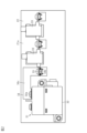
- FIG. 1 is an exploded perspective view of an electrical junction box according to an embodiment.
- FIG. 2 is a plan view of a lower case and electric circuit components according to an embodiment.
- FIG. 3 is a perspective view of a lower case and electric circuit components according to an embodiment.
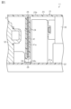
- FIG. 4 is a partial cross-sectional view of the electrical junction box according to one embodiment.
- FIG. 5 is a cross-sectional view taken along line 5-5 of FIG.
- the electrical connection box of the present disclosure comprises: [1] An electrical junction box comprising a case made of a resin material and electrical circuit components housed and held within the case, the electrical circuit components including a current sensor and a magnetic field generating component that generates a magnetic field, the electrical junction box comprising a metal plate interposed between the magnetic field generating component and the current sensor, and the case having a covering portion covering a main surface of the metal plate inside the case.
- the case has a coating portion that covers the main surface of the metal plate inside the case, the metal plate is prevented from coming into direct contact with other electrical circuit components. This prevents, for example, the bus bar connecting the magnetic field generating component and the current sensor from being electrically connected to the metal plate. It also prevents, for example, a flexible coated electric wire from being damaged by rubbing against the corners of the metal plate.
- the case may have an insertion opening through which the metal plate can be inserted between the coated parts from the outside, and a housing bottom that connects the coated parts at the tip end in the insertion direction of the metal plate.
- the case has an insertion opening through which a metal plate can be inserted between the coated parts from the outside, and a housing bottom that connects the coated parts at the tip end in the direction in which the metal plate is inserted, so the metal plate can be easily positioned by inserting it through the insertion opening.
- the electric circuit component may include a bus bar that connects the magnetic field generating component and the current sensor, and the bus bar may be arranged so that its main surface faces the bottom surface inside the case.
- the bus bar connecting the magnetic field generating component and the current sensor is positioned so that its main surface faces the bottom surface inside the case, so that a metal plate can be easily interposed between the magnetic field generating component and the current sensor. That is, for example, in a configuration in which the bus bar is positioned so that its main surface is perpendicular to the bottom surface of the case, the bus bar gets in the way, making it difficult to interpose a metal plate between the magnetic field generating component and the current sensor, but this can be avoided.
- the metal plate may have multiple different planar portions arranged to surround the current sensor or the magnetic field generating component.
- the metal plate has multiple different planar sections arranged to surround the current sensor or the magnetic field generating component, so the magnetic field generating component and the current sensor can be neatly separated compared to when the planar section is a single metal plate.
- the metal plate may have a bent portion connecting the plurality of different planar portions together.
- the metal plate has bent portions that connect the multiple different planar portions together, so that the number of parts can be reduced compared to, for example, a case in which the multiple different planar portions are each independent, separate members.
- the metal plate may be arranged so as to block both the surface of the current sensor facing the magnetic field generating component and the surface of the magnetic field generating component facing the current sensor.
- the metal plate is positioned so as to completely block the surface of the current sensor facing the magnetic field generating component and the surface of the magnetic field generating component facing the current sensor, so the current sensor can be more effectively prevented from being affected by the magnetic field compared to a configuration in which only a portion of the surface is not blocked. This makes it possible to more effectively prevent a decrease in the detection accuracy of the current sensor.
- the electrical junction box 11 includes a case 21, electrical circuit components 31, and a metal plate 41.
- the electrical junction box 11 of this embodiment is provided in, for example, a battery pack mounted on a vehicle such as an electric vehicle. That is, the electrical junction box 11 is housed in a battery pack case together with a plurality of battery cells.
- the case 21 has a lower case 22 and an upper case 23.
- the lower case 22 and the upper case 23 are each made of a resin material.
- the lower case 22 is formed in a rectangular flat plate shape.
- the upper case 23 is configured so as to be able to be assembled above the lower case 22.
- the upper case 23 has a square cylindrical side wall portion 23a corresponding to the periphery of the lower case 22, and an upper wall portion 23b closing the upper end of the side wall portion 23a.
- the electric circuit components 31 are disposed on the upper surface of the lower case 22 , which is the bottom surface 21 a within the case 21 , and are housed and held within the case 21 .
- the electric circuit components 31 include a contactor 32 as a magnetic field generating component that generates a magnetic field, a current sensor 33, and a bus bar 34. Note that in each figure of this embodiment, only one contactor 32, two current sensors 33, and one bus bar 34 are illustrated, and the other electric circuit components 31 are not illustrated. That is, the electric circuit components 31 provided in the electric junction box 11 may include, for example, multiple contactors 32 and multiple bus bars 34, or may include other electric circuit components 31 such as flexible coated wires and fuses.
- the current sensor 33 in this embodiment has a Hall element, but is not limited to this and may be a through-type current sensor.
- the contactor 32 and the two current sensors 33 are arranged side by side along one side, specifically along the long side, of the lower case 22.
- the contactor 32 is connected to the connection terminal 33a of one of the two current sensors 33 connected in series via a bus bar 34.
- the busbar 34 is disposed so that the main surface of the busbar 34 faces the bottom surface 21a inside the case 21. More specifically, the busbar 34 has a first connection end 34a, a second connection end 34b, and a connecting portion 34c that connects the first connection end 34a and the second connection end 34b.
- the main surface of the connecting portion 34c is disposed so that it faces the bottom surface 21a inside the case 21.
- the first connection end 34a is raised from the connecting portion 34c so that the main surface of the busbar 34 is perpendicular to the bottom surface 21a, and is connected to the contactor 32.
- the second connection end 34b is raised from the connecting portion 34c so that the main surface of the busbar 34 is perpendicular to the bottom surface 21a, and is connected to the connection terminal 33a of the current sensor 33.
- the metal plate 41 is interposed between the contactor 32 and the current sensor 33.
- the metal plate 41 is provided so as to separate the contactor 32 and the current sensor 33.
- the case 21 has a covering portion 24 that covers the main surface of the metal plate 41 inside the case 21.
- the covering portion 24 is provided on the upper case 23.
- the covering portion 24 is formed so as to cover the entire main surface of the metal plate 41.
- the metal plate 41 has a first planar portion 41a and a second planar portion 41b as two different planar portions arranged to surround the current sensor 33.
- the metal plate 41 also has a bent portion 41c connecting the first planar portion 41a and the second planar portion 41b.
- the metal plate 41 is made of a single folded part.
- the first planar portion 41a and the second planar portion 41b extend in directions perpendicular to each other from the bent portion 41c.
- the first planar portion 41a of the metal plate 41 is arranged parallel to the short side of the lower case 22, and the second planar portion 41b is arranged parallel to the long side of the lower case 22.
- the metal plate 41 is arranged so as to surround the current sensor 33 with the edge of the lower case 22.
- the metal plate 41 is positioned so as to block both the surface of the current sensor 33 facing the contactor 32 and the surface of the contactor 32 facing the current sensor 33.
- the first flat portion 41a which is a part of the metal plate 41, is arranged so as to pass above the connecting portion 34c of the busbar 34.
- the first flat portion 41a is arranged so as to cross the connecting portion 34c that extends along the long side of the lower case 22.
- the upper case 23 has an insertion opening 25 through which a metal plate 41 can be inserted between the covering portions 24 from the outside, and a housing bottom 26 that connects the covering portions 24 at the tip of the metal plate 41 in the insertion direction.
- the insertion opening 25 in this embodiment is provided in the upper wall portion 23b of the upper case 23 and opens upward.
- the metal plate 41 is fixed by being pressed into between the covering portions 24 from the insertion opening 25.
- a plurality of press-fitting protrusions are provided on the opposing surfaces of the covering portions 24, and the metal plate 41 is held by being clamped between these press-fitting protrusions.
- the electric circuit components 31 of the electric junction box 11 are electrically connected to the battery cells housed in the battery pack case together with the electric junction box 11.
- the electric circuit components 31 of the electric junction box 11 monitor the current values, temperatures, etc. of the battery cells, thereby achieving optimal input and output of the battery pack.
- the effects of the above embodiment will be described below.
- the metal plate 41 is provided between the contactor 32 and the current sensor 33, the current sensor 33 can be prevented from being affected by the magnetic field generated by the contactor 32. This can prevent a decrease in the detection accuracy of the current sensor 33. As a result, for example, it is no longer necessary to arrange the contactor 32 and the current sensor 33 far apart, making it easy to reduce the size of the electric connection box 11.
- the case 21 has a covering portion 24 that covers the main surface of the metal plate 41 inside the case 21, the metal plate 41 is prevented from directly contacting other electric circuit components 31. Therefore, for example, the bus bar 34 connecting the contactor 32 and the current sensor 33 is prevented from being electrically connected to the metal plate 41.
- the flexible covered electric wire (not shown) is damaged by rubbing against the corners of the metal plate 41.
- the case 21 has an insertion opening 25 through which the metal plate 41 can be inserted between the coated portions 24 from the outside, and a housing bottom 26 that connects the coated portions 24 at the tip end in the insertion direction of the metal plate 41. Therefore, the metal plate 41 can be easily positioned by inserting it from the insertion opening 25.
- the bus bar 34 connecting the contactor 32 and the current sensor 33 is arranged so that the main surface of the bus bar 34 faces the bottom surface 21a inside the case 21, so that the metal plate 41 can be easily interposed between the contactor 32 and the current sensor 33. That is, for example, in a configuration in which the bus bar 34 is arranged so that the main surface of the bus bar 34 is perpendicular to the bottom surface 21a, the bus bar gets in the way, making it difficult to interpose the metal plate 41 between the contactor 32 and the current sensor 33, but this can be avoided.
- the metal plate 41 has a first planar portion 41a and a second planar portion 41b that are two different planar portions arranged to surround the current sensor 33. Therefore, for example, the contactor 32 and the current sensor 33 can be neatly separated compared to when the planar portion is a single metal plate.
- the metal plate 41 has a bent portion 41c that connects the first planar portion 41a and the second planar portion 41b, so the number of parts can be reduced compared to, for example, a case in which the first planar portion 41a and the second planar portion 41b are each separate, independent members.
- the metal plate 41 is arranged so as to completely block the surface of the current sensor 33 facing the contactor 32 and the surface of the contactor 32 facing the current sensor 33. Therefore, compared to a configuration in which, for example, only a portion of the surface is not blocked, the current sensor 33 can be more effectively prevented from being affected by the magnetic field generated by the contactor 32. Therefore, the deterioration of the detection accuracy of the current sensor 33 can be more effectively prevented.
- the case 21 has the insertion opening 25 through which the metal plate 41 can be inserted between the covering portions 24 from the outside, and the housing bottom portion 26 that connects the covering portions 24 at the tip end in the insertion direction of the metal plate 41, but is not limited to this.
- the metal plate 41 may be provided so as to be covered by the covering portion of the upper case 23 by insert molding when the upper case 23 is molded.
- the insertion opening 25 is provided in the upper wall portion 23b of the upper case 23 and opens upward, but this is not limited thereto, and for example, it may be provided in the side wall portion 23a and open to the side. Also, the covering portion 24, the insertion opening 25, and the housing bottom portion 26 may be provided in the lower case 22, and the insertion opening 25 may open downward.
- the bus bar 34 connecting the contactor 32 and the current sensor 33 is arranged so that the main surface of the bus bar 34 faces the bottom surface 21a inside the case 21, but this is not limited to this, and the main surface of the bus bar 34 may be arranged so that it is perpendicular to the bottom surface 21a.
- the metal plate 41 has two different planar portions, the first planar portion 41a and the second planar portion 41b, arranged to surround the current sensor 33, but is not limited to this and may have, for example, three or more different planar portions. Also, for example, the planar portion may be a single metal plate.
- the metal plate 41 has a bent portion 41c that connects the first planar portion 41a and the second planar portion 41b, but this is not limited thereto.
- the first planar portion 41a and the second planar portion 41b may each be separate, independent members.
- the metal plate 41 is arranged to completely block the surface of the current sensor 33 facing the contactor 32 and the surface of the contactor 32 facing the current sensor 33, but this is not limited thereto, and the metal plate 41 may be arranged to block only a portion of the surface.
- the electric circuit component 31 includes the contactor 32 as a magnetic field generating component, but is not limited to this and may include other magnetic field generating components such as a core that generates a magnetic field.
- the metal plate 41 will be interposed between the other magnetic field generating components such as the core and the current sensor 33.
- the metal plate 41 is fixed by being pressed into the space between the insertion opening 25 and the covering portion 24, but this is not limited thereto, and the metal plate 41 may be configured to be prevented from coming out by a claw or the like while inserted between the insertion opening 25 and the covering portion 24.
- the electrical connection box 11 is provided in a battery pack mounted on a vehicle such as an electric vehicle, but is not limited to this and may be provided in other devices.
- the contactor 32 of the illustrated non-limiting embodiment is an example of an electromagnetic coil type magnetic noise source or a non-sensor magnetic noise source.
- the covering portion 24 and the housing bottom portion 26 may be referred to as a partition configured to divide the internal space of the case 21 into a magnetic noise source compartment (e.g., the space on the left in FIG. 5) for housing an electromagnetic coil type magnetic noise source, which may be the contactor 32, and a current sensor compartment (e.g., the space on the right in FIG. 5) for housing the current sensor 33.
- This partition may extend linearly from the top surface of the upper case 23 to the bottom surface of the lower case 22, as shown in FIG. 5, and may have, for example, a hollow double-wall structure.
- the metal plate 41 of the illustrated non-limiting embodiment is an example of a magnetic noise shield plate having an outermost edge, a plate thickness, a plate width, and a plate length, and may optionally have a bent corner or an alignment corner.
- the insertion opening 25, the covering portion 24, and the accommodation bottom portion 26 of the case 21 are an example of a slot-shaped holder.
- This slot-shaped holder may be configured to accommodate the entire metal plate 41 so that the outermost edge of the metal plate 41 does not protrude from the outline or outermost surface of the case 21 and the surface of the metal plate 41 is not exposed to the internal space of the case 21.
- This slot-shaped holder may have a slot width that matches or corresponds to the thickness of the metal plate 41, a slot depth that matches or corresponds to the width of the metal plate 41, and a slot length that matches or corresponds to the length of the metal plate 41.
- the slot-shaped holder may have a bent space that corresponds to the bent corner or the alignment corner of the metal plate 41.
- the insertion opening 25 on the outer surface of the case 21 is configured to allow insertion into the slot-like holder from outside the case 21 and may be referred to as a slot-like entrance.
- the insertion opening 25 of the case 21 may be configured to allow removal of the metal plate 41 from the slot-like holder to outside the case 21.
Landscapes
- Engineering & Computer Science (AREA)
- Microelectronics & Electronic Packaging (AREA)
- Architecture (AREA)
- Civil Engineering (AREA)
- Structural Engineering (AREA)
- Connection Or Junction Boxes (AREA)
- Shielding Devices Or Components To Electric Or Magnetic Fields (AREA)
- Battery Mounting, Suspending (AREA)
Abstract
電気接続箱(11)は、樹脂材よりなるケース(21)と、ケース(21)内に収容保持される電気回路部品(31)とを備え、電気回路部品(31)は、磁界を発生させることになるコンタクタ(32)と、電流センサ(33)とを含む。電気接続箱(11)は、コンタクタ(32)と電流センサ(33)との間に介在される金属板(41)を備える。ケース(21)は、ケース(21)の内部において金属板(41)の主面を覆う被覆部(24)を有する。
Description
本開示は、電気接続箱に関するものである。
従来、電気接続箱としては、例えば、車両の電池パックに設けられるものがある(例えば、特許文献1参照)。電池パックは、電池パックケースと電気接続箱と複数の電池セルとを備える。
電気接続箱は、樹脂材よりなるケースと、ケース内に収容保持される電気回路部品とを備える。電気回路部品は、リレーの一種であるコンタクタや、電流センサや、バスバー等を含む。電気回路部品は、電池セルの電流値や温度等を監視することにより、電池パックの最適な入出力を実現する。
ところで、上記したコンタクタは、内部にコイル部を有するため、動作する際に磁界を発生させてしまう。そして、電流センサは、磁界の影響を受けると検出精度が低下してしまう。このことは、特に電気接続箱の小型化を図る上で大きな問題となる。そこで、例えば、ケースの内部に、コンタクタと電流センサとの間を仕切る金属板を設けることが考えられる。しかしながら、ケースの内部に金属板を配置すると、金属板が他の電気部品と接触してしまう虞がある。具体的には、例えば、バスバーが金属板と電気的に接続されてしまう虞がある。また、例えば、柔軟な被覆電線が金属板の角等に擦れることによって損傷してしまう虞がある。
本開示の目的は、電気回路部品と金属板との接触を防止しながら、電流センサの検出精度の低下を抑制可能とした電気接続箱を提供することにある。
本開示の電気接続箱は、樹脂材よりなるケースと、前記ケース内に収容保持される電気回路部品とを備え、前記電気回路部品は、電流センサと、磁界を発生させることになる磁界発生部品とを含む、電気接続箱であって、前記磁界発生部品と前記電流センサとの間に介在される金属板を備え、前記ケースは、前記ケースの内部において前記金属板の主面を覆う被覆部を有する。
本開示の電気接続箱によれば、電気回路部品と金属板との接触を防止しながら、電流センサの検出精度の低下を抑制できる。
[本開示の実施形態の説明]
最初に本開示の実施態様を列記して説明する。
本開示の電気接続箱は、
[1]樹脂材よりなるケースと、前記ケース内に収容保持される電気回路部品とを備え、前記電気回路部品は、電流センサと、磁界を発生させることになる磁界発生部品とを含む、電気接続箱であって、前記磁界発生部品と前記電流センサとの間に介在される金属板を備え、前記ケースは、前記ケースの内部において前記金属板の主面を覆う被覆部を有する。
最初に本開示の実施態様を列記して説明する。
本開示の電気接続箱は、
[1]樹脂材よりなるケースと、前記ケース内に収容保持される電気回路部品とを備え、前記電気回路部品は、電流センサと、磁界を発生させることになる磁界発生部品とを含む、電気接続箱であって、前記磁界発生部品と前記電流センサとの間に介在される金属板を備え、前記ケースは、前記ケースの内部において前記金属板の主面を覆う被覆部を有する。
同構成によれば、磁界発生部品と電流センサとの間に介在される金属板を備えるため、磁界発生部品が発生する磁界の影響を電流センサが受けてしまうことを抑制できる。よって、電流センサの検出精度の低下を抑制できる。また、ケースは、ケースの内部において金属板の主面を覆う被覆部を有するため、金属板が他の電気回路部品と直接接触することが防止される。よって、例えば、磁界発生部品と電流センサとを接続するバスバーが金属板と電気的に接続されてしまうといったことが防止される。また、例えば、柔軟な被覆電線が金属板の角等に擦れることによって損傷してしまうといったことが防止される。
[2]上記[1]において、前記ケースは、外部から前記被覆部同士の間に前記金属板を挿入可能な挿入口と、前記金属板の挿入方向の先端部で前記被覆部同士を繋ぐ収容底部とを有していてもよい。
同構成によれば、ケースは、外部から被覆部同士の間に金属板を挿入可能な挿入口と、金属板の挿入方向の先端部で被覆部同士を繋ぐ収容底部とを有するため、金属板を挿入口から挿入することで金属板を容易に配置することができる。
[3]上記[1]または上記[2]において、前記電気回路部品は、前記磁界発生部品と前記電流センサとを接続するバスバーを含み、前記バスバーは、その主面が前記ケース内の底面と対向するように配置されていてもよい。
同構成によれば、磁界発生部品と電流センサとを接続するバスバーは、その主面がケース内の底面と対向するように配置されるため、金属板を磁界発生部品と電流センサとの間に容易に介在させることができる。すなわち、例えば、バスバーの主面がケースの底面と直交するようにバスバーが配置される構成では、バスバーが邪魔になることで、金属板を磁界発生部品と電流センサとの間に介在させることが困難になるが、これを回避できる。
[4]上記[1]から上記[3]のいずれか1つにおいて、前記金属板は、前記電流センサ、または前記磁界発生部品を囲うように配置された複数の異なる平面部を有していてもよい。
同構成によれば、金属板は、電流センサ、または磁界発生部品を囲うように配置された複数の異なる平面部を有するため、平面部が単一の金属板とした場合に比べて、磁界発生部品と電流センサとを整然と仕切ることができる。
[5]上記[4]において、前記金属板は、前記複数の異なる平面部同士を繋ぐ折り曲げ部を有していてもよい。
同構成によれば、金属板は、複数の異なる平面部同士を繋ぐ折り曲げ部を有するため、例えば、複数の異なる平面部がそれぞれ独立した別部材である場合に対して、部品点数を少なくすることができる。
同構成によれば、金属板は、複数の異なる平面部同士を繋ぐ折り曲げ部を有するため、例えば、複数の異なる平面部がそれぞれ独立した別部材である場合に対して、部品点数を少なくすることができる。
[6]上記[1]から上記[5]のいずれか1つにおいて、前記金属板は、前記電流センサにおける前記磁界発生部品との対向面と、前記磁界発生部品における前記電流センサとの対向面との全て遮るように配置されていてもよい。
同構成によれば、金属板は、電流センサにおける磁界発生部品との対向面と、磁界発生部品における電流センサとの対向面との全て遮るように配置されているため、一部が遮られていない構成に比べて、磁界の影響を電流センサが受けることをより抑制できる。よって、電流センサの検出精度の低下をより抑制できる。
[本開示の実施形態の詳細]
本開示の電気接続箱の具体例を、以下に図面を参照しつつ説明する。各図面では、説明の便宜上、構成の一部を誇張又は簡略化して示す場合がある。また、各部分の寸法比率については各図面で異なる場合がある。本明細書における「平行」や「直交」や「真円」は、厳密に平行や直交や真円の場合のみでなく、本実施形態における作用効果を奏する範囲内で概ね平行や直交や真円の場合も含まれる。なお、本発明はこれらの例示に限定されるものではなく、特許請求の範囲によって示され、特許請求の範囲と均等の意味及び範囲内でのすべての変更が含まれることが意図される。
本開示の電気接続箱の具体例を、以下に図面を参照しつつ説明する。各図面では、説明の便宜上、構成の一部を誇張又は簡略化して示す場合がある。また、各部分の寸法比率については各図面で異なる場合がある。本明細書における「平行」や「直交」や「真円」は、厳密に平行や直交や真円の場合のみでなく、本実施形態における作用効果を奏する範囲内で概ね平行や直交や真円の場合も含まれる。なお、本発明はこれらの例示に限定されるものではなく、特許請求の範囲によって示され、特許請求の範囲と均等の意味及び範囲内でのすべての変更が含まれることが意図される。
(電気接続箱11の構成)
図1に示すように、電気接続箱11は、ケース21と、電気回路部品31と、金属板41とを備える。本実施形態の電気接続箱11は、例えば、電気自動車等の車両に搭載される電池パックに設けられるものである。すなわち、電気接続箱11は、複数の電池セルと共に電池パックケース内に収容されるものである。
図1に示すように、電気接続箱11は、ケース21と、電気回路部品31と、金属板41とを備える。本実施形態の電気接続箱11は、例えば、電気自動車等の車両に搭載される電池パックに設けられるものである。すなわち、電気接続箱11は、複数の電池セルと共に電池パックケース内に収容されるものである。
(ケース21の構成)
ケース21は、下ケース22と、上ケース23とを有する。下ケース22及び上ケース23の各々は樹脂材よりなる。下ケース22は、長方形の平板状に形成されている。上ケース23は、下ケース22の上方に組み付け可能に構成されている。上ケース23は、下ケース22の周縁に対応した四角筒状の側壁部23aと、側壁部23aの上端を閉塞する上壁部23bとを有する。
ケース21は、下ケース22と、上ケース23とを有する。下ケース22及び上ケース23の各々は樹脂材よりなる。下ケース22は、長方形の平板状に形成されている。上ケース23は、下ケース22の上方に組み付け可能に構成されている。上ケース23は、下ケース22の周縁に対応した四角筒状の側壁部23aと、側壁部23aの上端を閉塞する上壁部23bとを有する。
(電気回路部品31の構成)
電気回路部品31は、ケース21内の底面21aである下ケース22の上面に配置されつつ、ケース21内に収容保持される。
電気回路部品31は、ケース21内の底面21aである下ケース22の上面に配置されつつ、ケース21内に収容保持される。
図2及び図3に示すように、電気回路部品31は、磁界を発生させることになる磁界発生部品としてのコンタクタ32と、電流センサ33と、バスバー34とを含む。なお、本実施形態における各図では、1つのコンタクタ32、2つの電流センサ33、及び、1つのバスバー34のみを図示しており、他の電気回路部品31の図示を省略している。すなわち、電気接続箱11が備える電気回路部品31は、例えば、複数のコンタクタ32や複数のバスバー34を含んでいてもよいし、柔軟な被覆電線やヒューズ等の他の電気回路部品31を含んでいてもよい。また、本実施形態の電流センサ33は、ホール素子を有するものを採用しているが、これに限定されず、貫通型の電流センサとしてもよい。
本実施形態では、コンタクタ32と2つの電流センサ33とは、下ケース22の1つの辺であって、詳しくは、長辺に沿って並設されている。コンタクタ32は、直列に接続された2つの電流センサ33における一方の電流センサ33の接続端子33aにバスバー34を介して接続されている。
図3に示すように、バスバー34は、バスバー34の主面がケース21内の底面21aと対向するように配置されている。詳しくは、バスバー34は、第1接続端部34aと、第2接続端部34bと、第1接続端部34aと第2接続端部34bとを繋ぐ連結部34cとを有する。そして、連結部34cの主面は、ケース21内の底面21aと対向するように配置されている。そして、第1接続端部34aは、バスバー34の主面が底面21aと直交するように連結部34cから立ち上げられて、コンタクタ32に接続されている。また、第2接続端部34bは、バスバー34の主面が底面21aと直交するように連結部34cから立ち上げられて、電流センサ33の接続端子33aに接続されている。
(金属板41の構成)
図4及び図5に示すように、金属板41は、コンタクタ32と電流センサ33との間に介在されている。言い換えると、金属板41は、コンタクタ32と電流センサ33との間を仕切るように設けられている。
図4及び図5に示すように、金属板41は、コンタクタ32と電流センサ33との間に介在されている。言い換えると、金属板41は、コンタクタ32と電流センサ33との間を仕切るように設けられている。
そして、ケース21は、ケース21の内部において金属板41の主面を覆う被覆部24を有する。本実施形態の被覆部24は、上ケース23に設けられている。被覆部24は、金属板41の主面の全てを覆うように形成されている。
詳述すると、図4に示すように、まず金属板41は、電流センサ33を囲うように配置された2つの異なる平面部としての第1平面部41a及び第2平面部41bを有する。また、金属板41は、第1平面部41aと第2平面部41bとを繋ぐ折り曲げ部41cを有する。すなわち、金属板41は、折り曲げられた単一の部品よりなる。第1平面部41aと第2平面部41bとは、折り曲げ部41cから互いに直交する方向に延びている。そして、金属板41は、第1平面部41aが下ケース22の短辺と平行に配置されるとともに、第2平面部41bが下ケース22の長辺と平行に配置されている。金属板41は、下ケース22の縁部とで電流センサ33を囲うように配置されている。金属板41は、電流センサ33におけるコンタクタ32との対向面と、コンタクタ32における電流センサ33との対向面との全て遮るように配置されている。
また、図4及び図5に示すように、金属板41の一部であって、第1平面部41aは、バスバー34における連結部34cの上方を通るように配置されている。第1平面部41aは、上方から見て、下ケース22の長辺に沿って延びる連結部34cを横切るように配置されている。
また、図5に示すように、上ケース23は、外部から被覆部24同士の間に金属板41を挿入可能な挿入口25と、金属板41の挿入方向の先端部で被覆部24同士を繋ぐ収容底部26とを有する。本実施形態の挿入口25は、上ケース23の上壁部23bに設けられ、上方に開口している。なお、本実施形態では、金属板41は、挿入口25から被覆部24の間に圧入されることにより固定されている。例えば、被覆部24同士の対向面には、図示しない複数の圧入用凸部が設けられており、それら圧入用凸部に挟持されることで金属板41は保持されている。
次に、上記のように構成された電気接続箱11の作用について説明する。
電気接続箱11の電気回路部品31は、電気接続箱11と共に電池パックケース内に収容される電池セルと電気的に接続される。そして、電気接続箱11の電気回路部品31が電池セルの電流値や温度等を監視することにより、電池パックの最適な入出力が実現される。
電気接続箱11の電気回路部品31は、電気接続箱11と共に電池パックケース内に収容される電池セルと電気的に接続される。そして、電気接続箱11の電気回路部品31が電池セルの電流値や温度等を監視することにより、電池パックの最適な入出力が実現される。
次に、上記実施形態の効果を以下に記載する。
(1)コンタクタ32と電流センサ33との間に介在される金属板41を備えるため、コンタクタ32が発生する磁界の影響を電流センサ33が受けてしまうことを抑制できる。よって、電流センサ33の検出精度の低下を抑制できる。これにより、例えば、コンタクタ32と電流センサ33とを大きく離して配置する必要が無くなり、電気接続箱11の小型化が容易となる。また、ケース21は、ケース21の内部において金属板41の主面を覆う被覆部24を有するため、金属板41が他の電気回路部品31と直接接触することが防止される。よって、例えば、コンタクタ32と電流センサ33とを接続するバスバー34が金属板41と電気的に接続されてしまうといったことが防止される。また、例えば、車両の走行時に電気接続箱11が振動した場合でも、柔軟な被覆電線(図示略)が金属板41の角等に擦れることによって損傷してしまうといったことが防止される。
(1)コンタクタ32と電流センサ33との間に介在される金属板41を備えるため、コンタクタ32が発生する磁界の影響を電流センサ33が受けてしまうことを抑制できる。よって、電流センサ33の検出精度の低下を抑制できる。これにより、例えば、コンタクタ32と電流センサ33とを大きく離して配置する必要が無くなり、電気接続箱11の小型化が容易となる。また、ケース21は、ケース21の内部において金属板41の主面を覆う被覆部24を有するため、金属板41が他の電気回路部品31と直接接触することが防止される。よって、例えば、コンタクタ32と電流センサ33とを接続するバスバー34が金属板41と電気的に接続されてしまうといったことが防止される。また、例えば、車両の走行時に電気接続箱11が振動した場合でも、柔軟な被覆電線(図示略)が金属板41の角等に擦れることによって損傷してしまうといったことが防止される。
(2)ケース21は、外部から被覆部24同士の間に金属板41を挿入可能な挿入口25と、金属板41の挿入方向の先端部で被覆部24同士を繋ぐ収容底部26とを有する。よって、金属板41を挿入口25から挿入することで金属板41を容易に配置することができる。
(3)コンタクタ32と電流センサ33とを接続するバスバー34は、バスバー34の主面がケース21内の底面21aと対向するように配置されるため、金属板41をコンタクタ32と電流センサ33との間に容易に介在させることができる。すなわち、例えば、バスバー34の主面が底面21aと直交するようにバスバーが配置される構成では、バスバーが邪魔になることで、金属板41をコンタクタ32と電流センサ33との間に介在させることが困難になるが、これを回避できる。
(4)金属板41は、電流センサ33を囲うように配置された2つの異なる平面部としての第1平面部41a及び第2平面部41bを有する。よって、例えば、平面部が単一の金属板とした場合に比べて、コンタクタ32と電流センサ33とを整然と仕切ることができる。
(5)金属板41は、第1平面部41aと第2平面部41bとを繋ぐ折り曲げ部41cを有するため、例えば、第1平面部41aと第2平面部41bとがそれぞれ独立した別部材である場合に対して、部品点数を少なくすることができる。
(6)金属板41は、電流センサ33におけるコンタクタ32との対向面と、コンタクタ32における電流センサ33との対向面との全て遮るように配置されている。よって、例えば、一部が遮られていない構成に比べて、コンタクタ32が発生する磁界の影響を電流センサ33が受けることをより抑制できる。よって、電流センサ33の検出精度の低下をより抑制できる。
本実施形態は、以下のように変更して実施することができる。本実施形態及び以下の変更例は、技術的に矛盾しない範囲で互いに組み合わせて実施することができる。
・上記実施形態では、ケース21は、外部から被覆部24同士の間に金属板41を挿入可能な挿入口25と、金属板41の挿入方向の先端部で被覆部24同士を繋ぐ収容底部26とを有するとしたが、これに限定されない。例えば、金属板41は、上ケース23の成形時にインサート成形することで上ケース23の被覆部に覆われるように設けてもよい。
・上記実施形態では、ケース21は、外部から被覆部24同士の間に金属板41を挿入可能な挿入口25と、金属板41の挿入方向の先端部で被覆部24同士を繋ぐ収容底部26とを有するとしたが、これに限定されない。例えば、金属板41は、上ケース23の成形時にインサート成形することで上ケース23の被覆部に覆われるように設けてもよい。
・上記実施形態では、挿入口25は、上ケース23の上壁部23bに設けられ、上方に開口しているとしたが、これに限定されず、例えば、側壁部23aに設けられ、側方に開口していてもよい。また、被覆部24、挿入口25及び収容底部26は、下ケース22に設けられ、挿入口25は下方に開口していてもよい。
・上記実施形態では、コンタクタ32と電流センサ33とを接続するバスバー34は、バスバー34の主面がケース21内の底面21aと対向するように配置されるとしたが、これに限定されず、バスバー34の主面が底面21aと直交するように配置されていてもよい。
・上記実施形態では、金属板41は、電流センサ33を囲うように配置された2つの異なる平面部としての第1平面部41a及び第2平面部41bを有するとしたが、これに限定されず、例えば、3つ以上の異なる平面部を有していてもよい。また、例えば、平面部が単一の金属板としてもよい。
・上記実施形態では、金属板41は、第1平面部41aと第2平面部41bとを繋ぐ折り曲げ部41cを有するとしたが、これに限定されず、例えば、第1平面部41aと第2平面部41bとがそれぞれ独立した別部材である構成としてもよい。
・上記実施形態では、金属板41は、電流センサ33におけるコンタクタ32との対向面と、コンタクタ32における電流センサ33との対向面との全て遮るように配置されているとしたが、これに限定されず、一部のみを遮る構成としてもよい。
・上記実施形態では、電気回路部品31は、磁界発生部品としてのコンタクタ32を含むとしたが、これに限定されず、磁界を発生させることになるコア等の他の磁界発生部品を含む構成としてもよい。なお、もちろん、この場合、金属板41は、コア等の他の磁界発生部品と電流センサ33との間に介在されることになる。
・上記実施形態では、金属板41は、挿入口25から被覆部24の間に圧入されることにより固定されているとしたが、これに限定されず、挿入口25から被覆部24の間に挿入された状態で、爪等によって抜け止めされる構成としてもよい。
・上記実施形態では、電気接続箱11は、電気自動車等の車両に搭載される電池パックに設けられるものであるとしたが、これに限定されず、他の装置に設けられるものとしてもよい。
・図示した非限定的実施形態のコンタクタ32は、電磁コイル式磁気ノイズ源または非センサ磁気ノイズ源の一例である。図4、5に示したように、被覆部24および収容底部26は、ケース21の内部空間を、コンタクタ32であり得る電磁コイル式磁気ノイズ源を収容するための磁気ノイズ源コンパートメント(例えば図5において左側の空間)と、電流センサ33を収容するための電流センサコンパートメント(例えば図5において右側の空間)とに仕切るように構成されたパーティションとして参照することがある。このパーティションは、図5に示すように、上ケース23の上面から下ケース22の下面に向かって直線的に延在してよく、例えば中空の二重壁構造を有してよい。
・図示した非限定的実施形態の金属板41は、最外縁と板厚と板幅と板長とを有する磁気ノイズシールド板の一例であり、任意で屈曲角部または位置合わせ角部を有し得る。図1、4、5に示したように、ケース21の挿入口25と被覆部24と収容底部26とは、スロット状ホルダの一例である。このスロット状ホルダは、金属板41の最外縁がケース21の輪郭または最外面から突出しないようにかつ金属板41の表面がケース21の内部空間に曝されないように金属板41の全体を収容するように構成されてよい。このスロット状ホルダは、金属板41の板厚に一致または対応するスロット幅と、金属板41の板幅に一致または対応するスロット深さと、金属板41の板長に一致または対応するスロット長さとを有してよい。金属板41が屈曲角部または位置合わせ角部を有する場合、このスロット状ホルダは、金属板41の屈曲角部または位置合わせ角部に対応する屈曲空間を有し得る。図5に示した例では、ケース21の外面の挿入口25は、ケース21の外部からこのスロット状ホルダへの挿入を可能にするように構成されており、スロット状エントランスとして参照することがある。任意選択で、ケース21の挿入口25は、このスロット状ホルダからケース21の外部への金属板41の取り出しを可能にするように構成されてもよい。
11 電気接続箱
21 ケース
21a 底面
22 下ケース
23 上ケース
23a 側壁部
23b 上壁部
24 被覆部
25 挿入口
26 収容底部
31 電気回路部品
32 コンタクタ(磁界発生部品)
33 電流センサ
33a 接続端子
34 バスバー
34a 第1接続端部
34b 第2接続端部
34c 連結部
41 金属板
41a 第1平面部(平面部)
41b 第2平面部(平面部)
41c 折り曲げ部
21 ケース
21a 底面
22 下ケース
23 上ケース
23a 側壁部
23b 上壁部
24 被覆部
25 挿入口
26 収容底部
31 電気回路部品
32 コンタクタ(磁界発生部品)
33 電流センサ
33a 接続端子
34 バスバー
34a 第1接続端部
34b 第2接続端部
34c 連結部
41 金属板
41a 第1平面部(平面部)
41b 第2平面部(平面部)
41c 折り曲げ部
Claims (6)
- 樹脂材よりなるケースと、前記ケース内に収容保持される電気回路部品とを備え、前記電気回路部品は、電流センサと、磁界を発生させることになる磁界発生部品とを含む、電気接続箱であって、
前記磁界発生部品と前記電流センサとの間に介在される金属板を備え、
前記ケースは、前記ケースの内部において前記金属板の主面を覆う被覆部を有する、
電気接続箱。 - 前記ケースは、外部から前記被覆部同士の間に前記金属板を挿入可能な挿入口と、前記金属板の挿入方向の先端部で前記被覆部同士を繋ぐ収容底部とを有する、
請求項1に記載の電気接続箱。 - 前記電気回路部品は、前記磁界発生部品と前記電流センサとを接続するバスバーを含み、
前記バスバーは、前記バスバーの主面が前記ケース内の底面と対向するように配置されている、
請求項1に記載の電気接続箱。 - 前記金属板は、前記電流センサ、または前記磁界発生部品を囲うように配置された複数の異なる平面部を有する、
請求項1に記載の電気接続箱。 - 前記金属板は、前記複数の異なる平面部同士を繋ぐ折り曲げ部を有する、
請求項4に記載の電気接続箱。 - 前記金属板は、前記電流センサにおける前記磁界発生部品との対向面と、前記磁界発生部品における前記電流センサとの対向面との全て遮るように配置されている、
請求項1に記載の電気接続箱。
Priority Applications (1)
| Application Number | Priority Date | Filing Date | Title |
|---|---|---|---|
| CN202480037174.7A CN121336333A (zh) | 2023-06-15 | 2024-06-12 | 电气连接箱 |
Applications Claiming Priority (2)
| Application Number | Priority Date | Filing Date | Title |
|---|---|---|---|
| JP2023-098666 | 2023-06-15 | ||
| JP2023098666A JP2024179658A (ja) | 2023-06-15 | 2023-06-15 | 電気接続箱 |
Publications (1)
| Publication Number | Publication Date |
|---|---|
| WO2024257811A1 true WO2024257811A1 (ja) | 2024-12-19 |
Family
ID=93852240
Family Applications (1)
| Application Number | Title | Priority Date | Filing Date |
|---|---|---|---|
| PCT/JP2024/021376 Ceased WO2024257811A1 (ja) | 2023-06-15 | 2024-06-12 | 電気接続箱 |
Country Status (3)
| Country | Link |
|---|---|
| JP (1) | JP2024179658A (ja) |
| CN (1) | CN121336333A (ja) |
| WO (1) | WO2024257811A1 (ja) |
Citations (3)
| Publication number | Priority date | Publication date | Assignee | Title |
|---|---|---|---|---|
| JP2013250160A (ja) * | 2012-05-31 | 2013-12-12 | Yazaki Corp | 電流センサ |
| WO2017141784A1 (ja) * | 2016-02-18 | 2017-08-24 | 株式会社オートネットワーク技術研究所 | 回路構成体および電気接続箱 |
| JP2021145486A (ja) * | 2020-03-12 | 2021-09-24 | 株式会社デンソー | 電力変換器 |
-
2023
- 2023-06-15 JP JP2023098666A patent/JP2024179658A/ja active Pending
-
2024
- 2024-06-12 WO PCT/JP2024/021376 patent/WO2024257811A1/ja not_active Ceased
- 2024-06-12 CN CN202480037174.7A patent/CN121336333A/zh active Pending
Patent Citations (3)
| Publication number | Priority date | Publication date | Assignee | Title |
|---|---|---|---|---|
| JP2013250160A (ja) * | 2012-05-31 | 2013-12-12 | Yazaki Corp | 電流センサ |
| WO2017141784A1 (ja) * | 2016-02-18 | 2017-08-24 | 株式会社オートネットワーク技術研究所 | 回路構成体および電気接続箱 |
| JP2021145486A (ja) * | 2020-03-12 | 2021-09-24 | 株式会社デンソー | 電力変換器 |
Also Published As
| Publication number | Publication date |
|---|---|
| JP2024179658A (ja) | 2024-12-26 |
| CN121336333A (zh) | 2026-01-13 |
Similar Documents
| Publication | Publication Date | Title |
|---|---|---|
| JP5779010B2 (ja) | バスバモジュール構造体 | |
| JP6085140B2 (ja) | バスバモジュールの電線配索構造 | |
| JP6441112B2 (ja) | 電子部品ユニット、及び、ワイヤハーネス | |
| WO2014014000A1 (ja) | バスバモジュール | |
| JP6574796B2 (ja) | バスバー保持構造 | |
| JP2014058910A (ja) | 車載用電動圧縮機 | |
| JP6434471B2 (ja) | 電子部品ユニット、電気接続箱、及び、ワイヤハーネス | |
| CN109564812B (zh) | 线圈组装体、电路结构体及电气接线箱 | |
| JP6044495B2 (ja) | 配線モジュール | |
| CN111834566B (zh) | 蓄电池封装体 | |
| JP7243550B2 (ja) | 電気接続箱 | |
| JP7444637B2 (ja) | バスバーモジュール | |
| JP7207238B2 (ja) | 電池配線モジュール | |
| JP2024179658A (ja) | 電気接続箱 | |
| JP7234847B2 (ja) | 電子モジュール | |
| EP3851333B1 (en) | Electrical connection box | |
| JP2013217866A (ja) | 電気接続箱及び電流センサ | |
| WO2014192943A1 (ja) | バスバモジュール及び電源装置 | |
| JP7812618B2 (ja) | 電気接続箱 | |
| JP6969907B2 (ja) | 電気接続箱、及び、ワイヤハーネス | |
| JP7674325B2 (ja) | 電子部品ユニットおよびワイヤハーネス | |
| JP2014106018A (ja) | 電流センサ及び電池モジュール | |
| JP7154975B2 (ja) | 電気接続箱 | |
| JP2021013268A (ja) | 電気接続箱 | |
| JP7283369B2 (ja) | 電気接続箱 |
Legal Events
| Date | Code | Title | Description |
|---|---|---|---|
| 121 | Ep: the epo has been informed by wipo that ep was designated in this application |
Ref document number: 24823426 Country of ref document: EP Kind code of ref document: A1 |
|
| NENP | Non-entry into the national phase |
Ref country code: DE |
|
| 122 | Ep: pct application non-entry in european phase |
Ref document number: 24823426 Country of ref document: EP Kind code of ref document: A1 |