WO2024253271A1 - 고에너지 밀도를 갖는 리튬 이차전지 - Google Patents
고에너지 밀도를 갖는 리튬 이차전지 Download PDFInfo
- Publication number
- WO2024253271A1 WO2024253271A1 PCT/KR2023/018112 KR2023018112W WO2024253271A1 WO 2024253271 A1 WO2024253271 A1 WO 2024253271A1 KR 2023018112 W KR2023018112 W KR 2023018112W WO 2024253271 A1 WO2024253271 A1 WO 2024253271A1
- Authority
- WO
- WIPO (PCT)
- Prior art keywords
- sulfur
- lithium
- battery
- sulfur battery
- positive electrode
- Prior art date
- Legal status (The legal status is an assumption and is not a legal conclusion. Google has not performed a legal analysis and makes no representation as to the accuracy of the status listed.)
- Ceased
Links
Images


Classifications
-
- H—ELECTRICITY
- H01—ELECTRIC ELEMENTS
- H01M—PROCESSES OR MEANS, e.g. BATTERIES, FOR THE DIRECT CONVERSION OF CHEMICAL ENERGY INTO ELECTRICAL ENERGY
- H01M10/00—Secondary cells; Manufacture thereof
- H01M10/05—Accumulators with non-aqueous electrolyte
- H01M10/052—Li-accumulators
-
- H—ELECTRICITY
- H01—ELECTRIC ELEMENTS
- H01M—PROCESSES OR MEANS, e.g. BATTERIES, FOR THE DIRECT CONVERSION OF CHEMICAL ENERGY INTO ELECTRICAL ENERGY
- H01M4/00—Electrodes
- H01M4/02—Electrodes composed of, or comprising, active material
- H01M4/36—Selection of substances as active materials, active masses, active liquids
- H01M4/58—Selection of substances as active materials, active masses, active liquids of inorganic compounds other than oxides or hydroxides, e.g. sulfides, selenides, tellurides, halogenides or LiCoFy; of polyanionic structures, e.g. phosphates, silicates or borates
- H01M4/583—Carbonaceous material, e.g. graphite-intercalation compounds or CFx
-
- H—ELECTRICITY
- H01—ELECTRIC ELEMENTS
- H01M—PROCESSES OR MEANS, e.g. BATTERIES, FOR THE DIRECT CONVERSION OF CHEMICAL ENERGY INTO ELECTRICAL ENERGY
- H01M10/00—Secondary cells; Manufacture thereof
- H01M10/04—Construction or manufacture in general
- H01M10/0422—Cells or battery with cylindrical casing
-
- H—ELECTRICITY
- H01—ELECTRIC ELEMENTS
- H01M—PROCESSES OR MEANS, e.g. BATTERIES, FOR THE DIRECT CONVERSION OF CHEMICAL ENERGY INTO ELECTRICAL ENERGY
- H01M10/00—Secondary cells; Manufacture thereof
- H01M10/42—Methods or arrangements for servicing or maintenance of secondary cells or secondary half-cells
- H01M10/4235—Safety or regulating additives or arrangements in electrodes, separators or electrolyte
-
- H—ELECTRICITY
- H01—ELECTRIC ELEMENTS
- H01M—PROCESSES OR MEANS, e.g. BATTERIES, FOR THE DIRECT CONVERSION OF CHEMICAL ENERGY INTO ELECTRICAL ENERGY
- H01M4/00—Electrodes
- H01M4/02—Electrodes composed of, or comprising, active material
- H01M4/13—Electrodes for accumulators with non-aqueous electrolyte, e.g. for lithium-accumulators; Processes of manufacture thereof
-
- H—ELECTRICITY
- H01—ELECTRIC ELEMENTS
- H01M—PROCESSES OR MEANS, e.g. BATTERIES, FOR THE DIRECT CONVERSION OF CHEMICAL ENERGY INTO ELECTRICAL ENERGY
- H01M4/00—Electrodes
- H01M4/02—Electrodes composed of, or comprising, active material
- H01M4/36—Selection of substances as active materials, active masses, active liquids
- H01M4/362—Composites
-
- H—ELECTRICITY
- H01—ELECTRIC ELEMENTS
- H01M—PROCESSES OR MEANS, e.g. BATTERIES, FOR THE DIRECT CONVERSION OF CHEMICAL ENERGY INTO ELECTRICAL ENERGY
- H01M4/00—Electrodes
- H01M4/02—Electrodes composed of, or comprising, active material
- H01M4/36—Selection of substances as active materials, active masses, active liquids
- H01M4/38—Selection of substances as active materials, active masses, active liquids of elements or alloys
-
- H—ELECTRICITY
- H01—ELECTRIC ELEMENTS
- H01M—PROCESSES OR MEANS, e.g. BATTERIES, FOR THE DIRECT CONVERSION OF CHEMICAL ENERGY INTO ELECTRICAL ENERGY
- H01M4/00—Electrodes
- H01M4/02—Electrodes composed of, or comprising, active material
- H01M4/36—Selection of substances as active materials, active masses, active liquids
- H01M4/58—Selection of substances as active materials, active masses, active liquids of inorganic compounds other than oxides or hydroxides, e.g. sulfides, selenides, tellurides, halogenides or LiCoFy; of polyanionic structures, e.g. phosphates, silicates or borates
- H01M4/581—Chalcogenides or intercalation compounds thereof
- H01M4/5815—Sulfides
-
- H—ELECTRICITY
- H01—ELECTRIC ELEMENTS
- H01M—PROCESSES OR MEANS, e.g. BATTERIES, FOR THE DIRECT CONVERSION OF CHEMICAL ENERGY INTO ELECTRICAL ENERGY
- H01M4/00—Electrodes
- H01M4/02—Electrodes composed of, or comprising, active material
- H01M4/36—Selection of substances as active materials, active masses, active liquids
- H01M4/58—Selection of substances as active materials, active masses, active liquids of inorganic compounds other than oxides or hydroxides, e.g. sulfides, selenides, tellurides, halogenides or LiCoFy; of polyanionic structures, e.g. phosphates, silicates or borates
- H01M4/583—Carbonaceous material, e.g. graphite-intercalation compounds or CFx
- H01M4/587—Carbonaceous material, e.g. graphite-intercalation compounds or CFx for inserting or intercalating light metals
-
- H—ELECTRICITY
- H01—ELECTRIC ELEMENTS
- H01M—PROCESSES OR MEANS, e.g. BATTERIES, FOR THE DIRECT CONVERSION OF CHEMICAL ENERGY INTO ELECTRICAL ENERGY
- H01M50/00—Constructional details or processes of manufacture of the non-active parts of electrochemical cells other than fuel cells, e.g. hybrid cells
- H01M50/10—Primary casings; Jackets or wrappings
- H01M50/102—Primary casings; Jackets or wrappings characterised by their shape or physical structure
- H01M50/105—Pouches or flexible bags
-
- H—ELECTRICITY
- H01—ELECTRIC ELEMENTS
- H01M—PROCESSES OR MEANS, e.g. BATTERIES, FOR THE DIRECT CONVERSION OF CHEMICAL ENERGY INTO ELECTRICAL ENERGY
- H01M50/00—Constructional details or processes of manufacture of the non-active parts of electrochemical cells other than fuel cells, e.g. hybrid cells
- H01M50/10—Primary casings; Jackets or wrappings
- H01M50/102—Primary casings; Jackets or wrappings characterised by their shape or physical structure
- H01M50/107—Primary casings; Jackets or wrappings characterised by their shape or physical structure having curved cross-section, e.g. round or elliptic
-
- H—ELECTRICITY
- H01—ELECTRIC ELEMENTS
- H01M—PROCESSES OR MEANS, e.g. BATTERIES, FOR THE DIRECT CONVERSION OF CHEMICAL ENERGY INTO ELECTRICAL ENERGY
- H01M4/00—Electrodes
- H01M4/02—Electrodes composed of, or comprising, active material
- H01M2004/021—Physical characteristics, e.g. porosity, surface area
-
- H—ELECTRICITY
- H01—ELECTRIC ELEMENTS
- H01M—PROCESSES OR MEANS, e.g. BATTERIES, FOR THE DIRECT CONVERSION OF CHEMICAL ENERGY INTO ELECTRICAL ENERGY
- H01M4/00—Electrodes
- H01M4/02—Electrodes composed of, or comprising, active material
- H01M2004/026—Electrodes composed of, or comprising, active material characterised by the polarity
- H01M2004/027—Negative electrodes
-
- H—ELECTRICITY
- H01—ELECTRIC ELEMENTS
- H01M—PROCESSES OR MEANS, e.g. BATTERIES, FOR THE DIRECT CONVERSION OF CHEMICAL ENERGY INTO ELECTRICAL ENERGY
- H01M4/00—Electrodes
- H01M4/02—Electrodes composed of, or comprising, active material
- H01M2004/026—Electrodes composed of, or comprising, active material characterised by the polarity
- H01M2004/028—Positive electrodes
-
- H—ELECTRICITY
- H01—ELECTRIC ELEMENTS
- H01M—PROCESSES OR MEANS, e.g. BATTERIES, FOR THE DIRECT CONVERSION OF CHEMICAL ENERGY INTO ELECTRICAL ENERGY
- H01M10/00—Secondary cells; Manufacture thereof
- H01M10/42—Methods or arrangements for servicing or maintenance of secondary cells or secondary half-cells
- H01M2010/4292—Aspects relating to capacity ratio of electrodes/electrolyte or anode/cathode
-
- Y—GENERAL TAGGING OF NEW TECHNOLOGICAL DEVELOPMENTS; GENERAL TAGGING OF CROSS-SECTIONAL TECHNOLOGIES SPANNING OVER SEVERAL SECTIONS OF THE IPC; TECHNICAL SUBJECTS COVERED BY FORMER USPC CROSS-REFERENCE ART COLLECTIONS [XRACs] AND DIGESTS
- Y02—TECHNOLOGIES OR APPLICATIONS FOR MITIGATION OR ADAPTATION AGAINST CLIMATE CHANGE
- Y02E—REDUCTION OF GREENHOUSE GAS [GHG] EMISSIONS, RELATED TO ENERGY GENERATION, TRANSMISSION OR DISTRIBUTION
- Y02E60/00—Enabling technologies; Technologies with a potential or indirect contribution to GHG emissions mitigation
- Y02E60/10—Energy storage using batteries
Definitions
- the present invention relates to a lithium secondary battery, and particularly to a lithium sulfur battery having high energy density.
- lithium secondary batteries As the scope of application of lithium secondary batteries expands from portable electronic devices to electric vehicles (EVs) and electric storage systems (ESS), the demand for high-capacity, high-energy density, and long-life lithium secondary batteries is increasing.
- EVs electric vehicles
- ESS electric storage systems
- lithium-sulfur batteries are battery systems that use sulfur-based materials containing sulfur-sulfur bonds as positive electrode active materials, and lithium metal, carbon-based materials in which lithium ions can be inserted/deinserted, or silicon or tin that form alloys with lithium as negative electrode active materials.
- Sulfur the main material of the cathode active material in lithium-sulfur batteries, has the advantages of being a low atomic weight, abundant in resources, easy to supply, inexpensive, non-toxic, and environmentally friendly material.
- the lithium-sulfur battery has a theoretical specific capacity of 1,675 mAh/g from the conversion reaction of lithium ions and sulfur at the cathode (S 8 + 16Li + + 16e - -> 8Li 2 S), and a theoretical energy density of 2,600 Wh/kg when lithium metal is used as the cathode.
- This is a very high number compared to the theoretical energy density of other battery systems currently being studied (Ni-MH battery: 450 Wh/kg, Li-FeS battery: 480 Wh/kg, Li-MnO 2 battery: 1,000 Wh/kg, Na-S battery: 800 Wh/kg) and lithium ion batteries (250 Wh/kg). Therefore, it is attracting attention as a high-capacity, eco-friendly, and low-cost lithium secondary battery among the secondary batteries being developed so far.
- the energy density has not been sufficiently increased due to problems such as the large amount of electrolyte, decreased efficiency of the positive electrode, and degradation of the negative electrode, which make it difficult to fully realize the theoretical capacity.
- the present invention aims to solve the above problems and provide a lithium-sulfur battery having a high energy density.
- the present invention aims to provide a lithium-sulfur battery having a high energy density by reducing the amount of electrolyte and improving the efficiency of the positive electrode to increase the capacity.
- lithium-sulfur batteries of the following embodiments are provided.
- a lithium-sulfur battery according to the first embodiment is a lithium-sulfur battery according to the first embodiment
- a lithium-ion battery comprising a cathode comprising a sulfur-carbon complex, a cathode, a separator interposed between the cathode and the anode, and an electrolyte,
- XRD X-ray diffraction
- the above DOD 15% to DOD 80% may be in a state having a potential of 1.7 V to 2.2 V.
- the above DOD 15% to DOD 80% may have a discharge capacity per sulfur (S) weight of 150 to 960 mAh/g(s).
- the above compound may have four or more characteristic peaks selected from the diffraction angles listed above.
- the above compound may have diffraction angles (2 ⁇ values) of 7.1 ⁇ 0.2°, 9.0 ⁇ 0.2°, 9.4 ⁇ 0.2°, 9.6 ⁇ 0.2°, 9.9 ⁇ 0.2°, 10.0 ⁇ 0.2°, 10.4 ⁇ 0.2°, 11.0 ⁇ 0.2°, 11.6 ⁇ 0.2°, 12.1 ⁇ 0.2°, 13.3 ⁇ 0.2°, 14.5 ⁇ 0.2°, and 15.0 ⁇ 0.2° in an X-ray diffraction (XRD) pattern.
- XRD X-ray diffraction
- the above sulfur-carbon complex may have a sulfur/carbon weight ratio (S/C weight ratio) of 2.3 g/g or more.
- the above positive electrode comprises a current collector, and a positive electrode active material layer formed on at least one surface of the current collector and including the sulfur-carbon complex,
- the weight of the sulfur-carbon complex may be 90 wt% or more based on the total weight of the anode.
- the above cathode may have a sulfur (S) loading of 2 to 5 mAh/cm 2 .
- the above cathode may have a thickness of 40 to 80 ⁇ m.
- the weight ratio of elemental sulfur (S) in the electrolyte and the sulfur-carbon complex may be 2.5 g/g or less.
- the above lithium-sulfur battery may have S X of 1.4 mAh/cm 2 or more according to the following equation 1.
- the above S PE is the loading amount of sulfur (S) in the anode
- S EL/S represents the weight ratio (El/S weight ratio) of elemental sulfur (S) in the electrolyte and the sulfur-carbon complex.
- the energy density of the above lithium-sulfur battery may be 430 Wh/kg or more.
- the above lithium-sulfur battery may be a pouch-type battery or a cylindrical battery.
- the evaluation method according to the 14th implementation example is:
- a method for evaluating the energy density of a lithium-sulfur battery comprising a cathode comprising a sulfur-carbon complex, a separator interposed between the cathode and the anode, and an electrolyte,
- a step of determining a lithium-sulfur battery as a battery having a high energy density comprises a step of determining the battery, wherein the lithium-sulfur battery comprises a compound having three or more characteristic peaks selected from diffraction angles (2 ⁇ values) of 7.1 ⁇ 0.2°, 9.0 ⁇ 0.2°, 9.4 ⁇ 0.2°, 9.6 ⁇ 0.2°, 9.9 ⁇ 0.2°, 10.0 ⁇ 0.2°, 10.4 ⁇ 0.2°, 11.0 ⁇ 0.2°, 11.6 ⁇ 0.2°, 12.1 ⁇ 0.2°, 13.3 ⁇ 0.2°, 14.5 ⁇ 0.2°, and 15.0 ⁇ 0.2° of an X-ray diffraction (XRD) pattern at DOD 15% to DOD 80%.
- XRD X-ray diffraction
- the battery having the above high energy density may be a battery having an energy density of 430 Wh/kg or more.
- a lithium sulfur battery according to one aspect of the present invention has a high energy density.
- the lithium-sulfur battery of the present invention can have an energy density of 300 Wh/kg or more, further 430 Wh/kg or more.
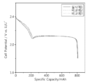
- Figure 1 illustrates a graph of the discharge capacity evaluation results of Example 1, Comparative Example 2, and Comparative Example 3 in the present specification.
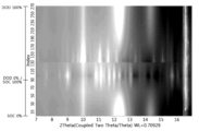
- Figure 2a illustrates the results of real-time charge/discharge XRD measurements for the lithium-sulfur battery of Example 1 in the present specification.
- Figure 2b shows the XRD pattern in the discharge state (DOD 22%) from the real-time charge/discharge XRD graph obtained in Figure 2a.
- Figure 3a illustrates the results of real-time charge/discharge XRD measurements for the lithium-sulfur battery of Comparative Example 1 in the present specification.
- Figure 3b shows the XRD pattern in the discharge state (DOD 22%) from the real-time charge/discharge XRD graph obtained in Figure 3a.
- Figure 4a illustrates the results of real-time charge/discharge XRD measurements for the lithium-sulfur battery of Comparative Example 2 in the present specification.
- Figure 4b shows the XRD pattern in the discharge state (DOD 22%) from the real-time charge/discharge XRD graph obtained in Figure 4a.
- Figure 5a illustrates the results of real-time charge/discharge XRD measurements for the lithium-sulfur battery of Comparative Example 3 in the present specification.
- Figure 5b shows the XRD pattern in the discharge state (DOD 22%) from the real-time charge/discharge XRD graph obtained in Figure 5a.
- references to 'A and/or B' mean 'A or B or both.
- temperature refers to Celsius temperature and the unit is °C.
- composite refers to a material in which two or more materials are combined to form physically and chemically different phases and exhibit more effective functions.
- (poly)sulfide as used in this specification is a concept that includes both “(poly)sulfide ion (S x 2- , 1 ⁇ x ⁇ 8)" and “lithium (poly)sulfide (Li 2 S x or Li 2 S x - 1 ⁇ x ⁇ 8)".
- polysulfide as used in this specification is a concept that includes both “polysulfide ion (S x 2- , 1 ⁇ x ⁇ 8)" and “lithium polysulfide (Li 2 S x or Li 2 S x - 1 ⁇ x ⁇ 8)".
- mAh/g s used in this specification is intended to indicate capacity per weight of sulfur (S) unless otherwise specifically stated, and may be used interchangeably with other expressions such as mAh/g(s), mAh/gs, etc.
- the unit "mg s /cm 2" used in this specification, unless otherwise specified, is intended to represent the weight of sulfur (S) per unit area, and may be used interchangeably with other expressions such as mg(s)/cm 2 or mAh/cm 2 as a loading amount.
- a lithium-sulfur battery having high energy density is provided.
- a lithium-sulfur battery comprises a cathode comprising a sulfur-carbon composite, an anode, a separator interposed between the cathode and the anode, and an electrolyte.
- the lithium-sulfur battery may include an electrode assembly including the positive electrode, negative electrode, and separator, and a case accommodating the electrolyte.
- the above lithium-sulfur battery comprises a compound having at least three characteristic peaks selected from diffraction angles (2 ⁇ values) of 7.1 ⁇ 0.2°, 9.0 ⁇ 0.2°, 9.4 ⁇ 0.2°, 9.6 ⁇ 0.2°, 9.9 ⁇ 0.2°, 10.0 ⁇ 0.2°, 10.4 ⁇ 0.2°, 11.0 ⁇ 0.2°, 11.6 ⁇ 0.2°, 12.1 ⁇ 0.2°, 13.3 ⁇ 0.2°, 14.5 ⁇ 0.2°, and 15.0 ⁇ 0.2° of an X-ray diffraction (XRD) pattern in a discharged state, particularly at a depth of discharge (DOD) of 15% to 80%.
- XRD X-ray diffraction
- the lithium-sulfur battery may include a compound having three or more characteristic peaks selected from diffraction angles (2 ⁇ values) of 7.1°, 9.0°, 9.4°, 9.6°, 9.9°, 10.0°, 10.4°, 11.0°, 11.6°, 12.1°, 13.3°, 14.5°, and 15.0° of an X-ray diffraction pattern in a discharged state.
- the lithium-sulfur battery may specifically include a compound having three or more characteristic peaks selected from diffraction angles (2 ⁇ values) of 7.1°, 9.0°, 9.4°, 9.6°, 9.9°, 10.0°, 10.4°, 11.0°, 11.6°, 12.1°, 13.3°, 14.5°, and 15.0° of an X-ray diffraction pattern at a DOD of 15% to 80%.
- a lithium-sulfur battery according to one aspect of the present invention comprises a compound having the XRD pattern in a discharged state.
- the lithium-sulfur battery includes inorganic sulfur (S 8 ) as a cathode active material.
- inorganic sulfur (S 8 ) as a cathode active material.
- lithium polysulfide is formed through a reduction reaction at the cathode during discharge.
- the compound may be a crystalline form of lithium polysulfide formed through a reduction reaction of the inorganic sulfur (S 8 ).
- the lithium-sulfur battery according to one aspect of the present invention may realize high energy density by including a crystalline form of lithium polysulfide having the XRD pattern in a discharged state.
- the compound may be a crystalline form of lithium polysulfide, wherein the lithium polysulfide may represent at least one of Li 2 S x and Li 2 S x - (1 ⁇ x ⁇ 8).
- the compound may be defined as a crystalline form of lithium polysulfide having at least three characteristic peaks among the following diffraction angles (2 ⁇ values) 7.1 ⁇ 0.2°, 9.0 ⁇ 0.2°, 9.4 ⁇ 0.2°, 9.6 ⁇ 0.2°, 9.9 ⁇ 0.2°, 10.0 ⁇ 0.2°, 10.4 ⁇ 0.2°, 11.0 ⁇ 0.2°, 11.6 ⁇ 0.2°, 12.1 ⁇ 0.2°, 13.3 ⁇ 0.2°, 14.5 ⁇ 0.2°, and 15.0 ⁇ 0.2°.
- the compound may be a crystalline form in which lithium polysulfide formed during discharge of a high-energy-density lithium-sulfur battery is formed under the high-energy-density conditions of the present invention.
- the high-energy-density lithium-sulfur battery may have a low El/S (electrolyte/sulfur) ratio as described below, and the lithium polysulfide formed during operation of the lithium-sulfur battery may be dissolved at a high concentration in a small amount of electrolyte, thereby forming a crystalline form exhibiting a diffraction angle characteristic peak of the XRD pattern.
- the formation mechanism of the compound is not limited thereto.
- the compound may have four or more, for example, five or more, characteristic peaks selected from the diffraction angles (2 ⁇ values), and specifically, may have three, four, five, six, seven, eight, nine, ten, eleven, twelve or thirteen characteristic peaks.
- the compound may have an XRD pattern having diffraction angles (2 ⁇ values) of 7.1 ⁇ 0.2°, 9.0 ⁇ 0.2°, 9.4 ⁇ 0.2°, 9.6 ⁇ 0.2°, 9.9 ⁇ 0.2°, 10.0 ⁇ 0.2°, 10.4 ⁇ 0.2°, 11.0 ⁇ 0.2°, 11.6 ⁇ 0.2°, 12.1 ⁇ 0.2°, 13.3 ⁇ 0.2°, 14.5 ⁇ 0.2°, and 15.0 ⁇ 0.2°.
- the compound may have diffraction angles (2 ⁇ values) of an XRD pattern of 7.1°, 9.0°, 9.4°, 9.6°, 9.9°, 10.0°, 10.4°, 11.0°, 11.6°, 12.1°, 13.3°, 14.5° and 15.0°.
- the compound may have an XRD pattern having diffraction angles (2 ⁇ values) of 7.1 ⁇ 0.2°, 9.0 ⁇ 0.2°, 9.4 ⁇ 0.2°, 9.6 ⁇ 0.2°, 9.9 ⁇ 0.2°, 10.0 ⁇ 0.2°, 10.4 ⁇ 0.2°, 11.0 ⁇ 0.2°, 11.6 ⁇ 0.2°, 12.1 ⁇ 0.2°, 13.3 ⁇ 0.2°, 14.5 ⁇ 0.2°, and 15.0 ⁇ 0.2°.
- the compound may have an XRD pattern having diffraction angles (2 ⁇ values) of 7.1°, 9.0°, 9.4°, 9.6°, 9.9°, 10.0°, 10.4°, 11.0°, 11.6°, 12.1°, 13.3°, 14.5°, and 15.0°.
- the compound may be included in at least one of the positive electrode, the negative electrode, the separator, the electrolyte, and the inner surface of the case of the lithium-sulfur battery, and the XRD pattern may be obtained through non-destructive analysis of the lithium-sulfur battery. That is, the XRD pattern may be measured without disassembling the lithium-sulfur battery.
- the XRD pattern can be obtained from the lithium-sulfur battery.
- the XRD pattern can be obtained through non-destructive analysis of the lithium-sulfur battery, and can be obtained, for example, through operando X-ray diffraction ( Operando XRD ) analysis.
- the error range of the 2 ⁇ value by XRD may be ⁇ 0.2°, and more specifically, may be ⁇ 0.1°.
- the XRD measurement and the charging/discharging of the lithium-sulfur battery may be performed simultaneously. Specifically, the XRD measurement may be performed continuously during the time when the lithium-sulfur battery is charged / discharged.
- the XRD pattern can be obtained from real-time charge-discharge XRD measurement results using operando X-ray diffraction.
- a pressurized jig equipped with a Be-window can be used for XRD measurement during operation of the lithium-sulfur battery, but the present invention is not limited thereto.
- the XRD pattern of the compound is obtained in the discharged state of a lithium-sulfur battery, and the discharged state in which the XRD pattern is obtained is a state of DOD (depth of discharge) of 15% to 80%.
- the state of DOD 15% to DOD 80% refers to a state in which the lithium-sulfur battery is in a fully charged state, that is, in a state of SOC (State of Charge) 100%, and is discharged to 15% to 80% of the total capacity.
- SOC State of Charge
- the XRD peak in order to facilitate detection of the characteristic peak of the compound, may be detected in any discharge state of the lithium-sulfur battery, for example, the XRD peak may be detected in a state of DOD 20% to DOD 60% or DOD 20% to DOD 50%.
- the XRD peak of the compound may be detected based on when the lithium-sulfur battery is in a DOD 22% state, but the present invention is not limited to a specific discharge state.
- the DOD 15% may be a state having a potential of 2.2 V or less, and the state of DOD 15% to DOD 80% may be a state having a potential of, for example, 1.7 V to 2.2 V, but the present invention is not limited thereto.
- the total discharge capacity of the lithium-sulfur battery may have a total capacity of 1,000 mAh/g(s) or more based on the discharge capacity per weight of sulfur (S).
- the total discharge capacity of the lithium-sulfur battery may be 1,000 mAh/g(s) to 1,300 mAh/g(s), specifically 1,100 mAh/g(s) to 1,200 mAh/g(s), for example, 1,180 mAh/g(s), based on the discharge capacity per weight of sulfur (S), and the DOD of 15% may be a state having a capacity of 15% of the total discharge capacity, and the DOD of 80% may be a state having a capacity of 80% of the total discharge capacity.
- the state of DOD 15% to DOD 80% may be a state having a capacity of 150 to 960 mAh/g(s) based on the discharge capacity per weight of sulfur (S).
- a lithium-sulfur battery including a compound having characteristic peaks in the XRD pattern as described above in a state of DOD 15% to DOD 80% can exhibit an effect of high energy density.
- the lithium-sulfur battery may have an S X value of 1.4 mAh/cm 2 or more according to the following equation 1.
- the above S PE is the loading amount of sulfur (S) in the anode
- S EL/S represents the weight ratio (El/S weight ratio) of elemental sulfur (S) in the electrolyte and the sulfur-carbon complex.
- the above S PE can be a value having a unit of mAh/cm 2 .
- S EL/S is a dimensionless value, identical to the weight ratio (El/S) of elemental sulfur (S) in the electrolyte and sulfur-carbon complex described below.
- the S X value according to the formula 1 may be 1.4 mAh/cm 2 or more, for example, 1.4 mAh/cm 2 to 10 mAh/cm 2 , specifically, 1.5 mAh/cm 2 to 6 mAh/cm 2 , more specifically, 1.6 mAh/cm 2 to 4 mAh/cm 2 , for example, 1.7 mAh/cm 2 to 2.5 mAh/cm 2 .
- the lithium-sulfur battery may include a compound having the above-described XRD peak, and thus exhibit an effect of exhibiting a high energy density, but the present invention is not limited thereto.
- the positive electrode may include a positive electrode current collector and a positive electrode active material layer applied to one or both surfaces of the positive electrode current collector.
- the above-mentioned positive electrode current collector supports the positive electrode active material, and is not particularly limited as long as it has high conductivity without causing chemical changes in the battery.
- copper, stainless steel, aluminum, nickel, titanium, palladium, calcined carbon, copper or stainless steel surface-treated with carbon, nickel, silver, etc., aluminum-cadmium alloy, etc. can be used.
- the above positive electrode current collector can form fine irregularities on its surface to strengthen the bonding strength with the positive electrode active material, and can be used in various forms such as a film, sheet, foil, mesh, net, porous body, foam, and non-woven body.
- the above positive electrode active material layer includes a positive electrode active material and may further include a conductive material, a binder, and additives.
- the positive electrode active material comprises a sulfur-carbon complex.
- the sulfur-carbon composite may include a porous carbon material; and a sulfur-based compound supported on at least one of the inside of the pores of the porous carbon material and the outer surface of the porous carbon material.
- sulfur acting as the positive electrode active material since it does not have electrical conductivity alone, it is used in a composite with a conductive material such as a carbon material, and a porous carbon material may be used to support the sulfur.
- the sulfur-based compound may be inorganic sulfur (S 8 ).
- the porous carbon material is used to support a sulfur-based compound as a positive electrode active material, and to provide a framework in which the sulfur-based compound can be uniformly and stably fixed, while improving the conductivity of the positive electrode.
- Any porous carbon material can be used without particular limitation in its type.
- the above porous carbon material can generally be manufactured by carbonizing precursors of various carbon materials.
- the porous carbon material includes pores therein that are not uniform, and the average diameter of the pores is in the range of 1 to 200 nm, and the porosity can be in the range of 10 to 90 volume% of the total volume of the porous carbon material. If the average diameter of the pores is less than the above range, the pore size is only at the molecular level, making sulfur impregnation impossible, and on the contrary, if it exceeds the above range, the mechanical strength of the porous carbon material is weakened, which is not preferable for application to a manufacturing process of an electrode.
- the 'average pore diameter' can be measured according to a method known in the art for measuring the pore diameter of a porous material, and the measuring method is not particularly limited.
- the pore diameter can be measured according to a scanning electron microscope (SEM), a field emission electron microscope (laser diffraction method), a laser diffraction method, or the BET (Brunauer-Emmett-Teller) method.
- the measurement using the laser diffraction method can be, for example, by using a commercially available laser diffraction particle size measuring device (for example, Microtrac MT 3000).
- the measurement according to the BET method can be, for example, by using an analyzer of the BELSORP series of BEL Japan, but is not limited thereto.
- the 'porosity' means the ratio of the volume occupied by pores to the total volume in a certain structure, and uses % as its unit, and can be used interchangeably with terms such as void ratio and porosity.
- the measurement of the porosity is not particularly limited, and according to one embodiment of the present invention, for example, it can be measured by the BET method using nitrogen gas or the mercury permeation method (Hg porosimeter) and ASTM D2873.
- the shape of the above porous carbon material may be spherical, rod-shaped, needle-shaped, plate-shaped, tubular or bulk-shaped, and may be used without limitation as long as it is a shape commonly used in lithium-sulfur batteries.
- the porous carbon material may be any material that is commonly used in the art and has a porous structure or a high specific surface area.
- the porous carbon material may be at least one selected from the group consisting of graphite; graphene; carbon black such as Denka black, acetylene black, Ketjen black, channel black, furnace black, lamp black, and summer black; carbon nanotubes (CNTs) such as single-walled carbon nanotubes (SWCNTs) and multi-walled carbon nanotubes (MWCNTs); carbon fibers such as graphite nanofibers (GNFs), carbon nanofibers (CNFs), and activated carbon fibers (ACFs); and graphite and activated carbon such as natural graphite, artificial graphite, and expanded graphite, but is not limited thereto.
- the porous carbon material may be a carbon nanotube.
- the porous carbon material may include, for example, carbon nanotubes (CNTs).
- the sulfur-carbon complex may have a sulfur/carbon weight ratio (S/C weight ratio) of, for example, 2.3 g/g or more.
- the sulfur-carbon complex may have a sulfur/carbon weight ratio of 2.3 g/g.
- S/C ratio of the sulfur-carbon complex is within the above-described range, it may be preferable in terms of securing the electron transfer ability (conductivity) and the electrochemical specific surface area of the sulfur-carbon complex, and for example, the available surface area of the sulfur-carbon complex increases, which may be preferable in suppressing the elution of sulfur from the anode, but the present invention is not limited thereto.
- the S/C ratio can be calculated from the weight (g) of sulfur and the weight (g) of carbon present in the sulfur-carbon complex. Alternatively, it can be calculated from the weight (wt%) of sulfur and the weight (wt%) of carbon based on the total weight of the sulfur-carbon complex. In this way, the S/C ratio can be a unitless value.
- the S/C weight ratio may have a value of, for example, 0.5 to 5.0, 0.5 to 4.0, 1.0 to 3.0, 1.5 to 2.5, 2.0 to 2.45, 2.25 to 2.35, or 2.3 to 3.
- the S/C ratio may be calculated from the weight ratio of the inorganic sulfur (S 8 )/the weight ratio of the porous carbon material.
- the S/C ratio may be calculated from the weight ratio of S 8 /CNT.
- the method for producing the above sulfur-carbon complex is not particularly limited in the present invention, and a method commonly used in the art may be used. For example, a method of simply mixing the sulfur and the porous carbon material and then heat-treating them to form a composite may be used.
- the above-mentioned positive electrode active material may further include at least one selected from a transition metal element, a group IIIA element, a group IVA element, a sulfur compound of these elements, and an alloy of these elements and sulfur.
- the above transition metal elements include Sc, Ti, V, Cr, Mn, Fe, Co, Ni, Cu, Zn, Y, Zr, Nb, Mo, Tc, Ru, Rh, Pd, Os, Ir, Pt, Au or Hg
- the above group IIIA elements include Al, Ga, In, Ti
- the above group IVA elements may include Ge, Sn, Pb, the above group IVA elements.
- the sulfur-carbon complex may be at least 50 wt% based on the total weight of the positive electrode. Specifically, the sulfur-carbon complex may be at least 80 wt%, at least 90 wt%, or at least 95 wt% based on the total weight of the positive electrode active material layer. Specifically, the sulfur-carbon complex may be included in an amount of 80 wt% to 100 wt%, more specifically 85 wt% to 99 wt%, 90 wt% to 99 wt%, 95 wt% to 98 wt%, or 95 wt% to 97 wt%, or 96 wt% based on the total weight of the positive electrode active material layer.
- the content of the above sulfur-carbon complex is below the above range, the relative content of auxiliary materials such as a conductive material and a binder increases and the content of the sulfur-carbon complex decreases, making it difficult to implement a high-capacity, high-energy-density battery.
- auxiliary materials such as a conductive material and a binder
- the content of the sulfur-carbon complex decreases, making it difficult to implement a high-capacity, high-energy-density battery.
- it exceeds the above range there is a problem that the physical properties of the electrode deteriorate due to the relatively insufficient content of the conductive material or binder described below.
- the above-mentioned conductive material is a material that electrically connects the electrolyte and the positive electrode active material and acts as a path for electrons to move from the current collector to the positive electrode active material.
- Any conductive material that is physically distinct from the carbon contained in the sulfur-carbon complex and is a component of the electrode can be used without limitation.
- the conductive material may be, for example, carbon black such as Super-P, Denka black, acetylene black, Ketjen black, channel black, furnace black, lamp black, summer black, carbon black; carbon derivatives such as carbon nanotubes or fullerene; conductive fibers such as carbon fibers or metal fibers; metal powders such as fluorinated carbon, aluminum, and nickel powder; or conductive polymers such as polyaniline, polythiophene, polyacetylene, and polypyrrole, which may be used alone or in combination.
- carbon black such as Super-P, Denka black, acetylene black, Ketjen black, channel black, furnace black, lamp black, summer black, carbon black
- carbon derivatives such as carbon nanotubes or fullerene
- conductive fibers such as carbon fibers or metal fibers
- metal powders such as fluorinated carbon, aluminum, and nickel powder
- conductive polymers such as polyaniline, polythiophene, polyacetylene, and polypyrrole
- the content of the conductive material may be 0 to 40 wt%, for example, 1 to 40 wt%, 15 to 40 wt%, 20 to 40 wt%, or 25 to 35 wt%, or 0 to 10 wt%, for example, 1 to 10 wt%, based on the total weight of the positive electrode active material layer. If the content of the conductive material is less than the above range, electron transfer between the positive electrode active material and the current collector may not be easy, which may cause a decrease in voltage and capacity. On the contrary, if it exceeds the above range, the proportion of the positive electrode active material may relatively decrease, which may cause a decrease in the total energy (charge) of the battery. Therefore, it is preferable to determine an appropriate content within the above-mentioned range.
- the binder maintains the positive electrode active material on the positive electrode current collector and organically connects the positive electrode active materials to increase the bonding strength therebetween, and any binder known in the art can be used.
- the binder may be a fluororesin binder including polyvinylidene fluoride (PVdF), a polyvinylidene fluoride polymer including at least one vinylidene fluoride as a repeating unit, polytetrafluoroethylene (PTFE), or a mixture of two or more thereof; a rubber binder including styrene butadiene rubber (SBR), acrylonitrile-butadiene rubber, or styrene-isoprene rubber; an acrylic binder; a cellulose binder including carboxyl methyl cellulose (CMC), starch, hydroxy propyl cellulose, or regenerated cellulose; a polyalcohol binder; a polyolefin binder including polyethylene and polypropylene; a polyimide binder; a polyester binder; a silane binder; a polyacrylic acid binder; And a polyacrylonitrile-based binder; a mixture or copolymer of one or Vd
- the content of the binder may be 1 to 10 wt% based on the total weight of the positive electrode active material layer. If the content of the binder is less than the above range, the physical properties of the positive electrode may deteriorate, causing the positive electrode active material and the conductive material to fall off, and if the content of the binder is more than the above range, the ratio of the positive electrode active material and the conductive material in the positive electrode may relatively decrease, thereby reducing the battery capacity. Therefore, it is preferable to determine an appropriate content within the above-described range.
- the method for manufacturing the positive electrode for a lithium secondary battery is not particularly limited, and various methods known to those skilled in the art or modified methods thereof can be used.
- the positive electrode for the lithium secondary battery may be manufactured by forming the positive electrode active material layer by preparing a positive electrode slurry composition including the composition described above and then applying the same to at least one surface of the positive electrode current collector.
- the above positive electrode slurry composition includes the positive electrode active material described above, and may further include a binder, a conductive material, and a solvent.
- the above solvent is used that can evenly disperse the positive electrode active material.
- water is most preferable as an aqueous solvent, and in this case, the water can be distilled water or deionized water.
- a lower alcohol that can be easily mixed with water can be used.
- the lower alcohol includes methanol, ethanol, propanol, isopropanol, and butanol, and preferably, these can be used by mixing with water.
- the content of the above solvent may be contained at a level that has a concentration that can facilitate coating, and the specific content varies depending on the application method and device.
- the above-mentioned positive electrode slurry composition may additionally contain, if necessary, substances commonly used in the relevant technical field for the purpose of improving its function, etc. Examples thereof include viscosity modifiers, fluidizing agents, and fillers.
- the method for applying the above positive electrode slurry composition is not particularly limited in the present invention, and for example, methods such as doctor blade, die casting, comma coating, and screen printing can be mentioned.
- the positive electrode slurry may be applied onto the positive electrode current collector by molding it on a separate substrate and then pressing or lamination.
- a drying process for removing the solvent can be performed.
- the drying process is performed at a temperature and time that can sufficiently remove the solvent, and the conditions may vary depending on the type of solvent and are therefore not particularly limited to the present invention. For example, drying by warm air, hot air, low-humidity air, vacuum drying, and drying by irradiation with (far) infrared rays and electron beams can be mentioned.
- the drying speed is usually adjusted so that the solvent can be removed as quickly as possible within a speed range that does not cause cracks in the positive electrode active material layer due to stress concentration or does not cause the positive electrode active material layer to peel off from the positive electrode current collector.
- the density of the positive electrode active material in the positive electrode can be increased by pressing the entire body after the drying. Pressing methods include mold pressing and roll pressing.
- the porosity of the positive electrode manufactured by the composition and manufacturing method described above, specifically, the positive electrode active material layer may be 50 to 80% by volume, specifically, 60 to 75% by volume.
- the filling degree of the positive electrode slurry composition including the positive electrode active material, the conductive agent, and the binder becomes excessively high, so that sufficient electrolyte capable of exhibiting ionic conductivity and/or electrical conductivity cannot be maintained between the positive electrode active materials, which may deteriorate the output characteristics or cycle characteristics of the battery, and there is a problem that the overvoltage and discharge capacity of the battery decrease significantly.
- the porosity of the positive electrode exceeds 80% by volume and has excessively high porosity, there is a problem that the physical and electrical connection with the current collector is lowered, which reduces the adhesive force and makes the reaction difficult, and the increased porosity may be filled with electrolyte, which may lower the energy density of the battery, and therefore, the porosity is appropriately controlled within the above range.
- the positive electrode may have a sulfur (S) loading of 2 to 5 mAh/cm 2 .
- the sulfur (S) loading of the positive electrode may be 2.5 to 5 mAh/cm 2 , 3 to 4 mAh/cm 2 , or 3.5 to 4 mAh/cm 2 . Or it can be 3.5 to 5 mAh/cm 2 , 3.6 to 5 mAh/cm 2 , 3.7 to 4.5 mAh/cm 2 , more specifically 3.7 to 4.0 mAh/cm 2 , but the present invention is not limited thereto.
- the sulfur loading amount in the positive electrode is in the above-described range, it can exhibit a beneficial effect in providing a lithium-sulfur battery having a high energy density, but the present invention is not limited thereto.
- the above sulfur loading amount may be a value calculated from the total weight of sulfur (S) included as a positive electrode active material in the positive electrode and the capacity value of the electrode calculated therefrom.
- the weight of sulfur in the positive electrode may be measured from the positive electrode active material introduced during the manufacturing step.
- the weight of sulfur in the positive electrode may be measured through thermal gravimetric analysis (TGA) of the positive electrode after the positive electrode is manufactured. Meanwhile, when disassembling a manufactured lithium-sulfur battery, a charged lithium-sulfur battery is disassembled under an inert atmosphere to obtain a positive electrode, and then the positive electrode is washed and dried using an appropriate washing solvent, and then the positive electrode active material layer is scraped off.
- the content of sulfur (S) derived from the active material may be measured and calculated through thermal gravimetric analysis (TGA) of the obtained result, but the measurement method is not limited thereto.
- the above negative electrode may include a negative electrode current collector and a negative electrode active material layer applied to one or both surfaces of the negative electrode current collector.
- the negative electrode may be a lithium metal plate.
- the above negative current collector is for supporting the negative active material layer, as described in the positive current collector.
- the above-mentioned negative electrode active material layer may include a conductive material, a binder, etc. in addition to the negative electrode active material. At this time, the conductive material and the binder follow the above-mentioned.
- the above negative electrode active material may include a material capable of reversibly intercalating or deintercalating lithium (Li + ), a material capable of reversibly forming a lithium-containing compound by reacting with lithium ions, lithium metal, or a lithium alloy.
- the material capable of reversibly inserting or de-inserting the lithium ion (Li + ) may be, for example, crystalline carbon, amorphous carbon, or a mixture thereof.
- the material capable of reversibly forming a lithium-containing compound by reacting with the lithium ion (Li + ) may be, for example, tin oxide, titanium nitrate, or silicon.
- the lithium alloy may be, for example, an alloy of a metal selected from the group consisting of lithium (Li) and sodium (Na), potassium (K), rubidium (Rb), cesium (Cs), francium (Fr), beryllium (Be), magnesium (Mg), calcium (Ca), strontium (Sr), barium (Ba), radium (Ra), aluminum (Al), and tin (Sn).
- a metal selected from the group consisting of lithium (Li) and sodium (Na), potassium (K), rubidium (Rb), cesium (Cs), francium (Fr), beryllium (Be), magnesium (Mg), calcium (Ca), strontium (Sr), barium (Ba), radium (Ra), aluminum (Al), and tin (Sn).
- the negative active material may be lithium metal, and specifically, may be in the form of a lithium metal thin film or lithium metal powder.
- the negative electrode may have a thickness of 40 to 80 ⁇ m.
- the thickness of the negative electrode may be 50 to 70 ⁇ m, or 60 ⁇ m.
- the thickness of the negative electrode may be measured by a known means for measuring the thickness of each component of the battery, and may be measured using a thickness measuring device from Mitutoyo, for example, but is not limited thereto.
- the thickness of the negative electrode may be measured according to ASTM D374.
- the above separator separates or insulates the positive and negative electrodes from each other and enables lithium ion transport between the positive and negative electrodes. It may be made of a porous non-conductive or insulating material, and if it is commonly used as a separator in a lithium secondary battery, it may be used without special restrictions.
- the separator may be an independent member such as a film, or may be a coating layer added to the positive and/or negative electrodes.
- the above-mentioned separator have low resistance to ion movement of the electrolyte and excellent moisture retention capacity for the electrolyte.
- the separator may include a porous substrate, and any porous substrate typically used in secondary batteries may be used as the porous substrate, and a porous polymer film may be used alone or in a laminated manner.
- a nonwoven fabric or a polyolefin-based porous film made of high-melting-point glass fibers, polyethylene terephthalate fibers, or the like may be used, but is not limited thereto.
- the porous substrate is not particularly limited in the present invention, and any porous substrate commonly used in electrochemical devices can be used.
- the porous substrate may be a polyolefin such as polyethylene, polypropylene, etc., a polyester such as polyethyleneterephthalate, polybutyleneterephthalate, polyamide, polyacetal, polycarbonate, polyimide, polyetheretherketone, polyethersulfone, polyphenyleneoxide, polyphenylenesulfide, polyethylenenaphthalate, polytetrafluoroethylene, polyvinylidene fluoride, polyvinyl chloride, polyacrylonitrile, cellulose, nylon, It may include at least one material selected from the group consisting of poly(p-phenylene benzobisoxazole) and polyarylate.
- the thickness of the porous substrate is not particularly limited, but may be 1 to 100 ⁇ m, preferably 5 to 50 ⁇ m.
- the thickness range of the porous substrate is not limited to the above-mentioned range, but if the thickness is excessively thinner than the above-mentioned lower limit, the mechanical properties may deteriorate, and the separator may be easily damaged during use of the battery.
- the average diameter and porosity of the pores present in the porous substrate are not particularly limited, but may be 0.001 to 50 ⁇ m and 10 to 95 volume%, respectively.
- the separator may further include a porous coating layer formed on at least one surface of the porous substrate and including inorganic particles and a binder.
- the inorganic particles and binder included in the porous coating layer may be used without particular limitation as long as they are commonly used in the porous coating layer of a separation membrane, and the manufacturing method thereof is also not particularly limited.
- the above electrolyte comprises a non-aqueous solvent as a medium through which ions involved in the electrochemical reaction of a lithium-sulfur battery can move, and a lithium salt as an electrolyte.
- the above electrolyte is not particularly limited as long as it has a composition that can be used in a lithium secondary battery, specifically a lithium-sulfur battery.
- the electrolyte may include a non-aqueous solvent, a lithium salt, and an additive.
- the non-aqueous solvent may be used without particular limitation as long as it is of a type that can be used in a lithium-sulfur battery, and for example, ether solvents, esters, amides, linear carbonates, and cyclic carbonates may be used.
- the ester may be, for example, one selected from the group consisting of methyl acetate, ethyl acetate, propyl acetate, methyl propionate, ethyl propionate, propyl propionate, ⁇ -butyrolactone, ⁇ -valerolactone, ⁇ -caprolactone, ⁇ -valerolactone, and ⁇ -caprolactone, or a mixture of two or more thereof, but is not limited thereto.
- the linear carbonate may be, for example, one selected from the group consisting of dimethyl carbonate, diethyl carbonate, dipropyl carbonate, ethylmethyl carbonate, methylpropyl carbonate, and ethylpropyl carbonate, or a mixture of two or more thereof, but is not limited thereto.
- the cyclic carbonate is, for example, one selected from the group consisting of ethylene carbonate, propylene carbonate, 1,2-butylene carbonate, 2,3-butylene carbonate, 1,2-pentylene carbonate, 2,3-pentylene carbonate, vinylene carbonate, vinylethylene carbonate, and halogenides thereof, or a mixture of two or more thereof.
- halogenides thereof include, but are not limited to, fluoroethylene carbonate.
- the non-aqueous solvent may include an ether solvent.
- the ether solvent may be included in an amount of 60 vol% or more, for example, 60 vol% to 100 vol%, 70 vol% to 100 vol%, 80 vol% to 100 vol%, 85 vol% to 100 vol%, 90 vol% to 100 vol%, 95 vol% to 100 vol%, 98 vol% to 100 vol%, 90 vol% to 98 vol%, or 90 vol% to 95 vol%, based on the total volume of the non-aqueous solvent.
- the content of the ether solvent is within the above-described range based on the total volume of the non-aqueous solvent, a beneficial effect may be exhibited in terms of the solubility of the electrolyte composition such as a lithium salt, but the present invention is not limited thereto.
- the ether solvent may include an acyclic ether, a cyclic ether, or a mixture thereof.
- the acyclic ether is selected from the group consisting of, for example, dimethyl ether, diethyl ether, dipropyl ether, dibutyl ether, diisobutyl ether, ethyl methyl ether, ethylpropyl ether, ethyl tertbutyl ether, dimethoxymethane, trimethoxymethane, dimethoxyethane, diethoxyethane, dimethoxypropane, diethylene glycol dimethyl ether, diethylene glycol diethyl ether, triethylene glycol dimethyl ether, tetraethylene glycol dimethyl ether, ethylene glycol divinyl ether, diethylene glycol divinyl ether, triethylene glycol divinyl ether, dipropylene glycol dimethylene ether, butylene glycol ether, diethylene glycol ethyl methyl ether, diethylene glycol isopropyl methyl ether, di
- It may include one or more kinds.
- it may include one or more kinds selected from the group consisting of dimethyl ether, dimethoxyethane, diethoxyethane, diethylene glycol dimethyl ether, triethylene glycol dimethyl ether, and tetraethylene glycol dimethyl ether, and more preferably, it may include dimethoxyethane.
- the cyclic ether is, for example, 2-methylfuran, 1,3-dioxolane, 4,5-dimethyl-dioxolane, 4,5-diethyl-dioxolane, 4-methyl-1,3-dioxolane, 4-ethyl-1,3-dioxolane, tetrahydrofuran, 2-methyltetrahydrofuran, 2,5-dimethyltetrahydrofuran, 2,5-dimethoxytetrahydrofuran, 2-ethoxytetrahydrofuran, 2-methyl-1,3-dioxolane, 2-vinyl-1,3-dioxolane, 2,2-dimethyl-1,3-dioxolane, 2-methoxy-1,3-dioxolane, 2-ethyl-2-methyl-1,3-dioxolane, tetrahydropyran, 1,4-dioxane, It may include at least one
- it may include at least one selected from the group consisting of 2-methylfuran, 1,3-dioxolane, tetrahydrofuran, 2-methyltetrahydrofuran, and 2,5-dimethyltetrahydrofuran, and more preferably, it may include 2-methylfuran.
- the non-aqueous solvent may include a mixture of an acyclic ether and a cyclic ether.
- the non-aqueous solvent may include dimethoxyethane (DME) and 2-methylfuran (2-MeF).
- DME dimethoxyethane
- 2-MeF 2-methylfuran
- the volume ratio of the acyclic ether and the cyclic ether may be 5:95 to 95:5 (v/v), specifically 95:5 to 50:50, more specifically 90:10 to 70:30, 85:15 to 75:25 or 80:20.
- the volume ratio corresponds to the ratio of "volume % of acyclic ether”: "volume % of cyclic ether” in the ether solvent.
- the non-aqueous solvent may not contain a carbonate solvent in terms of the solubility of the electrolyte.
- the non-aqueous solvent may contain a very small amount of a carbonate solvent such that the carbonate solvent does not affect the solubility of the lithium salt.
- the content of the carbonate solvent may be 3 wt% or less, 2 wt% or less, 1 wt% or less, 0.5 wt% or less, or 0 wt% (i.e., not contained at all) based on the total weight of the electrolyte for a lithium secondary battery.
- the lithium salt may be used without particular limitation as long as it can be used as an electrolyte of a lithium secondary battery.
- the lithium salt may be, for example, LiCl, LiBr, LiI, LiClO 4 , LiBF 4 , LiB 10 Cl 10 , LiPF 6 , LiCF 3 SO 3 , LiCF 3 CO 2 , LiC 4 BO 8 , LiAsF 6 , LiSbF 6 , LiAlCl 4 , CH 3 SO 3 Li, CF 3 SO 3 Li, (CF 3 SO 2 ) 2 NLi, (C 2 F 5 SO 2 ) 2 NLi, (SO 2 F) 2 NLi, (CF 3 SO 2 ) 3 CLi, lithium chloroborane, lithium lower aliphatic carboxylic acid, lithium 4-phenylborate, lithium imide, or one containing two or more thereof.
- the concentration of the lithium salt may be appropriately determined in consideration of ion conductivity, solubility, etc., and may be, for example, 0.1 to 4 M, preferably 0.5 to 2 M.
- concentration of the lithium salt is within the above-described range, it is advantageous in securing ion conductivity suitable for battery operation, or may exhibit advantageous effects in terms of improving the mobility of lithium ions and suppressing the decomposition reaction of the lithium salt itself by exhibiting an appropriate viscosity of the electrolyte, but the present invention is not limited thereto.
- the additive may include a nitrogen compound in addition to the lithium salt to improve the electrical conductivity of the electrolyte and to improve the lifespan of the lithium-sulfur battery.
- the nitrogen compound may, for example, inhibit the reduction reaction of polysulfide that occurs during the charge/discharge process of a lithium-sulfur battery, thereby preventing irreversible consumption of polysulfide, and thereby improving the performance of a lithium-sulfur battery, although its efficacy is not limited thereto.
- the nitrogen compound may be used without particular limitation as long as it has the effect of stably forming a solid electrolyte membrane (SEI) of the negative electrode and improving charge/discharge efficiency, and may be, for example, a nitric acid compound, a nitrite compound, or a mixture thereof.
- SEI solid electrolyte membrane
- the nitrogen compound is an inorganic nitric or nitrous compound, such as lithium nitrate (LiNO 3 ), potassium nitrate (KNO 3 ), cesium nitrate (CsNO 3 ), barium nitrate (Ba(NO 3 ) 2 ), ammonium nitrate (NH 4 NO 3 ), lithium nitrite (LiNO 2 ), potassium nitrite (KNO 2 ), cesium nitrite (CsNO 2 ), and ammonium nitrite (NH 4 NO 2 ); an organic nitric or nitrous compound, such as methyl nitrate, dialkyl imidazolium nitrate, guanidine nitrate, imidazolium nitrate, pyridinium nitrate, ethyl nitrite, propyl nitrite, butyl nitrite, pentyl nitrite, and octyl nitrite
- the nitrogen compound may be included in an amount of, for example, 1 wt% to 10 wt%, 2 wt% to 10 wt%, or 3 wt% to 10 wt%, specifically 3 wt% to 8 wt%, 3 wt% to 6 wt%, or 3 wt% to 5 wt%, based on the total weight of the electrolyte, but is not limited thereto.
- the nitrogen compound may exhibit more advantageous effects in terms of improving the electrical conductivity of the electrolyte and suppressing reduction of polysulfide when used in a lithium-sulfur battery, but the present invention is not limited thereto.
- the lithium-sulfur battery may have a weight ratio of sulfur (S) in the sulfur-carbon complex of the electrolyte and the positive electrode (El/S weight ratio) of 2.5 g/g or less in order to achieve high energy density.
- the El/S ratio of the lithium-sulfur battery may be 1.5 to 2.5 g/g, specifically 2 to 2.5 g/g, 2 to 2.3 g/g, 2.0 to 2.2 g/g or 2.0 to 2.15 g/g.
- the El/S ratio of the lithium-sulfur battery can be calculated by the ratio of the weight of sulfur in the sulfur-carbon composite of the positive electrode introduced in the manufacturing step immediately after the manufacture of the lithium-sulfur battery and the weight of the introduced electrolyte.
- the El/S ratio of the lithium-sulfur battery can be calculated by the ratio of the weight of sulfur in the sulfur-carbon complex of the cathode analyzed by disassembling the battery and the weight of the electrolyte introduced.
- the lithium-sulfur battery is measured for its total weight in a charged state, then disassembled, and the positive electrode, negative electrode, separator, and case are washed and dried with a solvent to obtain the sum of their respective weights, and the weight of the electrolyte is measured by deducting the weight of the positive electrode, negative electrode, separator, and case from the measured total weight of the battery.
- a solvent for the washing that can extract the electrolyte contained in the positive electrode, negative electrode, separator, and case.
- the positive electrode active material layer and the current collector are separated from the dried positive electrode, and then the weight of sulfur derived from the sulfur-carbon complex present in the positive electrode active material layer is measured, thereby measuring the weight of sulfur in the positive electrode.
- the El/S ratio of the lithium-sulfur battery can be calculated by the ratio of the weight of sulfur in the sulfur-carbon complex of the positive electrode obtained in this way to the weight of the introduced electrolyte.
- a method for measuring the weight of sulfur derived from a sulfur-carbon complex present in the positive electrode active material layer may be, for example, measuring the content of sulfur (S) derived from the active material through thermal gravimetric analysis (TGA) on the result obtained by scraping off the obtained positive electrode active material layer, but the measuring method is not limited thereto.
- the state of charge at which the lithium-sulfur battery is decomposed may be a full charge state, i.e., an SOC of 100%.
- the state of charge at which the lithium-sulfur battery is decomposed may be between SOC 95% and SOS 100%.
- disassembling the lithium-sulfur battery in the charged state when disassembling the lithium-sulfur battery in the charged state, it should be performed under an inert atmosphere from a safety perspective.
- disassembly of the lithium-sulfur battery can be performed under an Ar atmosphere.
- the energy density of the lithium-sulfur battery may be, for example, 400 Wh/kg or more.
- the energy density of the lithium-sulfur battery may be 420 Wh/kg or more, more specifically, 430 Wh/kg or more.
- the energy density of the lithium-sulfur battery may be 400 Wh/kg to 1,000 Wh/kg, specifically, 410 Wh/kg to 800 Wh/kg, 420 Wh/kg to 600 Wh/kg, specifically, 430 Wh/kg to 550 Wh/kg.
- the energy density of the lithium-sulfur battery may be measured according to a known method for measuring the energy density, and the measuring method is not particularly limited.
- the energy density of the lithium-sulfur battery may be calculated according to the following formula based on the specific capacity measured by discharging and charging at 0.1C at least once in the range of 1.8 V to 2.7 V at room temperature.
- the initial discharge and charge may be performed at a rate of 0.1 C to 0.3 C, respectively.
- the initial discharge and charge may be performed at a rate of 0.1 C to 0.2 C, respectively, for example, at a rate of 0.1 C.
- the initial discharge and charge may be performed three times each at a rate of 0.1C.
- the discharge capacity can be measured in mAh
- the driving voltage can be measured in V
- the cell weight can be measured in kg.
- the room temperature may be, for example, a temperature of 23°C to 25°C, and specifically, may be measured at 23°C.
- the charge/discharge rate may be 0.1 C rate to 0.5 C rate, and for example, charging and discharging may be performed at 0.3 C rate, but is not particularly limited thereto as long as charging and discharging are performed within the above-described rate range.
- the lithium-sulfur battery may have various shapes, for example, a pouch shape or a cylindrical shape, but is not limited thereto.
- a method for evaluating the energy density of a lithium-sulfur battery through a diffraction angle of an XRD pattern for the lithium-sulfur battery is provided.
- the lithium-sulfur battery to be evaluated may include a cathode comprising a sulfur-carbon composite, an anode, a separator interposed between the cathode and the anode, and an electrolyte.
- the lithium-sulfur battery may include an electrode assembly comprising the cathode, the anode, and the separator, and a case accommodating the electrolyte.
- the above evaluation method includes a step of determining a lithium-sulfur battery including a compound having three or more characteristic peaks selected from diffraction angles (2 ⁇ values) of 7.1 ⁇ 0.2°, 9.0 ⁇ 0.2°, 9.4 ⁇ 0.2°, 9.6 ⁇ 0.2°, 9.9 ⁇ 0.2°, 10.0 ⁇ 0.2°, 10.4 ⁇ 0.2°, 11.0 ⁇ 0.2°, 11.6 ⁇ 0.2°, 12.1 ⁇ 0.2°, 13.3 ⁇ 0.2°, 14.5 ⁇ 0.2°, and 15.0 ⁇ 0.2° of an X-ray diffraction (XRD) pattern at a DOD of 15% to 80% as a battery having a high energy density.
- XRD X-ray diffraction
- the XRD pattern may be obtained from real-time charge/discharge XRD measurement results for a lithium-sulfur battery.
- the evaluation method may be to obtain and evaluate XRD results in real time while charging the lithium-sulfur battery to a full state (SOC 100%) at 0.1 C to 0.3 C, for example, 0.2, and then discharging it at 0.05 C to 0.2 C, for example, 0.1 C.
- the DOD 15% to DOD 80% may have a potential of 1.7 V to 2.2 V.
- the DOD of 15% to 80% may have a discharge capacity per weight of sulfur (S) of 150 to 960 mAh/g(s).
- the battery having the high energy density may be, for example, a battery having an energy density of 300 Wh/kg or more, specifically, 430 Wh/kg or more.
- the lithium-sulfur battery may be a battery having an energy density of 400 Wh/kg to 1,000 Wh/kg, specifically, 410 Wh/kg to 800 Wh/kg, 420 Wh/kg to 600 Wh/kg, specifically, 430 Wh/kg to 550 Wh/kg.
- the positive electrode slurry composition was applied to an aluminum current collector and then dried to prepare a positive electrode.
- the sulfur (S) loading of the prepared positive electrode was 3.7 mAh/cm 2 .
- Lithium metal with a thickness of 60 ⁇ m was used as the cathode.
- An electrode assembly was prepared by positioning the positive and negative electrodes so that they face each other and interposing a polyethylene separator having a thickness of 12 ⁇ m and a porosity of 46 vol% between them.
- the prepared electrode assembly was placed in a pouch-type case and an electrolyte solution containing 0.75 M lithium salt (LiTFSI) and 3 wt% lithium nitrate (LiNO 3 ) dissolved in a solvent mixed with dimethoxyethane (DME):2-methyl furan (2-MeF) in a volume ratio of 8:2 was injected so that the El/S ratio became 2.15 g/g, thereby manufacturing a lithium-sulfur battery.
- LiTFSI lithium salt
- LiNO 3 lithium nitrate
- DME dimethoxyethane
- 2-MeF 2-methyl furan
- a lithium-sulfur battery was manufactured in the same manner as in Example 1, except that the sulfur (S) loading of the positive electrode was 2.7 mAh/cm 2 and the El/S ratio was 2.9 g/g.
- a lithium-sulfur battery was manufactured in the same manner as in Example 1, except that the sulfur (S) loading of the positive electrode was 3.5 mAh/cm 2 and the El/S ratio was 2.60 g/g.
- a lithium-sulfur battery was manufactured in the same manner as in Example 1, except that the sulfur (S) loading of the positive electrode was 3.5 mAh/cm 2 and the El/S ratio was 3.00 g/g.
- Each of the lithium-sulfur batteries manufactured in Example 1 and Comparative Examples 1 to 3 above was discharged and charged at 0.1 C in the range of 1.8 V to 2.7 V at room temperature (23°C) three times, and then the specific capacity of the battery was measured under 0.1 C discharge conditions, from which the energy density (Wh/kg) of the battery was evaluated.
- the above S PE is the loading amount of sulfur (S) in the anode
- S EL/S represents the weight ratio (El/S weight ratio) of elemental sulfur (S) in the electrolyte and the sulfur-carbon complex.
- FIG. 1 shows the results of evaluating the capacity of the batteries of Example 1, Comparative Example 2, and Comparative Example 3, and the energy density was calculated according to the following formula, and the energy densities of Example 1 and Comparative Examples 1 to 3 are shown in Table 1.
- Example 1 and Comparative Example 1 were activated by discharging to 1.8 V at 0.1 C at room temperature (23°C), then charged to 2.7 V at 0.2 C, and then discharged from 2.7 V to 1.8 V at 0.1 C rate to obtain real-time charge/discharge XRD patterns.
- XRD measurements were performed using a pressurized jig equipped with a Be-window.
- Fig. 2a Example 1
- Fig. 3a Comparative Example 1
- Fig. 4a Comparative Example 2
- Fig. 5a Comparative Example 3
- the left side of the measurement result images of Figs. 2a, 3a, 4a, and 5a shows the charge start state (SOC 0%) to the full charge state (SOC 100%) and the discharge start state (DOD 0%) to the full discharge state (DOD 100%), respectively.
- Example 1 exhibited a characteristic peak that was not detected in Comparative Examples 1 to 3 in the discharge state. Specifically, it was confirmed that Example 1 exhibited a characteristic peak that was not detected in Comparative Examples 1 to 3 in the range of DOD 15% (Index approximately 130) to DOD 80% (Index approximately 230).
- Example 1 XRD patterns at DOD 22% were obtained from the real-time charge/discharge XRD measurement results for each of the batteries of Comparative Examples 1 to 3, and are shown in FIG. 2b (Example 1), FIG. 3b (Comparative Example 1), FIG. 4b (Comparative Example 2), and FIG. 5b (Comparative Example 3).
- Example 1 (2 ⁇ values): 7.1°, 9.0°, 9.4°, 9.6°, 9.9°, 10.0°, 10.4°, 11.0°, 11.6°, 12.1°, 13.3°, 14.5°, 15.0°
- FIG. 3b Comparative Example 1
- FIG. 4b Comparative Example 2
- FIG. 5b Comparative Example 3
- Fig. 1 which compares the discharge profiles of Example 1, Comparative Example 2, and Comparative Example 3, no significant difference in discharge capacity was confirmed between them, but in the XRD patterns described in Figs. 2 to 5, it was confirmed that only Example 1 detected a specific crystalline reactant.
- Example 1 had 440 Wh/kg
- Comparative Examples 2 and 3 had 420 Wh/kg and 400 Wh/kg, respectively, despite having similar levels of discharge capacity, they had differences in energy density.
- Example 1 in which the Sx value according to Equation 1 was 1.4 mAh/cm 2 or higher, and it was confirmed that the battery according to Example 1 could exhibit a high energy density by maintaining high reactivity even though a solid-state reaction occurred within the battery.
Landscapes
- Chemical & Material Sciences (AREA)
- Chemical Kinetics & Catalysis (AREA)
- Electrochemistry (AREA)
- General Chemical & Material Sciences (AREA)
- Engineering & Computer Science (AREA)
- Manufacturing & Machinery (AREA)
- Inorganic Chemistry (AREA)
- Materials Engineering (AREA)
- Composite Materials (AREA)
- Battery Electrode And Active Subsutance (AREA)
- Secondary Cells (AREA)
Abstract
Description
| 양극 로딩량(mAh/cm2) | El/S 비율(g/g) | SX(mAh/cm2) | 에너지 밀도(Wh/kg) | |
| 실시예 1 | 3.7 | 2.15 | 1.72 | 440 |
| 비교예 1 | 2.7 | 2.9 | 1.35 | 350 |
| 비교예 2 | 3.5 | 2.60 | 1.17 | 420 |
| 비교예 3 | 3.5 | 3.00 | 0.93 | 400 |
Claims (15)
- 황-탄소 복합체를 포함하는 양극, 음극, 상기 양극 및 상기 음극 사이에 개재된 분리막 및 전해액을 포함하는 리튬-항 전지로서,DOD 15% 내지 DOD 80%에서 X선 회절(XRD) 패턴의 회절각(2θ 값) 7.1 ± 0.2°, 9.0 ± 0.2°, 9.4 ± 0.2°, 9.6 ± 0.2°, 9.9 ± 0.2°, 10.0 ± 0.2°, 10.4 ± 0.2°, 11.0 ± 0.2°, 11.6 ± 0.2°, 12.1 ± 0.2°, 13.3 ± 0.2°, 14.5 ± 0.2°및 15.0 ± 0.2°중에서 선택되는 3개 이상의 특징적인 피크를 갖는 화합물을 포함하는 리튬-황 전지.
- 청구항 1에 있어서,상기 DOD 15% 내지 DOD 80%는 1.7 V 내지 2.2 V의 전위를 갖는 상태인 리튬-황 전지.
- 청구항 1에 있어서,상기 DOD 15% 내지 DOD 80%는 150 내지 960 mAh/g(s)의 황(S) 무게 당 방전 용량을 갖는 상태인 리튬-황 전지.
- 청구항 1에 있어서,상기 화합물은 상기 열거된 회절각 중에서 선택되는 4개 이상의 특징적인 피크를 갖는 것을 리튬-황 전지.
- 청구항 1에 있어서,상기 화합물은 X선 회절(XRD) 패턴의 회절각(2θ 값) 7.1 ± 0.2°, 9.0 ± 0.2°, 9.4 ± 0.2°, 9.6 ± 0.2°, 9.9 ± 0.2°, 10.0 ± 0.2°, 10.4 ± 0.2°, 11.0 ± 0.2°, 11.6 ± 0.2°, 12.1 ± 0.2°, 13.3 ± 0.2°, 14.5 ± 0.2° 및 15.0 ± 0.2°을 포함하는 리튬-황 전지.
- 청구항 1에 있어서,상기 황-탄소 복합체는 황/탄소의 중량 비율(S/C weight ratio)이 2.3 g/g 이상인 리튬-황 전지.
- 청구항 1에 있어서,상기 양극은 집전체, 및 상기 집전체의 적어도 일면에 형성되고 상기 황-탄소 복합체를 포함하는 양극 활물질층을 포함하고,상기 양극 활물질층 총 중량을 기준으로 상기 황-탄소 복합체의 중량이 90 중량% 이상인 리튬-황 전지.
- 청구항 1에 있어서,상기 양극은 2 내지 5 mAh/cm2의 황(S) 로딩량을 갖는 리튬-황 전지.
- 청구항 1에 있어서,상기 음극은 40 내지 80 ㎛의 두께를 갖는 리튬-황 전지.
- 청구항 1에 있어서,상기 전해액 및 상기 황-탄소 복합체 내 황 원소(S)의 중량 비율(El/S weight ratio)이 2.5 g/g 이하인 리튬-황 전지.
- 청구항 1에 있어서,상기 리튬-황 전지는 하기 식 1에 따른 SX가 1.4 mAh/cm2 이상인, 리튬-황 전지:[식 1]SX = SPE/SEL/S식 1에서,상기 SPE는 양극 내 황(S)의 로딩량이며,상기 SEL/S는 상기 전해액 및 상기 황-탄소 복합체 내 황 원소(S)의 중량 비율(El/S weight ratio)을 나타낸다.
- 청구항 1에 있어서,상기 리튬-황 전지의 에너지 밀도가 430 Wh/kg 이상인 리튬-황 전지.
- 청구항 1에 있어서,상기 리튬-황 전지는 파우치형 전지 또는 원통형 전지인 것을 특징으로 하는 리튬-황 전지.
- 황-탄소 복합체를 포함하는 양극, 음극, 상기 양극 및 상기 음극 사이에 개재된 분리막, 및 전해액을 포함하는 리튬-황 전지의 에너지 밀도를 평가하는 방법으로서,DOD 15% 내지 DOD 80%에서 X선 회절(XRD) 패턴의 회절각(2θ 값) 7.1 ± 0.2°, 9.0 ± 0.2°, 9.4 ± 0.2°, 9.6 ± 0.2°, 9.9 ± 0.2°, 10.0 ± 0.2°, 10.4 ± 0.2°, 11.0 ± 0.2°, 11.6 ± 0.2°, 12.1 ± 0.2°, 13.3 ± 0.2°, 14.5 ± 0.2°및 15.0 ± 0.2°중에서 선택되는 3개 이상의 특징적인 피크를 갖는 화합물을 포함하는 리튬-황 전지를 고(high) 에너지 밀도를 갖는 전지로 판단하는 단계를 포함하는 평가 방법.
- 청구항 14에 있어서,상기 고에너지 밀도를 갖는 전지는 430 Wh/kg 이상의 에너지 밀도를 갖는 전지인 평가 방법.
Priority Applications (2)
| Application Number | Priority Date | Filing Date | Title |
|---|---|---|---|
| CN202380048167.2A CN119487662A (zh) | 2023-06-09 | 2023-11-10 | 具有高能量密度的锂二次电池 |
| JP2025525370A JP2025535995A (ja) | 2023-06-09 | 2023-11-10 | 高エネルギー密度を有するリチウム二次電池 |
Applications Claiming Priority (4)
| Application Number | Priority Date | Filing Date | Title |
|---|---|---|---|
| KR20230074500 | 2023-06-09 | ||
| KR10-2023-0074500 | 2023-06-09 | ||
| KR1020230155551A KR102736386B1 (ko) | 2023-06-09 | 2023-11-10 | 고에너지 밀도를 갖는 리튬 이차전지 |
| KR10-2023-0155551 | 2023-11-10 |
Publications (1)
| Publication Number | Publication Date |
|---|---|
| WO2024253271A1 true WO2024253271A1 (ko) | 2024-12-12 |
Family
ID=88779435
Family Applications (1)
| Application Number | Title | Priority Date | Filing Date |
|---|---|---|---|
| PCT/KR2023/018112 Ceased WO2024253271A1 (ko) | 2023-06-09 | 2023-11-10 | 고에너지 밀도를 갖는 리튬 이차전지 |
Country Status (6)
| Country | Link |
|---|---|
| US (1) | US20240413328A1 (ko) |
| EP (1) | EP4475205B1 (ko) |
| JP (1) | JP2025535995A (ko) |
| KR (2) | KR102736386B1 (ko) |
| CN (1) | CN119487662A (ko) |
| WO (1) | WO2024253271A1 (ko) |
Families Citing this family (1)
| Publication number | Priority date | Publication date | Assignee | Title |
|---|---|---|---|---|
| CN119689296B (zh) * | 2025-02-25 | 2025-06-03 | 贲安能源科技江苏有限公司 | 一种钠离子电池理论能量密度计算方法及系统 |
Citations (4)
| Publication number | Priority date | Publication date | Assignee | Title |
|---|---|---|---|---|
| KR20220031298A (ko) * | 2020-09-04 | 2022-03-11 | 주식회사 엘지에너지솔루션 | 리튬 이차전지용 양극의 제조방법, 이로부터 제조된 리튬 이차전지용 양극 및 이를 포함하는 리튬 이차전지 |
| KR20220108959A (ko) * | 2021-01-28 | 2022-08-04 | 주식회사 엘지에너지솔루션 | 리튬-황 전지용 전해액 및 이를 포함하는 리튬-황 전지 |
| KR20230009841A (ko) * | 2021-07-09 | 2023-01-17 | 주식회사 엘지에너지솔루션 | 리튬-황 전지용 양극 및 이를 포함하는 리튬-황 전지 |
| KR20230075579A (ko) * | 2021-11-23 | 2023-05-31 | 주식회사 엘지에너지솔루션 | 에너지 밀도 및 출력이 개선된 리튬-황 전지 |
-
2023
- 2023-11-10 CN CN202380048167.2A patent/CN119487662A/zh active Pending
- 2023-11-10 JP JP2025525370A patent/JP2025535995A/ja active Pending
- 2023-11-10 US US18/506,592 patent/US20240413328A1/en active Pending
- 2023-11-10 WO PCT/KR2023/018112 patent/WO2024253271A1/ko not_active Ceased
- 2023-11-10 KR KR1020230155551A patent/KR102736386B1/ko active Active
- 2023-11-10 EP EP23209062.1A patent/EP4475205B1/en active Active
-
2024
- 2024-11-26 KR KR1020240170491A patent/KR20240175012A/ko active Pending
Patent Citations (4)
| Publication number | Priority date | Publication date | Assignee | Title |
|---|---|---|---|---|
| KR20220031298A (ko) * | 2020-09-04 | 2022-03-11 | 주식회사 엘지에너지솔루션 | 리튬 이차전지용 양극의 제조방법, 이로부터 제조된 리튬 이차전지용 양극 및 이를 포함하는 리튬 이차전지 |
| KR20220108959A (ko) * | 2021-01-28 | 2022-08-04 | 주식회사 엘지에너지솔루션 | 리튬-황 전지용 전해액 및 이를 포함하는 리튬-황 전지 |
| KR20230009841A (ko) * | 2021-07-09 | 2023-01-17 | 주식회사 엘지에너지솔루션 | 리튬-황 전지용 양극 및 이를 포함하는 리튬-황 전지 |
| KR20230075579A (ko) * | 2021-11-23 | 2023-05-31 | 주식회사 엘지에너지솔루션 | 에너지 밀도 및 출력이 개선된 리튬-황 전지 |
Non-Patent Citations (1)
| Title |
|---|
| CONDER JOANNA, BOUCHET RENAUD, TRABESINGER SIGITA, MARINO CYRIL, GUBLER LORENZ, VILLEVIEILLE CLAIRE: "Direct observation of lithium polysulfides in lithium–sulfur batteries using operando X-ray diffraction", NATURE ENERGY, NATURE PUBLISHING GROUP, GB, vol. 2, no. 6, GB , XP093246088, ISSN: 2058-7546, DOI: 10.1038/nenergy.2017.69 * |
Also Published As
| Publication number | Publication date |
|---|---|
| EP4475205B1 (en) | 2026-04-01 |
| KR102736386B1 (ko) | 2024-11-29 |
| EP4475205A1 (en) | 2024-12-11 |
| KR20240175012A (ko) | 2024-12-18 |
| US20240413328A1 (en) | 2024-12-12 |
| JP2025535995A (ja) | 2025-10-30 |
| CN119487662A (zh) | 2025-02-18 |
Similar Documents
| Publication | Publication Date | Title |
|---|---|---|
| WO2021210854A1 (ko) | 리튬-황 전지용 전해질 및 이를 포함하는 리튬-황 전지 | |
| WO2022211282A1 (ko) | 리튬 이차전지 | |
| WO2021137635A1 (ko) | 리튬 이차전지용 양극 및 이를 포함하는 리튬 이차전지 | |
| WO2020149659A1 (ko) | 리튬 이차전지 | |
| WO2021118144A1 (ko) | 음극 활물질, 이의 제조방법, 이를 포함하는 음극 및 이차전지 | |
| WO2022019698A1 (ko) | 리튬-황 전지용 음극 및 이를 포함하는 리튬-황 전지 | |
| WO2020105980A1 (ko) | 리튬-황 이차전지 | |
| WO2022060021A1 (ko) | 리튬 금속 전극의 제조방법, 이에 의해 제조된 리튬 금속 전극, 및 이를 포함하는 리튬 이차 전지 | |
| WO2021010626A1 (ko) | 리튬-황 이차전지 | |
| WO2023177204A1 (ko) | 리튬 이차전지용 음극 및 이의 제조방법 | |
| WO2021172879A1 (ko) | 리튬 금속 음극의 제조방법, 이에 의해 제조된 리튬 금속 음극 및 이를 포함하는 리튬-황 전지 | |
| WO2023075555A1 (ko) | 황-탄소 복합체를 포함하는 양극 및 이를 포함하는 리튬 이온 이차 전지 | |
| WO2022255672A1 (ko) | 리튬 전극 및 이를 포함하는 리튬 이차전지 | |
| WO2022108277A1 (ko) | 리튬-황 전지용 전해질 및 이를 포함하는 리튬-황 전지 | |
| WO2021177723A1 (ko) | 리튬-황 전지용 전해질 및 이를 포함하는 리튬-황 전지 | |
| WO2024253271A1 (ko) | 고에너지 밀도를 갖는 리튬 이차전지 | |
| WO2023090805A1 (ko) | 리튬 이차전지용 음극 및 이를 포함하는 리튬 이차전지 | |
| WO2022149913A1 (ko) | 황-탄소 복합체, 이의 제조방법, 및 이를 포함하는 리튬-황 전지 | |
| WO2024136282A1 (ko) | 리튬 이차전지용 전해액 및 이를 포함하는 리튬 이차전지 | |
| WO2024049252A1 (ko) | 리튬 이차 전지용 음극, 이를 제조하는 방법 및 이를 포함하는 리튬 이차 전지 | |
| WO2023121368A1 (ko) | 리튬 이차전지용 전해액 및 이를 포함하는 리튬 이차전지 | |
| WO2024106896A1 (ko) | 리튬-황 전지용 양극, 이의 제조방법 및 이를 포함하는 리튬-황 전지 | |
| WO2024128541A1 (ko) | 음극 활물질의 제조방법, 음극 활물질, 음극 및 이차전지 | |
| WO2024242268A1 (ko) | 리튬황 전지 | |
| WO2024058582A1 (ko) | 리튬 이차 전지용 전극 및 리튬 이차 전지 |
Legal Events
| Date | Code | Title | Description |
|---|---|---|---|
| WWE | Wipo information: entry into national phase |
Ref document number: 202380048167.2 Country of ref document: CN |
|
| 121 | Ep: the epo has been informed by wipo that ep was designated in this application |
Ref document number: 23940856 Country of ref document: EP Kind code of ref document: A1 |
|
| WWP | Wipo information: published in national office |
Ref document number: 202380048167.2 Country of ref document: CN |
|
| WWE | Wipo information: entry into national phase |
Ref document number: 202517041693 Country of ref document: IN |
|
| ENP | Entry into the national phase |
Ref document number: 2025525370 Country of ref document: JP Kind code of ref document: A |
|
| WWE | Wipo information: entry into national phase |
Ref document number: 2025525370 Country of ref document: JP |
|
| WWP | Wipo information: published in national office |
Ref document number: 202517041693 Country of ref document: IN |
|
| NENP | Non-entry into the national phase |
Ref country code: DE |