WO2024253082A1 - 光硬化型接着組成物、硬化物、接続構造体及び接続構造体の製造方法 - Google Patents
光硬化型接着組成物、硬化物、接続構造体及び接続構造体の製造方法 Download PDFInfo
- Publication number
- WO2024253082A1 WO2024253082A1 PCT/JP2024/020346 JP2024020346W WO2024253082A1 WO 2024253082 A1 WO2024253082 A1 WO 2024253082A1 JP 2024020346 W JP2024020346 W JP 2024020346W WO 2024253082 A1 WO2024253082 A1 WO 2024253082A1
- Authority
- WO
- WIPO (PCT)
- Prior art keywords
- adhesive composition
- photocurable adhesive
- photocurable
- cured product
- light
- Prior art date
- Legal status (The legal status is an assumption and is not a legal conclusion. Google has not performed a legal analysis and makes no representation as to the accuracy of the status listed.)
- Ceased
Links
Images



Classifications
-
- C—CHEMISTRY; METALLURGY
- C08—ORGANIC MACROMOLECULAR COMPOUNDS; THEIR PREPARATION OR CHEMICAL WORKING-UP; COMPOSITIONS BASED THEREON
- C08F—MACROMOLECULAR COMPOUNDS OBTAINED BY REACTIONS ONLY INVOLVING CARBON-TO-CARBON UNSATURATED BONDS
- C08F2/00—Processes of polymerisation
- C08F2/46—Polymerisation initiated by wave energy or particle radiation
- C08F2/48—Polymerisation initiated by wave energy or particle radiation by ultraviolet or visible light
- C08F2/50—Polymerisation initiated by wave energy or particle radiation by ultraviolet or visible light with sensitising agents
-
- C—CHEMISTRY; METALLURGY
- C09—DYES; PAINTS; POLISHES; NATURAL RESINS; ADHESIVES; COMPOSITIONS NOT OTHERWISE PROVIDED FOR; APPLICATIONS OF MATERIALS NOT OTHERWISE PROVIDED FOR
- C09J—ADHESIVES; NON-MECHANICAL ASPECTS OF ADHESIVE PROCESSES IN GENERAL; ADHESIVE PROCESSES NOT PROVIDED FOR ELSEWHERE; USE OF MATERIALS AS ADHESIVES
- C09J11/00—Features of adhesives not provided for in group C09J9/00, e.g. additives
- C09J11/02—Non-macromolecular additives
- C09J11/06—Non-macromolecular additives organic
-
- C—CHEMISTRY; METALLURGY
- C09—DYES; PAINTS; POLISHES; NATURAL RESINS; ADHESIVES; COMPOSITIONS NOT OTHERWISE PROVIDED FOR; APPLICATIONS OF MATERIALS NOT OTHERWISE PROVIDED FOR
- C09J—ADHESIVES; NON-MECHANICAL ASPECTS OF ADHESIVE PROCESSES IN GENERAL; ADHESIVE PROCESSES NOT PROVIDED FOR ELSEWHERE; USE OF MATERIALS AS ADHESIVES
- C09J201/00—Adhesives based on unspecified macromolecular compounds
-
- C—CHEMISTRY; METALLURGY
- C09—DYES; PAINTS; POLISHES; NATURAL RESINS; ADHESIVES; COMPOSITIONS NOT OTHERWISE PROVIDED FOR; APPLICATIONS OF MATERIALS NOT OTHERWISE PROVIDED FOR
- C09J—ADHESIVES; NON-MECHANICAL ASPECTS OF ADHESIVE PROCESSES IN GENERAL; ADHESIVE PROCESSES NOT PROVIDED FOR ELSEWHERE; USE OF MATERIALS AS ADHESIVES
- C09J4/00—Adhesives based on organic non-macromolecular compounds having at least one polymerisable carbon-to-carbon unsaturated bond ; adhesives, based on monomers of macromolecular compounds of groups C09J183/00 - C09J183/16
Definitions
- This technology relates to a photocurable adhesive composition, a cured product, a connection structure, and a method for manufacturing a connection structure.
- a typical method is to add a pigment such as carbon black to color the resin beforehand.
- a photocurable adhesive composition ultraviolet-curable resin composition
- the resin composition is colored beforehand, the ultraviolet light is absorbed by the pigment and does not reach deep enough into the resin composition, which can lead to uncured portions deep within the resin composition.
- one method is to add a leuco dye (e.g., a leuco dye) and a photoacid generator to an ultraviolet-curable resin composition, which is colorless before ultraviolet irradiation, but generates acid from the photoacid generator upon ultraviolet irradiation, and the generated acid is added to the leuco dye to color it.
- a leuco dye e.g., a leuco dye
- a photoacid generator e.g., a photoacid generator
- Patent Document 1 describes a method for curing a photocurable resin composition, characterized by a step of sequentially irradiating a photocurable resin composition containing a leuco dye, a photoacid generator, a radical polymerizable compound, and a radical initiator with multiple active energy rays of different wavelengths.
- the photocurable resin composition is first irradiated with active energy rays having a wavelength of 400 nm or more to generate radicals from the photoradical generator, and then irradiated with active energy rays having a wavelength of 370 nm or less to generate acid from the photoacid generator, thereby achieving both high light blocking properties and thick film curing properties.
- the cured product of the photocurable resin composition described in Patent Document 1 fades in a high-temperature, high-humidity environment, and the light-blocking properties are lost over time.
- the photocurable resin composition described in Patent Document 1 has difficulty maintaining its light-blocking properties in a high-temperature, high-humidity environment after curing.
- This technology was proposed in light of the current situation, and provides a photocurable adhesive composition that can maintain its light-blocking properties even in high-temperature, high-humidity environments after curing.
- the photocurable adhesive composition according to the present technology contains (a) a photocurable radical polymerization component, (b) a photoradical generator, (c) a photoacid generator, (d) a leuco dye, and (e) a thermal acid generator having an onium salt structure.
- the cured product of this technology is a cured product of a photocurable adhesive composition that contains (a) a photocurable radical polymerization component, (b) a photoradical generator, (c) a photoacid generator, (d) a leuco dye, and (e) a thermal acid generator having an onium salt structure.
- connection structure according to this technology is connected via the cured product of the above-mentioned photocurable adhesive composition.
- the method for manufacturing a connection structure according to the present technology includes a step of irradiating the above-mentioned photocurable adhesive composition disposed between a first member and a second member with light to cure the photocurable adhesive composition.
- This technology can provide a photocurable adhesive composition that can maintain its light-blocking properties even in high-temperature and high-humidity environments after curing.
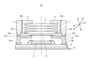
- FIG. 1 is a cross-sectional view showing a lens module that is an example of a connection structure according to the present technology.
- FIG. 2 is a cross-sectional view for explaining an example of step A of the manufacturing method of the lens module.
- FIG. 3 is a cross-sectional view for explaining an example of step B of the manufacturing method of the lens module.
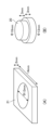
- 4A and 4B show members used when measuring the adhesive strength of the cured photocurable adhesive composition, where FIG. 4A is a perspective view of an LCP and FIG. 4B is a perspective view of a PC.
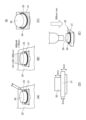
- FIG. 5 is a perspective view illustrating a method for measuring the adhesive strength of the cured photocurable adhesive composition.
- FIG. 1 is a cross-sectional view showing a lens module that is an example of a connection structure according to the present technology.
- FIG. 2 is a cross-sectional view for explaining an example of step A of the manufacturing method of the lens module.
- FIG. 3 is a cross-sectional view for explaining an example of step
- FIG. 5(A) is a perspective view illustrating an example of a method for placing a PC and an LCP on a jig and applying a photocurable adhesive composition between the PC and the LCP.
- FIG. 5(B) is a perspective view illustrating an example of a method for irradiating the photocurable adhesive composition with UV.
- FIG. 5(C) is a perspective view illustrating an example of a connection structure in which a PC and an LCP are connected with a cured product of the photocurable adhesive composition.
- FIG. 5(D) is a side view illustrating an example of a connection structure in which a PC and an LCP are connected with a cured product of the photocurable adhesive composition.
- FIG. 5(E) is a perspective view illustrating a method for measuring the adhesive strength of the cured product of the photocurable adhesive composition in the connection structure.
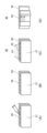
- FIG. 6 is a perspective view illustrating a method for evaluating the curability of a photocurable adhesive composition
- FIGS. 6(A) and 6(B) are perspective views illustrating an example of a method for filling a gap between LCPs with a photocurable adhesive composition
- FIG. 6(C) is a perspective view illustrating an example of a method for curing the photocurable adhesive composition
- FIG. 6(D) is a perspective view illustrating a method for measuring the length of the cured portion of the cured product in the UV irradiation direction in a connection structure connected with a cured product of the photocurable adhesive composition.
- FIG. 7 is a perspective view illustrating a method for evaluating the light-blocking properties of a cured photocurable adhesive composition.
- FIGS. 7(A) and (B) are perspective views illustrating a method for applying a photocurable adhesive composition onto one piece of glass, placing the other piece of glass on the applied photocurable adhesive composition, and crushing the photocurable adhesive composition with the thickness of a spacer.
- FIG. 7(C) is a perspective view illustrating a method for curing the photocurable adhesive composition to obtain a connection structure in which two pieces of glass are connected by a cured product of the photocurable adhesive composition.
- the photocurable adhesive composition according to the present technology comprises (a) a photocurable radical polymerization component (hereinafter also referred to as “component (a)”) and (b) a photoradical generator (hereinafter also referred to as “component (b)”). “), (c) a photoacid generator (hereinafter also referred to as “component (c)”), (d) a leuco dye (hereinafter also referred to as “component (d)”), and (e) an onium and a thermal acid generator having a salt structure (hereinafter also referred to as “component (e)”).
- component (a) a photocurable radical polymerization component
- component (b) a photoradical generator
- component (c) a photoacid generator
- component (d) a leuco dye
- component (e) an onium and a thermal acid generator having a salt structure
- the photocurable adhesive composition consisting of components (a) to (d) undergoes a curing reaction of the photocurable radical polymerization component when irradiated with light, and also undergoes a reaction in which an acid is generated from the photoacid generator when irradiated with light. The generated acid is added to the leuco dye, causing a reaction that changes the photocurable adhesive composition from colorless to colored, thereby imparting light-blocking properties.
- the photocurable adhesive composition according to the present technology undergoes a curing reaction and a light-blocking reaction when irradiated with light.
- the photocurable adhesive composition consisting of components (a) to (d) fades in a high-temperature, high-humidity environment after curing, and therefore loses its light-blocking properties over time.
- the photocurable adhesive composition according to the present technology further contains (e) a thermal acid generator having an onium salt structure in addition to the components (a) to (d).
- a thermal acid generator having an onium salt structure in addition to the components (a) to (d).
- a high temperature and high humidity environment refers to an environment with a temperature and humidity that causes fading of the leuco dye in the cured product of the photocurable adhesive composition, for example, 85°C and a relative humidity of 85%.
- the photocurable adhesive composition according to the present technology has good light-shielding properties after curing. That is, the cured product of the photocurable adhesive composition according to the present technology also has good light-shielding properties before being placed in a high-temperature, high-humidity environment. Furthermore, the photocurable adhesive composition according to the present technology has good curability and adhesive strength after curing. Therefore, the photocurable adhesive composition according to the present technology can be preferably applied to a connection structure in which a first member and a second member are connected via a cured product of the photocurable adhesive composition according to the present technology.
- the initial adhesive strength required for the lens module can be improved, and the adhesive strength can be maintained after being placed in a high-temperature, high-humidity environment.
- the photocurable adhesive composition according to the present technology has good curing properties even when irradiated only with light of a single wavelength (e.g., ultraviolet light with a wavelength of 365 nm), and also has good light-shielding properties after curing.
- a single wavelength e.g., ultraviolet light with a wavelength of 365 nm
- the photocurable radical polymerization component is a compound containing a radical polymerizable group.
- the component (a) is preferably a compound containing a (meth)acryloyl group.
- the (meth)acryloyl group includes both a methacryloyl group and an acryloyl group.
- the component (a) may be a monomer, an oligomer, or a combination of a monomer and an oligomer, but from the viewpoint of improving the adhesive strength of the photocurable adhesive composition after curing and improving the curability of the photocurable adhesive composition, a combination of an oligomer (photocurable oligomer) and a monomer (photocurable monomer) is preferred.
- the photocurable oligomer (hereinafter also referred to as "(a1) component”) may be monofunctional, bifunctional, or polyfunctional, but from the viewpoint of improving the adhesive strength of the photocurable adhesive composition after curing and from the viewpoint of improving the curability of the photocurable adhesive composition, a bifunctional photocurable oligomer or a polyfunctional photocurable oligomer is preferred.
- a urethane (meth)acrylate oligomer for example, a urethane (meth)acrylate oligomer can be used, and specifically, a urethane (meth)acrylate oligomer having a polybutadiene skeleton, a urethane (meth)acrylate oligomer having a polycarbonate skeleton, a urethane (meth)acrylate oligomer having a polyether skeleton, a urethane (meth)acrylate oligomer having a polyester skeleton, an isoprene-based (meth)acrylate oligomer, etc. can be used.
- a urethane (meth)acrylate having a polyester skeleton is preferred.
- a commercially available photocurable oligomer for example, UV-3200B (manufactured by Mitsubishi Chemical Corporation) can be used.
- the photocurable oligomer may be used alone or in combination of two or more kinds.
- the photocurable monomer (hereinafter also referred to as "(a2) component”) may be monofunctional, bifunctional, or polyfunctional.
- a monofunctional monomer having a ring structure specifically, an alicyclic structure, a heterocyclic structure, an aromatic ring structure, etc.
- the (a2) component may be used alone or in combination of two or more.
- the (a2) photocurable monomer preferably contains an acrylamide monomer from the viewpoint of improving the light-shielding property of the photocurable adhesive composition, improving the adhesive strength of the photocurable adhesive composition after curing, and improving the curability of the photocurable adhesive composition. It is also preferable to use an acrylamide monomer in combination with a monomer having an aromatic ring structure, or to use an acrylamide monomer in combination with a monomer having an alicyclic structure.
- Acrylamide monomers include (meth)acrylamide, dimethyl (meth)acrylamide, diethyl (meth)acrylamide, (meth)acryloylmorpholine, hydroxyethyl (meth)acrylamide, isopropyl (meth)acrylamide, dimethylaminopropyl (meth)acrylamide, (meth)acrylamide, N-t-butyl (meth)acrylamide, N-methylol (meth)acrylamide, N-methoxymethyl (meth)acrylamide, N-butoxymethyl (meth)acrylamide, and diacetone (meth)acrylamide.
- Examples of monomers having an aromatic ring structure include benzyl (meth)acrylate, phenyl (meth)acrylate, phenoxyethyl (meth)acrylate, phenoxypolyethylene glycol (meth)acrylate, nonylphenoxypolyethylene glycol (meth)acrylate, phenoxypolypropylene glycol (meth)acrylate, 2-(meth)acryloyloxyethyl-2-hydroxypropyl phthalate, and 2-hydroxy-3-phenoxypropyl (meth)acrylate.
- Examples of monomers having an alicyclic structure include isobornyl (meth)acrylate, dicyclopentanyl (meth)acrylate, dicyclopentenyl (meth)acrylate, dicyclopentenyloxy (meth)acrylate, dicyclopentenyloxyethyl acrylate, adamantyl (meth)acrylate, 2-alkyl-2-adamantyl (meth)acrylate, 3-hydroxy-1-adamantyl (meth)acrylate, and 1-perfluoroadamantyl (meth)acrylate.
- component (a2) contains acryloyl morpholine, and it is also preferable to use acryloyl morpholine in combination with isobornyl acrylate, or acryloyl morpholine in combination with benzyl acrylate.
- the total content of component (a) in the photocurable adhesive composition is preferably 90% by mass or more from the viewpoint of improving the adhesive strength of the cured photocurable adhesive composition and improving the curability of the photocurable adhesive composition.
- the upper limit of the total content of component (a) in the photocurable adhesive composition is not particularly limited, and may be, for example, 96% by mass or less, or 94% by mass or less.
- the content of the (a1) component relative to the total amount of the (a) component is preferably 10% by mass or more, may be 15% by mass or more, may be 20% by mass or more, may be 10 to 60% by mass, may be 10 to 50% by mass, may be 10 to 40% by mass, or may be 40 to 60% by mass.
- the content of the (a2) component relative to the total amount of the (a) component is preferably 20% by mass or more, may be 30% by mass or more, may be 40% by mass or more, may be 50% by mass or more, may be 60% by mass or more, may be 40 to 95% by mass, may be 20 to 80% by mass, may be 40 to 80% by mass, may be 40 to 75% by mass, or may be 40 to 70% by mass.
- the total amount thereof satisfies the above range.
- the content of the (a1) component relative to the total amount of the photocurable adhesive composition is preferably 9 to 71 mass%, may be 9 to 54 mass%, may be 9 to 45 mass%, may be 35 to 54 mass%, or may be 35 to 45 mass%.
- the content of the (a2) component relative to the total amount of the photocurable adhesive composition is preferably 18 to 91 mass%, may be 36 to 91 mass%, may be 36 to 80 mass%, or may be 50 to 91 mass%.
- the photoradical generator is a photopolymerization initiator that generates radicals by irradiation with light.
- the component (b) is preferably, for example, an alkylphenone-based photopolymerization initiator or an acylphosphine oxide-based photopolymerization initiator.
- Specific examples of the component (b) include 1-hydroxycyclohexyl phenyl ketone and phenylbis(2,4,6-trimethylbenzoyl)phosphine oxide.
- the component (b) Commercially available products of the component (b) include, for example, PI-184 (manufactured by Aal Chem) and Omnirad 819 (manufactured by IGM resins B.V.).
- the component (b) may be used alone or in combination of two or more types.
- the content of the (b) component may be 0.1 parts by mass or more, or may be 0.5 parts by mass or more, or may be 1 part by mass or more, when the total amount of the (a) component is 100 parts by mass, from the viewpoint of improving the adhesive strength of the cured photocurable adhesive composition and the curability of the photocurable adhesive composition.
- the upper limit of the content of the (b) component may be 15 parts by mass or less, or may be 10 parts by mass or less, or may be 5 parts by mass or less, when the total amount of the (a) component is 100 parts by mass, from the viewpoint of improving the adhesive strength of the cured photocurable adhesive composition and the curability of the photocurable adhesive composition.
- the photoacid generator is a compound that generates an acid such as a Lewis acid or a Bronsted acid upon irradiation with light.
- the acid generated from the component (c) is added to the leuco dye, thereby changing the photocurable adhesive composition from colorless to colored, and thus imparting light-shielding properties to the photocurable adhesive composition.
- the component (c) does not absorb too much light at a wavelength of 365 nm, and for example, an iodonium salt-based photoacid generator or a sulfonium salt-based photoacid generator is preferable.
- the component (c) contains, as a counter anion, a hexafluorophosphate anion ([PF 6 ] - ), an anion represented by [PR 1 6 ] - or an anion represented by [BR 2 4 ] - .
- each R 1 independently represents a fluorine atom or a fluorinated alkyl group, and at least one R 1 is a fluorinated alkyl group.
- An example of the anion represented by [PR 1 6 ] - is [PF 3 (C 2 F 5 ) 3 ] - .
- each R 2 independently represents a fluorine atom or a fluorinated alkyl group having 1 to 4 carbon atoms, and at least one R 2 is a fluorinated alkyl group.
- An example of the anion represented by [BR 2 4 ] - is tetrakis(hexafluorophenyl)borate anion.
- component (c) examples include an iodonium salt-based photoacid generator containing a hexafluorophosphate anion, a sulfonium salt-based photoacid generator containing a hexafluorophosphate anion, a sulfonium salt-based photoacid generator containing [ PF3 ( C2F5 ) 3 ] - , a sulfonium salt-based photoacid generator containing a tetrakis(hexafluorophenyl)borate anion, and an iodonium salt-based photoacid generator containing a tetrakis(hexafluorophenyl)borate anion.
- iodonium salt-based photoacid generators containing tetrakis(hexafluorophenyl)borate anion iodonium salt-based photoacid generators containing tetrakis(hexafluorophenyl)borate anion
- iodonium salt-based photoacid generators containing hexafluorophosphate anion iodonium salt-based photoacid generators containing hexafluorophosphate anion
- sulfonium salt-based photoacid generators containing hexafluorophosphate anion sulfonium salt-based photoacid generators containing tetrakis(hexafluorophenyl)borate anion, which have relatively small light absorption at a wavelength of 365 nm
- iodonium salt-based photoacid generators containing tetrakis(hexafluorophenyl)borate anion iodonium salt
- component (c) Commercially available products of component (c) include PI-2074 (manufactured by Arkema), WPI-170 (manufactured by Fujifilm Wako Pure Chemical Industries, Ltd.), AT-6992 (manufactured by Tomoe Engineering Co., Ltd.), CPI-310B (manufactured by San-Apro Ltd.), and CPI-410S (manufactured by San-Apro Ltd.).
- Component (c) may be used alone or in combination of two or more types.
- the content of the (c) component may be 0.1 parts by mass or more, 0.5 parts by mass or more, or 1 part by mass or more, when the total amount of the (a) component is 100 parts by mass, from the viewpoint of improving the light-shielding properties of the cured photocurable adhesive composition.
- the upper limit of the content of the (c) component may be 20 parts by mass or less, 10 parts by mass or less, 5 parts by mass or less, or 3 parts by mass or less, when the total amount of the (d) component is 100 parts by mass, from the viewpoint of curability.
- the content of the (c) component is preferably in the range of 0.5 to 6 parts by mass, when the total amount of the (a) component is 100 parts by mass, from the viewpoint of improving the light-shielding properties of the cured photocurable adhesive composition and the curability of the photocurable adhesive composition.
- the content of the (c) component may be in the range of 100 to 600 parts by mass, when the total amount of the (d) component is 100 parts by mass, from the viewpoint of improving the curability of the photocurable adhesive composition.
- two or more (c) components are used in combination, it is preferable that the total amount falls within the above range.
- the leuco dye is a compound that develops color upon contact with an acid, and is a component for imparting light-shielding properties to the cured product of the photocurable adhesive composition.
- the component (d) is preferably a leuco dye, and more preferably a leuco dye that can develop a black color.
- a specific example of the component (d) is (2'-anilino-6'-dibutylamino-3'-methylspiro[phthalide-3,9'-[9H]xanthene]).
- a commercially available product of the component (d) is BLACK 400 (manufactured by Yamada Chemical Co., Ltd.).
- the component (d) may be used alone or in combination of two or more types.
- the photocurable adhesive composition according to the present technology when BLACK 400 represented by the following formula 1 is used as component (d), after curing, the photocurable adhesive composition according to the present technology generates an acid from component (e) in a high-temperature, high-humidity environment.
- the generated acid is supplied to component (d)
- the lactone ring in component (d) opens as shown in formula 2, and component (d) changes from colorless to colored (black) and develops color. This imparts light-blocking properties to the photocurable adhesive composition, thereby suppressing fading of component (d) in a high-temperature, high-humidity environment.
- the content of component (d) in the photocurable adhesive composition is preferably 0.2 mass% or more, and may be 0.5 mass% or more, 0.8 mass% or more, or 1 mass% or more.
- the upper limit of the content of component (d) in the photocurable adhesive composition is not particularly limited, and may be, for example, 5 mass% or less, 3 mass% or less, 2 mass% or less, or 1.5 mass% or less. When two or more types of components (d) are used in combination, it is preferable that the total amount satisfies the above range.
- the thermal acid generator is a compound that generates an acid under a high-temperature and high-humidity environment and suppresses discoloration of the (d) component in the cured product of the photocurable adhesive composition.
- the (e) component is preferably a thermal acid generator having an onium salt structure, and more preferably a thermal acid generator having a quaternary ammonium salt structure or a thermal acid generator having a sulfonium salt structure.
- the (e) component preferably contains tetrakis(hexafluorophenyl)borate anion or CF 3 SO 3 - as a counter anion.
- Specific examples of the (e) component include a photoacid generator containing a tetrakis(hexafluorophenyl)borate anion and a quaternary ammonium salt structure, and a photoacid generator containing CF 3 SO 3 - and a quaternary ammonium salt structure.
- component (e) Commercially available products of the component (e) include CXC-1821 and CXC-1614 (both manufactured by Kusumoto Chemical Industries, Ltd.) and TA-100 (manufactured by San-Apro Co., Ltd.)
- the component (e) may be used alone or in combination of two or more types.
- the content of the (e) component is preferably 0.1 mass% or more, and may be 0.5 mass% or more, or may be 0.75 mass% or more, based on the total content of the (d) component.
- the upper limit of the content of the (e) component is not particularly limited, and may be, for example, 3 mass% or less, 2 mass% or less, or 1.5 mass% or less, based on the total content of the (d) component. When two or more types of (e) components are used in combination, it is preferable that the total amount satisfies the above range.
- the photocurable adhesive composition may further contain other components in addition to the components (a) to (e) as long as the effects of the present technology are not impaired.
- the other components include an acid trapping agent, a filler, a solvent, a sensitizer, etc.
- the photocurable adhesive composition is substantially free of a sensitizer, and the content of the sensitizer in the photocurable adhesive composition is more preferably 0.5 mass% or less, even more preferably 0.4 mass% or less, and particularly preferably 0.1 mass% or less.
- the irradiated light is not absorbed by the sensitizer, and deterioration of the curability of the photocurable adhesive composition can be prevented.
- the cured product of the photocurable adhesive composition according to the present technology is a product of curing the photocurable adhesive composition containing the above-mentioned components (a) to (e).
- the cured product of the photocurable adhesive composition according to the present technology will also be simply referred to as the "cured product according to the present technology".
- acid is generated from component (e) in a high-temperature, high-humidity environment, and the generated acid is supplied to component (d), thereby suppressing discoloration of component (d) in a high-temperature, high-humidity environment.
- the cured product according to the present technology can maintain light-shielding properties even in a high-temperature, high-humidity environment.
- the cured product according to the present technology has good light-shielding properties before and after being placed in a high-temperature, high-humidity environment.
- the cured product according to the present technology preferably has a transmittance of 25% or less at a wavelength of 550 nm when the product has a thickness of 200 ⁇ m, and more preferably has a transmittance of less than 10% at a wavelength of 550 nm, before being placed in a high-temperature, high-humidity environment.
- the cured product according to the present technology has a transmittance of 25% or less at a wavelength of 550 nm, thereby achieving good light-blocking properties.
- the increase in transmittance of the cured product according to the present technology at a wavelength of 550 nm after being placed in a high-temperature, high-humidity environment (for example, an environment of 85° C. and relative humidity of 85%) for 72 hours is 5% or less compared to the initial transmittance (before being placed in the high-temperature, high-humidity environment).
- the transmittance of the cured product according to the present technology can be measured by the method described in the Examples below.
- the cured product of this technology has good adhesive strength and can maintain good adhesive strength even after being placed in a high-temperature, high-humidity environment.
- the cured product of this technology has good adhesive strength before and after being placed in a high-temperature, high-humidity environment.
- the adhesive strength of the cured product of this technology can be measured by the method described in the Examples below.
- FIG. 1 is a cross-sectional view showing a lens module 1, which is an example of the connection structure according to the present technology.
- the lens module 1 includes, for example, a flexible substrate 2 (FPC: Flexible Printed Circuits), a circuit board 3, an image sensor 4, a lens 5, a lens barrel 6, a housing 7, a sensor frame 8, and an IR cut filter 9.
- FPC Flexible Printed Circuits
- the focal length between the lens 5 and the image sensor 4 arranged on the circuit board 3 is fixed by the cured products 14d and 14e of the adhesive.
- the lens 5, the lens barrel 6, and the housing 7 are also collectively referred to as an optical unit 11.
- the flexible substrate 2, the circuit board 3, and the image sensor 4 are also collectively referred to as a sensor unit 12.
- the lens barrel 6 and the housing 7 are also collectively referred to as a lens housing 13.
- Examples of the first and second members constituting the connection structure of the present technology include the circuit board 3, lens barrel 6, housing 7, and sensor frame 8 in the lens module 1 shown in FIG. 1.
- the flexible substrate 2 may be, for example, a glass substrate or a plastic substrate.
- the flexible substrate 2 has terminals for connecting to the circuit substrate 3.
- the flexible substrate 2 may have a single-layer structure or a multi-layer structure.
- the circuit board 3 is a board on which the image sensor 4, sensor frame 8, etc. are mounted. Wiring for transmitting signals from the image sensor 4, etc. is arranged on the circuit board 3.
- the circuit board 3 is formed, for example, from a printed circuit board (PCB).
- the circuit board 3 has terminals for connecting to the flexible board 2, and is connected to the terminals of the flexible board 2 via a cured product of the photocurable adhesive composition.
- the image sensor 4 receives the light focused by the lens and converts it into an electrical signal.
- the image sensor 4 is composed of, for example, a charge coupled device (CCD) or a complementary metal oxide semiconductor (CMOS).
- CMOS complementary metal oxide semiconductor
- the image sensor 4 is disposed on the circuit board 3.
- the image sensor 4 is connected to a pad formed on the circuit board 3 by, for example, a bonding wire. This pad is connected to the wiring of the circuit board 3.
- Lens 5 is for collecting light from a subject.
- Lens 5 is attached to lens barrel 6 at a predetermined position to converge light (image) on the light receiving surface of image sensor 4.
- Lens 5 has a plurality of optical elements arranged along lens barrel 6. For example, as shown in FIG. 1, lens 5 is fixed to lens barrel 6 by a cured product 14a of a photocurable adhesive composition.
- Lens 5 can be made of, for example, glass, plastic, etc.
- the lens barrel 6 is a lens tube for holding the lens 5, and is configured, for example, in a cylindrical shape.
- the lens barrel 6 is fixed to the housing 7 by a cured product 14b of the photocurable adhesive composition.
- the material of the lens barrel 6 may be, for example, an engineering plastic such as LCP (liquid crystal polymer) or polycarbonate.
- the housing 7 is a case for holding the lens barrel 6. From the viewpoint of moldability, examples of the material of the housing 7 include engineering plastics such as LCP (liquid crystal polymer) and polycarbonate.
- the housing 7 is fixed to the lens barrel 6 by the cured product 14b of the photocurable adhesive composition, and is fixed to the sensor frame 8 by the cured product 14d of the photocurable adhesive composition.
- the sensor frame 8 is fixed to the housing 7 by the cured product of the photocurable adhesive composition 14d, and is fixed to the circuit board 3 by the cured product of the photocurable adhesive composition 14e.
- the IR cut filter 9 is a filter that transmits visible light contained in the light that has passed through the lens 5 and cuts infrared light.
- the IR cut filter 9 is disposed between the sensor frame 8 and the lens 5.
- the IR cut filter 9 is fixed to the sensor frame 8 by the cured product 14c of the photocurable adhesive composition.
- All of the cured products 14a to 14e of the photocurable adhesive composition shown in FIG. 1 may be the cured products according to the present technology described above, or at least one of the cured products 14a to 14e of the photocurable adhesive composition may be the cured product according to the present technology.
- the cured product according to the present technology may be preferably used as the cured product 14b of the photocurable adhesive composition in the lens module 1 shown in FIG. 1.
- an example of a connection structure according to the present technology is a lens module 1 in which a housing 7 as a first member and a lens barrel 6 as a second member are connected via a cured product 14b of the photocurable adhesive composition as a cured product according to the present technology.
- connection structure according to the present technology the first member and the second member are connected via the cured product according to the present technology, so that the cured product can maintain its light-shielding properties even when placed in a high-temperature and high-humidity environment.
- first member and the second member are connected via the cured product according to the present technology, so that the adhesive strength is good and can maintain good adhesive strength even when placed in a high-temperature and high-humidity environment.
- the method for manufacturing a connection structure according to the present technology includes a step of irradiating a photocurable adhesive composition disposed between a first member and a second member with light to cure the photocurable adhesive composition.
- the first member and the second member are synonymous with the first member and the second member in the connection structure described above.
- the light irradiation conditions can be appropriately selected depending on the application of the photocurable adhesive composition according to the present technology.
- a UV-LED with a wavelength of 365 nm can be used as the light source, and the conditions can be an illuminance of 300 to 800 mW/cm 2 and an irradiation time of 3 to 20 seconds.
- step A involves applying a photocurable adhesive composition between the circuit board 3 on which the image sensor 4 is mounted and the sensor frame 8, and/or between the sensor frame 8 and the optical unit 11 including the lens 5 and the lens housing 13.
- step A includes at least one of applying a photocurable adhesive composition 10e to the surface of the circuit board 3 on which the image sensor 4 is mounted, and applying a photocurable adhesive composition 10d to the surface of the sensor frame 8 arranged on the circuit board 3 on which the image sensor 4 is mounted.
- the photocurable adhesive composition 10d may be applied in step A. If the circuit board 3 on which the image sensor 4 is mounted and the sensor frame 8 are not fixed in advance, both the photocurable adhesive compositions 10d and 10e may be applied in step A. If the sensor frame 8 and the optical unit 11 are fixed in advance, only the photocurable adhesive composition 10e may be applied in step A. If the lens barrel 6 and the housing 7 are not fixed in advance, the photocurable adhesive composition 10b may also be applied in step A. In this way, all of the photocurable adhesive compositions 10a to 10e shown in FIG. 2 may be the photocurable adhesive composition according to the present technology described above, or at least one of the photocurable adhesive compositions 10a to 10e may be the photocurable adhesive composition according to the present technology.
- the method for applying the photocurable adhesive compositions 10a to 10e is not particularly limited, and examples include roll coating, doctor knife, die coating, dip coating, bar coating, inkjet, and jet dispensing.
- FIG. 3 is a cross-sectional view for explaining an example of step B of the manufacturing method of a lens module.
- a connection structure 15 is formed, which includes a circuit board 3 on which an image sensor 8 is mounted, a sensor frame 8, and an optical unit 11, and in which the lens 5 and image sensor 4 are focused.
- the optical unit 11 is placed on a photocurable adhesive composition 10d, and a connection structure 15 is formed in which the lens 5 constituting the optical unit 11 and the image sensor 4 are focused. In this way, in step B, the lens 5 and image sensor 4 are aligned.
- step B the optical axis of the optical unit 11 is adjusted.
- the adjustment of the optical axis of the optical axis unit 11 can be performed by displacing the optical unit 11, for example, using an active alignment method.
- the adjustment of the optical axis of the optical unit 11 includes, for example, adjustment in the x-, y-, and z-axes, and adjustment of the rotation angle.
- step C the photocurable adhesive compositions 10a to 10e in the connection structure 15 are irradiated with light to cure the photocurable adhesive compositions 10a to 10e.
- the connection structure 15 formed in step B is fixed in the correct position, i.e., with the lens 5 and image sensor 4 in focus. This manufacturing method results in the lens module 1 shown in FIG. 1.
- UV-3200B urethane acrylate oligomer, manufactured by Mitsubishi Chemical Corporation IBXA: isobornyl acrylate, manufactured by Osaka Organic Chemical Industry Co., Ltd. #160: benzyl acrylate, manufactured by Osaka Organic Chemical Industry Co., Ltd.
- ACMO acryloyl morpholine, manufactured by KJ Chemicals Co., Ltd.
- PI-2074 Iodonium salt/tetrakis(hexafluorophenyl)borate anion, manufactured by Arkema WPI-170: Iodonium salt/[PF 6 ] - , manufactured by Fujifilm Wako Pure Chemical Industries, Ltd. AT-6992: Sulfonium salt/[PF 6 ] - , manufactured by Tomoe Engineering Co., Ltd.
- CPI-310B Sulfonium salt/tetrakis(hexafluorophenyl)borate anion, manufactured by San-Apro Co., Ltd.
- CPI-410S Sulfonium salt/[PF 3 (C 2 F 5 ) 3 ] - , manufactured by San-Apro Co., Ltd.
- CXC-1821 quaternary ammonium salt/tetrakis(hexafluorophenyl)borate anion, manufactured by Kusumoto Chemical Industries, Ltd.
- CXC-1614 quaternary ammonium salt/CF 3 SO 3 ⁇ , manufactured by Kusumoto Chemical Industries, Ltd.
- NACURE 2500 amine salt/tosylic acid, manufactured by Kusumoto Chemical Industries, Ltd.
- NACURE 5225 amine salt/DDBSA (dodecylbenzenesulfonic acid), manufactured by Kusumoto Chemical Industries, Ltd.
- TA-100 sulfonium salt/[PF 3 (C 2 F 5 ) 3 ] ⁇ , manufactured by San-Apro Ltd.
- the photocurable adhesive compositions of Experimental Examples 1 to 28 were prepared by uniformly mixing the components shown in Table 1 in the blending ratios (parts by mass) shown in Table 1.
- the photocurable adhesive composition of Experimental Example 2 which did not contain a thermal acid generator
- the photocurable adhesive composition of Experimental Example 24, which did not contain a leuco dye are comparative examples.
- FIG. 4 shows members used in measuring the adhesive strength of the cured photocurable adhesive composition
- FIG. 4(A) is a perspective view of an LCP 21
- FIG. 4(B) is a perspective view of a PC 20 (Panlite L-1225Y, manufactured by Teijin).
- FIG. 5 is a perspective view for explaining a method for measuring the adhesive strength of the cured photocurable adhesive composition.
- the PC 20 and the LCP 21, the surface of which was plasma-treated were placed on a jig 22, and the photocurable adhesive composition 23 of Experimental Examples 1 to 28 was applied between the PC 20 and the LCP 21.
- Fig. 5(B) the photocurable adhesive composition 23 was irradiated with UV using a UV-LED (wavelength 365 nm) at an illuminance of 800 mW/ cm2 for 20 seconds to cure the photocurable adhesive composition 23, thereby obtaining a connection structure 25 (see Figs. 5(C) and (D)) in which the PC 20 and the LCP 21 were connected by a cured product 24 of the photocurable adhesive composition.
- Fig. 5(C) is a perspective view showing an example of the connection structure 25
- Fig. 5(D) is a side view showing an example of the connection structure 25.
- FIG. 5(E) is a perspective view for explaining a method for measuring the adhesive strength of the cured product 24 of the photocurable adhesive composition in the connection structure 25.
- a measuring device Japan Measurement Systems, load tester: JSV H1000
- JSV H1000 load tester
- Five test pieces (connection structures 25) were measured, and the average value was taken as the push strength (adhesive strength). The results are shown in Table 1.
- Push strengths of over 4.5 MPa were evaluated as ⁇ , those of 0.5 MPa to 4.5 MPa were evaluated as ⁇ , and those of less than 0.5 MPa were evaluated as ⁇ . For practical purposes, push strengths of 0.5 MPa or more are preferable, and those of over 4.5 MPa are more preferable.
- connection structure 25 shown in Figs. 5(C) and (D) was placed in an environment of 85 ° C. and 85% relative humidity for 72 hours, and then, as shown in Fig. 5(E), the connection structure 25 was pushed from the PC 20 side in compression mode at 200 ⁇ m/sec using a measuring device (Japan Measurement Systems Co., Ltd., load tester: JSV H1000) until the connection structure was removed, and the maximum value (peak strength) at that time was measured. Five test pieces (connection structures 25) were measured, and the average value was taken as the value of push strength (adhesive strength). The results are shown in Table 1.
- the push strength after HTHH was more than 4.5 MPa, it was evaluated as ⁇ , when it was 0.5 MPa or more and 4.5 MPa or less, it was evaluated as ⁇ , and when it was less than 0.5 MPa, it was evaluated as ⁇ .
- the push strength after HTHH is preferably 0.5 MPa or more, and more preferably more than 4.5 MPa.
- ⁇ Curability> 6 is a perspective view for explaining a method for evaluating the curability of a photocurable adhesive composition.
- two LCPs 26 and 27 (LAPEROS E525T, manufactured by Polyplastics Co., Ltd., flat plate: 20 mm ⁇ 50 mm ⁇ 2 mmt) were arranged so that the gap between them was 50 ⁇ m, and as shown in FIG. 6(B), the photocurable adhesive composition 28 of Experimental Examples 1 to 28 was filled between the LCPs 26 and 27.
- FIG. 6(A) two LCPs 26 and 27 (LAPEROS E525T, manufactured by Polyplastics Co., Ltd., flat plate: 20 mm ⁇ 50 mm ⁇ 2 mmt) were arranged so that the gap between them was 50 ⁇ m
- FIG. 6(B) the photocurable adhesive composition 28 of Experimental Examples 1 to 28 was filled between the LCPs 26 and 27.
- FIG. 6(A) two LCPs 26 and 27 (LAPEROS E525T, manufactured by Polyplastics Co.
- a UV-LED (wavelength 365 nm) was used to irradiate the photocurable adhesive composition 28 with UV light at an illuminance of 300 mW/cm 2 for 3 seconds in the filling direction (perpendicular direction) of the photocurable adhesive composition 28, curing the photocurable adhesive composition 28, and obtaining a connection structure 30 in which the two LCPs 26 and 27 were connected with a cured product 29 of the photocurable adhesive composition.
- the length L of the cured portion of the cured product 29 in the UV irradiation direction in the surface direction of the LCP 26, which is the direction of UV irradiation, was measured using an optical microscope (manufactured by Keyence Corporation). Specifically, the uncured portion of the cured product 29 was wiped with a rag or cotton swab, and the length L of the remaining cured portion was measured. The results are shown in Table 1. When the length of the cured portion of the cured product 29 was more than 0.9 mm, it was evaluated as ⁇ , when it was 0.45 mm or more and 0.9 mm or less, it was evaluated as ⁇ , and when it was less than 0.45 mm, it was evaluated as ⁇ . For practical purposes, it is preferable that the length of the cured portion of the cured product 29 is 0.45 mm or more, and more preferably more than 0.9 mm.
- ⁇ Light blocking properties> 7 is a perspective view for explaining a method for evaluating the light-shielding property of the photocurable adhesive composition after curing.
- the photocurable adhesive composition 33 of Experimental Examples 1 to 28 was applied onto one glass 31, the other glass 32 was placed on the applied photocurable adhesive composition 33, and the photocurable adhesive composition 33 was pressed down to the thickness (200 ⁇ m) of the spacer 34.
- FIG. 7(A) and (B) the photocurable adhesive composition 33 of Experimental Examples 1 to 28 was applied onto one glass 31, the other glass 32 was placed on the applied photocurable adhesive composition 33, and the photocurable adhesive composition 33 was pressed down to the thickness (200 ⁇ m) of the spacer 34.
- the photocurable adhesive composition 33 was irradiated with UV light at an illuminance of 1000 mW/cm 2 for 4 seconds using a UV-LED (wavelength 365 nm), and the photocurable adhesive composition 33 was cured, and a connection structure 36 was obtained in which the two pieces of glass 31 and 32 were connected by the cured product 35 of the photocurable adhesive composition.
- the transmittance (initial transmittance) at a wavelength of 550 nm was measured for the cured product 35 in the obtained connection structure 36.
- the measurement device used was a UH4150 (UV-Vis spectrophotometer, manufactured by Hitachi High-Tech Science Corporation). An integrating sphere was used for the measurement. The results are shown in Table 1.
- the transmittance of the cured product 35 at a wavelength of 550 nm was less than 15%, it was evaluated as ⁇ , when the transmittance was 15% or more and 25% or less, it was evaluated as ⁇ , and when the transmittance was more than 25%, it was evaluated as x.
- the transmittance of the cured product 35 at a wavelength of 550 nm is preferably 25% or less, and more preferably less than 15%.
- the photocurable adhesive compositions used in Experimental Examples 1, 3, 4, and 9 were found to have good light-blocking properties after curing because they contained a specified amount or more of (e) a thermal acid generator having an onium salt structure.
- Experimental Example 2 which used a photocurable adhesive composition that did not contain (e) a thermal acid generator having an onium salt structure, was found to have poor light-blocking properties after HTHH.
- Experimental Examples 5 to 8, which used a thermal acid generator that did not have an onium salt structure were found to have poor light-blocking properties after HTHH.
- a photocurable adhesive composition containing (a) a photocurable radical polymerization component, (b) a photoradical generator, (c) a photoacid generator, (d) a leuco dye, and (e) a thermal acid generator having an onium salt structure is capable of maintaining light blocking properties after curing even in a high-temperature, high-humidity environment, regardless of the presence or absence of an acid trapping agent, and has good adhesive strength and curability after curing.
- the results of Experimental Examples 12 to 16 showed that (a) a photocurable adhesive composition containing a predetermined amount of oligomer as a photocurable radical polymerization component has better adhesive strength and curability after curing. Specifically, the results of Experimental Examples 13 to 16 showed that (a) a photocurable adhesive composition containing 9 to 54 mass% of oligomer as a photocurable radical polymerization component has good curability. Furthermore, the results of Experimental Examples 14 and 15 showed that (a) a photocurable adhesive composition containing 35 to 45 mass% of oligomer as a photocurable radical polymerization component has better adhesive strength and curability after curing.
- the results of Experimental Examples 24 to 26 show that the cured product of the photocurable adhesive composition containing a predetermined amount or more of (d) leuco dye has better light-blocking properties. Specifically, from the viewpoint of light-blocking properties, it was found that a photocurable adhesive composition containing 0.2 mass% or more of (d) leuco dye is preferable, and a photocurable adhesive composition containing 0.9 mass% or more of (d) leuco dye is more preferable. On the other hand, the results of Experimental Example 24 show that the cured product of the photocurable adhesive composition not containing (d) leuco dye has poor light-blocking properties both before and after HTHH.
- a photocurable adhesive composition containing (a) a photocurable radical polymerization component, (b) a photoradical generator, (c) a photoacid generator, (d) a leuco dye, and (e) a thermal acid generator having an onium salt structure has better curability and adhesive strength after curing when irradiated with light of a single wavelength of 365 nm than when irradiated with light from a mercury-xenon lamp, when compared with light from a mercury-xenon lamp. This is thought to be because light irradiated from a mercury-xenon lamp contains light of various wavelengths, and therefore is less likely to cure deep into the photocurable adhesive composition than light of a single wavelength of 365 nm.
Landscapes
- Chemical & Material Sciences (AREA)
- Organic Chemistry (AREA)
- Health & Medical Sciences (AREA)
- Chemical Kinetics & Catalysis (AREA)
- Medicinal Chemistry (AREA)
- Polymers & Plastics (AREA)
- Adhesives Or Adhesive Processes (AREA)
- Polymerisation Methods In General (AREA)
Abstract
硬化後に、高温高湿環境下でも遮光性の維持が可能な光硬化型接着組成物の提供。 光硬化型接着組成物は、(a)光硬化性ラジカル重合成分と、(b)光ラジカル発生剤と、(c)光酸発生剤と、(d)ロイコ色素と、(e)熱酸発生剤とを含む。また、光硬化型接着組成物の硬化物は、(a)光硬化性ラジカル重合成分と、(b)光ラジカル発生剤と、(c)光酸発生剤と、(d)ロイコ色素と、(e)オニウム塩構造を有する熱酸発生剤とを含む光硬化型接着組成物が硬化したものである。接続構造体は、第1の部材と第2の部材とが、光硬化型接着組成物の硬化物を介して接続されたものである。
Description
本技術は、光硬化型接着組成物、硬化物、接続構造体及び接続構造体の製造方法に関する。本出願は、日本国において2023年6月7日に出願された日本特許出願番号特願2023-093886を基礎として優先権を主張するものであり、この出願は参照されることにより、本出願に援用される。
樹脂硬化物に遮光性を付与する際、代表的な手法としてカーボンブラックなどの顔料を添加し、予め着色させる方法が挙げられる。しかし、光硬化型接着組成物(紫外線硬化型樹脂組成物)の場合、予め樹脂組成物を着色させると、紫外線が顔料に吸収され、樹脂組成物の深部まで紫外線が十分に届かず、樹脂組成物の深部で未硬化が発生するおそれがある。
そこで、紫外線硬化型樹脂組成物に、ロイコ色素(例えばロイコ染料)と光酸発生剤を添加することで、紫外線照射前は無色であるが、紫外線照射により光酸発生剤から酸が発生し、発生した酸がロイコ色素に付加することで着色させる方法が挙げられる。この方法では、樹脂組成物の硬化と着色のタイミングをずらすことが、紫外線硬化性と遮光性を両立するために重要となる。
例えば、特許文献1には、ロイコ染料と、光酸発生剤と、ラジカル重合性化合物と、ラジカル開始剤とを含有する光硬化性樹脂組成物に対し、波長の異なる複数の活性エネルギー線を順次照射する工程を特徴とする光硬化性樹脂組成物の硬化方法が記載されている。具体的に、特許文献1に記載の方法では、光硬化性樹脂組成物に対し、始めに波長400nm以上の活性エネルギー線を照射して、光ラジカル発生剤からラジカルを発生させ、次いで、波長370nm以下の活性エネルギー線を照射してすることで、光酸発生剤から酸を発生させ、高い遮光性と厚膜硬化性を両立させている。
しかし、特許文献1に記載の光硬化性樹脂組成物の硬化物は、高温高湿環境下で退色してしまい、経時で遮光性が損なわれてしまう。すなわち、特許文献1に記載の光硬化性樹脂組成物は、硬化後に、高温高湿環境下で遮光性の維持が困難である。
本技術は、このような従来の実情に鑑みて提案されたものであり、硬化後に、高温高湿環境下でも遮光性の維持が可能な光硬化型接着組成物を提供する。
本技術に係る光硬化型接着組成物は、(a)光硬化性ラジカル重合成分と、(b)光ラジカル発生剤と、(c)光酸発生剤と、(d)ロイコ色素と、(e)オニウム塩構造を有する熱酸発生剤とを含む。
本技術に係る硬化物は、(a)光硬化性ラジカル重合成分と、(b)光ラジカル発生剤と、(c)光酸発生剤と、(d)ロイコ色素と、(e)オニウム塩構造を有する熱酸発生剤とを含む光硬化型接着組成物が硬化したものである。
本技術に係る接続構造体は、上述の光硬化型接着組成物の硬化物を介して接続されたものである。
本技術に係る接続構造体の製造方法は、第1の部材と第2の部材との間に配置された上述の光硬化型接着組成物に光照射を行い、光硬化型接着組成物を硬化させる工程を含む。
本技術は、硬化後に、高温高湿環境下でも遮光性の維持が可能な光硬化型接着組成物を提供できる。
<光硬化型接着組成物>
本技術に係る光硬化型接着組成物は、(a)光硬化性ラジカル重合成分(以下、「(a)成分」ともいう)と、(b)光ラジカル発生剤(以下、「(b)成分」ともいう)と、(c)光酸発生剤(以下、「(c)成分」ともいう)と、(d)ロイコ色素(以下、「(d)成分」ともいう)と、(e)オニウム塩構造を有する熱酸発生剤(以下、「(e)成分」ともいう)とを含む。
本技術に係る光硬化型接着組成物は、(a)光硬化性ラジカル重合成分(以下、「(a)成分」ともいう)と、(b)光ラジカル発生剤(以下、「(b)成分」ともいう)と、(c)光酸発生剤(以下、「(c)成分」ともいう)と、(d)ロイコ色素(以下、「(d)成分」ともいう)と、(e)オニウム塩構造を有する熱酸発生剤(以下、「(e)成分」ともいう)とを含む。
(a)~(d)成分とからなる光硬化型接着組成物は、光照射により光硬化性ラジカル重合成分の硬化反応を奏するとともに、光照射により光酸発生剤から酸が発生し、発生した酸がロイコ色素に付加することで、光硬化型接着組成物を無色から有色に変化させる反応を奏し、遮光性が付与される。このように、本技術に係る光硬化型接着組成物は、光照射により硬化反応と遮光反応を奏するものである。しかし、(a)~(d)成分からなる光硬化型接着組成物は、硬化後に、高温高湿環境下で退色してしまうため、経時で遮光性が損なわれてしまう。
そこで、本技術に係る光硬化型接着組成物は、(a)~(d)成分に加えて、(e)オニウム塩構造を有する熱酸発生剤をさらに含むことにより、硬化後に、高温高湿環境下で熱酸発生剤から酸が発生し、発生した酸がロイコ色素に供給されることで、高温高湿環境下でのロイコ色素の退色を抑制できる。したがって、本技術に係る光硬化型接着組成物は、硬化後に、高温高湿環境下でも遮光性の維持が可能である。
ここで、高温高湿環境下とは、光硬化型接着組成物の硬化物中のロイコ色素が退色してしまう程度の温度と湿度の環境下をいい、例えば、85℃、相対湿度85%をいう。
また、本技術に係る光硬化型接着組成物は、硬化後の光硬化型接着組成物の遮光性が良好である。すなわち、本技術に係る光硬化型接着組成物の硬化物は、高温高湿環境下に置く前の遮光性も良好である。さらに、本技術に係る光硬化型接着組成物は、硬化性や、硬化後の接着強度も良好である。したがって、本技術に係る光硬化型接着組成物は、例えば、第1の部材と第2の部材とが本技術に係る光硬化型接着組成物の硬化物を介して接続された接続構造体に好ましく適用できる。本技術に係る光硬化型接着組成物を、例えば、レンズモジュール(カメラモジュール)における部材を接続するために用いた場合、レンズモジュールに求められる初期の接着強度を良好にすることができ、高温高湿環境下に置いた後の接着強度を維持することもできる。
また、上述した特許文献1に記載の技術では、高い遮光性と厚膜硬化性の両立のために、波長の異なる複数の活性エネルギー線を順次照射する工程が必須の条件である。これに対して、本技術に係る光硬化型接着組成物は、単一波長の光(例えば、波長365nmの紫外線)の照射のみでも、硬化性が良好であり、硬化後の遮光性も良好である。
<(a)光硬化性ラジカル重合成分>
光硬化性ラジカル重合成分は、ラジカル重合性基を含む化合物である。(a)成分は、硬化後の接着強度を良好にする観点や、光硬化型接着組成物の硬化性を良好にする観点では、(メタ)アクリロイル基を含む化合物が好ましい。(メタ)アクリロイル基とは、メタクリロイル基とアクリロイル基の両者を包含する。(a)成分は、モノマーであってもよいし、オリゴマーであってもよいし、モノマーとオリゴマーとの併用であってもよいが、硬化後の光硬化型接着組成物の接着強度を良好にする観点や、光硬化型接着組成物の硬化性を良好にする観点では、オリゴマー(光硬化性オリゴマー)と、モノマー(光硬化性モノマー)との併用が好ましい。
光硬化性ラジカル重合成分は、ラジカル重合性基を含む化合物である。(a)成分は、硬化後の接着強度を良好にする観点や、光硬化型接着組成物の硬化性を良好にする観点では、(メタ)アクリロイル基を含む化合物が好ましい。(メタ)アクリロイル基とは、メタクリロイル基とアクリロイル基の両者を包含する。(a)成分は、モノマーであってもよいし、オリゴマーであってもよいし、モノマーとオリゴマーとの併用であってもよいが、硬化後の光硬化型接着組成物の接着強度を良好にする観点や、光硬化型接着組成物の硬化性を良好にする観点では、オリゴマー(光硬化性オリゴマー)と、モノマー(光硬化性モノマー)との併用が好ましい。
<(a1)光硬化性オリゴマー>
光硬化性オリゴマー(以下、「(a1)成分」ともいう)は、単官能であってもよいし、2官能であってもよいし、多官能であってもよいが、硬化後の光硬化型接着組成物の接着強度を良好にする観点や、光硬化型接着組成物の硬化性を良好にする観点では、2官能の光硬化性オリゴマーまたは多官能の光硬化性オリゴマーが好ましい。(a1)光硬化性オリゴマーとしては、例えば、ウレタン(メタ)アクリレートオリゴマーを用いることができ、具体的には、ポリブタジエン骨格を有するウレタン(メタ)アクリレートオリゴマー、ポリカーボネート骨格を有するウレタン(メタ)アクリレートオリゴマー、ポリエーテル骨格を有するウレタン(メタ)アクリレートオリゴマー、ポリエステル骨格を有するウレタン(メタ)アクリレートオリゴマー、イソプレン系(メタ)アクリレートオリゴマーなどを用いることができる。これらの中でも、硬化後の光硬化型接着組成物の接着強度や硬化性の観点では、ポリエステル骨格を有するウレタン(メタ)アクリレートが好ましい。光硬化性オリゴマーの市販品としては、例えば、UV-3200B(三菱ケミカル社製)を用いることができる。光硬化性オリゴマーは、1種単独で用いてもよいし、2種以上を併用してもよい。
光硬化性オリゴマー(以下、「(a1)成分」ともいう)は、単官能であってもよいし、2官能であってもよいし、多官能であってもよいが、硬化後の光硬化型接着組成物の接着強度を良好にする観点や、光硬化型接着組成物の硬化性を良好にする観点では、2官能の光硬化性オリゴマーまたは多官能の光硬化性オリゴマーが好ましい。(a1)光硬化性オリゴマーとしては、例えば、ウレタン(メタ)アクリレートオリゴマーを用いることができ、具体的には、ポリブタジエン骨格を有するウレタン(メタ)アクリレートオリゴマー、ポリカーボネート骨格を有するウレタン(メタ)アクリレートオリゴマー、ポリエーテル骨格を有するウレタン(メタ)アクリレートオリゴマー、ポリエステル骨格を有するウレタン(メタ)アクリレートオリゴマー、イソプレン系(メタ)アクリレートオリゴマーなどを用いることができる。これらの中でも、硬化後の光硬化型接着組成物の接着強度や硬化性の観点では、ポリエステル骨格を有するウレタン(メタ)アクリレートが好ましい。光硬化性オリゴマーの市販品としては、例えば、UV-3200B(三菱ケミカル社製)を用いることができる。光硬化性オリゴマーは、1種単独で用いてもよいし、2種以上を併用してもよい。
<(a2)光硬化性モノマー>
光硬化性モノマー(以下、「(a2)成分」ともいう)は、単官能であってもよいし、2官能であってもよいし、多官能であってもよいが、例えば、環構造(具体的には、脂環構造、ヘテロ環構造、芳香環構造など)を有する単官能モノマーを用いることができる。(a2)成分は、1種単独で用いてもよいし、2種以上を併用してもよい。(a2)光硬化性モノマーとしては、光硬化型接着組成物の遮光性を良好にする観点、硬化後の光硬化型接着組成物の接着強度を良好にする観点、光硬化型接着組成物の硬化性を良好にする観点では、アクリルアミド系のモノマーを含むことが好ましく、アクリルアミド系のモノマーと芳香環構造を有するモノマーとの併用、または、アクリルアミド系のモノマーと脂環構造を有するモノマーとの併用も好ましい。
光硬化性モノマー(以下、「(a2)成分」ともいう)は、単官能であってもよいし、2官能であってもよいし、多官能であってもよいが、例えば、環構造(具体的には、脂環構造、ヘテロ環構造、芳香環構造など)を有する単官能モノマーを用いることができる。(a2)成分は、1種単独で用いてもよいし、2種以上を併用してもよい。(a2)光硬化性モノマーとしては、光硬化型接着組成物の遮光性を良好にする観点、硬化後の光硬化型接着組成物の接着強度を良好にする観点、光硬化型接着組成物の硬化性を良好にする観点では、アクリルアミド系のモノマーを含むことが好ましく、アクリルアミド系のモノマーと芳香環構造を有するモノマーとの併用、または、アクリルアミド系のモノマーと脂環構造を有するモノマーとの併用も好ましい。
アクリルアミド系のモノマーとしては、(メタ)アクリルアミド、ジメチル(メタ)アクリルアミド、ジエチル(メタ)アクリルアミド、(メタ)アクリロイルモルフォリン、ヒドロキシエチル(メタ)アクリルアミド、イソプロピル(メタ)アクリルアミド、ジメチルアミノプロピル(メタ)アクリルアミド、(メタ)アクリルアミド、N-t-ブチル(メタ)アクリルアミド、N-メチロール(メタ)アクリルアミド、N-メトキシメチル(メタ)アクリルアミド、N-ブトキシメチル(メタ)アクリルアミド、ダイアセトン(メタ)アクリルアミドなどが挙げられる。
芳香環構造を有するモノマーとしては、ベンジル(メタ)アクリレート、フェニル(メタ)アクリレート、フェノキシエチル(メタ)アクリレート、フェノキシポリエチレングリコール(メタ)アクリレート、ノニルフェノキシポリエチレングリコール(メタ)アクリレート、フェノキシポリプロピレングリコール(メタ)アクリレート、2-(メタ)アクリロイルオキシエチル-2-ヒドロキシプロピルフタレート、2-ヒドロキシ-3-フェノキシプロピル(メタ)アクリレートなどが挙げられる。
脂環構造を有するモノマーとしては、イソボルニル(メタ)アクリレート、ジシクロペンタニル(メタ)アクリレート、ジシクロペンテニル(メタ)アクリレート、ジシクロペンテニルオキシ(メタ)アクリレート、ジシクロペンテニルオキシエチルアクリレート、アダマンチル(メタ)アクリレート、2-アルキル-2-アダマンチル(メタ)アクリレート、3-ヒドロキシ-1-アダマンチル(メタ)アクリレート、1-パーフルオロアダマンチル(メタ)アクリレートなどが挙げられる。
特に、(a2)成分としては、アクリロイルモルフォリンを含むことが好ましく、アクリロイルモルフォリンとイソボルニルアクリレートとの併用、または、アクリロイルモルフォリンとベンジルアクリレートとの併用も好ましい。
光硬化型接着組成物中の(a)成分の総含有量は、硬化後の光硬化型接着組成物の接着強度を良好にする観点や、光硬化型接着組成物の硬化性を良好にする観点では、90質量%以上であることが好ましい。光硬化型接着組成物中の(a)成分の総含有量の上限値は、特に限定されず、例えば、96質量%以下であってもよく、94質量%以下であってもよい。
(a)成分が、(a1)成分と(a2)成分とを含む場合、(a)成分の総量に対する(a1)成分の含有量は、10質量%以上であることが好ましく、15質量%以上であってもよく、20質量%以上であってもよく、10~60質量%であってもよく、10~50質量%であってもよく、10~40質量%であってもよく、40~60質量%であってもよい。また、(a)成分の総量に対する(a2)成分の含有量は、20質量%以上であることが好ましく、30質量%以上であってもよく、40質量%以上であってもよく、50質量%以上であってもよく、60質量%以上であってもよく、40~95質量%であってもよく、20~80質量%であってもよく、40~80質量%であってもよく、40~75質量%であってもよく、40~70質量%であってもよい。2種以上の(a)成分を併用する場合、その総量が上記範囲を満たすことが好ましい。また、(a)成分が、(a1)成分と(a2)成分とを含む場合、光硬化型接着組成物の総量に対する(a1)成分の含有量は9~71質量%であることが好ましく、9~54質量%であってもよく、9~45質量%であってもよく、35~54質量%であってもよく、35~45質量%であってもよい。また、(a)成分が、(a1)成分と(a2)成分とを含む場合、光硬化型接着組成物の総量に対する(a2)成分の含有量は18~91質量%であることが好ましく、36~91質量%であってもよく、36~80質量%であってもよく、50~91質量%であってもよい。
<(b)光ラジカル発生剤>
光ラジカル発生剤は、光照射により、ラジカルが発生する光重合開始剤である。(b)成分は、硬化後の光硬化型接着組成物の接着強度を良好にする観点や、光硬化型接着組成物の硬化性を良好にする観点では、例えば、アルキルフェノン系の光重合開始剤、アシルホスフィンオキサイド系の光重合開始剤が好ましい。(b)成分の具体例としては、1-ヒドロキシシクロヘキシルフェニルケトン、フェニルビス(2,4,6-トリメチルベンゾイル)ホスフィンオキシドが挙げられる。(b)成分の市販品としては、例えば、PI-184(Aal Chem社製)、Omnirad 819(IGM resins B.V.社製)が挙げられる。(b)成分は、1種単独で用いてもよいし、2種以上を併用してもよい。
光ラジカル発生剤は、光照射により、ラジカルが発生する光重合開始剤である。(b)成分は、硬化後の光硬化型接着組成物の接着強度を良好にする観点や、光硬化型接着組成物の硬化性を良好にする観点では、例えば、アルキルフェノン系の光重合開始剤、アシルホスフィンオキサイド系の光重合開始剤が好ましい。(b)成分の具体例としては、1-ヒドロキシシクロヘキシルフェニルケトン、フェニルビス(2,4,6-トリメチルベンゾイル)ホスフィンオキシドが挙げられる。(b)成分の市販品としては、例えば、PI-184(Aal Chem社製)、Omnirad 819(IGM resins B.V.社製)が挙げられる。(b)成分は、1種単独で用いてもよいし、2種以上を併用してもよい。
(b)成分の含有量は、硬化後の光硬化型接着組成物の接着強度を良好にする観点や、光硬化型接着組成物の硬化性を良好にする観点では、(a)成分の総量を100質量部としたときに、0.1質量部以上とすることができ、0.5質量部以上であってもよく、1質量部以上であってもよい。また、(b)成分の含有量の上限値は、硬化後の光硬化型接着組成物の接着強度を良好にする観点や、光硬化型接着組成物の硬化性を良好にする観点では、(a)成分の総量を100質量部としたときに、15質量部以下とすることができ、10質量部以下であってもよく、5質量部以下であってもよい。2種以上の(b)成分を併用する場合、その総量が上記範囲を満たすことが好ましい。
<(c)光酸発生剤>
光酸発生剤は、光照射によりルイス酸やブレンステッド酸などの酸を発生する化合物である。(c)成分から発生した酸がロイコ色素に付加することで、光硬化型接着組成物を無色から有色に変化させ、光硬化型接着組成物に遮光性を付与できる。
光酸発生剤は、光照射によりルイス酸やブレンステッド酸などの酸を発生する化合物である。(c)成分から発生した酸がロイコ色素に付加することで、光硬化型接着組成物を無色から有色に変化させ、光硬化型接着組成物に遮光性を付与できる。
(c)成分は、光硬化型接着組成物の硬化性を良好にする観点では、波長365nmにおける光の吸収が大きすぎないことが好ましく、例えば、ヨードニウム塩系の光酸発生剤や、スルホニウム塩系の光酸発生剤が好ましい。また、(c)成分は、カウンターアニオンとして、ヘキサフルオロホスフェートアニオン([PF6]-)、[PR1
6]-で表されるアニオンまたは[BR2
4]-で表されるアニオンを含むことが好ましい。[PR1
6]-で表されるアニオンについて、R1は、それぞれ独立してフッ素原子またはフッ素化アルキル基を表し、少なくとも1個のR1がフッ素化アルキル基である。[PR1
6]-で表されるアニオンの例としては、[PF3(C2F5)3]-が挙げられる。[BR2
4]-で表されるアニオンについて、R2は、それぞれ独立して、フッ素原子または炭素数が1~4のフッ素化アルキル基を表し、少なくとも1個のR2がフッ素化アルキル基である。[BR2
4]-で表されるアニオンの例としては、テトラキス(ヘキサフルオロフェニル)ボレートアニオンが挙げられる。
(c)成分の具体例としては、ヘキサフルオロホスフェートアニオンを含むヨードニウム塩系の光酸発生剤、ヘキサフルオロホスフェートアニオンを含むスルホニウム塩系の光酸発生剤、[PF3(C2F5)3]-を含むスルホニウム塩系の光酸発生剤、テトラキス(ヘキサフルオロフェニル)ボレートアニオンを含むスルホニウム塩系の光酸発生剤、テトラキス(ヘキサフルオロフェニル)ボレートアニオンを含むヨードニウム塩系の光酸発生剤が挙げられる。
光硬化型接着組成物の硬化性の観点では、波長365nmにおける光の吸収が相対的に小さい、テトラキス(ヘキサフルオロフェニル)ボレートアニオンを含むヨードニウム塩系の光酸発生剤、ヘキサフルオロホスフェートアニオンを含むヨードニウム塩系の光酸発生剤、ヘキサフルオロホスフェートアニオンを含むスルホニウム塩系の光酸発生剤およびテトラキス(ヘキサフルオロフェニル)ボレートアニオンを含むスルホニウム塩系の光酸発生剤が好ましく、テトラキス(ヘキサフルオロフェニル)ボレートアニオンを含むヨードニウム塩系の光酸発生剤、ヘキサフルオロホスフェートアニオンを含むヨードニウム塩系の光酸発生剤およびヘキサフルオロホスフェートアニオンを含むスルホニウム塩系の光酸発生剤がより好ましい。
(c)成分の市販品としては、PI-2074(アルケマ社製)、WPI-170(富士フイルム和光純薬社製)、AT-6992(巴工業社製)、CPI-310B(サンアプロ社製)、CPI-410S(サンアプロ社製)が挙げられる。(c)成分は、1種単独で用いてもよいし、2種以上を併用してもよい。
(c)成分の含有量は、硬化後の光硬化型接着組成物の遮光性を良好にする観点では、(a)成分の総量を100質量部としたときに、0.1質量部以上とすることができ、0.5質量部以上であってもよく、1質量部以上であってもよい。また、(c)成分の含有量の上限値は、硬化性の観点では、(d)成分の総量を100質量部としたときに、20質量部以下とすることができ、10質量部以下であってもよく、5質量部以下であってもよく、3質量部以下であってもよい。例えば、(c)成分の含有量は、硬化後の光硬化型接着組成物の遮光性と、光硬化型接着組成物の硬化性を良好にする観点では、(a)成分の総量を100質量部としたときに、0.5~6質量部の範囲とすることが好ましい。また、(c)成分の含有量は、光硬化型接着組成物の硬化性を良好にする観点では、(d)成分の総量を100質量部としたときに、100~600質量部の範囲とすることができる。2種以上の(c)成分を併用する場合、その総量が上記範囲を満たすことが好ましい。
<(d)ロイコ色素>
ロイコ色素は、酸との接触により発色する化合物であり、光硬化型接着組成物の硬化物に遮光性を付与するための成分である。(d)成分は、光硬化型接着組成物の遮光性の観点では、ロイコ染料が好ましく、黒色の発色が得られるロイコ染料がより好ましい。(d)成分の具体例としては、(2'-アニリノ-6'-ジブチルアミノ-3'-メチルスピロ[フタリド-3,9'-[9H]キサンテン])が挙げられる。(d)成分の市販品としては、BLACK 400(山田化学工業社製)が挙げられる。(d)成分は、1種単独で用いてもよいし、2種以上を併用してもよい。
ロイコ色素は、酸との接触により発色する化合物であり、光硬化型接着組成物の硬化物に遮光性を付与するための成分である。(d)成分は、光硬化型接着組成物の遮光性の観点では、ロイコ染料が好ましく、黒色の発色が得られるロイコ染料がより好ましい。(d)成分の具体例としては、(2'-アニリノ-6'-ジブチルアミノ-3'-メチルスピロ[フタリド-3,9'-[9H]キサンテン])が挙げられる。(d)成分の市販品としては、BLACK 400(山田化学工業社製)が挙げられる。(d)成分は、1種単独で用いてもよいし、2種以上を併用してもよい。
例えば、(d)成分として、下記式1で表されるBLACK 400を用いる場合、本技術に係る光硬化型接着組成物は、硬化後に、高温高湿環境下で(e)成分から酸が発生し、発生した酸が(d)成分に供給されることで、式2に示すように(d)成分中のラクトン環が開環して、(d)成分が無色から有色(黒色)に変化・発色し、光硬化型接着組成物に遮光性が付与されるため、高温高湿環境下での(d)成分の退色を抑制できる。
式1

式2

光硬化型接着組成物中の(d)成分の含有量は、硬化後の光硬化型接着組成物の遮光性を良好にする観点では、0.2質量%以上が好ましく、0.5質量%以上であってもよく、0.8質量%以上であってもよく、1質量%以上であってもよい。光硬化型接着組成物中の(d)成分の含有量の上限値は、特に限定されず、例えば、5質量%以下とすることができ、3質量%以下であってもよく、2質量%以下であってもよく、1.5質量%以下であってもよい。2種以上の(d)成分を併用する場合、その総量が上記範囲を満たすことが好ましい。
<(e)オニウム塩構造を有する熱酸発生剤>
熱酸発生剤は、高温高湿環境下で酸を発生し、光硬化型接着組成物の硬化物中の(d)成分の退色を抑制するための化合物である。(e)成分は、硬化後の光硬化型接着組成物が、高温高湿環境下で遮光性を維持する観点や、硬化後の光硬化型接着組成物の接着強度を良好にする観点では、オニウム塩構造を有する熱酸発生剤が好ましく、4級アンモニウム塩構造を有する熱酸発生剤やスルホニウム塩構造を有する熱酸発生剤がより好ましい。(e)成分は、カウンターアニオンとして、テトラキス(ヘキサフルオロフェニル)ボレートアニオンやCF3SO3 -を含むことが好ましい。(e)成分の具体例としては、テトラキス(ヘキサフルオロフェニル)ボレートアニオンと4級アンモニウム塩構造とを含む光酸発生剤、CF3SO3 -と4級アンモニウム塩構造とを含む光酸発生剤などが挙げられる。(e)成分の市販品としては、CXC-1821、CXC-1614(以上、楠本化成社製)、TA-100(サンアプロ社製)が挙げられる。(e)成分は、1種単独で用いてもよいし、2種以上を併用してもよい。
熱酸発生剤は、高温高湿環境下で酸を発生し、光硬化型接着組成物の硬化物中の(d)成分の退色を抑制するための化合物である。(e)成分は、硬化後の光硬化型接着組成物が、高温高湿環境下で遮光性を維持する観点や、硬化後の光硬化型接着組成物の接着強度を良好にする観点では、オニウム塩構造を有する熱酸発生剤が好ましく、4級アンモニウム塩構造を有する熱酸発生剤やスルホニウム塩構造を有する熱酸発生剤がより好ましい。(e)成分は、カウンターアニオンとして、テトラキス(ヘキサフルオロフェニル)ボレートアニオンやCF3SO3 -を含むことが好ましい。(e)成分の具体例としては、テトラキス(ヘキサフルオロフェニル)ボレートアニオンと4級アンモニウム塩構造とを含む光酸発生剤、CF3SO3 -と4級アンモニウム塩構造とを含む光酸発生剤などが挙げられる。(e)成分の市販品としては、CXC-1821、CXC-1614(以上、楠本化成社製)、TA-100(サンアプロ社製)が挙げられる。(e)成分は、1種単独で用いてもよいし、2種以上を併用してもよい。
光硬化型接着組成物の硬化物が高温高湿環境下で遮光性を維持する観点や、硬化後の接着強度を良好にする観点では、(e)成分の含有量は、(d)成分の含有量の総量に対して0.1質量%以上であることが好ましく、0.5質量%以上であってもよく、0.75質量%以上であってもよい。(e)成分の含有量の上限値は、特に限定されず、例えば、(d)成分の含有量の総量に対して3質量%以下とすることができ、2質量%以下であってもよく、1.5質量%以下であってもよい。2種以上の(e)成分を併用する場合、その総量が上記範囲を満たすことが好ましい。
<その他の成分>
光硬化型接着組成物は、本技術の効果を損なわない範囲で、(a)~(e)成分以外の他の成分をさらに含んでもよい。他の成分としては、酸トラップ剤、フィラー、溶剤、増感剤などが挙げられる。
光硬化型接着組成物は、本技術の効果を損なわない範囲で、(a)~(e)成分以外の他の成分をさらに含んでもよい。他の成分としては、酸トラップ剤、フィラー、溶剤、増感剤などが挙げられる。
光硬化型接着組成物は、硬化性の観点では、増感剤を実質的に含まないことが好ましく、光硬化型接着組成物中の増感剤の含有量が0.5質量%以下であることがより好ましく、0.4質量%以下がさらに好ましく、0.1質量%以下が特に好ましい。光硬化型接着組成物は、増感剤を実質的に含まないことにより、照射された光が増感剤に吸収されないため、光硬化型接着組成物の硬化性の悪化を防止できる。
<光硬化型接着組成物の硬化物>
本技術に係る光硬化型接着組成物の硬化物は、上述した(a)~(e)成分を含む光硬化型接着組成物が硬化したものである。以下、本技術に係る光硬化型接着組成物の硬化物を、単に「本技術に係る硬化物」ともいう。本技術に係る硬化物は、高温高湿環境下で、(e)成分から酸が発生し、発生した酸が(d)成分に供給されることで、高温高湿環境下での(d)成分の退色を抑制できる。したがって、本技術に係る硬化物は、高温高湿環境下でも遮光性の維持が可能である。すなわち、本技術に係る硬化物は、高温高湿環境下に置く前後で遮光性が良好である。
本技術に係る光硬化型接着組成物の硬化物は、上述した(a)~(e)成分を含む光硬化型接着組成物が硬化したものである。以下、本技術に係る光硬化型接着組成物の硬化物を、単に「本技術に係る硬化物」ともいう。本技術に係る硬化物は、高温高湿環境下で、(e)成分から酸が発生し、発生した酸が(d)成分に供給されることで、高温高湿環境下での(d)成分の退色を抑制できる。したがって、本技術に係る硬化物は、高温高湿環境下でも遮光性の維持が可能である。すなわち、本技術に係る硬化物は、高温高湿環境下に置く前後で遮光性が良好である。
遮光性が良好であることに関して、人の目で一番感度が良い波長が波長550nmの光であるため、例えば、本技術に係る硬化物は、高温高湿環境下に置く前に、厚み200μmのときの、波長550nmにおける透過率が25%以下であることが好ましく、波長550nmにおける透過率が10%未満であることがより好ましい。このように、本技術に係る硬化物は、波長550nmにおける透過率が25%以下であることにより、遮光性が良好となる。また、本技術に係る硬化物は、高温高湿環境下(例えば、85℃、相対湿度85%の環境下)に72時間投入後の波長550nmにおける透過率の増加が、初期透過率(高温高湿環境下に投入前)に対して5%以下であることが好ましい。本技術に係る硬化物の透過率は、後述の実施例に記載の方法で測定できる。
また、本技術に係る硬化物は、接着強度も良好であり、また、高温高湿環境下に置いた後でも良好な接着強度を維持できる。すなわち、本技術に係る硬化物は、高温高湿環境下に置く前後で接着強度が良好である。本技術に係る硬化物の接着強度は、後述の実施例に記載の方法で測定できる。
<接続構造体>
本技術に係る接続構造体は、第1の部材と第2の部材とが、上述した本技術に係る硬化物を介して接続されている。図1は、本技術に係る接続構造体の一例であるレンズモジュール1を示す断面図である。レンズモジュール1は、例えば、フレキシブル基板2(FPC:Flexible Printed Circuits)と、回路基板3と、イメージセンサ4と、レンズ5と、レンズバレル6と、ハウジング7と、センサフレーム8と、IRカットフィルタ9とを備える。レンズモジュール1は、レンズ5と、回路基板3上に配置されたイメージセンサ4との焦点距離が、接着剤の硬化物14d,14eによって固定されている。以下、レンズ5と、レンズバレル6と、ハウジング7とを一括して光学ユニット11とも称する。また、フレキシブル基板2と、回路基板3と、イメージセンサ4とを一括してセンサユニット12とも称する。また、レンズバレル6と、ハウジング7とを一括してレンズ筐体13とも称する。
本技術に係る接続構造体は、第1の部材と第2の部材とが、上述した本技術に係る硬化物を介して接続されている。図1は、本技術に係る接続構造体の一例であるレンズモジュール1を示す断面図である。レンズモジュール1は、例えば、フレキシブル基板2(FPC:Flexible Printed Circuits)と、回路基板3と、イメージセンサ4と、レンズ5と、レンズバレル6と、ハウジング7と、センサフレーム8と、IRカットフィルタ9とを備える。レンズモジュール1は、レンズ5と、回路基板3上に配置されたイメージセンサ4との焦点距離が、接着剤の硬化物14d,14eによって固定されている。以下、レンズ5と、レンズバレル6と、ハウジング7とを一括して光学ユニット11とも称する。また、フレキシブル基板2と、回路基板3と、イメージセンサ4とを一括してセンサユニット12とも称する。また、レンズバレル6と、ハウジング7とを一括してレンズ筐体13とも称する。
本技術に係る接続構造体を構成する第1の部材および第2の部材としては、例えば、図1に示すレンズモジュール1における回路基板3、レンズバレル6、ハウジング7、センサフレーム8などが挙げられる。
フレキシブル基板2としては、例えば、ガラス基板、プラスチック基板などが挙げられる。フレキシブル基板2は、回路基板3と接続するための端子を有する。フレキシブル基板2は、単層構造であってもよいし、多層構造であってもよい。
回路基板3は、イメージセンサ4、センサフレーム8などが実装される基板である。回路基板3には、イメージセンサ4などの信号を伝達する配線が配置される。回路基板3は、例えば、プリント回路基板(PCB:Printed Circuit Board)で構成されている。回路基板3は、フレキシブル基板2と接続するための端子を有し、光硬化型接着組成物の硬化物を介してフレキシブル基板2の端子と接続されている。
イメージセンサ4は、レンズが集光した光を受光して電気信号に変換する。イメージセンサ4は、例えば、電荷結合素子(CCD:Charge Coupled Device)や、相補型金属酸化物半導体(CMOS:Complementary Metal Oxide Semiconductor)で構成されている。イメージセンサは4、回路基板3上に配置されている。イメージセンサ4は、例えば、ボンディングワイヤにより、回路基板3に形成されたパッドに接続されている。このパッドは、回路基板3の配線に接続されている。
レンズ5は、被写体からの光を集光するためのものである。レンズ5は、イメージセンサ4の受光面に光(画像)を収束させるために、所定の位置で、レンズバレル6に取り付けられている。レンズ5は、レンズバレル6に沿って配置された複数の光学要素を備える。例えば、図1に示すように、レンズ5は、光硬化型接着組成物の硬化物14aによって、レンズバレル6に固定されている。レンズ5は、例えば、ガラス、プラスチックなどで構成されたものを用いることができる。
レンズバレル6は、レンズ5を保持するための鏡筒であり、例えば筒形状に構成されている。レンズバレル6は、光硬化型接着組成物の硬化物14bによって、ハウジング7に固定されている。レンズバレル6の材質は、例えば、成形性の観点では、LCP(液晶ポリマー)や、ポリカーボネート等のエンジニアリングプラスチックスが挙げられる。
ハウジング7は、レンズバレル6を保持するための筐体である。ハウジング7の材質は、例えば、成形性の観点では、LCP(液晶ポリマー)や、ポリカーボネート等のエンジニアリングプラスチックスが挙げられる。ハウジング7は、光硬化型接着組成物の硬化物14bによってレンズバレル6に固定されるとともに、光硬化型接着組成物の硬化物14dによってセンサフレーム8に固定されている。
センサフレーム8は、光硬化型接着組成物の硬化物14dによってハウジング7に固定されるとともに、光硬化型接着組成物の硬化物14eによって回路基板3に固定されている。
IRカットフィルタ9は、レンズ5を通過した光に含まれる可視光を透過するとともに赤外線をカットする機能を備えたフィルタである。IRカットフィルタ9は、センサフレーム8とレンズ5との間に配置されている。IRカットフィルタ9は、光硬化型接着組成物の硬化物14cによってセンサフレーム8に固定されている。
レンズモジュール1では、外部からの入射光が、レンズ5、IRカットフィルタ9を順次透過した後、イメージセンサ4に到達するようになっている。
図1に示す光硬化型接着組成物の硬化物14a~14eは、全てが上述した本技術に係る硬化物であってもよいし、光硬化型接着組成物の硬化物14a~14eのうち少なくとも1つが本技術に係る硬化物であってもよい。本技術に係る硬化物は、例えば、図1に示すレンズモジュール1における光硬化型接着組成物の硬化物14bに好ましく用いることができる。また、すなわち、本技術に係る接続構造体の例として、第1の部材としてのハウジング7と、第2の部材としてのレンズバレル6とが、本技術に係る硬化物としての光硬化型接着組成物の硬化物14bを介して接続されたレンズモジュール1が挙げられる。本技術に係る接続構造体は、本技術に係る硬化物を介して、第1の部材と第2の部材とが接続されているため、高温高湿環境下に置いても硬化物が遮光性を維持できる。また、本技術に係る接続構造体は、本技術に係る硬化物を介して、第1の部材と第2の部材とが接続されているため、接着強度も良好であり、高温高湿環境下に置いても良好な接着強度を維持できる。
<接続構造体の製造方法>
本技術に係る接続構造体の製造方法は、第1の部材と第2の部材との間に配置された光硬化型接着組成物に光照射を行い、光硬化型接着組成物を硬化させる工程を含む。
本技術に係る接続構造体の製造方法は、第1の部材と第2の部材との間に配置された光硬化型接着組成物に光照射を行い、光硬化型接着組成物を硬化させる工程を含む。
第1の部材と第2の部材は、上述した接続構造体における第1の部材と第2の部材と同義である。
光照射の条件は、本技術に係る光硬化型接着組成物の用途に応じて適宜選択することができ、例えば、光源として、波長365nmのUV-LEDを用いて、照度300~800mW/cm2、照射時間3~20秒の条件とすることができる。
本技術に係る接続構造体の製造方法の一例である、レンズモジュール1の製造方法は、以下の工程A、工程B及び工程Cを有する。
図2は、レンズモジュールの製造方法の工程Aの一例を説明するための断面図である。例えば、工程Aは、イメージセンサ4が実装された回路基板3とセンサフレーム8との間、及び/又は、センサフレーム8と、レンズ5とレンズ筐体13とを含む光学ユニット11との間に、光硬化型接着組成物を塗布する。例えば、工程Aは、図2に示すように、イメージセンサ4が実装された回路基板3の表面に光硬化型接着組成物10eを塗布すること、及び、イメージセンサ4が実装された回路基板3上に配置されたセンサフレーム8の表面に光硬化型接着組成物10dを塗布することの少なくとも一方を含む。
なお、イメージセンサ4が実装された回路基板3と、センサフレーム8とが予め固定されている場合、工程Aでは、光硬化型接着組成物10dのみを塗布すればよい。また、例えば、イメージセンサ4が実装された回路基板3と、センサフレーム8とが予め固定されていない場合、工程Aでは、光硬化型接着組成物10d,10eの両方を塗布すればよい。また、例えば、センサフレーム8と、光学ユニット11とが予め固定されている場合、工程Aでは、光硬化型接着組成物10eのみを塗布すればよい。また、レンズバレル6と、ハウジング7とが予め固定されていない場合、工程Aでは、光硬化型接着組成物10bも塗布すればよい。このように、図2に示す光硬化型接着組成物10a~10eは、全てが上述した本技術に係る光硬化型接着組成物であってもよいし、光硬化型接着組成物10a~10eのうち少なくとも1つが本技術に係る光硬化型接着組成物であってもよい。
光硬化型接着組成物10a~10eの塗布方法は、特に限定されず、例えば、ロールコーティング法、ドクターナイフ法、ダイコート法、ディップコート法、バーコーティング法、インクジェット法、ジェットディスペンス法などが挙げられる。
図3は、レンズモジュールの製造方法の工程Bの一例を説明するための断面図である。工程Bでは、イメージセンサ8が実装された回路基板3と、センサフレーム8と、光学ユニット11とを備え、レンズ5とイメージセンサ4との焦点が合わせられた接続構造体15を形成する。例えば、工程Bでは、光硬化型接着組成物10d上に光学ユニット11を配置し、光学ユニット11を構成するレンズ5と、イメージセンサ4との焦点が合わせられた接続構造体15を形成する。このように、工程Bでは、レンズ5とイメージセンサ4との調心を行う。
工程Bでは、光学ユニット11の光軸を調整する。光軸ユニット11の光軸の調整は、例えば、アクティブアライメント法により、光学ユニット11を変位させることにより行うことができる。光学ユニット11の光軸の調整は、例えば、x、y及びz軸における調整や、回転角の調整を含む。
工程Cでは、接続構造体15中の光硬化型接着組成物10a~10eに対し、光照射を行い、光硬化型接着組成物10a~10eを硬化させる。このように、工程Cでは、工程Bで形成した接続構造体15を正しい位置、すなわち、レンズ5とイメージセンサ4との焦点が合わせられた状態で固定させる。このような製造方法により、図1に示すレンズモジュール1が得られる。
以下、本技術の実施例について説明する。なお、本技術は、これらの実施例に限定されるものではない。実施例と比較例で使用した成分は、以下の通りである。
<(a)光硬化性ラジカル重合成分>
UV-3200B:ウレタンアクリレートオリゴマー、三菱ケミカル社製
IBXA:イソボルニルアクリレート、大阪有機化学工業社製
♯160:ベンジルアクリレート、大阪有機化学工業社製
ACMO:アクリロイルモルフォリン、KJケミカルズ社製
UV-3200B:ウレタンアクリレートオリゴマー、三菱ケミカル社製
IBXA:イソボルニルアクリレート、大阪有機化学工業社製
♯160:ベンジルアクリレート、大阪有機化学工業社製
ACMO:アクリロイルモルフォリン、KJケミカルズ社製
<(b)光ラジカル発生剤>
PI-184:1-ヒドロキシシクロヘキシルフェニルケトン、Aal Chem社製
Omnirad 819:フェニルビス(2,4,6-トリメチルベンゾイル)ホスフィンオキシド、IGM resins B.V.社製
PI-184:1-ヒドロキシシクロヘキシルフェニルケトン、Aal Chem社製
Omnirad 819:フェニルビス(2,4,6-トリメチルベンゾイル)ホスフィンオキシド、IGM resins B.V.社製
<(c)光酸発生剤>
PI-2074:ヨードニウム塩/テトラキス(ヘキサフルオロフェニル)ボレートアニオン、アルケマ社製
WPI-170:ヨードニウム塩/[PF6]-、富士フイルム和光純薬社製
AT-6992:スルホニウム塩/[PF6]-、巴工業社製
CPI-310B:スルホニウム塩/テトラキス(ヘキサフルオロフェニル)ボレートアニオン、サンアプロ社製
CPI-410S:スルホニウム塩/[PF3(C2F5)3]-、サンアプロ社製
PI-2074:ヨードニウム塩/テトラキス(ヘキサフルオロフェニル)ボレートアニオン、アルケマ社製
WPI-170:ヨードニウム塩/[PF6]-、富士フイルム和光純薬社製
AT-6992:スルホニウム塩/[PF6]-、巴工業社製
CPI-310B:スルホニウム塩/テトラキス(ヘキサフルオロフェニル)ボレートアニオン、サンアプロ社製
CPI-410S:スルホニウム塩/[PF3(C2F5)3]-、サンアプロ社製
<(d)ロイコ色素>
BLACK 400:山田化学工業社製(上述した式1で表される化合物)
BLACK 400:山田化学工業社製(上述した式1で表される化合物)
<(e)熱酸発生剤>
CXC-1821:4級アンモニウム塩/テトラキス(ヘキサフルオロフェニル)ボレートアニオン、楠本化成社製
CXC-1614:4級アンモニウム塩/CF3SO3 -、楠本化成社製
NACURE 2500:アミン塩/トシル酸、楠本化成社製
NACURE 5225:アミン塩/DDBSA(ドデシルベンゼンスルホン酸)、楠本化成社製
TA-100:スルホニウム塩/[PF3(C2F5)3]-、サンアプロ社製
CXC-1821:4級アンモニウム塩/テトラキス(ヘキサフルオロフェニル)ボレートアニオン、楠本化成社製
CXC-1614:4級アンモニウム塩/CF3SO3 -、楠本化成社製
NACURE 2500:アミン塩/トシル酸、楠本化成社製
NACURE 5225:アミン塩/DDBSA(ドデシルベンゼンスルホン酸)、楠本化成社製
TA-100:スルホニウム塩/[PF3(C2F5)3]-、サンアプロ社製
<その他の成分>
サンエイドSI-S:酸トラップ剤、三新科学社製
R974:フュームドシリカ、アエロジル社製
溶剤:炭酸プロピレン、富士フイルム和光純薬社製
KAYAKCURE DETX:増感剤、日本化薬社製
サンエイドSI-S:酸トラップ剤、三新科学社製
R974:フュームドシリカ、アエロジル社製
溶剤:炭酸プロピレン、富士フイルム和光純薬社製
KAYAKCURE DETX:増感剤、日本化薬社製
<光硬化型接着組成物の調製>
表1に示す各成分を表1に示す配合割合(質量部)で均一に混合し、実験例1~28の光硬化型接着組成物を調製した。なお、熱酸発生剤を含まない実験例2の光硬化型接着組成物と、光酸発生剤を含まない実験例17の光硬化型接着組成物と、ロイコ色素を含まない実験例24の光硬化型接着組成物は比較例である。
表1に示す各成分を表1に示す配合割合(質量部)で均一に混合し、実験例1~28の光硬化型接着組成物を調製した。なお、熱酸発生剤を含まない実験例2の光硬化型接着組成物と、光酸発生剤を含まない実験例17の光硬化型接着組成物と、ロイコ色素を含まない実験例24の光硬化型接着組成物は比較例である。
<硬化後の接着強度>
図4は、硬化後の光硬化型接着組成物の接着強度を測定する際に用いた部材であり、図4(A)は、LCP21の斜視図であり、図4(B)は、PC20(パンライトL-1225Y、帝人社製)の斜視図である。図5は、硬化後の光硬化型接着組成物の接着強度を測定する方法を説明するための斜視図である。まず、図5(A)に示すように、PC20と、表面をプラズマ処理したLCP21とを治具22に載せ、PC20とLCP21との間に、実験例1~28の光硬化型接着組成物23を塗布した。プラズマ処理は、プラズマ処理装置(SAMCO社製、プラズマクリーナー:PC-300)を用いて、処理モード:Reactive Ion Edging、125W×5min×2サイクルの条件で行った。次に、図5(B)に示すように、UV-LED(波長365nm)を用いて、照度800mW/cm2で20秒間、UVを光硬化型接着組成物23に照射し、光硬化型接着組成物23を硬化させて、PC20とLCP21とが光硬化型接着組成物の硬化物24で接続された接続構造体25(図5(C),(D)参照)を得た。図5(C)は、接続構造体25の一例を示す斜視図であり、図5(D)は、接続構造体25の一例を示す側面図である。
図4は、硬化後の光硬化型接着組成物の接着強度を測定する際に用いた部材であり、図4(A)は、LCP21の斜視図であり、図4(B)は、PC20(パンライトL-1225Y、帝人社製)の斜視図である。図5は、硬化後の光硬化型接着組成物の接着強度を測定する方法を説明するための斜視図である。まず、図5(A)に示すように、PC20と、表面をプラズマ処理したLCP21とを治具22に載せ、PC20とLCP21との間に、実験例1~28の光硬化型接着組成物23を塗布した。プラズマ処理は、プラズマ処理装置(SAMCO社製、プラズマクリーナー:PC-300)を用いて、処理モード:Reactive Ion Edging、125W×5min×2サイクルの条件で行った。次に、図5(B)に示すように、UV-LED(波長365nm)を用いて、照度800mW/cm2で20秒間、UVを光硬化型接着組成物23に照射し、光硬化型接着組成物23を硬化させて、PC20とLCP21とが光硬化型接着組成物の硬化物24で接続された接続構造体25(図5(C),(D)参照)を得た。図5(C)は、接続構造体25の一例を示す斜視図であり、図5(D)は、接続構造体25の一例を示す側面図である。
図5(E)は、接続構造体25における光硬化型接着組成物の硬化物24の接着強度の測定方法を説明するための斜視図である。図5(E)に示すように、接続構造体25のPC20側から、測定装置(日本計測システム社製、荷重試験機:JSV H1000)を用いて、圧縮モードで、200μm/secで接続構造体が外れるまでプッシュしてその際の最大値(ピーク強度)を測定した。5つの試験片(接続構造体25)について測定し、その平均値をPush強度(接着強度)の値とした。結果を表1に示す。Push強度が4.5MPa超であったときを◎と評価し、0.5MPa以上4.5MPa以下であったときを〇と評価し、0.5MPa未満であったときを×と評価した。実用上、Push強度が0.5MPa以上であることが好ましく、4.5MPa超であることがより好ましい。
<HTHH後の接着強度>
図5(C),(D)に示す接続構造体25を、85℃、相対湿度85%の環境下に72時間投入後に、図5(E)に示すように、接続構造体25のPC20側から、測定装置(日本計測システム社製、荷重試験機:JSV H1000)を用いて、圧縮モードで、200μm/secで接続構造体が外れるまでプッシュしてその際の最大値(ピーク強度)を測定した。5つの試験片(接続構造体25)について測定し、その平均値をPush強度(接着強度)の値とした。結果を表1に示す。HTHH後のPush強度が4.5MPa超であったときを◎と評価し、0.5MPa以上4.5MPa以下であったときを〇と評価し、0.5MPa未満であったときを×と評価した。実用上、HTHH後のPush強度が0.5MPa以上であることが好ましく、4.5MPa超であることがより好ましい。
図5(C),(D)に示す接続構造体25を、85℃、相対湿度85%の環境下に72時間投入後に、図5(E)に示すように、接続構造体25のPC20側から、測定装置(日本計測システム社製、荷重試験機:JSV H1000)を用いて、圧縮モードで、200μm/secで接続構造体が外れるまでプッシュしてその際の最大値(ピーク強度)を測定した。5つの試験片(接続構造体25)について測定し、その平均値をPush強度(接着強度)の値とした。結果を表1に示す。HTHH後のPush強度が4.5MPa超であったときを◎と評価し、0.5MPa以上4.5MPa以下であったときを〇と評価し、0.5MPa未満であったときを×と評価した。実用上、HTHH後のPush強度が0.5MPa以上であることが好ましく、4.5MPa超であることがより好ましい。
<硬化性>
図6は、光硬化型接着組成物の硬化性を評価する方法を説明するための斜視図である。図6(A)に示すように、2つのLCP26,27(ラぺロスE525T、ポリプラスチックス社製、平板:20mm×50mm×2mmt)の間のギャップが50μmとなるようにLCP26,27を配置し、図6(B)に示すように、LCP26,27間に、実験例1~28の光硬化型接着組成物28を充填した。図6(C)に示すように、UV-LED(波長365nm)を用いて、照度300mW/cm2で3秒間UVを、光硬化型接着組成物28に対して、光硬化型接着組成物28の充填方向(垂直方向)に照射し、光硬化型接着組成物28を硬化させ、2つのLCP26,27間が、光硬化型接着組成物の硬化物29で接続された接続構造体30を得た。
図6は、光硬化型接着組成物の硬化性を評価する方法を説明するための斜視図である。図6(A)に示すように、2つのLCP26,27(ラぺロスE525T、ポリプラスチックス社製、平板:20mm×50mm×2mmt)の間のギャップが50μmとなるようにLCP26,27を配置し、図6(B)に示すように、LCP26,27間に、実験例1~28の光硬化型接着組成物28を充填した。図6(C)に示すように、UV-LED(波長365nm)を用いて、照度300mW/cm2で3秒間UVを、光硬化型接着組成物28に対して、光硬化型接着組成物28の充填方向(垂直方向)に照射し、光硬化型接着組成物28を硬化させ、2つのLCP26,27間が、光硬化型接着組成物の硬化物29で接続された接続構造体30を得た。
図6(D)に示すように、LCP26の面方向であってUVの照射方向における硬化物29のUVの照射方向の硬化部分の長さLを光学顕微鏡(キーエンス社製)で測長した。具体的には、硬化物29における未硬化部分をウエスや綿棒で拭い、残った硬化部分の長さLを測定した。結果を表1に示す。硬化物29の硬化部分の長さが0.9mm超であったときを◎と評価し、0.45mm以上0.9mm以下であったときを〇と評価し、0.45mm未満であったときを×と評価した。実用上、硬化物29の硬化部分の長さが0.45mm以上であることが好ましく、0.9mm超であることがより好ましい。
<遮光性>
図7は、硬化後の光硬化型接着組成物の遮光性を評価する方法を説明するための斜視図である。図7(A),(B)に示すように、一方のガラス31上に、実験例1~28の光硬化型接着組成物33を塗布し、塗布した光硬化型接着組成物33上に他方のガラス32を載せ、スペーサー34の厚み(200μm)まで光硬化型接着組成物33をつぶした。図7(C)に示すように、UV-LED(波長365nm)を用いて、照度1000mW/cm2で4秒間UVを光硬化型接着組成物33に照射し、光硬化型接着組成物33を硬化させ、2枚のガラス31,32が、光硬化型接着組成物の硬化物で35接続された接続構造体36を得た。得られた接続構造体36における硬化物35について、波長550nmにおける透過率(初期透過率)を測定した。測定装置は、UH4150(UV-Vis spectrophotometer、日立ハイテクサイエンス社製)を用いた。測定には、積分球を使用した。結果を表1に示す。波長550nmにおける硬化物35の透過率が15%未満であったときを◎と評価し、透過率が15%以上25%以下であったときを〇と評価し、透過率が25%超であったときを×と評価した。実用上、波長550nmにおける硬化物35の透過率は、透過率が25%以下であることが好ましく、15%未満であることがより好ましい。
図7は、硬化後の光硬化型接着組成物の遮光性を評価する方法を説明するための斜視図である。図7(A),(B)に示すように、一方のガラス31上に、実験例1~28の光硬化型接着組成物33を塗布し、塗布した光硬化型接着組成物33上に他方のガラス32を載せ、スペーサー34の厚み(200μm)まで光硬化型接着組成物33をつぶした。図7(C)に示すように、UV-LED(波長365nm)を用いて、照度1000mW/cm2で4秒間UVを光硬化型接着組成物33に照射し、光硬化型接着組成物33を硬化させ、2枚のガラス31,32が、光硬化型接着組成物の硬化物で35接続された接続構造体36を得た。得られた接続構造体36における硬化物35について、波長550nmにおける透過率(初期透過率)を測定した。測定装置は、UH4150(UV-Vis spectrophotometer、日立ハイテクサイエンス社製)を用いた。測定には、積分球を使用した。結果を表1に示す。波長550nmにおける硬化物35の透過率が15%未満であったときを◎と評価し、透過率が15%以上25%以下であったときを〇と評価し、透過率が25%超であったときを×と評価した。実用上、波長550nmにおける硬化物35の透過率は、透過率が25%以下であることが好ましく、15%未満であることがより好ましい。
<HTHH後の遮光性>
接続構造体36を、85℃、相対湿度85%の環境下に72時間投入後に、図7(C)に示すように、硬化物35の厚みが200mmのときの波長550nmにおける透過率を測定した。結果を表1に示す。初期透過率に対して、HTHH後の波長550nmにおける硬化物35の透過率の増加が5%以下であったときを〇と評価し、透過率の増加が5%を超えたときを×と評価した。実用上、HTHH後の波長550nmにおける硬化物35の透過率の増加は、初期透過率に対して5%以下であることが好ましい。
接続構造体36を、85℃、相対湿度85%の環境下に72時間投入後に、図7(C)に示すように、硬化物35の厚みが200mmのときの波長550nmにおける透過率を測定した。結果を表1に示す。初期透過率に対して、HTHH後の波長550nmにおける硬化物35の透過率の増加が5%以下であったときを〇と評価し、透過率の増加が5%を超えたときを×と評価した。実用上、HTHH後の波長550nmにおける硬化物35の透過率の増加は、初期透過率に対して5%以下であることが好ましい。
実験例1~28の結果から、実験例1,3,4,9~16,18~23,25~28で用いた光硬化型接着組成物は、(a)光硬化性ラジカル重合成分と、(b)光ラジカル発生剤と、(c)光酸発生剤と、(d)ロイコ色素と、(e)オニウム塩構造を有する熱酸発生剤とを含むことにより、HTHH後の遮光性が良好であることが分かった。すなわち、これらの実験例で用いた光硬化型接着組成物の硬化物は、高温高湿環境下でも遮光性の維持が可能であることが分かった。
また、実験例1,3,4,9,10,11,13~16,18~22,25~28で用いた光硬化型接着組成物の硬化物は、高温高湿環境下でも遮光性の維持が可能であることに加えて、接着強度と硬化性も良好であることが分かった。なお、実験例12,23のように、光硬化型接着組成物の硬化性が不十分である場合は、必要に応じて、光源となる光照射の波長や強度、(b)光ラジカル発生剤の配合量などで硬化性を工夫できる。
実験例1,3,4,9で用いた光硬化型接着組成物は、(e)オニウム塩構造を有する熱酸発生剤を所定量以上含むことにより、硬化後の遮光性が良好であることが分かった。一方、(e)オニウム塩構造を有する熱酸発生剤を含まない光硬化型接着組成物を用いた実験例2では、HTHH後の遮光性が良好ではないことが分かった。また、オニウム塩構造を有しない熱酸発生剤を用いた実験例5~8では、HTHH後の遮光性が良好ではないことが分かった。
実験例1,10の結果から、(a)光硬化性ラジカル重合成分と、(b)光ラジカル発生剤と、(c)光酸発生剤と、(d)ロイコ色素と、(e)オニウム塩構造を有する熱酸発生剤とを含む光硬化型接着組成物は、酸トラップ剤の有無にかかわらず、高温高湿環境下でも硬化後の遮光性の維持が可能であるとともに、硬化後の接着強度と硬化性が良好であることが分かった。
実験例12~16の結果から、(a)光硬化性ラジカル重合成分としてオリゴマーを所定量含む光硬化型接着組成物は、硬化後の接着強度と硬化性がより良好であることが分かった。具体的には、実験例13~16の結果から、(a)光硬化性ラジカル重合成分としてオリゴマーを9~54質量%含む光硬化型接着組成物は、硬化性が良好であることが分かった。また、実験例14,15の結果から、(a)光硬化性ラジカル重合成分としてオリゴマーを35~45質量%含む光硬化型接着組成物は、硬化後の接着強度と硬化性がともにより良好であることが分かった。
実験例17~19の結果から、(c)光酸発生剤を所定量以上含む光硬化型接着組成物の硬化物は、HTHH後の遮光性が良好であることに加えて、HTHH前の遮光性も良好であることが分かった。一方、実験例17の結果から、(c)光酸発生剤を含まない光硬化型接着組成物の硬化物は、HTHH前の遮光性が良好ではないことが分かった。
実験例20~23の結果から、波長365nmの吸収が相対的に小さい(c)光酸発生剤を含む光硬化型接着組成物は、硬化性がより良好であることが分かった。
実験例24~26の結果から、(d)ロイコ色素を所定量以上含む光硬化型接着組成物の硬化物は、遮光性がより良好であることが分かった。具体的には、遮光性の観点では、(d)ロイコ色素を0.2質量%以上含む光硬化型接着組成物が好ましく、(d)ロイコ色素を0.9質量%以上含む光硬化型接着組成物がより好ましいことが分かった。一方、実験例24の結果から、(d)ロイコ色素を含まない光硬化型接着組成物の硬化物は、HTHH前の遮光性とHTHH後の遮光性がともに良好でないことが分かった。
実験例1,27の結果から、(a)光硬化性ラジカル重合成分と、(b)光ラジカル発生剤と、(c)光酸発生剤と、(d)ロイコ色素と、(e)オニウム塩構造を有する熱酸発生剤とを含む光硬化型接着組成物は、増感剤を含まない方が、硬化性及び硬化後の接着強度がより良好であることが分かった。
実験例1,28の結果から、(a)光硬化性ラジカル重合成分と、(b)光ラジカル発生剤と、(c)光酸発生剤と、(d)ロイコ色素と、(e)オニウム塩構造を有する熱酸発生剤とを含む光硬化型接着組成物は、波長365nmの単一波長の光と、水銀-キセノンランプから照射される光とを比較した場合、波長365nmの単一波長の光を照射した方が、水銀-キセノンランプからの光を照射した場合よりも、硬化性及び硬化後の接着強度がより良好であることが分かった。これは、水銀-キセノンランプから照射される光は、様々な波長の光を含むため、波長365nmの単一波長の光に比べて、光硬化型接着組成物の内部まで硬化させにくかったためと考えられる。
1 レンズモジュール、
2 フレキシブル基板、
3 回路基板、
4 イメージセンサ、
5 レンズ、
6 レンズバレル、
7 ハウジング、
8 センサフレーム、
9 IRカットフィルタ、
10a~10e 光硬化型接着組成物、
11 光学ユニット、
12 センサユニット、
13 レンズ筐体、
14a~14e 光硬化型接着組成物の硬化物、
15 接続構造体、
20 PC、
21 LCP、
22 治具、
23 光硬化型接着組成物、
24 光硬化型接着組成物の硬化物、
25 接続構造体、
26 LCP、
27 LCP、
28 光硬化型接着組成物、
29 光硬化型接着組成物の硬化物、
30 接続構造体、
31 ガラス、
32 ガラス、
33 光硬化型接着組成物、
34 スペーサー、
35 光硬化型接着組成物の硬化物、
36 接続構造体
2 フレキシブル基板、
3 回路基板、
4 イメージセンサ、
5 レンズ、
6 レンズバレル、
7 ハウジング、
8 センサフレーム、
9 IRカットフィルタ、
10a~10e 光硬化型接着組成物、
11 光学ユニット、
12 センサユニット、
13 レンズ筐体、
14a~14e 光硬化型接着組成物の硬化物、
15 接続構造体、
20 PC、
21 LCP、
22 治具、
23 光硬化型接着組成物、
24 光硬化型接着組成物の硬化物、
25 接続構造体、
26 LCP、
27 LCP、
28 光硬化型接着組成物、
29 光硬化型接着組成物の硬化物、
30 接続構造体、
31 ガラス、
32 ガラス、
33 光硬化型接着組成物、
34 スペーサー、
35 光硬化型接着組成物の硬化物、
36 接続構造体
Claims (11)
- (a)光硬化性ラジカル重合成分と、
(b)光ラジカル発生剤と、
(c)光酸発生剤と、
(d)ロイコ色素と、
(e)オニウム塩構造を有する熱酸発生剤とを含む、光硬化型接着組成物。 - (e)熱酸発生剤の含有量が、(d)ロイコ色素の総量に対して0.1質量%以上である、請求項1に記載の光硬化型接着組成物。
- (d)ロイコ色素の含有量が、0.2質量%以上である、請求項1または2に記載の光硬化型接着組成物。
- (a)光硬化性ラジカル重合成分の総含有量が、90質量%以上である、請求項1または2に記載の光硬化型接着組成物。
- 厚み200μmのときの、硬化後の波長550nmにおける透過率が25%以下である、請求項1または2に記載の光硬化型接着組成物。
- 光照射により硬化反応と遮光反応を奏する、請求項1または2に記載の光硬化型接着組成物。
- (a)光硬化性ラジカル重合成分と、
(b)光ラジカル発生剤と、
(c)光酸発生剤と、
(d)ロイコ色素と、
(e)オニウム塩構造を有する熱酸発生剤とを含む光硬化型接着組成物が硬化した、硬化物。 - 厚み200μmのときの、波長550nmにおける透過率が25%以下である、請求項7に記載の硬化物。
- 厚み200μmのときの、85℃、相対湿度85%の環境下に72時間投入後の波長550nmにおける透過率の増加が初期透過率に対して5%以下である、請求項7または8に記載の硬化物。
- 第1の部材と第2の部材とが、請求項1または2に記載の光硬化型接着組成物の硬化物を介して接続された接続構造体。
- 第1の部材と第2の部材との間に配置された請求項1または2に記載の光硬化型接着組成物に光照射を行い、上記光硬化型接着組成物を硬化させる工程を含む、接続構造体の製造方法。
Applications Claiming Priority (2)
| Application Number | Priority Date | Filing Date | Title |
|---|---|---|---|
| JP2023093886A JP7343728B1 (ja) | 2023-06-07 | 2023-06-07 | 光硬化型接着組成物、硬化物、接続構造体及び接続構造体の製造方法 |
| JP2023-093886 | 2023-06-07 |
Publications (1)
| Publication Number | Publication Date |
|---|---|
| WO2024253082A1 true WO2024253082A1 (ja) | 2024-12-12 |
Family
ID=87934817
Family Applications (1)
| Application Number | Title | Priority Date | Filing Date |
|---|---|---|---|
| PCT/JP2024/020346 Ceased WO2024253082A1 (ja) | 2023-06-07 | 2024-06-04 | 光硬化型接着組成物、硬化物、接続構造体及び接続構造体の製造方法 |
Country Status (2)
| Country | Link |
|---|---|
| JP (1) | JP7343728B1 (ja) |
| WO (1) | WO2024253082A1 (ja) |
Families Citing this family (1)
| Publication number | Priority date | Publication date | Assignee | Title |
|---|---|---|---|---|
| JP7343728B1 (ja) * | 2023-06-07 | 2023-09-12 | デクセリアルズ株式会社 | 光硬化型接着組成物、硬化物、接続構造体及び接続構造体の製造方法 |
Citations (9)
| Publication number | Priority date | Publication date | Assignee | Title |
|---|---|---|---|---|
| WO2016051914A1 (ja) * | 2014-09-29 | 2016-04-07 | 株式会社スリーボンド | 光硬化性樹脂組成物 |
| JP2016147990A (ja) * | 2015-02-13 | 2016-08-18 | 株式会社スリーボンド | 隣接電極間の短絡を抑制する光硬化性樹脂組成物 |
| WO2016129568A1 (ja) * | 2015-02-09 | 2016-08-18 | 株式会社スリーボンド | 光硬化性樹脂組成物の硬化方法および硬化物 |
| JP2019196493A (ja) * | 2015-04-02 | 2019-11-14 | 山本化成株式会社 | 活性線硬化型接着剤用液状樹脂組成物 |
| WO2020188984A1 (ja) * | 2019-03-15 | 2020-09-24 | 日東電工株式会社 | 粘着剤、中間積層体の製造方法および中間積層体 |
| WO2022054636A1 (ja) * | 2020-09-10 | 2022-03-17 | 日東電工株式会社 | 可変色粘着シート |
| WO2022054637A1 (ja) * | 2020-09-10 | 2022-03-17 | 日東電工株式会社 | 粘着シート貼付品の製造方法 |
| WO2023042676A1 (ja) * | 2021-09-16 | 2023-03-23 | 日東電工株式会社 | 可変色粘着シートおよびその着色方法 |
| JP7343728B1 (ja) * | 2023-06-07 | 2023-09-12 | デクセリアルズ株式会社 | 光硬化型接着組成物、硬化物、接続構造体及び接続構造体の製造方法 |
Family Cites Families (3)
| Publication number | Priority date | Publication date | Assignee | Title |
|---|---|---|---|---|
| WO2020188986A1 (ja) | 2019-03-15 | 2020-09-24 | 日東電工株式会社 | 粘着シート、粘着シートの製造方法、中間積層体の製造方法および中間積層体 |
| WO2020189390A1 (ja) | 2019-03-15 | 2020-09-24 | 日東電工株式会社 | 粘着剤組成物、粘着剤層及び粘着シート |
| JP2022046421A (ja) * | 2020-09-10 | 2022-03-23 | 日東電工株式会社 | 可変色粘着シート |
-
2023
- 2023-06-07 JP JP2023093886A patent/JP7343728B1/ja active Active
-
2024
- 2024-06-04 WO PCT/JP2024/020346 patent/WO2024253082A1/ja not_active Ceased
Patent Citations (9)
| Publication number | Priority date | Publication date | Assignee | Title |
|---|---|---|---|---|
| WO2016051914A1 (ja) * | 2014-09-29 | 2016-04-07 | 株式会社スリーボンド | 光硬化性樹脂組成物 |
| WO2016129568A1 (ja) * | 2015-02-09 | 2016-08-18 | 株式会社スリーボンド | 光硬化性樹脂組成物の硬化方法および硬化物 |
| JP2016147990A (ja) * | 2015-02-13 | 2016-08-18 | 株式会社スリーボンド | 隣接電極間の短絡を抑制する光硬化性樹脂組成物 |
| JP2019196493A (ja) * | 2015-04-02 | 2019-11-14 | 山本化成株式会社 | 活性線硬化型接着剤用液状樹脂組成物 |
| WO2020188984A1 (ja) * | 2019-03-15 | 2020-09-24 | 日東電工株式会社 | 粘着剤、中間積層体の製造方法および中間積層体 |
| WO2022054636A1 (ja) * | 2020-09-10 | 2022-03-17 | 日東電工株式会社 | 可変色粘着シート |
| WO2022054637A1 (ja) * | 2020-09-10 | 2022-03-17 | 日東電工株式会社 | 粘着シート貼付品の製造方法 |
| WO2023042676A1 (ja) * | 2021-09-16 | 2023-03-23 | 日東電工株式会社 | 可変色粘着シートおよびその着色方法 |
| JP7343728B1 (ja) * | 2023-06-07 | 2023-09-12 | デクセリアルズ株式会社 | 光硬化型接着組成物、硬化物、接続構造体及び接続構造体の製造方法 |
Also Published As
| Publication number | Publication date |
|---|---|
| JP2024175842A (ja) | 2024-12-19 |
| JP7343728B1 (ja) | 2023-09-12 |
Similar Documents
| Publication | Publication Date | Title |
|---|---|---|
| TWI686631B (zh) | 偏光片及其製造方法 | |
| JP5402419B2 (ja) | 紫外線硬化性組成物、それを用いた偏光板及びその製造方法 | |
| JP5033454B2 (ja) | 光学フィルム、偏光板、画像表示装置、及び光学フィルムの製造方法 | |
| JP6565186B2 (ja) | 光学積層体、これを用いた偏光板及び画像表示装置 | |
| KR101918870B1 (ko) | 하드 코트 필름, 하드 코트 필름의 제조 방법, 편광판, 및 액정 표시 장치 | |
| KR20150023383A (ko) | 활성 에너지선 경화형 접착제 조성물, 편광 필름 및 그 제조 방법, 광학 필름 및 화상 표시 장치 | |
| KR20160013104A (ko) | 근적외선 흡수성 조성물, 근적외선 차단 필터 및 그 제조 방법, 그리고 카메라 모듈 및 그 제조 방법 | |
| JP7343728B1 (ja) | 光硬化型接着組成物、硬化物、接続構造体及び接続構造体の製造方法 | |
| KR20160001687A (ko) | 하드 코트 필름의 제조 방법, 하드 코트 필름, 편광판, 및 액정 표시 장치 | |
| KR20170045294A (ko) | 하드 코트 필름의 제조 방법, 및 하드 코트 필름 | |
| CN112334799B (zh) | 起偏镜、偏振膜、光学膜、以及图像显示装置 | |
| JP6159291B2 (ja) | 近赤外線吸収性組成物、これを用いた近赤外線カットフィルタおよびその製造方法、並びに、カメラモジュール | |
| CN1633611A (zh) | 偏振片 | |
| JP6217365B2 (ja) | 光学積層体、その製造方法、並びにこれを用いた偏光板及び画像表示装置 | |
| JP4640566B2 (ja) | 偏光板 | |
| WO2020039895A1 (ja) | 偏光子、偏光フィルム、光学フィルム、ならびに画像表示装置 | |
| JP6061804B2 (ja) | 近赤外線吸収性組成物、これを用いた近赤外線カットフィルタおよびその製造方法、並びに、カメラモジュールおよびその製造方法 | |
| KR20130071445A (ko) | 편광판 및 이를 구비한 화상표시장치 | |
| TW202309564A (zh) | 偏光薄膜及影像顯示裝置 | |
| WO2025263593A4 (en) | Optical component and method for producing optical component | |
| JP7192249B2 (ja) | 樹脂組成物、硬化物、半導体装置及びその製造方法 | |
| JP7176229B2 (ja) | 樹脂組成物、硬化物、半導体装置及びその製造方法 | |
| JP2025158925A (ja) | 垂直偏光板 | |
| WO2024195693A1 (ja) | 組成物、接着剤、硬化物の製造方法及び硬化物 | |
| WO2006112014A1 (ja) | 偏光板 |
Legal Events
| Date | Code | Title | Description |
|---|---|---|---|
| 121 | Ep: the epo has been informed by wipo that ep was designated in this application |
Ref document number: 24819311 Country of ref document: EP Kind code of ref document: A1 |
|
| NENP | Non-entry into the national phase |
Ref country code: DE |
|
| 122 | Ep: pct application non-entry in european phase |
Ref document number: 24819311 Country of ref document: EP Kind code of ref document: A1 |