WO2024253053A1 - 二次電池の金属負極およびその製造方法 - Google Patents
二次電池の金属負極およびその製造方法 Download PDFInfo
- Publication number
- WO2024253053A1 WO2024253053A1 PCT/JP2024/020160 JP2024020160W WO2024253053A1 WO 2024253053 A1 WO2024253053 A1 WO 2024253053A1 JP 2024020160 W JP2024020160 W JP 2024020160W WO 2024253053 A1 WO2024253053 A1 WO 2024253053A1
- Authority
- WO
- WIPO (PCT)
- Prior art keywords
- negative electrode
- secondary battery
- metal negative
- micro
- tip
- Prior art date
- Legal status (The legal status is an assumption and is not a legal conclusion. Google has not performed a legal analysis and makes no representation as to the accuracy of the status listed.)
- Ceased
Links
Images





Classifications
-
- Y—GENERAL TAGGING OF NEW TECHNOLOGICAL DEVELOPMENTS; GENERAL TAGGING OF CROSS-SECTIONAL TECHNOLOGIES SPANNING OVER SEVERAL SECTIONS OF THE IPC; TECHNICAL SUBJECTS COVERED BY FORMER USPC CROSS-REFERENCE ART COLLECTIONS [XRACs] AND DIGESTS
- Y02—TECHNOLOGIES OR APPLICATIONS FOR MITIGATION OR ADAPTATION AGAINST CLIMATE CHANGE
- Y02E—REDUCTION OF GREENHOUSE GAS [GHG] EMISSIONS, RELATED TO ENERGY GENERATION, TRANSMISSION OR DISTRIBUTION
- Y02E60/00—Enabling technologies; Technologies with a potential or indirect contribution to GHG emissions mitigation
- Y02E60/10—Energy storage using batteries
Definitions
- the present invention relates to a metal negative electrode for a rechargeable and dischargeable secondary battery and a method for manufacturing the same.
- Such dendrites consist of needle-like protrusions that occur on the metal negative electrode when the secondary battery is charged and discharged, and grow as a result of repeated charging and discharging.
- Such dendrites grow, there is a risk that they will penetrate the separator and their tips will come into contact with the positive electrode, causing a short circuit. Therefore, as disclosed in Patent Document 1, for example, a technology has been disclosed in which particles are fused to the surface of the metal negative electrode to form protrusions in advance, thereby suppressing the growth of dendrites.
- the protrusions are formed by fusing particles onto the surface of the metal negative electrode of the lithium-ion secondary battery, which requires particles separate from the base material, complicating the manufacturing process and increasing manufacturing costs, and is not sufficient to suppress dendrites growing toward the positive electrode.
- the tips of the grown dendrites may come into contact with the positive electrode, causing a short circuit.
- the present invention was made in consideration of these circumstances, and aims to provide a metal negative electrode for a secondary battery that can simplify the manufacturing process and suppress dendrites that grow toward the positive electrode, as well as a manufacturing method thereof.
- the invention described in claim 1 is characterized in that the metal negative electrode of a rechargeable and dischargeable secondary battery has minute pyramidal protrusions integrally formed on the surface, the diameter of which tapers continuously toward the tip.
- the invention described in claim 2 is characterized in that in the metal negative electrode of the secondary battery described in claim 1, the shape of the minute protrusions is a cone or pyramid with an acute or curved tip.
- the invention described in claim 3 is characterized in that in the metal negative electrode of the secondary battery described in claim 2, the microprojection shapes have a ratio of bottom dimension to height direction dimension of 1:3 or more, and these microprojection shapes account for 50% or more of the total microprojection shapes.
- the invention described in claim 4 is characterized in that in the metal negative electrode of the secondary battery described in claim 1, the surface including the microprojection shape has a surface area at least twice as large as the flat surface on which the microprojection shape is not formed.
- the invention described in claim 5 is characterized in that the metal negative electrode of the secondary battery described in claim 1 is made of a material selected from the group consisting of zinc, copper, lithium, magnesium, sodium, potassium, and calcium, as well as any of those metals that contain these metals as components or alloys.
- the invention described in claim 6 is a method for manufacturing a metal negative electrode for a rechargeable and dischargeable secondary battery, characterized in that minute pyramidal protrusions, the diameter of which is continuously reduced toward the tip, are integrally formed on the surface by surface processing including dry surface processing in which the surface is irradiated with particle beams such as neutral atoms or neutral molecules, or quantum beams such as laser light or ion beams, or plasma, wet surface processing including chemical etching with a solution, and dry and wet film formation methods.
- surface processing including dry surface processing in which the surface is irradiated with particle beams such as neutral atoms or neutral molecules, or quantum beams such as laser light or ion beams, or plasma, wet surface processing including chemical etching with a solution, and dry and wet film formation methods.
- minute pyramidal protrusions that taper continuously toward the tip are integrally formed on the surface, simplifying the manufacturing process and suppressing dendrites that grow toward the positive electrode.
- FIG. 1 is a schematic diagram showing a secondary battery to which a metal negative electrode according to an embodiment of the present invention is applied; Schematic diagram showing the metal negative electrode of the secondary battery A schematic diagram showing the shape of minute protrusions formed on the metal negative electrode (before dendrite formation) A schematic diagram showing the state in which dendrites are formed in the same microprojection shape.
- Micrograph showing the shape of the same microprojections (before dendrite formation) A magnified micrograph showing the shape of the same microprojections (before dendrite formation)
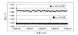
- Magnified micrograph showing the same microprojection shape (after dendrite formation) A graph showing the relationship between capacity and potential, comparing a metal negative electrode having a microprojection shape according to the present invention (roughened) and a metal negative electrode not having a microprojection shape (untreated).
- FIG. 13 is a schematic diagram showing the shape of a microprojection (a cone shape with a curved tip) according to another embodiment of the present invention
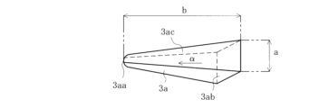
- FIG. 13 is a schematic diagram showing the shape of a minute protrusion (a pyramidal shape with an acute tip) according to another embodiment of the present invention
- FIG. 13 is a schematic diagram showing the shape of a microprojection (a pyramidal shape with a curved tip) according to another embodiment of the present invention
- FIG. 13 is a schematic diagram showing the shape of a microprojection (a cone shape with a truncated tip) according to another embodiment of the present invention
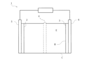
- the metal negative electrode of this embodiment is composed of a metal plate-shaped member applied to a chargeable and dischargeable secondary battery, and the applicable secondary battery 1 is configured to include a metal positive electrode 2, a metal negative electrode 3, a separator 4, a positive electrode side current collector 5, a negative electrode side current collector 6, and a case C containing an alkaline electrolyte (alkaline electrolyte E), as shown in FIG.
- the metal positive electrode 2 is made of a sheet-like member (nickel foil) made of nickel (Ni) and is attached to the surface of the positive electrode side current collector 5, and is configured to be attached to the case C in a state facing the metal negative electrode 3 and separator 4.
- the separator 4 is made of, for example, nonwoven fabric, and is configured to be attached to a position between the metal positive electrode 2 and the metal negative electrode 3 in the case C.
- the metal negative electrode 3 is made of a sheet-like member (zinc foil) made of zinc (Zn) and is attached to the surface of the negative electrode side current collector 6, and is configured to be attached to the case C in a state facing the metal positive electrode 2 and the separator 4.
- the metal negative electrode 3 may be made of a material selected from the group consisting of copper (Cu), lithium (Li), magnesium (Mg), sodium (Na), potassium (K), calcium (Ca), and any of these metals that contain these metals as components or alloys.
- the secondary battery 1 can be charged or discharged by connecting a power source such as a battery or a load such as a motor between the positive electrode side current collector 5 in contact with the metal positive electrode 2 and the negative electrode side current collector 6 in contact with the metal negative electrode 3.
- a power source such as a battery or a load such as a motor
- the secondary battery 1 can convert electrical energy into chemical energy and store it (charge it) by passing a current in the opposite direction to that during discharge.
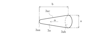
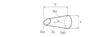
- the metal negative electrode 3 according to this embodiment has a cone-shaped micro-projection shape 3a that tapers continuously toward the tip 3aa, which is integrally formed on the surface H.
- the metal negative electrode 3 according to this embodiment has a plurality of micro-projection shapes 3a formed on its surface H, with the tip 3aa being an acute-angled cone, and those with a ratio of the dimension a (diameter dimension) of the bottom surface 3ab to the height dimension b (dimension from the tip 3aa to the bottom surface 3ab) of 1:3 account for 50% or more of the total micro-projection shapes 3a.
- microprotrusions 3a can be obtained, for example, by dry surface processing (sputtering processing) in which surface H is irradiated with particle beams such as neutral atoms or neutral molecules, or quantum beams such as laser light, and as shown in the micrographs of Figures 5 and 6, a large number of microprotrusions 3a are formed in groups. Furthermore, the surface H including the microprotrusions 3a of the metal negative electrode 3 according to this embodiment has a surface area at least twice as large as the flat surface on which the microprotrusions 3a are not formed.
- dendrites D are generated on the side surface 3ac of the minute protrusion shape 3a, as shown in Fig. 4.
- zinc (Zn) which is the metal negative electrode, dissolves in the electrolyte (such as alkaline electrolyte E), and a chemical reaction of Zn+ 4OH- ⁇ Zn( OH ) 42- + 2e- occurs.
- the electrical energy used during charging further causes a chemical reaction of Zn(OH) 42- ⁇ ZnO+ H2O + 2OH- , and ZnO, known as a dendrite seed, precipitates (see Figs. 7 and 8).
- the ZnO formed on the surface of the metal negative electrode dissolves due to the chemical reaction ZnO + H 2 O + 2OH ⁇ ⁇ Zn(OH) 4 2 ⁇ (see Figures 5 and 6).
- repeated charging and discharging of the secondary battery 1 causes the precipitation of ZnO to continue, gradually growing locally.
- dendrite D precipitated in this embodiment contains insulating oxide (ZnO), it may adversely affect the conductivity of metal negative electrode 3 compared to the initial surface state (Zn) which has excellent conductivity, and may degrade battery performance.
- ZnO insulating oxide
- the metal negative electrode 3 has micro-projection shapes 3a formed on its surface H, and as shown in FIG. 4, the micro-projection shapes 3a are pyramidal (conical) extending in a direction ⁇ perpendicular to the surface H, so that the dendrites D generated on the side surface 3ac grow in a direction shifted by a certain angle from the perpendicular direction ⁇ .
- the separator 4 and metal positive electrode 2 of the secondary battery 1 are attached in the direction ⁇ perpendicular to the surface H of the metal negative electrode 3, so that it is difficult for the tips of the grown dendrites D to reach the separator 4 and metal positive electrode 2, and a short circuit in the secondary battery 1 can be suppressed.
- the metal negative electrode 3 has a plurality of micro-projection shapes 3a formed on its surface H, the surface area is increased, and deterioration of the electrical conductivity of the metal negative electrode 3 can be relatively suppressed even if dendrites D containing insulating oxides (ZnO) are generated. Furthermore, since the micro-projection shapes 3a in this embodiment are formed on the surface H of the metal negative electrode 3 by surface processing (ion beam irradiation processing (also called sputtering processing)), the surface is formed more directly, making it possible to eliminate the need for materials separate from the base material or particles resulting from processing, and simplifying the manufacturing process and materials.
- surface processing ion beam irradiation processing (also called sputtering processing)
- the micro-protrusion shape 3a has a conical shape with an acute-angled tip 3aa as shown in Fig. 3, but it may also have a conical shape with a curved tip 3aa as shown in Fig. 12, a pyramidal shape with an acute-angled tip 3aa as shown in Fig. 13, or a pyramidal shape with a curved tip 3aa as shown in Fig. 14. Also, as shown in Fig. 15, the micro-protrusion shape 3a may have a cut-out shape in which the conical tip 3aa is cut out to form a surface (tip surface).
- the micro-projection shape 3a of the metal negative electrode 3 in this embodiment is formed by dry surface processing in which the surface is irradiated with particle beams such as neutral atoms or neutral molecules, or quantum beams such as laser light or ion beams, or plasma, but is not limited to this.
- the micro-projection shape 3a in the shape of a pyramid having a continuously decreasing diameter toward the tip 3aa may be integrally formed on the surface H by wet surface processing including chemical etching using a solution, and surface processing including dry and wet film formation methods.
- the voltage required for the chemical reaction is greater in the Example than in the Comparative Example.
- the overvoltage for the generation of ZnO, a dendrite species is smaller in the Example. This is thought to be because the Example has a larger surface area due to the unevenness treatment formed compared to the Comparative Example, resulting in a smaller overvoltage per unit area. Therefore, it was found that the Example has less resistance on the electrode surface than the Comparative Example, and that the load applied when current is passed through the metal negative electrode 3 can be reduced.
- Example and Comparative Example were repeatedly discharged and charged, and the voltage was measured each time.
- the Example was able to measure a predetermined voltage even after about 200 discharge and charge cycles
- the Comparative Example was able to measure a predetermined voltage after about 10 discharge and charge cycles, as shown in Figure 11. This demonstrated that the Example had a significantly improved battery characteristic lifespan compared to the Comparative Example.
- the pyramidal micro-projection shape 3a which is continuously tapered toward the tip 3aa, is integrally formed on the surface H, making it possible to eliminate the need for separate particles in the manufacturing process, simplifying the manufacturing process and suppressing dendrites D from growing toward the metal positive electrode 2.
- the micro-projection shape 3a is made of a cone or pyramid with an acute or curved tip 3aa, so that dendrites D from growing toward the metal positive electrode 2 can be reliably suppressed.
- the microprotrusion shapes 3a in the microprotrusion shapes 3a according to this embodiment, those with a ratio of the dimension a of the bottom surface 3ab to the dimension b in the height direction of 1:3 or more account for 50% or more of the entire microprotrusion shapes 3a, so that it is possible to reliably suppress dendrites D growing toward the metal positive electrode 2 while improving the surface area.
- the surface H including the microprotrusion shapes 3a has a surface area at least twice that of a plane on which the microprotrusion shapes 3a are not formed, thereby further improving the surface area.
- the metal negative electrode 3 according to this embodiment is made of a material selected from the group consisting of zinc, copper, lithium, magnesium, sodium, potassium, and calcium, and any of the metals contained in the components or alloys thereof, and can therefore be applied to a general-purpose secondary battery 1.
- the cone-shaped microprojection shape 3a which is continuously reduced in diameter toward the tip 3aa, is integrally formed on the surface, so that the surface of the base material can be deformed to form the microprojection shape 3a, and separate particles, etc. are not required during the manufacturing process.
- the applicable secondary battery 1 is not limited to rocking chair type secondary batteries such as zinc-air secondary batteries, zinc-nickel secondary batteries, zinc-silver secondary batteries, lithium-air secondary batteries, lithium-sulfur secondary batteries, magnesium-air secondary batteries, sodium-sulfur secondary batteries, potassium secondary batteries, calcium secondary batteries, and multivalent ion secondary batteries, but may also be any one of the systems that do not utilize a redox reaction in the positive electrode, such as a lithium ion capacitor.
Landscapes
- Battery Electrode And Active Subsutance (AREA)
- Electric Double-Layer Capacitors Or The Like (AREA)
- Secondary Cells (AREA)
Abstract
製造プロセスを簡素化することができるとともに、正極に向かって成長するデンドライトを抑制することができる二次電池の金属負極およびその製造方法を提供する。 充電および放電可能な二次電池1の金属負極3において、突端3aaに向かって連続的に縮径した錘状の微小突出形状3aが表面Hに一体形成されるとともに、微小突出形状3aは、突端3aaが鋭角若しくは湾曲した円錐または角錐から成り、底面の寸法aと高さ方向の寸法bとの比が1:3以上とされたものが全体の微小突出形状3aの50%以上を占めるものである。
Description
本発明は、充電および放電可能な二次電池の金属負極およびその製造方法に関するものである。
電気自動車や電動バイクなどのEV(Electric Vehicle)は、航続距離の延長が重要な課題とされており、その課題を解決するためには、車両が搭載する二次電池の高容量化と高電圧化が必要とされている。このような二次電池の高容量化と高電圧化を図る上で、種々の問題があり、そのうちの一つに二次電池の金属負極に生じるデンドライトの問題が挙げられる。
かかるデンドライトは、二次電池の充電および放電を行うことにより金属負極に発生する針状の突起部から成り、充電および放電の繰り返しにより成長するものである。このようなデンドライトが成長すると、セパレータを貫通し、突端が正極に接触して短絡させてしまう虞がある。そこで、従来、例えば特許文献1にて開示されるように、金属負極表面に粒子を融合して突起部を予め形成してデンドライトの成長を抑制する技術が開示されている。
しかしながら、上記従来技術においては、リチウムイオン二次電池の金属負極表面に粒子を融合して突起部を形成しているため、母材とは別個の粒子が必要とされ、製造プロセスが複雑となって製造コストが嵩んでしまうとともに、正極に向かって成長するデンドライトを抑制するには不十分とされ、その結果、二次電池の充電および放電を長期にわたって繰り返し行った場合、成長したデンドライトの突端が正極に接触して短絡してしまう虞がある。
本発明は、このような事情に鑑みてなされたもので、製造プロセスを簡素化することができるとともに、正極に向かって成長するデンドライトを抑制することができる二次電池の金属負極およびその製造方法を提供することにある。
請求項1記載の発明は、充電および放電可能な二次電池の金属負極において、突端に向かって連続的に縮径した錘状の微小突出形状が表面に一体形成されたことを特徴とする。
請求項2記載の発明は、請求項1記載の二次電池の金属負極において、前記微小突出形状は、突端が鋭角若しくは湾曲した円錐または角錐から成ることを特徴とする。
請求項3記載の発明は、請求項2記載の二次電池の金属負極において、前記微小突出形状は、底面の寸法と高さ方向の寸法との比が1:3以上とされたものが全体の微小突出形状の50%以上を占めることを特徴とする。
請求項4記載の発明は、請求項1記載の二次電池の金属負極において、前記微小突出形状を含む表面は、前記微小突出形状が形成されない平面に対して少なくとも2倍以上の表面積とされたことを特徴とする。
請求項5記載の発明は、請求項1記載の二次電池の金属負極において、亜鉛、銅、リチウム、マグネシウム、ナトリウム、カリウムおよびカルシウム、並びにこれらの金属を成分に含むもしくは合金のいずれかからなる群より選ばれる材質から成ることを特徴とする。
請求項6記載の発明は、充電および放電可能な二次電池の金属負極の製造方法において、表面に中性原子若しくは中性分子などの粒子線またはレーザ光若しくはイオンビームなどの量子線やプラズマを照射する乾式表面加工、溶液による化学エッチングを含む湿式表面加工、並びに乾式および湿式の成膜法を含む表面加工により、突端に向かって連続的に縮径した錘状の微小突出形状を表面に一体形成することを特徴とする。
本発明によれば、突端に向かって連続的に縮径した錘状の微小突出形状が表面に一体形成されたので、製造プロセスを簡素化することができるとともに、正極に向かって成長するデンドライトを抑制することができる。
以下、本発明の実施形態について図面を参照しながら具体的に説明する。
本実施形態に係る金属負極は、充電および放電可能な二次電池に適用された金属製板状部材から成るもので、適応される二次電池1は、図1に示すように、金属正極2と、金属負極3と、セパレータ4と、プラス極側集電体5と、マイナス極側集電体6と、アルカリ性の電解液(アルカリ電解液E)を収容したケースCとを具備して構成されている。
本実施形態に係る金属負極は、充電および放電可能な二次電池に適用された金属製板状部材から成るもので、適応される二次電池1は、図1に示すように、金属正極2と、金属負極3と、セパレータ4と、プラス極側集電体5と、マイナス極側集電体6と、アルカリ性の電解液(アルカリ電解液E)を収容したケースCとを具備して構成されている。
金属正極2は、ニッケル(Ni)から成るシート状部材(ニッケル箔)から成り、プラス極側集電体5の表面に取り付けられるとともに、金属負極3及びセパレータ4と対向した状態にてケースCに取り付けられるよう構成されている。セパレータ4は、例えば不織布から成り、ケースCにおける金属正極2と金属負極3との間の位置に取り付けられるよう構成されている。
金属負極3は、亜鉛(Zn)から成るシート状部材(亜鉛箔)から成り、マイナス極側集電体6の表面に取り付けられるとともに、金属正極2及びセパレータ4と対向した状態にてケースCに取り付けられるよう構成されている。かかる金属負極3は、亜鉛の他、銅(Cu)、リチウム(Li)、マグネシウム(Mg)、ナトリウム(Na)、カリウム(K)およびカルシウム(Ca)、並びにこれらの金属を成分に含むもしくは合金のいずれかからなる群より選ばれる材質から成るものとしてもよい。
そして、金属正極2と接触したプラス極側集電体5と金属負極3と接触したマイナス極側集電体6との間にバッテリ等の電源またはモータ等の負荷を接続することにより二次電池1の充電または放電が可能とされている。すなわち、二次電池1によれば、放電時と逆方向に電流を流すことにより、電気エネルギーを化学エネルギーに変換して蓄積(充電)することが可能とされているのである。
ここで、本実施形態に係る金属負極3は、図2、3に示すように、突端3aaに向かって連続的に縮径した錘状の微小突出形状3aが表面Hに一体形成されている。具体的には、本実施形態に係る金属負極3は、その表面Hに突端3aaが鋭角の円錐から成る微小突出形状3aが複数形成されており、底面3abの寸法a(径寸法)と高さ寸法b(突端3aaから底面3abまでの寸法)との比が1:3とされたものが全体の微小突出形状3aの50%以上を占めるものとされている。
かかる微小突出形状3aは、例えば表面Hに中性原子若しくは中性分子などの粒子線またはレーザ光などの量子線を照射する乾式表面加工(スパッタリング加工)で得ることができ、図5、6の顕微鏡写真に示すように、多数の微小突出形状3aが群を成して形成されている。また、本実施形態に係る金属負極3の微小突出形状3aを含む表面Hは、微小突出形状3aが形成されない平面に対して少なくとも2倍以上の表面積とされている。
そして、本実施形態に係る二次電池1を充電または放電すると、図4に示すように、微小突出形状3aの側面3acにデンドライトDが発生することとなる。具体的には、金属負極である亜鉛(Zn)が電解質(アルカリ電解液E等)中に溶解し、Zn+4OH-→Zn(OH)4
2-+2e-の化学反応が生じる。そして、二次電池1の充電時には、充電時の電気エネルギーによって更にZn(OH)4
2-→ZnO+H2O+2OH-の化学反応が生じ、デンドライト種として知られているZnOが析出する(図7、8参照)。
デンドライトDは、二次電池1の放電時は、ZnO+H2O+2OH-→Zn(OH)4
2-なる化学反応により金属負極表面に生じたZnOが溶解(図5、6参照)するものであるが、二次電池1の充電および放電を繰り返す事でZnOの析出が続き、次第に局所的に成長する事となる。
このように、デンドライトDが成長すると、その突端がセパレータ4を突き破って金属正極2に達してしまう可能性があり、デンドライトDの突端が金属正極2に接触すると短絡して二次電池1の機能を喪失することとなる。また、本実施形態において析出されるデンドライトDは、絶縁性の酸化物(ZnO)を含むため、導電性に優れた初期の表面状態(Zn)と比べて金属負極3の導電性に悪影響を及ぼし、電池性能を劣化させる虞がある。
これに対し、本実施形態に係る金属負極3は、その表面Hに微小突出形状3aが形成されており、当該微小突出形状3aは、図4に示すように、表面Hに対して垂直方向αに向かって延設された錘状(円錐状)とされているため、側面3acに発生したデンドライトDは、垂直方向αから所定角度ずれた方向に向かって成長することとなる。一方、二次電池1のセパレータ4および金属正極2は、金属負極3の表面Hに対して垂直方向αに取り付けられるため、成長したデンドライトDの突端がセパレータ4および金属正極2に到達するのは困難となり、二次電池1の短絡を抑制することができる。
しかるに、金属負極3は、その表面Hに微小突出形状3aが複数形成されているので、表面積が増加することとなり、絶縁性の酸化物(ZnO)を含むデンドライトDが発生しても金属負極3の導電性の劣化を比較的抑制することができる。また、本実施形態に係る微小突出形状3aは、金属負極3の表面Hに表面加工(イオンビーム照射加工(スパッタリング加工とも称される))により形成されるため、より直接的に表面が形成されることとなり、母材とは別個となる材料もしくは加工による粒子等を不要とすることができ、製造プロセス及び材料を簡素化することができる。
なお、本実施形態に係る微小突出形状3aは、図3に示すように、突端3aaが鋭角の円錐形状とされているが、図12に示すように、突端3aaが湾曲した円錐形状、図13に示すように、突端3aaが鋭角の角錐形状、図14に示すように、突端3aaが湾曲した角錐形状としてもよい。また、図15に示すように、円錐形状の突端3aaが切欠かれて面状(突端面)に形成された接切形状の微小突出形状3aとしてもよい。
本実施形態に係る金属負極3の微小突出形状3aは、表面に中性原子若しくは中性分子などの粒子線またはレーザ光若しくはイオンビームなどの量子線やプラズマを照射する乾式表面加工にて形成されているが、これに限定されるものではなく、溶液による化学エッチングを含む湿式表面加工、並びに乾式および湿式の成膜法を含む表面加工により、突端3aaに向かって連続的に縮径した錘状の微小突出形状3aを表面Hに一体形成するようにしてもよい。
次に、本実施形態に係る金属負極3の技術的優位性を示す実験結果について説明する。
縦1cm、横1cm及び厚さ50μmの亜鉛箔(Zn)の表面にスパッタリング加工を施して微小突出形状3aを形成した実施例(凹凸処理)と、縦1cm、横1cm及び厚さ50μmの亜鉛箔(Zn)の表面に加工を施さず平坦な面とされた比較例(未処理)とを用意し、それぞれに0.1mA/cm2の電流を流して二次電池1の充電時に発生する化学反応Zn(OH)4 2-→ZnO+H2O+2OH-と電圧の関係を観察した。
縦1cm、横1cm及び厚さ50μmの亜鉛箔(Zn)の表面にスパッタリング加工を施して微小突出形状3aを形成した実施例(凹凸処理)と、縦1cm、横1cm及び厚さ50μmの亜鉛箔(Zn)の表面に加工を施さず平坦な面とされた比較例(未処理)とを用意し、それぞれに0.1mA/cm2の電流を流して二次電池1の充電時に発生する化学反応Zn(OH)4 2-→ZnO+H2O+2OH-と電圧の関係を観察した。
その結果、図9に示すように、実施例は、比較例と比べて化学反応に必要な電圧が大きい。すなわち、デンドライト種であるZnO発生の過電圧は実施例の方が小さい。これは、実施例が比較例に比べて凹凸処理を形成した事に起因して表面積が大きいため、単位面積あたりの過電圧が小さくなったと考えられる。したがって、実施例は、比較例と比べて電極表面上の抵抗が少ないことが分かり、金属負極3に電流を流した際に付与される負荷を低減できることが分かった。
続いて、実施例と比較例とに対し、繰り返し放電および充電を繰り返し、都度、電圧を測定する実験を行った。その結果、実施例は、図10で示すように、放電および充電を200回程度繰り返しても所定の電圧が測定されるのに対し、比較例は、図11で示すように、放電および充電を10回程度繰り返した時点で所定の電圧が測定されなくなった。これにより、実施例は、比較例に比べて電池特性の寿命が著しく向上することが分かった。
本実施形態によれば、突端3aaに向かって連続的に縮径した錘状の微小突出形状3aが表面Hに一体形成されたので、製造過程にて別個の粒子等を不要とすることができ、製造プロセスを簡素化することができるとともに、金属正極2に向かって成長するデンドライトDを抑制することができる。特に、微小突出形状3aは、突端3aaが鋭角若しくは湾曲した円錐または角錐から成るので、金属正極2に向かって成長するデンドライトDを確実に抑制することができる。
また、本実施形態に係る微小突出形状3aは、底面3abの寸法aと高さ方向の寸法bとの比が1:3以上とされたものが全体の微小突出形状3aの50%以上を占めるので、表面積を向上させつつ金属正極2に向かって成長するデンドライトDを確実に抑制することができる。さらに、本実施形態の如く微小突出形状3aを含む表面Hは、微小突出形状3aが形成されない平面に対して少なくとも2倍以上の表面積とされることにより、より一層表面積を向上させることができる。
またさらに、本実施形態に係る金属負極3は、亜鉛、銅、リチウム、マグネシウム、ナトリウム、カリウムおよびカルシウム、並びにこれらの金属を成分に含むもしくは合金のいずれかからなる群より選ばれる材質から成るので、汎用的な二次電池1に適用することができる。また、表面Hに中性原子若しくは中性分子などの粒子線またはレーザ光などの量子線を照射する乾式表面加工、溶液による化学エッチングを含む湿式表面加工、並びに乾式および湿式の成膜法を含む表面加工により、突端3aaに向かって連続的に縮径した錘状の微小突出形状3aを表面に一体形成するので、母材の表面を変形させて微小突出形状3aを形成することができ、製造過程で別個の粒子等を不要とすることができる。
以上、本実施形態について説明したが、本発明はこれに限定されず、例えば適用される二次電池1は、亜鉛空気二次電池、亜鉛ニッケル二次電池、亜鉛銀二次電池、リチウム空気二次電池、リチウム硫黄二次電池、マグネシウム空気二次電池、ナトリウム硫黄二次電池、カリウム二次電池、カルシウム二次電池、多価イオン二次電池等のロッキングチェア型の二次電池に限らず、リチウムイオンキャパシタなど正極にレドックス反応を利用しない系いずれか一つとしてもよい。
本発明と同様の趣旨であれば、外観形状が異なるもの或いは他の機能が付加されたもの等にも適用することができる。
1 二次電池
2 金属正極
3 金属負極
3a 微小突出形状
3aa 突端
3ab 底面
3ac 側面
4 セパレータ
5 プラス極側集電体
6 マイナス極側集電体
C ケース
H 表面
D デンドライト
E 電解液
2 金属正極
3 金属負極
3a 微小突出形状
3aa 突端
3ab 底面
3ac 側面
4 セパレータ
5 プラス極側集電体
6 マイナス極側集電体
C ケース
H 表面
D デンドライト
E 電解液
Claims (6)
- 充電および放電可能な二次電池の金属負極において、
突端に向かって連続的に縮径した錘状の微小突出形状が表面に一体形成されたことを特徴とする二次電池の金属負極。 - 前記微小突出形状は、突端が鋭角若しくは湾曲した円錐または角錐から成ることを特徴とする請求項1記載の二次電池の金属負極。
- 前記微小突出形状は、底面の寸法と高さ方向の寸法との比が1:3以上とされたものが全体の微小突出形状の50%以上を占めることを特徴とする請求項2記載の二次電池の金属負極。
- 前記微小突出形状を含む表面は、前記微小突出形状が形成されない平面に対して少なくとも2倍以上の表面積とされたことを特徴とする請求項1記載の二次電池の金属負極。
- 亜鉛、銅、リチウム、マグネシウム、ナトリウム、カリウムおよびカルシウム、並びにこれらの金属を成分に含むもしくは合金のいずれかからなる群より選ばれる材質から成ることを特徴とする請求項1記載の二次電池の金属負極。
- 充電および放電可能な二次電池の金属負極の製造方法において、
表面に中性原子若しくは中性分子などの粒子線またはレーザ光若しくはイオンビームなどの量子線やプラズマを照射する乾式表面加工、溶液による化学エッチングを含む湿式表面加工、並びに乾式および湿式の成膜法を含む表面加工により、突端に向かって連続的に縮径した錘状の微小突出形状を表面に一体形成することを特徴とする二次電池の金属負極の製造方法。
Applications Claiming Priority (2)
| Application Number | Priority Date | Filing Date | Title |
|---|---|---|---|
| JP2023-092761 | 2023-06-05 | ||
| JP2023092761A JP2024174755A (ja) | 2023-06-05 | 2023-06-05 | 二次電池の金属負極およびその製造方法 |
Publications (1)
| Publication Number | Publication Date |
|---|---|
| WO2024253053A1 true WO2024253053A1 (ja) | 2024-12-12 |
Family
ID=93795959
Family Applications (1)
| Application Number | Title | Priority Date | Filing Date |
|---|---|---|---|
| PCT/JP2024/020160 Ceased WO2024253053A1 (ja) | 2023-06-05 | 2024-06-03 | 二次電池の金属負極およびその製造方法 |
Country Status (2)
| Country | Link |
|---|---|
| JP (1) | JP2024174755A (ja) |
| WO (1) | WO2024253053A1 (ja) |
Cited By (1)
| Publication number | Priority date | Publication date | Assignee | Title |
|---|---|---|---|---|
| CN119695089A (zh) * | 2025-02-21 | 2025-03-25 | 西安稀有金属材料研究院有限公司 | 改性锌负极的制备方法、水系锌离子电池 |
Citations (5)
| Publication number | Priority date | Publication date | Assignee | Title |
|---|---|---|---|---|
| JPH0888022A (ja) * | 1994-07-19 | 1996-04-02 | Canon Inc | 二次電池及び該二次電池の製造方法 |
| JP2013214411A (ja) * | 2012-04-02 | 2013-10-17 | Tokyo Ohka Kogyo Co Ltd | リチウムイオン二次電池用負極、リチウムイオン二次電池及びリチウムイオン二次電池用負極の製造方法 |
| US20150064567A1 (en) * | 2013-08-29 | 2015-03-05 | Stmicroelectronics (Tours) Sas | Silicon microstructuring method and microbattery |
| JP2016207664A (ja) * | 2011-08-31 | 2016-12-08 | 株式会社半導体エネルギー研究所 | 蓄電装置 |
| JP2022187895A (ja) * | 2021-06-08 | 2022-12-20 | 国立大学法人東海国立大学機構 | リチウムイオン二次電池の負極とその製造方法および製造装置ならびにリチウムイオン二次電池 |
-
2023
- 2023-06-05 JP JP2023092761A patent/JP2024174755A/ja active Pending
-
2024
- 2024-06-03 WO PCT/JP2024/020160 patent/WO2024253053A1/ja not_active Ceased
Patent Citations (5)
| Publication number | Priority date | Publication date | Assignee | Title |
|---|---|---|---|---|
| JPH0888022A (ja) * | 1994-07-19 | 1996-04-02 | Canon Inc | 二次電池及び該二次電池の製造方法 |
| JP2016207664A (ja) * | 2011-08-31 | 2016-12-08 | 株式会社半導体エネルギー研究所 | 蓄電装置 |
| JP2013214411A (ja) * | 2012-04-02 | 2013-10-17 | Tokyo Ohka Kogyo Co Ltd | リチウムイオン二次電池用負極、リチウムイオン二次電池及びリチウムイオン二次電池用負極の製造方法 |
| US20150064567A1 (en) * | 2013-08-29 | 2015-03-05 | Stmicroelectronics (Tours) Sas | Silicon microstructuring method and microbattery |
| JP2022187895A (ja) * | 2021-06-08 | 2022-12-20 | 国立大学法人東海国立大学機構 | リチウムイオン二次電池の負極とその製造方法および製造装置ならびにリチウムイオン二次電池 |
Cited By (1)
| Publication number | Priority date | Publication date | Assignee | Title |
|---|---|---|---|---|
| CN119695089A (zh) * | 2025-02-21 | 2025-03-25 | 西安稀有金属材料研究院有限公司 | 改性锌负极的制备方法、水系锌离子电池 |
Also Published As
| Publication number | Publication date |
|---|---|
| JP2024174755A (ja) | 2024-12-17 |
Similar Documents
| Publication | Publication Date | Title |
|---|---|---|
| EP2973803B1 (en) | Iron-sulphide-based battery and anode | |
| JP5273123B2 (ja) | リチウムイオン二次電池システムおよびリチウムイオン二次電池の運転方法 | |
| JP5626607B2 (ja) | リチウム二次電池の製造方法 | |
| CN103782441B (zh) | 锂二次电池的制造方法 | |
| JP2015076379A (ja) | 金属空気二次電池 | |
| KR20190079428A (ko) | 금속 황화물 이차전지 | |
| CN112820852A (zh) | 一种负极片和锂离子电池 | |
| JP3768026B2 (ja) | 非水電解液二次電池 | |
| JP2024174755A (ja) | 二次電池の金属負極およびその製造方法 | |
| JP2013097925A (ja) | リチウム二次電池の電極の製造方法、リチウム二次電池の電極及びリチウム二次電池 | |
| CN108432028B (zh) | 用于具有金属基负极的锂离子电池的高电流处理 | |
| CN111201638A (zh) | 极板、蓄电元件和极板的制造方法 | |
| US12046743B2 (en) | Cathode active material, method for preparing same, and lithium secondary battery comprising same | |
| JPH06310126A (ja) | 非水電解質二次電池 | |
| JP7279632B2 (ja) | 全固体電池 | |
| JP2020123535A (ja) | 全固体電池用負極 | |
| JP4497828B2 (ja) | ニッケル−水素蓄電池および組電池 | |
| KR102958975B1 (ko) | 이차 전지용 음극 및 이의 제조 방법 | |
| JP2024144832A (ja) | 蓄電装置の電極の回復方法、蓄電装置の製造方法及び蓄電装置 | |
| JP2009245771A (ja) | アルカリ蓄電池およびその製造方法 | |
| JP2019079755A (ja) | 非水電電解質用負極、その製造方法、及びそれを用いた非水電解質二次電池 | |
| JP2006073541A (ja) | アルカリ亜鉛蓄電池 | |
| KR20150133376A (ko) | 리튬 이차 전지용 전극, 이의 형성 방법 및 리튬 이차 전지 | |
| JP2823301B2 (ja) | 水素吸蔵合金電極 | |
| JP5092277B2 (ja) | 二次電池用電極およびその製造方法 |
Legal Events
| Date | Code | Title | Description |
|---|---|---|---|
| 121 | Ep: the epo has been informed by wipo that ep was designated in this application |
Ref document number: 24819283 Country of ref document: EP Kind code of ref document: A1 |
|
| NENP | Non-entry into the national phase |
Ref country code: DE |