WO2024253017A1 - トルク検出装置を備えた波動歯車装置 - Google Patents
トルク検出装置を備えた波動歯車装置 Download PDFInfo
- Publication number
- WO2024253017A1 WO2024253017A1 PCT/JP2024/019899 JP2024019899W WO2024253017A1 WO 2024253017 A1 WO2024253017 A1 WO 2024253017A1 JP 2024019899 W JP2024019899 W JP 2024019899W WO 2024253017 A1 WO2024253017 A1 WO 2024253017A1
- Authority
- WO
- WIPO (PCT)
- Prior art keywords
- strain gauges
- torque
- output
- detection unit
- torque detection
- Prior art date
- Legal status (The legal status is an assumption and is not a legal conclusion. Google has not performed a legal analysis and makes no representation as to the accuracy of the status listed.)
- Ceased
Links
Images



Classifications
-
- G—PHYSICS
- G01—MEASURING; TESTING
- G01L—MEASURING FORCE, STRESS, TORQUE, WORK, MECHANICAL POWER, MECHANICAL EFFICIENCY, OR FLUID PRESSURE
- G01L3/00—Measuring torque, work, mechanical power, or mechanical efficiency, in general
- G01L3/02—Rotary-transmission dynamometers
- G01L3/14—Rotary-transmission dynamometers wherein the torque-transmitting element is other than a torsionally-flexible shaft
- G01L3/1464—Rotary-transmission dynamometers wherein the torque-transmitting element is other than a torsionally-flexible shaft involving screws and nuts, screw-gears or cams
-
- G—PHYSICS
- G01—MEASURING; TESTING
- G01L—MEASURING FORCE, STRESS, TORQUE, WORK, MECHANICAL POWER, MECHANICAL EFFICIENCY, OR FLUID PRESSURE
- G01L3/00—Measuring torque, work, mechanical power, or mechanical efficiency, in general
- G01L3/02—Rotary-transmission dynamometers
- G01L3/14—Rotary-transmission dynamometers wherein the torque-transmitting element is other than a torsionally-flexible shaft
-
- G—PHYSICS
- G01—MEASURING; TESTING
- G01L—MEASURING FORCE, STRESS, TORQUE, WORK, MECHANICAL POWER, MECHANICAL EFFICIENCY, OR FLUID PRESSURE
- G01L3/00—Measuring torque, work, mechanical power, or mechanical efficiency, in general
- G01L3/02—Rotary-transmission dynamometers
- G01L3/14—Rotary-transmission dynamometers wherein the torque-transmitting element is other than a torsionally-flexible shaft
- G01L3/1407—Rotary-transmission dynamometers wherein the torque-transmitting element is other than a torsionally-flexible shaft involving springs
- G01L3/1428—Rotary-transmission dynamometers wherein the torque-transmitting element is other than a torsionally-flexible shaft involving springs using electrical transducers
- G01L3/1457—Rotary-transmission dynamometers wherein the torque-transmitting element is other than a torsionally-flexible shaft involving springs using electrical transducers involving resistance strain gauges
-
- G—PHYSICS
- G01—MEASURING; TESTING
- G01L—MEASURING FORCE, STRESS, TORQUE, WORK, MECHANICAL POWER, MECHANICAL EFFICIENCY, OR FLUID PRESSURE
- G01L5/00—Apparatus for, or methods of, measuring force, work, mechanical power, or torque, specially adapted for specific purposes
- G01L5/0009—Force sensors associated with a bearing
- G01L5/0019—Force sensors associated with a bearing by using strain gages, piezoelectric, piezo-resistive or other ohmic-resistance based sensors
Definitions
- the present invention relates to a strain gauge type torque detector that detects the torque transmitted through a flexible external gear.
- Wave gear devices equipped with strain gauge-type torque detection devices have been proposed in Patent Documents 1 to 3.
- To accurately detect torque in a wave gear device it is necessary to be able to remove rotational ripple, which is a periodic error component contained in the strain gauge output signal that occurs regardless of the transmitted torque, and to improve the linearity of the detection output.
- multiple sets of strain gauges are used to be able to compensate for elliptical distortion, which is a periodic error component contained in the detection output due to the rotation of the wave generator.
- the torque detection section 20 of this embodiment is divided into a first torque detection section 20A and a second torque detection section 20B which output two independent systems of detection signals.
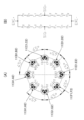
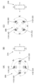
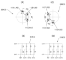
- the first torque detection section 20A of the torque detection section 20 includes four sets of strain gauges 11 (A1, A2), 11 (C1, C2), 11 (E1, E2), and 11 (G1, G2) arranged at 90° intervals, and as shown in Fig. 4B, these four sets of strain gauges form a first Wheatstone bridge circuit 21A.
- Fig. 4A strain gauges
- the second torque detection section 20B includes the remaining four sets of strain gauges 11 (B1, B2), 11 (D1, D2), 11 (F1, F2), and 11 (H1, H2) arranged at 90° intervals, and as shown in Fig. 4D, these sets form a second Wheatstone bridge circuit 21B.
- a first detection signal 22A which is an output signal of the first Wheatstone bridge circuit 21A constituting the first torque detection section 20A
- a second detection signal 22B which is an output signal of the second Wheatstone bridge circuit 21B constituting the second torque detection section 20B, are supplied to the signal processing unit 30 via cable wiring 40.
- the signal processing unit 30 includes a first amplifier 31A for adjusting the gain of the first detection signal 22A, a second amplifier 31B for adjusting the gain of the second detection signal 22B independently of the first amplifier 31A, and an output synthesis unit 31C for synthesizing the first detection signal 23A and the second detection signal 23B after the gain adjustment to generate a synthesis signal 23C.
- the signal processing unit 30 also includes a calculation unit 32 for calculating the transmission torque based on the first detection signal 23A after the gain adjustment, the second detection signal 23B after the gain adjustment, and the synthesis signal 23C, and an output port 33.
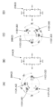
- the torque detection section is divided into a first torque detection section 20A(2) having a first Wheatstone bridge circuit 21A(2) consisting of four sets of strain gauges 11(A1, A2), 11(C1, C2), 11(F1, F2), and 11(H1, H2) as shown in FIG. 6(A) and (B), and a second torque detection section 20B(2) having a second Wheatstone bridge circuit 21B(2) consisting of the remaining four sets of strain gauges 11(B1, B2), 11(D1, D2), 11(E1, E2), and 11(G1, G2) as shown in FIG. 6(C) and (D).
- FIG. 8 an example in which the torque detection unit 20(3) is divided into two independent systems (a first torque detection unit 20A and a second torque detection unit 20B) is shown in FIG. 8 and FIG. 8 is divided into a first torque detection section 20A(3) including a first bridge circuit 21A(3) consisting of three sets of strain gauges 11 (A1, A2) to 11 (C1, C2), and a second torque detection section 20B(3) including a second bridge circuit 21B(3) consisting of the remaining three sets of strain gauges 11 (D1, D2) to 11 (F1, F2).
- Torque detection is performed based on the detection outputs from the three sets of strain gauges 11 that make up the first bridge circuit 21A(3) and the detection outputs from the three sets of strain gauges 11 that make up the second bridge circuit 21B(3).
- FIG. 9 shows another example of a two-system torque detection unit 20(3) in the case of six strain gauges arranged at 60° (see FIG. 7).
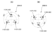
- the torque detection unit is divided into a first torque detection unit 20A(4) having a first bridge circuit (not shown) consisting of three sets of strain gauges 11(A1, A2), 11(C1, C2), and 11(E1, E2), and a second torque detection unit 20B(4) having a second bridge circuit (not shown) consisting of the remaining three sets of strain gauges 11(B1, B2), 11(D1, D2), and 11(F1, F2).
- the transmission torque can be calculated based on each of the three systems of output.
- the broken line Lb shows the error component ratio contained in the second torque detection signal obtained from the second torque detection unit.
- the broken line Lb is obtained by shifting the phase of the broken line La, which is the actual measurement value, by 30°.
- the broken line Lc (addition of two signals) shows the error component ratio contained in the composite signal obtained by combining the first torque detection signal and the second torque detection signal. As can be seen from the graph, the sixth-order periodic error component contained in the torque detection signal is significantly reduced.
- the strain gauge is attached to the diaphragm of a top hat shaped external gear.
- the strain gauge may be attached to a surface portion of the cylindrical body of the external gear other than the portion where the external teeth are formed.
- the present invention is also similarly applicable to a strain gear device with a cup-shaped external gear and a strain gear device with a cylindrical external gear.
- a two-axis stacked arrangement type is used as the two-axis orthogonal strain gauge.
- Two-axis planar arrangement type is also known as a two-axis orthogonal strain gauge, and it goes without saying that this type of two-axis orthogonal strain gauge may also be used.
Landscapes
- Physics & Mathematics (AREA)
- General Physics & Mathematics (AREA)
- Chemical & Material Sciences (AREA)
- Analytical Chemistry (AREA)
- Retarders (AREA)
- Force Measurement Appropriate To Specific Purposes (AREA)
Abstract
Description
前記トルク検出装置は、
独立した2系統の検出信号を出力する第1トルク検出部および第2トルク検出部と、
前記第1トルク検出部の前記検出信号である第1検出信号と前記第2トルク検出部の前記検出信号である第2検出信号とを合成して合成信号を生成する出力合成部と、
前記第1検出信号、前記第2検出信号および前記合成信号のそれぞれに基づき前記伝達トルクを算出可能な演算部と、
を備えており、
前記第1トルク検出部は、前記外歯歯車の中心軸線を中心として当該外歯歯車の表面に所定の角度間隔で貼り付けた第1群の歪ゲージを備えた歪ゲージ式のトルク検出部であり、
前記第2トルク検出部は、前記外歯歯車の中心軸線を中心として当該外歯歯車の表面に所定の角度間隔で貼り付けた第2群の歪ゲージを備えた歪ゲージ式のトルク検出部であることを特徴としている。
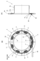
図1は本発明を適用した波動歯車装置を示す概略縦断面図である。図2(A)は外歯歯車を示す縦断面図であり、図2(B)はトルク検出部が取り付けられている外歯歯車の端面図である。
波動歯車装置1は、剛性の内歯歯車2と、この内側に同軸に配置された可撓性の外歯歯車3と、この内側に同軸に嵌め込まれた楕円状輪郭の波動発生器4と、内歯歯車2および外歯歯車3を相対回転自在の状態で支持しているクロスローラベアリング5と、中空入力軸6と、軸方向の一方の側に配置されたエンドプレート7と、軸方向の他方の側に配置されたエンドプレート8とを備えている。中空入力軸6の両側の軸端部は、それぞれ、ボールベアリング9a、9bを介して、エンドプレート7、8によって支持されている。
波動歯車装置1には、外歯歯車3を介して伝達される伝達トルクを検出するトルク検出装置10が付設されている。トルク検出装置10は、外歯歯車3に取り付けたトルク検出部20と、波動歯車装置1の外部に配置された信号処理ユニット30と、トルク検出部20および信号処理ユニット30の間を接続するケーブル配線40とを備えている。トルク検出部20は、外歯歯車3のダイヤフラム3cに貼り付けた複数組の歪ゲージ11およびフレキシブルプリント配線基板12を備えている。本例では、図2(B)に示すように、外歯歯車3の中心軸線回りに、45°の等角度間隔で配列された8組の歪ゲージを備えている。各歪ゲージ11は、図2(A)において網掛け部分で示すように、コーティング層13によって保護されている。また、フレキシブルプリント配線基板12に形成した配線パターン(図示せず)によって、相互に結線されている。
本例のトルク検出部20は、図4に示すように、独立した2系統の検出信号を出力する第1トルク検出部20Aおよび第2トルク検出部20Bに分かれている。
図4(A)に示すように、トルク検出部20の第1トルク検出部20Aは、90°間隔で配置された4組の歪ゲージ11(A1,A2)、11(C1,C2)、11(E1,E2)および11(G1,G2)を備え、図4(B)に示すように、これら4組の歪ゲージにより、第1ホイートストンブリッジ回路21Aが組まれている。同様に、第2トルク検出部20Bは、図4(C)に示すように、残りの90°間隔で配置された4組の歪ゲージ11(B1,B2)、11(D1,D2)、11(F1,F2)および11(H1,H2)を備え、これらにより、図4(D)に示すように、第2ホイートストンブリッジ回路21Bが組まれている。第1トルク検出部20Aを構成する第1ホイートストンブリッジ回路21Aの出力信号である第1検出信号22A、および第2トルク検出部20Bを構成する第2ホイートストンブリッジ回路21Bの出力信号である第2検出信号22Bは、ケーブル配線40を介して、信号処理ユニット30に供給される。
図7にはトルク検出部20の別の例を示してあり、この図に示すトルク検出部20(3)は、外歯歯車のダイヤフラムに、中心軸線回りに60°の等角度間隔に貼り付けた6組の歪ゲージ11(A1,A2)~11(F1,F2)を備えた構成となっている(歪ゲージ6か所60°配置)。
図8に示すトルク検出部20は、3組の歪ゲージ11(A1,A2)~11(C1,C2)から構成される第1ブリッジ回路21A(3)を備えた第1トルク検出部20A(3)と、残りの3組の歪ゲージ11(D1,D2)~11(F1,F2)から構成される第2ブリッジ回路21B(3)を備えた第2トルク検出部20B(3)とに分けられている。第1ブリッジ回路21A(3)を構成する3組の歪ゲージ11のそれぞれからの検出出力、および第2ブリッジ回路21B(3)を構成する3組の歪ゲージ11のそれぞれからの検出出力に基づき、トルク検出が行われる。
図10(A)には、独立した2系統の第1トルク検出部および第2トルク検出部を備えたトルク検出部20の別の例を示してあり、この図に示すトルク検出部20(5)は、外歯歯車のダイヤフラムに貼り付けた6組の歪ゲージ11(A1,A2)~11(F1,F2)を備えている。図10(B)に示すように、第1トルク検出部20A(5)を構成する3組の歪ゲージ11(A1,A2)、11(C1,C2)および11(E1,E2)は、ダイヤフラムの中心軸線回りに120°の等角度間隔に貼り付けられている。図10(C)に示すように、第2トルク検出部20B(5)を構成する残りの3組の歪ゲージ11(B1,B2)、11(D1,D2)および11(F1,F2)も、ダイヤフラムの中心軸線回りに120°の等角度間隔に貼り付けられている。さらに、120°の角度間隔で配置した3組の歪ゲージ11(A1,A2)、11(C1,C2)および11(E1,E2)のそれぞれに対して、30°回転した角度位置に、3組の歪ゲージ11(B1,B2)、11(D1,D2)および11(F1,F2)のそれぞれが位置している。
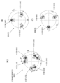
図11(B)に示すグラフにおいて、折れ線La(実測値)は、図11(A)に示した第1トルク検出部から得られる第1トルク検出信号に含まれる誤差成分割合(実測値)である。折れ線Lbは、第2トルク検出部から得られる第2トルク検出信号に含まれる誤差成分割合を示す。折れ線Lbは、実測値である折れ線Laを30°位相をずらしたものである。折れ線Lc(2信号加算)は、第1トルク検出信号および第2トルク検出信号を合成して得られる合成信号に含まれる誤差成分割合を示す。グラフから分かるように、トルク検出信号に含まれる6次の周期的誤差成分が大幅に低減されることが見て取れる。
これに対して、本例の場合には、120°の角度間隔で配置した3組の歪ゲージ11から第1トルク検出部を構成し、第1トルク検出部の3組の歪ゲージ11に対して30°回転した位置に配置した3組の歪ゲージ11から第2トルク検出部を構成している。第1、第2トルク検出部から得られる2CHの出力を単に加算するだけで、回転リップルの6次成分が除去され、直線性が改善された高精度の検出出力(合成信号)が得られる。
上記の例では、外歯歯車としてシルクハット形状をした外歯歯車のダイヤフラムに歪ゲージが貼り付けられている。歪ゲージの貼り付け位置は、外歯歯車の円筒状胴部における外歯形成部分以外の表面部分であってもよい。また、本発明は、カップ形状をした外歯歯車を備えた波動歯車装置、円筒状の外歯歯車を備えた波動歯車装置に対しても同様に適用可能である。
Claims (8)
- 可撓性の外歯歯車を介して伝達される伝達トルクを検出するトルク検出装置を備えた波動歯車装置であって、
前記トルク検出装置は、
独立した2系統の検出信号を出力する第1トルク検出部および第2トルク検出部と、
前記第1トルク検出部の前記検出信号である第1検出信号と前記第2トルク検出部の前記検出信号である第2検出信号とを合成して合成信号を生成する出力合成部と、
前記第1検出信号、前記第2検出信号および前記合成信号、または、これらの信号に基づき算出された前記伝達トルクを表す第1検出トルク信号、第2検出トルク信号および合成トルク信号を出力する出力部と、
を備えており、
前記第1トルク検出部は、前記外歯歯車の中心軸線を中心として当該外歯歯車の表面に所定の角度間隔で貼り付けた第1群の歪ゲージを備えており、
前記第2トルク検出部は、前記外歯歯車の中心軸線を中心として当該外歯歯車の表面に所定の角度間隔で貼り付けた第2群の歪ゲージを備えていることを特徴とする波動歯車装置。 - 請求項1に記載の波動歯車装置において、
前記外歯歯車は、外歯が形成された円筒状胴部、および、当該円筒状胴部の一端から半径方向に延びるダイヤフラムを備えたカップ形状あるいはシルクハット形状をしており、
前記外歯歯車の前記円筒状胴部は、波動発生器によって楕円形状に撓められて、前記楕円形状の長軸上に位置する前記外歯が、剛性の内歯歯車にかみ合っており、
前記第1群の歪ゲージおよび前記第2群の歪ゲージは、前記外歯歯車の前記ダイヤフラムの表面に貼り付けられている波動歯車装置。 - 請求項2に記載の波動歯車装置において、
前記中心軸線を中心として、45°の等角度間隔で配置された8組の第1~第8歪ゲージを備え、
前記第1~第8歪ゲージが、この順序で時計回りに配置されており、
前記第1トルク検出部は、前記第1群の歪ゲージとして、前記第1、第3、第5および第7歪ゲージを備え、これら第1、第3、第5および第7歪ゲージから構成される第1ホイートストンブリッジ回路の出力が増幅されて、前記第1検出信号として出力され、
前記第2トルク検出部は、前記第2群の歪ゲージとして、前記第2、第4、第6および第8歪ゲージを備え、これら第2、第4、第6、第8歪ゲージから構成される第2ホイートストンブリッジ回路の出力が増幅されて、前記第2検出信号として出力される波動歯車装置。 - 請求項2に記載の波動歯車装置において、
前記中心軸線を中心として、45°の等角度間隔で配置された8組の第1~第8歪ゲージを備え、
前記第1~第8歪ゲージが、この順序で時計回りに配置されており、
前記第1トルク検出部は、前記第1群の歪ゲージとして、前記第1~第4歪ゲージを備え、これら第1~第4歪ゲージから構成される第1ホイートストンブリッジ回路の出力が増幅されて、前記第1検出信号として出力され、
前記第2トルク検出部は、前記第2群の歪ゲージとして、前記第5~第8歪ゲージを備え、これら第5~第8歪ゲージから構成される第2ホイートストンブリッジ回路の出力が増幅されて、前記第2検出信号として出力される波動歯車装置。 - 請求項2に記載の波動歯車装置において、
前記中心軸線を中心として、45°の等角度間隔で配置された8組の第1~第8歪ゲージを備え、
前記第1~第8歪ゲージが、この順序で時計回りに配置されており、
前記第1トルク検出部は、前記第1群の歪ゲージとして、前記第1、第3、第6および第8歪ゲージを備え、これら第1、第3、第6および第8歪ゲージから構成される第1ホイートストンブリッジ回路の出力が増幅されて、前記第1検出信号として出力され、
前記第2トルク検出部は、前記第2群の歪ゲージとして、前記第2、第4、第5および第7歪ゲージを備え、これら第2、第4、第5および第7歪ゲージから構成される第2ホイートストンブリッジ回路の出力が増幅されて、前記第2検出信号として出力される波動歯車装置。 - 請求項2に記載の波動歯車装置において、
前記中心軸線を中心として、60°の等角度間隔で配置された6組の第1~第6歪ゲージを備え、
前記第1~第6歪ゲージが、この順序で時計回りに配置されており、
前記第1トルク検出部は、前記第1群の歪ゲージとして、前記第1~第3歪ゲージを備え、これら第1~第3歪ゲージからの出力がそれぞれ増幅された後に合成されて、前記第1検出信号として出力され、
前記第2トルク検出部は、前記第2群の歪ゲージとして、前記第4~第6歪ゲージを備え、これら第4~第6歪ゲージからの出力がそれぞれ増幅された後に合成されて、前記第2検出信号として出力される波動歯車装置。 - 請求項2に記載の波動歯車装置において、
前記中心軸線を中心として、60°の等角度間隔で、時計回りに配列された6組の第1~第6歪ゲージを備え、
前記第1~第6歪ゲージが、この順序で時計回りに配置されており、
前記第1トルク検出部は、前記第1群の歪ゲージとして、前記第1、第3および第5歪ゲージを備え、これら第1、第3、第5歪ゲージからの出力がそれぞれ増幅された後に合成されて、前記第1検出信号として出力され、
前記第2トルク検出部は、前記第2群の歪ゲージとして、前記第2、第4および第6歪ゲージを備え、これら第2、第4および第6歪ゲージからの出力がそれぞれ増幅された後に合成されて、前記第2検出信号として出力される波動歯車装置。 - 請求項2に記載の波動歯車装置において、
前記中心軸線を中心として、所定の角度間隔で、時計回りに配列された6組の第1~第6歪ゲージを備え、
前記第1~第6歪ゲージが、この順序で時計回りに配置されており、
前記第1トルク検出部は、前記第1群の歪ゲージとして、前記第1、第3および第5歪ゲージを備え、これら第1、第3、第5歪ゲージからの出力が合成されて、前記第1検出信号として出力され、
前記第2トルク検出部は、前記第2群の歪ゲージとして、前記第2、第4および第6歪ゲージを備え、これら第2、第4および第6歪ゲージからの出力が合成されて、前記第2検出信号として出力され、
前記第1群の歪ゲージである前記第1、第3および第5歪ゲージのそれぞれに対して、前記第2群の歪ゲージである前記第2、第4および第6歪ゲージのそれぞれは、時計回りに30°の角度だけ回転した位置に配置されている波動歯車装置。
Priority Applications (5)
| Application Number | Priority Date | Filing Date | Title |
|---|---|---|---|
| EP24817822.0A EP4726347A1 (en) | 2023-06-07 | 2024-05-30 | Strain wave gear provided with torque detection device |
| CN202480003414.1A CN119563098A (zh) | 2023-06-07 | 2024-05-30 | 具备扭矩检测装置的波动齿轮装置 |
| JP2024570798A JP7802445B2 (ja) | 2023-06-07 | 2024-05-30 | トルク検出装置を備えた波動歯車装置 |
| KR1020257000336A KR20250019140A (ko) | 2023-06-07 | 2024-05-30 | 토크검출장치를 구비한 파동기어장치 |
| US18/876,646 US20250377253A1 (en) | 2023-06-07 | 2024-05-30 | Strain wave gearing with torque detection device |
Applications Claiming Priority (2)
| Application Number | Priority Date | Filing Date | Title |
|---|---|---|---|
| JPPCT/JP2023/021261 | 2023-06-07 | ||
| JP2023021261 | 2023-06-07 |
Publications (1)
| Publication Number | Publication Date |
|---|---|
| WO2024253017A1 true WO2024253017A1 (ja) | 2024-12-12 |
Family
ID=93795994
Family Applications (1)
| Application Number | Title | Priority Date | Filing Date |
|---|---|---|---|
| PCT/JP2024/019899 Ceased WO2024253017A1 (ja) | 2023-06-07 | 2024-05-30 | トルク検出装置を備えた波動歯車装置 |
Country Status (7)
| Country | Link |
|---|---|
| US (1) | US20250377253A1 (ja) |
| EP (1) | EP4726347A1 (ja) |
| JP (1) | JP7802445B2 (ja) |
| KR (1) | KR20250019140A (ja) |
| CN (1) | CN119563098A (ja) |
| TW (1) | TW202500899A (ja) |
| WO (1) | WO2024253017A1 (ja) |
Citations (9)
| Publication number | Priority date | Publication date | Assignee | Title |
|---|---|---|---|---|
| JPH09184777A (ja) * | 1995-11-02 | 1997-07-15 | Harmonic Drive Syst Ind Co Ltd | 撓み噛み合い式歯車装置のトルク検出機構 |
| JPH10267767A (ja) * | 1997-03-26 | 1998-10-09 | Railway Technical Res Inst | ブレーキ反力検出装置、及びブレーキ反力検出方法 |
| JP2004045378A (ja) | 2002-05-13 | 2004-02-12 | Harmonic Drive Syst Ind Co Ltd | 波動歯車装置のトルク検出方法 |
| US20050275561A1 (en) * | 2004-05-25 | 2005-12-15 | Kolda Clint D | Enclosed operating characteristic sensor for a bicycle component including an emitter for emitting an operating characteristic signal |
| JP4569990B2 (ja) | 2000-03-17 | 2010-10-27 | 株式会社ハーモニック・ドライブ・システムズ | 検出器出力の周期的誤差信号補償方法 |
| JP2017203645A (ja) * | 2016-05-09 | 2017-11-16 | ソニー株式会社 | トルクセンサ及び力制御型アクチュエータ |
| JP2018503828A (ja) * | 2015-01-29 | 2018-02-08 | ローベルト ボツシユ ゲゼルシヤフト ミツト ベシユレンクテル ハフツングRobert Bosch Gmbh | 回転可能に支持されたシャフトのトルクを間接的に検出するセンサ装置 |
| JP2019095207A (ja) * | 2017-11-17 | 2019-06-20 | Kyb株式会社 | 荷重検出装置 |
| JP2022504667A (ja) * | 2018-10-10 | 2022-01-13 | シェフラー テクノロジーズ アー・ゲー ウント コー. カー・ゲー | ストレイン・ウェーブ・ギア及びそれのための弾性伝達要素、ロボットアーム並びにひずみゲージの配置方法 |
Family Cites Families (3)
| Publication number | Priority date | Publication date | Assignee | Title |
|---|---|---|---|---|
| JPH11118631A (ja) * | 1997-10-13 | 1999-04-30 | Toyota Motor Corp | トルクセンサおよびトルクセンサの特性調整方法 |
| JP3973152B2 (ja) | 2002-11-25 | 2007-09-12 | 有限会社善玉倶楽部 | 高水素濃度水製造用構造物 |
| JP5942613B2 (ja) * | 2012-06-05 | 2016-06-29 | 株式会社ジェイテクト | センサ装置 |
-
2024
- 2024-05-30 WO PCT/JP2024/019899 patent/WO2024253017A1/ja not_active Ceased
- 2024-05-30 US US18/876,646 patent/US20250377253A1/en active Pending
- 2024-05-30 EP EP24817822.0A patent/EP4726347A1/en active Pending
- 2024-05-30 CN CN202480003414.1A patent/CN119563098A/zh active Pending
- 2024-05-30 KR KR1020257000336A patent/KR20250019140A/ko active Pending
- 2024-05-30 JP JP2024570798A patent/JP7802445B2/ja active Active
- 2024-05-31 TW TW113102880A patent/TW202500899A/zh unknown
Patent Citations (10)
| Publication number | Priority date | Publication date | Assignee | Title |
|---|---|---|---|---|
| JPH09184777A (ja) * | 1995-11-02 | 1997-07-15 | Harmonic Drive Syst Ind Co Ltd | 撓み噛み合い式歯車装置のトルク検出機構 |
| JP3644558B2 (ja) | 1995-11-02 | 2005-04-27 | 株式会社ハーモニック・ドライブ・システムズ | 撓み噛み合い式歯車装置のトルク検出機構 |
| JPH10267767A (ja) * | 1997-03-26 | 1998-10-09 | Railway Technical Res Inst | ブレーキ反力検出装置、及びブレーキ反力検出方法 |
| JP4569990B2 (ja) | 2000-03-17 | 2010-10-27 | 株式会社ハーモニック・ドライブ・システムズ | 検出器出力の周期的誤差信号補償方法 |
| JP2004045378A (ja) | 2002-05-13 | 2004-02-12 | Harmonic Drive Syst Ind Co Ltd | 波動歯車装置のトルク検出方法 |
| US20050275561A1 (en) * | 2004-05-25 | 2005-12-15 | Kolda Clint D | Enclosed operating characteristic sensor for a bicycle component including an emitter for emitting an operating characteristic signal |
| JP2018503828A (ja) * | 2015-01-29 | 2018-02-08 | ローベルト ボツシユ ゲゼルシヤフト ミツト ベシユレンクテル ハフツングRobert Bosch Gmbh | 回転可能に支持されたシャフトのトルクを間接的に検出するセンサ装置 |
| JP2017203645A (ja) * | 2016-05-09 | 2017-11-16 | ソニー株式会社 | トルクセンサ及び力制御型アクチュエータ |
| JP2019095207A (ja) * | 2017-11-17 | 2019-06-20 | Kyb株式会社 | 荷重検出装置 |
| JP2022504667A (ja) * | 2018-10-10 | 2022-01-13 | シェフラー テクノロジーズ アー・ゲー ウント コー. カー・ゲー | ストレイン・ウェーブ・ギア及びそれのための弾性伝達要素、ロボットアーム並びにひずみゲージの配置方法 |
Also Published As
| Publication number | Publication date |
|---|---|
| EP4726347A1 (en) | 2026-04-15 |
| US20250377253A1 (en) | 2025-12-11 |
| KR20250019140A (ko) | 2025-02-07 |
| JPWO2024253017A1 (ja) | 2024-12-12 |
| CN119563098A (zh) | 2025-03-04 |
| TW202500899A (zh) | 2025-01-01 |
| JP7802445B2 (ja) | 2026-01-20 |
Similar Documents
| Publication | Publication Date | Title |
|---|---|---|
| JP7114804B2 (ja) | ストレイン・ウェーブ・ギア及びそれのための弾性伝達要素、ロボットアーム並びにひずみゲージの配置方法 | |
| JP4368353B2 (ja) | トルク計 | |
| JP7343101B2 (ja) | 回転角度検出センサ、トルク検出センサ、および動力伝達装置 | |
| US7775129B2 (en) | Rotation angle sensor | |
| TWI739273B (zh) | 扭力檢測感測器以及動力傳達裝置 | |
| CN102597707B (zh) | 带复合自校正功能的角度检测器 | |
| EP1477389A2 (en) | Apparatus and method for detecting rotational angle | |
| JP2023003061A (ja) | センサおよび動力伝達装置 | |
| JP3644558B2 (ja) | 撓み噛み合い式歯車装置のトルク検出機構 | |
| JP7762513B2 (ja) | 歪みセンサおよび動力伝達装置 | |
| JP7802445B2 (ja) | トルク検出装置を備えた波動歯車装置 | |
| CN115683414A (zh) | 传感器装置 | |
| JP4148031B2 (ja) | 回転角度検出装置 | |
| WO2025238731A1 (ja) | トルク検出装置を備えた波動歯車装置 | |
| JP7352877B2 (ja) | トルク検出センサおよび動力伝達装置 | |
| JP7396588B2 (ja) | 歪み検出センサおよび動力伝達装置 | |
| JP2022037742A (ja) | 故障検出システム | |
| CN112050979B (zh) | 扭矩检测传感器、动力传递装置及机器人 | |
| TW202613434A (zh) | 具有測量格柵之應力波傳動裝置及應力波傳動裝置上之轉矩測量系統 | |
| US20250075786A1 (en) | Wave reducer, industrial machine, drive system, and correction method | |
| KR102458636B1 (ko) | 절대각 측정 방법, 각도 검출 장치, 토크 앵글 센서 및 이를 포함하는 차량 | |
| JP2012145380A (ja) | 多回転アブソリュート回転角検出装置 | |
| JP2025176312A (ja) | トルク計 | |
| JP2007271330A (ja) | 回転センサ | |
| SU989204A1 (ru) | Способ сборки планетарной передачи |
Legal Events
| Date | Code | Title | Description |
|---|---|---|---|
| WWE | Wipo information: entry into national phase |
Ref document number: 2024570798 Country of ref document: JP |
|
| WWE | Wipo information: entry into national phase |
Ref document number: 18876646 Country of ref document: US |
|
| ENP | Entry into the national phase |
Ref document number: 20257000336 Country of ref document: KR Kind code of ref document: A |
|
| WWE | Wipo information: entry into national phase |
Ref document number: 1020257000336 Country of ref document: KR |
|
| WWE | Wipo information: entry into national phase |
Ref document number: 202480003414.1 Country of ref document: CN |
|
| 121 | Ep: the epo has been informed by wipo that ep was designated in this application |
Ref document number: 24817822 Country of ref document: EP Kind code of ref document: A1 |
|
| WWP | Wipo information: published in national office |
Ref document number: 1020257000336 Country of ref document: KR |
|
| WWP | Wipo information: published in national office |
Ref document number: 202480003414.1 Country of ref document: CN |
|
| WWP | Wipo information: published in national office |
Ref document number: 18876646 Country of ref document: US |
|
| WWE | Wipo information: entry into national phase |
Ref document number: 2024817822 Country of ref document: EP |
|
| NENP | Non-entry into the national phase |
Ref country code: DE |
|
| ENP | Entry into the national phase |
Ref document number: 2024817822 Country of ref document: EP Effective date: 20260107 |
|
| ENP | Entry into the national phase |
Ref document number: 2024817822 Country of ref document: EP Effective date: 20260107 |
|
| ENP | Entry into the national phase |
Ref document number: 2024817822 Country of ref document: EP Effective date: 20260107 |
|
| ENP | Entry into the national phase |
Ref document number: 2024817822 Country of ref document: EP Effective date: 20260107 |
|
| ENP | Entry into the national phase |
Ref document number: 2024817822 Country of ref document: EP Effective date: 20260107 |