WO2024253009A1 - 結晶性硫化物固体電解質 - Google Patents
結晶性硫化物固体電解質 Download PDFInfo
- Publication number
- WO2024253009A1 WO2024253009A1 PCT/JP2024/019793 JP2024019793W WO2024253009A1 WO 2024253009 A1 WO2024253009 A1 WO 2024253009A1 JP 2024019793 W JP2024019793 W JP 2024019793W WO 2024253009 A1 WO2024253009 A1 WO 2024253009A1
- Authority
- WO
- WIPO (PCT)
- Prior art keywords
- atoms
- solid electrolyte
- sulfide solid
- less
- crystalline sulfide
- Prior art date
- Legal status (The legal status is an assumption and is not a legal conclusion. Google has not performed a legal analysis and makes no representation as to the accuracy of the status listed.)
- Ceased
Links
Images


Classifications
-
- H—ELECTRICITY
- H01—ELECTRIC ELEMENTS
- H01M—PROCESSES OR MEANS, e.g. BATTERIES, FOR THE DIRECT CONVERSION OF CHEMICAL ENERGY INTO ELECTRICAL ENERGY
- H01M10/00—Secondary cells; Manufacture thereof
- H01M10/05—Accumulators with non-aqueous electrolyte
- H01M10/052—Li-accumulators
-
- H—ELECTRICITY
- H01—ELECTRIC ELEMENTS
- H01M—PROCESSES OR MEANS, e.g. BATTERIES, FOR THE DIRECT CONVERSION OF CHEMICAL ENERGY INTO ELECTRICAL ENERGY
- H01M10/00—Secondary cells; Manufacture thereof
- H01M10/05—Accumulators with non-aqueous electrolyte
- H01M10/056—Accumulators with non-aqueous electrolyte characterised by the materials used as electrolytes, e.g. mixed inorganic/organic electrolytes
- H01M10/0561—Accumulators with non-aqueous electrolyte characterised by the materials used as electrolytes, e.g. mixed inorganic/organic electrolytes the electrolyte being constituted of inorganic materials only
- H01M10/0562—Solid materials
-
- H—ELECTRICITY
- H01—ELECTRIC ELEMENTS
- H01M—PROCESSES OR MEANS, e.g. BATTERIES, FOR THE DIRECT CONVERSION OF CHEMICAL ENERGY INTO ELECTRICAL ENERGY
- H01M2300/00—Electrolytes
- H01M2300/0017—Non-aqueous electrolytes
- H01M2300/0065—Solid electrolytes
- H01M2300/0068—Solid electrolytes inorganic
-
- Y—GENERAL TAGGING OF NEW TECHNOLOGICAL DEVELOPMENTS; GENERAL TAGGING OF CROSS-SECTIONAL TECHNOLOGIES SPANNING OVER SEVERAL SECTIONS OF THE IPC; TECHNICAL SUBJECTS COVERED BY FORMER USPC CROSS-REFERENCE ART COLLECTIONS [XRACs] AND DIGESTS
- Y02—TECHNOLOGIES OR APPLICATIONS FOR MITIGATION OR ADAPTATION AGAINST CLIMATE CHANGE
- Y02E—REDUCTION OF GREENHOUSE GAS [GHG] EMISSIONS, RELATED TO ENERGY GENERATION, TRANSMISSION OR DISTRIBUTION
- Y02E60/00—Enabling technologies; Technologies with a potential or indirect contribution to GHG emissions mitigation
- Y02E60/10—Energy storage using batteries
Definitions
- the present invention relates to a crystalline sulfide solid electrolyte.
- Patent Document 1 discloses a solid electrolyte containing lithium (Li), phosphorus (P), sulfur (S), oxygen (O), and a halogen, with a sulfur/oxygen molar ratio of 0.2 to 100.
- Patent Document 2 discloses a solid electrolyte glass represented by L a M b P c S d X e O f (1') (L represents an alkali metal, M represents one or more halogen elements selected from B, Al, Si, Ge, etc., X represents one or more halogen elements selected from I, Cl, Br, and F, and X includes at least Br) and a method for producing the same.
- Patent Document 3 discloses a sulfide solid electrolyte material having an ion conductor having an ortho composition and LiI, in which the ion conductor contains oxygen.
- the present invention was made in consideration of these circumstances, and aims to provide a sulfide solid electrolyte that has high ionic conductivity while reducing raw material costs.
- the crystalline sulfide solid electrolyte according to the present invention is A crystalline sulfide solid electrolyte containing lithium atoms, phosphorus atoms, sulfur atoms, oxygen atoms, and halogen atoms and having a composition represented by the following composition formula (1): It is. (100-y) (0.5) (Li 3+2z P(S 1-x O x ) 4+z )+(y)LiX (1) (In the composition formula (1), x, y, and z each satisfy 0.00060 ⁇ x ⁇ 0.25, 0.50 ⁇ y ⁇ 14.0, and ⁇ 0.17 ⁇ z ⁇ 1.5. X represents a halogen atom.)
- the present invention makes it possible to provide a sulfide solid electrolyte with high ionic conductivity while reducing raw material costs.
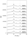
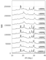
- 1 is an X-ray diffraction pattern of a crystalline sulfide solid electrolyte obtained in an example.
- 1 is an X-ray diffraction pattern of a crystalline sulfide solid electrolyte obtained in an example.
- 1 is an X-ray diffraction pattern of a crystalline sulfide solid electrolyte obtained in an example.
- 1 is an X-ray diffraction pattern of a crystalline sulfide solid electrolyte obtained in an example.
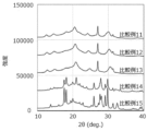
- 1 is an X-ray diffraction pattern of a crystalline sulfide solid electrolyte obtained in a comparative example.
- 1 is an X-ray diffraction pattern of a crystalline sulfide solid electrolyte obtained in a comparative example.
- 1 is a solid-state 31 P-NMR spectrum of a crystalline sulfide solid electrolyte obtained in an example.
- the present embodiment The following describes an embodiment of the present invention (hereinafter, may be referred to as “the present embodiment”). Note that in this specification, the upper and lower limit values of the numerical ranges “greater than or equal to,” “less than or equal to,” and “to” can be arbitrarily combined, and the numerical values in the examples can also be used as the upper and lower limit values.
- the solid electrolyte disclosed in Patent Document 1 contains lithium (Li), phosphorus (P), sulfur (S), oxygen (O), and halogen elements, and the inclusion of oxygen improves hydrolysis resistance, i.e., inhibits the generation of hydrogen sulfide, while the inclusion of halogen elements improves ionic conductivity.
- the ionic conductivity is 0.21 to 2.2 mS/cm, which is not high considering the large amount of raw materials containing halogen elements used.
- Raw materials containing halogen elements are expensive among the raw materials for solid electrolytes, so the solid electrolyte disclosed in Patent Document 1 has room for improvement in terms of reducing raw material costs.
- the solid electrolyte glass disclosed in Patent Document 2 is a solid electrolyte glass represented by the above composition formula (1') that contains alkali metals such as lithium, phosphorus, sulfur, halogens, and oxygen, as well as metal elements such as B, Al, and Si.
- Patent Document 2 also describes a glass ceramic obtained by heat-treating the solid electrolyte glass, but the ionic conductivity is 0.80 to 2.2 mS/cm, which is not high considering the large amount of raw materials containing halogens used. Therefore, like the solid electrolyte disclosed in Patent Document 1, there is room for improvement in terms of reducing raw material costs.
- Patent Document 3 contains LiI and oxygen, and while the inclusion of LiI improves ionic conductivity, it also reduces chemical stability, but oxygen suppresses the reduction in chemical stability.
- Paragraph [0010] of Patent Document 3 states that the material is highly amorphous to the extent that it has a glass transition point, so that Li ion conductivity can be increased, and the examples disclose an amorphous material that exhibits a halo pattern by X-ray diffraction (XRD) measurement, which is different from crystalline sulfide solid electrolytes.
- XRD X-ray diffraction
- the ionic conductivity is 0.6 to 1.2 mS/cm, which is not high considering the amount of raw material containing halogen elements used. Therefore, like the solid electrolyte disclosed in Patent Document 1, there is room for improvement in terms of reducing raw material costs and improving ionic conductivity.
- Patent Documents 1 to 3 focus on improving ionic conductivity and hydrolysis resistance, but none of them can be said to have high ionic conductivity considering the amount of raw materials containing halogen elements used. Furthermore, Patent Documents 1 to 3 attempt to improve ionic conductivity by using halogen elements, but such a method is known as technical common sense without even needing to mention these patent documents. Considering these, Patent Documents 1 to 3 do not provide any motivation to reduce the amount of halogen elements used in order to improve ionic conductivity. Furthermore, these patent documents do not disclose any idea of obtaining high ionic conductivity while reducing raw material costs by adding oxygen atoms to a sulfide solid electrolyte. Thus, it cannot be said that the conventional techniques of Patent Documents 1 to 3 and the like have produced a crystalline sulfide solid electrolyte with high ionic conductivity while reducing raw material costs.
- compositions required to obtain crystal structures that exhibit high ionic conductivity such as the thiolicon region II crystal structure and the LGPS crystal structure obtained in the examples described below, were limited to a very small number of compositions. Furthermore, as shown in the comparative examples described below, simply reducing the amount of halogen atoms used without including oxygen atoms does not result in these crystal structures and reduces ionic conductivity.
- the inventors focused on replacing some of the sulfur atoms in a sulfide solid electrolyte with oxygen atoms. As a result of further development, they discovered that a material containing lithium atoms, phosphorus atoms, sulfur atoms, oxygen atoms, and halogen atoms and expressed by a specific composition formula can have high ionic conductivity while reducing raw material costs.
- Patent Documents 1 to 3 do not pay any attention to the fact that high ionic conductivity can be achieved and raw material costs can be reduced by making a composition represented by a specific composition formula in addition to replacing some of the sulfur atoms with oxygen atoms, and in particular, they do not pay any attention to the reduction in raw material costs by incorporating oxygen atoms as a substitute for sulfur atoms.
- a composition represented by a specific composition formula in addition to replacing some of the sulfur atoms with oxygen atoms, and in particular, they do not pay any attention to the reduction in raw material costs by incorporating oxygen atoms as a substitute for sulfur atoms.
- solid electrolyte refers to an electrolyte that maintains a solid state at 25°C under a nitrogen atmosphere.
- the “sulfide solid electrolyte” of this embodiment is a solid electrolyte that contains oxygen atoms in addition to lithium atoms, sulfur atoms, phosphorus atoms, and halogen atoms, and has ionic conductivity due to lithium atoms.
- sulfide solid electrolyte includes both crystalline sulfide solid electrolytes having a crystal structure and amorphous sulfide solid electrolytes.
- a crystalline sulfide solid electrolyte is a solid electrolyte in which a peak derived from a solid electrolyte is observed in the X-ray diffraction pattern in a powder X-ray diffraction (XRD) measurement, and is a material in which the presence or absence of a peak derived from the raw material of the solid electrolyte is not important.
- a crystalline sulfide solid electrolyte includes a crystal structure derived from a solid electrolyte, and may be a crystal structure derived from the solid electrolyte in part or entirely. And, as long as the crystalline sulfide solid electrolyte has the above-mentioned X-ray diffraction pattern, it may include an amorphous sulfide solid electrolyte (also called a "glass component") in part. Therefore, the crystalline sulfide solid electrolyte includes so-called glass ceramics obtained by heating an amorphous solid electrolyte (glass component) to a temperature above the crystallization temperature.
- amorphous sulfide solid electrolyte refers to a solid electrolyte having an X-ray diffraction pattern that is a halo pattern in which no peaks other than those derived from the material are observed in a powder X-ray diffraction (XRD) measurement, regardless of whether or not there are peaks derived from the raw materials of the solid electrolyte.
- XRD powder X-ray diffraction
- the sulfide solid electrolyte according to the first embodiment of the present invention is A crystalline sulfide solid electrolyte containing lithium atoms, phosphorus atoms, sulfur atoms, oxygen atoms, and halogen atoms and having a composition represented by the following composition formula (1): It is. (100-y) (0.5) (Li 3+2z P(S 1-x O x ) 4+z )+(y)LiX (1) (In the composition formula (1), x, y, and z each satisfy 0.00060 ⁇ x ⁇ 0.25, 0.50 ⁇ y ⁇ 14.0, and ⁇ 0.17 ⁇ z ⁇ 1.5. X represents a halogen atom.)
- the crystalline sulfide solid electrolyte of this embodiment contains lithium atoms, phosphorus atoms, sulfur atoms, oxygen atoms, and halogen atoms as described above, and has a composition represented by the above-mentioned predetermined composition formula, so that it has high ionic conductivity while being low cost.
- having high ionic conductivity it is known that the use of lithium halide can improve ionic conductivity as described above.
- lithium halide is expensive, and reducing its usage leads to reduced raw material costs, but usually leads to a decrease in ionic conductivity. In other words, reduced raw material costs and high ionic conductivity are in a trade-off relationship.
- the crystalline sulfide solid electrolyte of this embodiment has a composition represented by the above-mentioned predetermined composition formula, but some of the sulfur atoms are replaced with oxygen atoms, thereby enabling a reduction in raw material costs.
- the electrolyte can have high ionic conductivity by having a composition represented by the above-mentioned composition formula. In this way, the crystalline sulfide solid electrolyte of this embodiment can simultaneously achieve reduced raw material costs and high ionic conductivity.
- the crystalline sulfide solid electrolyte according to the second aspect of the present embodiment is the same as the first aspect, In the composition formula (1), the product of x and y (x ⁇ y) is 0.0050 or more and 2.7 or less. That is it.
- x and y can each be any value selected from the above range, but if the product of x and y is within the above range, it will be a well-balanced value, making it easier to simultaneously achieve reduced raw material costs and high ionic conductivity. More specifically, it is considered as follows. As described below, x means the substitution rate of oxygen atoms when replacing some of the sulfur atoms with oxygen atoms, and y means the content of halogen atoms, so that if the product is within the above range, it means that the amount of oxygen atoms and the amount of halogen atoms can be balanced.
- the crystal lattice size can be reduced, and by further containing the amount of oxygen atoms and the amount of halogen atoms in a balanced manner, it is possible to stabilize crystal structures with high ionic conductivity, such as a thiolicon region II type crystal structure and a LGPS type crystal structure. Therefore, it is thought that the content of halogen atoms, which has been considered necessary for stabilizing these crystal structures that can exhibit high ionic conductivity, can be reduced, that is, it is easier to simultaneously achieve reduced raw material costs and high ionic conductivity.
- the crystalline sulfide solid electrolyte according to the third aspect of the present embodiment is the first or second aspect described above, A peak due to PSO 3 3- was observed at 39.6 ⁇ 5.0 ppm by solid-state 31 P-NMR measurement.
- the crystalline sulfide solid electrolyte according to a fourth embodiment is any one of the first to third embodiments, A peak due to PO 4 3- was observed at 9.2 ⁇ 5.0 ppm by solid-state 31 P-NMR measurement.
- the crystalline sulfide solid electrolyte according to the fifth aspect is any one of the first to fourth aspects described above, A peak due to PS 2 O 2 3- was observed at 70.3 ⁇ 5.0 ppm by solid-state 31 P-NMR measurement. That is it.
- the crystalline sulfide solid electrolyte of this embodiment is likely to have high ionic conductivity while being low cost.
- the crystalline sulfide solid electrolyte according to the sixth aspect of the present embodiment is any one of the first to fifth aspects described above, At least two exothermic peaks are measured in a thermogravimetric differential calorimetry (measured at a heating rate of 10° C./min), and the temperature difference between the peak tops of the two exothermic peaks is 20° C. or more and 110° C. or less. That is it.
- thermogravimetric differential thermal analysis If the above two exothermic peaks are observed in thermogravimetric differential thermal analysis, the crystalline sulfide solid electrolyte of this embodiment is likely to be low-cost and have high ionic conductivity.
- the crystalline sulfide solid electrolyte according to the seventh aspect of the present embodiment is any one of the first to sixth aspects described above,
- the halogen atom is at least one halogen atom selected from a chlorine atom, a bromine atom, and an iodine atom.
- the crystalline sulfide solid electrolyte according to the eighth aspect is any one of the first to seventh aspects,
- the halogen atoms are bromine and iodine atoms. That is it.
- halogen atom selected from chlorine, bromine and iodine atoms as the halogen atom, that is, a chlorine atom, a bromine atom or an iodine atom alone or two or more halogen atoms selected from these atoms, it becomes easier to obtain a higher ionic conductivity.
- halogen atom selected from chlorine, bromine and iodine atoms that is, a chlorine atom, a bromine atom or an iodine atom alone or two or more halogen atoms selected from these atoms.
- bromine and iodine atoms simultaneously, it becomes easier to obtain a particularly high ionic conductivity.
- the crystalline sulfide solid electrolyte according to a ninth aspect of the present embodiment is any one of the first to eighth aspects described above,
- the ionic conductivity is 0.70 mS/cm or more.
- the crystalline sulfide solid electrolyte according to the tenth aspect is any one of the first to ninth aspects,
- the ionic conductivity is 2.5 mS/cm or more. That is it.
- the crystalline sulfide solid electrolyte of this embodiment contains lithium atoms, phosphorus atoms, sulfur atoms, oxygen atoms, and halogen atoms, and has a composition represented by a specific composition formula, so that the ionic conductivity is high and falls within the above range.
- a crystalline sulfide solid electrolyte according to an eleventh aspect of the present embodiment is any one of the first to tenth aspects described above, does not contain at least one metal atom selected from sodium atoms, boron atoms, aluminum atoms, silicon atoms, germanium atoms, arsenic atoms, selenium atoms, antimony atoms, tellurium atoms, lead atoms, and bismuth atoms; That is it.
- the crystalline sulfide solid electrolyte of this embodiment does not contain the above metal atoms, and therefore contains less impurities, making it easier for the crystalline sulfide solid electrolyte of this embodiment to have high ionic conductivity while being low cost.
- a crystalline sulfide solid electrolyte according to a twelfth aspect of the present embodiment is any one of the first to eleventh aspects,
- the oxygen atom is derived from P2O5 ; That is it.
- the crystalline sulfide solid electrolyte of the present embodiment is produced, by using P 2 O 5 as a raw material, some of the sulfur atoms can be easily replaced with oxygen atoms, and oxygen atoms can be easily incorporated into the structure of the solid electrolyte. As a result, the crystalline sulfide solid electrolyte of the present embodiment is likely to have high ionic conductivity while being low cost.
- a crystalline sulfide solid electrolyte according to a thirteenth aspect of the present embodiment is any one of the first to twelfth aspects, It is a glass ceramic, That is it.
- glass ceramics are obtained by heating an amorphous solid electrolyte (glass component) above its crystallization temperature.
- the crystalline sulfide solid electrolyte obtained in this way is low-cost and tends to have high ionic conductivity.
- the crystalline sulfide solid electrolyte of this embodiment is A crystalline sulfide solid electrolyte containing lithium atoms, phosphorus atoms, sulfur atoms, oxygen atoms, and halogen atoms and having a composition represented by the following composition formula (1): It is. (100-y) (0.5) (Li 3+2z P(S 1-x O x ) 4+z )+(y)LiX (1) (In the composition formula (1), x, y, and z satisfy 0.00060 ⁇ x ⁇ 0.25, 0.50 ⁇ y ⁇ 14.0, and ⁇ 0.17 ⁇ z ⁇ 1.5. , X represents a halogen atom.
- the crystalline sulfide solid electrolyte of the present embodiment contains lithium atoms, phosphorus atoms, sulfur atoms, oxygen atoms, and halogen atoms.
- halogen atoms include fluorine, chlorine, bromine and iodine atoms.
- chlorine, bromine and iodine atoms are preferred, and bromine and iodine atoms are preferred.
- the halogen atoms may include these atoms alone or multiple types of atoms.
- the oxygen atoms in the crystalline sulfide solid electrolyte of this embodiment are preferably derived from P 2 O 5.
- the method for producing the crystalline sulfide solid electrolyte of this embodiment is not particularly limited as long as it contains lithium atoms, phosphorus atoms, sulfur atoms, oxygen atoms, and halogen atoms and has a composition represented by the above composition formula.
- the crystalline sulfide solid electrolyte of the present embodiment preferably does not contain at least one metal atom selected from sodium atoms, boron atoms, aluminum atoms, silicon atoms, germanium atoms, arsenic atoms, selenium atoms, antimony atoms, tellurium atoms, lead atoms, and bismuth atoms.
- the crystalline sulfide solid electrolyte of the present embodiment is likely to have high ionic conductivity at low cost.
- not containing metal atoms literally means not containing any metal atoms at all (i.e., 0 mass%), but also includes cases where metal atoms are unavoidably mixed in.
- the content is 3 mass% or less, 2 mass% or less, 1 mass%, 0.5 mass% or less, 0.3 mass% or less, or 0.1 mass% or less based on the total amount of the crystalline sulfide solid electrolyte.
- the crystalline sulfide solid electrolyte of this embodiment contains lithium atoms, phosphorus atoms, sulfur atoms, oxygen atoms, and halogen atoms, and has a composition represented by the following composition formula (1).
- the composition represented by the following composition formula (1) high ionic conductivity can be obtained at low cost.
- the type and composition of the atoms constituting the crystalline sulfide solid electrolyte of this embodiment can be confirmed, for example, by an ICP emission spectrometer.
- x, y, and z each satisfy 0.00060 ⁇ x ⁇ 0.25, 0.50 ⁇ y ⁇ 14.0, and ⁇ 0.17 ⁇ z ⁇ 1.5.
- X represents a halogen atom.
- x means the substitution rate of oxygen atoms when some of the sulfur atoms are replaced with oxygen atoms. From the viewpoint of satisfying 0.00060 ⁇ x ⁇ 0.25 and obtaining high ionic conductivity at low cost, x is preferably 0.0010 or more, more preferably 0.0050 or more, even more preferably 0.010 or more, still more preferably 0.011 or more, and particularly preferably 0.012 or more, and the upper limit is preferably 0.20 or less, more preferably 0.15 or less, even more preferably 0.11 or less, and still more preferably 0.080 or less.
- Representative numerical ranges for x are 0.00060 or more and 0.20 or less, 0.00060 or more and 0.15 or less, 0.00060 or more and 0.11 or less, 0.00060 or more and 0.080 or less, 0.0010 or more and 0.20 or less, 0.0010 or more and 0.15 or less, 0.0010 or more and 0.11 or less, 0.0010 or more and 0.080 or less, 0.0050 or more and 0.20 or less, 0.0050 or more and 0.15 or less, 0.0050 or more and 0.11 or less, 0.0050 or more and 0.080 or less, 0.010 or more and 0 .25 or less, 0.010 to 0.20 or less, 0.010 to 0.15 or less, 0.010 to 0.11 or less, 0.010 to 0.080 or less, 0.011 to 0.25 or less, 0.011 to 0.20 or less, 0.011 to 0.15 or less, 0.011 to 0.11 or less, 0.011 to 0.080 or less, 0.012 to 0.25 or less, 0.012 to 0.
- composition formula (1) means the content of halogen atoms.
- the composition formula (1) is expressed in the form of LiX (lithium halide), but the raw material containing halogen atoms is not limited to lithium halide, and may be, for example, an elemental halogen, as described later.
- y satisfies 0.50 ⁇ y ⁇ 14.0, and from the viewpoint of obtaining high ionic conductivity at low cost, is preferably 1.0 or more, more preferably 1.5 or more, even more preferably 3.0 or more, even more preferably 7.0 or more, particularly preferably 8.0 or more, and even more particularly preferably 9.0 or more, and the upper limit is preferably 13.5 or less, more preferably 13.0 or less, even more preferably 12.7 or less, and even more preferably 12.0 or less.
- Representative numerical ranges for y are 0.50 or more and 14.0 or less, 0.50 or more and 13.5 or less, 0.50 or more and 13.0 or less, 0.50 or more and 12.7 or less, 0.50 or more and 12.0 or less, 1.0 or more and 14.0 or less, 1.0 or more and 13.5 or less, 1.0 or more and 13.0 or less, 1.0 or more and 12.7 or less, 1.0 or more and 12.0 or less, 1.5 or more and 14.0 or less, 1.5 or more and 13.5 or less, 1.5 or more and 13.0 or less, 1.5 or more and 12.7 or less, 1.5 or more and 12.0 or less, 3.0 or more and 14.0 or less, 3.0 or more and 13.5 or less , 3.0 or more and 13.0 or less, 3.0 or more and 12.7 or less, 3.0 or more and 12.0 or less, 7.0 or more and 14.0 or less, 7.0 or more and 13.5 or less, 7.0 or more and 13.0 or less, 7.0 or more and 12.7 or less, 7.0 or more and 12.0 or less,
- the value z indicates the deviation of the ratio of lithium atoms to sulfur atoms from the Li 3 PS 4 structure which is the basic skeleton of the thiolicon region II type crystal structure and the LGPS type crystal structure.
- z is preferably ⁇ 0.15 or more, more preferably ⁇ 0.11 or more, even more preferably ⁇ 0.080 or more, still more preferably ⁇ 0.040 or more, and particularly preferably ⁇ 0.020 or more, and the upper limit is preferably 1.0 or less, more preferably 0.90 or less, even more preferably 0.60 or less, still more preferably 0.40 or less, and particularly preferably 0.20 or less.
- Representative numerical ranges for z are -0.17 or more and 1.5 or less, -0.17 or more and 1.0 or less, -0.17 or more and 0.90 or less, -0.17 or more and 0.60 or less, -0.17 or more and 0.40 or less, -0.17 or more and 0.20 or less, -0.15 or more and 1.5 or less, -0.15 or more and 1.0 or less, -0.15 or more and 0.90 or less, -0.15 or more and 0.60 or less, -0.15 or more and 0.40 or less, -0.15 or more and 0.20 or less, -0.11 or more and 1.5 or less, -0.11 or more and 1.0 or less, -0.11 or more and 0.90 or less, -0.11 or more and 0.60 or less, -0.11 or more and 0.40 or less, -0.11 or more and 0.20 or less, -0.0 Preferred examples include 80 or more and 1.5 or less, -0.080 or more and 1.0 or less, -0.080 or more
- the product of x and y (x x y) is preferably 0.0050 or more, more preferably 0.010 or more, even more preferably 0.025 or more, even more preferably 0.050 or more, particularly preferably 0.075 or more, and even more preferably 0.10 or more, and the upper limit is preferably 2.7 or less, more preferably 2.0 or less, even more preferably 1.25 or less, even more preferably 0.60 or less, particularly preferably 0.45 or less, and even more preferably 0.28 or less.
- x and y can each take any value selected from the above range, but by adopting x and y such that the product of x and y (x x y) falls within the above range, the above x and y will take a balanced value, making it easier to obtain high ionic conductivity at low cost.
- the representative numerical ranges of the product of x and y (x ⁇ y) are 0.0050 or more and 2.7 or less, 0.0050 or more and 2.0 or less, 0.0050 or more and 1.25 or less, 0.0050 or more and 0.60 or less, 0.0050 or more and 0.45 or less, 0.0050 or more and 0.28 or less, 0.010 or more and 2.7 or less, 0.010 or more and 2.0 or less, 0.010 or more and 1.25 or less, 0.010 or more and 0.60 or less, 0.010 or more and 0.45 or less, 0.010 or more and 0.28 or less, 0.025 or more and 2.7 or less, 0.025 or more and 2.0 or less, 0.025 or more and 1.25 or less, 0.025 or more and 0.60 or less, 0.025 or more and 0.45 or less Preferred examples include 0.025 to 0.28, 0.050 to 2.7, 0.050 to 2.0, 0.050 to 1.25, 0.050 to 0.60, 0.050 to 0.45, 0.0 0.0
- X represents a halogen atom.
- the halogen atom is the same as the halogen atom described as the constituent atom of the crystalline sulfide solid electrolyte of this embodiment.
- the crystalline sulfide solid electrolyte of this embodiment is preferably one in which a peak due to PSO 3 3- is observed at 39.6 ⁇ 5.0 ppm by solid-state 31 P-NMR measurement. It is also preferable that a peak due to PO 4 3- is observed at 9.2 ⁇ 5.0 ppm, and further a peak due to PS 2 O 2 3- is observed at 70.3 ⁇ 5.0 ppm.
- the measurement method of solid-state 31 P-NMR measurement in this specification will be described in the examples.
- the peak by solid-state 31 P-NMR measurement may be within the range of ⁇ 5.0 ppm, and further within the range of ⁇ 4.0 ppm, ⁇ 3.0 ppm, and ⁇ 2.0 ppm.
- the peaks due to PSO 3 3- , PO 4 3- , and PS 2 O 2 3- indicate that at least the crystalline sulfide solid electrolyte of this embodiment has oxygen atoms in its structure.
- a crystalline sulfide solid electrolyte having the above peaks in the solid-state 31 P-NMR spectrum has oxygen atoms incorporated into its structure, i.e., some of the sulfur atoms are replaced with oxygen atoms, and therefore has high ionic conductivity at low cost.
- thermogravimetric differential calorimetry measured at a heating rate of 10° C./min
- the temperature difference between the peak tops of the two exothermic peaks is 20° C. or more and 110° C. or less.
- the crystalline sulfide solid electrolyte of this embodiment has oxygen atoms incorporated into its structure, i.e., some of the sulfur atoms are replaced with oxygen atoms, and therefore has high ionic conductivity at low cost.
- the lower limit of the temperature difference is preferably 30°C or more, more preferably 35°C or more, even more preferably 40°C or more, and even more preferably 50°C or more
- the upper limit is preferably 100°C or less, more preferably 95°C or less, even more preferably 90°C or less, and even more preferably 75°C or less.
- the temperature (Tc1) of the peak top of the exothermic peak on the low temperature side is preferably 180°C or higher, more preferably 190°C or higher, even more preferably 200°C or higher, and even more preferably 210°C or higher, with the upper limit being preferably 300°C or lower, more preferably 290°C or lower, and even more preferably 280°C or lower.
- the temperature (Tc2) of the peak top of the exothermic peak on the high temperature side is preferably 200°C or higher, more preferably 220°C or higher, even more preferably 240°C or higher, and even more preferably 260°C or higher.
- the ionic conductivity of the crystalline sulfide solid electrolyte of this embodiment can be 0.70 mS / cm or more, further 0.73 mS / cm or more, 0.75 mS / cm or more, 0.80 mS / cm or more, 0.85 mS / cm or more, 0.95 mS / cm or more, 1.0 mS / cm or more, 1.50 mS / cm or more, 2.0 mS / cm or more, or 2.5 mS / cm or more.
- the crystalline sulfide solid electrolyte of the present embodiment has high ionic conductivity, and when the amount of raw material containing halogen atoms used is small, more specifically, when y in the above composition formula (1) is as small as 10.0 or less, the above ionic conductivity can be achieved.
- the peak position of the diffraction peak of the crystalline sulfide solid electrolyte of this embodiment may vary depending on the peak position, but may be within the range of ⁇ 0.6 °, ⁇ 0.7 °, or even ⁇ 0.5 °.
- the measurement method of X-ray diffraction measurement using CuK ⁇ radiation in this specification will be described in the examples.
- the crystalline sulfide solid electrolyte of this embodiment preferably has at least one of the thiolicon region II type crystal structure and the LGPS type crystal structure.
- the crystalline sulfide solid electrolyte of this embodiment has a composition represented by the above-mentioned predetermined composition formula, and has a low content of halogen atoms, ie, y is 0.50 ⁇ y ⁇ 14.0, but by containing oxygen atoms, it is likely to have a crystal structure that exhibits these high ionic conductivity.
- the crystalline sulfide solid electrolyte of this embodiment has high ionic conductivity while achieving a reduction in raw material costs by reducing the content of halogen atoms.
- the crystalline sulfide solid electrolyte of this embodiment mainly has a thiolicon region II type crystal structure, mainly has a LGPS type crystal structure, and these crystal structures are mixed.
- mainly having a thiolicon region II type crystal structure means that at least one of the above diffraction peaks attributable to the thiolicon region II type crystal structure can be confirmed
- mainly having an LGPS type crystal structure means that at least one of the above diffraction peaks attributable to the LGPS type crystal structure can be confirmed
- mixed means that both diffraction peaks can be confirmed, or that some of the both diffraction peaks overlap and cannot be separated.
- the certain crystal structure is mainly present, and if it is in between, i.e., more than 40% but less than 60%, it can be considered that the certain crystal structure is mixed.
- the term "mainly” can also be determined by the intensity of a certain diffraction peak when the thiolisicon region II type crystal structure and the LGPS type crystal structure coexist.
- Examples of the thio-LISICON region II type crystal structure include Li4 - xGe1 -xPxS4- based thio -LISICON region II type crystal structure (see Kanno et al., Journal of the Electrochemical Society, 148(7)A742-746(2001)), and crystal structures similar to Li4 -xGe1 -xPxS4 - based thio-LISICON region II type (see Solid State Ionics, 177(2006), 2721-2725).
- the LGPS type crystal structure may be a crystal structure having a composition represented by Li3 + xPS4 -yOy (wherein x satisfies -1 ⁇ x ⁇ 1 and y satisfies 0 ⁇ y ⁇ 4) (also referred to as "Li-P-S-O based sulfide solid electrolyte").
- the notation of the crystal structure as "Li 4-x Ge 1-x P x S 4 thio-LISICON Region II type” means that it was found in the above document as a crystal structure composed of Li, Ge, P and S atoms. Since the sulfide solid electrolyte obtained by the manufacturing method of this embodiment contains lithium atoms, phosphorus atoms, sulfur atoms and halogen atoms, it may not be represented by the composition formula of "Li 4-x Ge 1-x P x S 4 " in "Li 4-x Ge 1-x P x S 4 thio-LISICON Region II type".
- the sulfide solid electrolyte obtained by the manufacturing method of this embodiment has the same diffraction peak as the above-mentioned "thiolicon region II type crystal structure" (including the above-mentioned “similar crystal structure"), it can be said that the sulfide solid electrolyte has a thiolicon region II type crystal structure formed by lithium atoms, phosphorus atoms, sulfur atoms and halogen atoms. This is not limited to the thiolicon region II type crystal structure, but is also the same for the LGPS type crystal structure.
- these peaks are expressed, resulting in higher ionic conductivity.
- the positions of these diffraction peaks vary within the ranges of ⁇ 0.7°, ⁇ 0.6°, and ⁇ 0.5°.
- the thiolicon region II type crystal structure and the LGPS type crystal structure preferably possessed by the crystalline sulfide solid electrolyte of the present embodiment can be formed without using an amorphous solid electrolyte (glass component), or can be formed as a so-called glass ceramic obtained by heating an amorphous solid electrolyte (glass component) to a crystallization temperature or higher.
- the crystalline sulfide solid electrolyte of the present embodiment is preferably a glass ceramic.
- the crystalline sulfide solid electrolyte of the present embodiment is low cost and has high ionic conductivity, and has excellent battery performance. Therefore, for example, it is preferably used in combination with an electrode active material as an electrode mixture or in a lithium ion battery.
- the sulfide solid electrolyte of this embodiment When used in a lithium ion battery, it may be used in the positive electrode layer, the negative electrode layer, or the electrolyte layer. When used in a positive electrode layer, it can be used as an electrode mixture containing the crystalline sulfide solid electrolyte of this embodiment and a positive electrode active material, and when used in a negative electrode layer, it can be used as an electrode mixture containing the crystalline sulfide solid electrolyte of this embodiment and a negative electrode active material. In addition, the crystalline sulfide solid electrolyte may be used as it is in the electrolyte layer.
- the electrode mixture contains the crystalline sulfide solid electrolyte of the present embodiment and an electrode active material.
- the electrode active material a positive electrode active material or a negative electrode active material is adopted depending on whether the electrode mixture is used for a positive electrode or a negative electrode.
- the positive electrode active material can be any material that can promote a battery chemical reaction involving the movement of lithium ions resulting from atoms that are used to exhibit ionic conductivity in relation to the negative electrode active material, preferably lithium atoms, and is not particularly limited.
- positive electrode active materials that can insert and remove lithium ions include oxide-based positive electrode active materials and sulfide-based positive electrode active materials.
- LMO lithium manganese oxide
- LCO lithium cobalt oxide
- NMC lithium nickel manganese cobalt oxide
- NCA lithium nickel cobalt aluminate
- LNCO lithium nickel cobalt oxide
- sulfide-based positive electrode active materials include titanium sulfide (TiS 2 ), molybdenum sulfide (MoS 2 ), iron sulfide (FeS, FeS 2 ), copper sulfide (CuS), and nickel sulfide (Ni 3 S 2 ).
- TiS 2 titanium sulfide
- MoS 2 molybdenum sulfide
- FeS, FeS 2 iron sulfide
- CuS copper sulfide
- Ni 3 S 2 nickel sulfide
- the positive electrode active material may be used alone or in combination of two or more kinds.
- the negative electrode active material can be used without any particular limitation as long as it can promote a battery chemical reaction accompanied by the movement of lithium ions caused by lithium atoms, such as an atom that is used as an atom that exhibits ion conductivity, preferably a metal that can form an alloy with lithium atoms, an oxide thereof, an alloy of the metal with lithium atoms, etc.
- a negative electrode active material capable of inserting and removing lithium ions any material known as a negative electrode active material in the battery field can be used without any limitation.
- Examples of such negative electrode active materials that can be used in the case of constituting a lithium ion battery include silicon-based active materials such as Si, Si alloys, and silicon oxide; carbon-based active materials such as graphite and hard carbon; various oxide-based active materials such as lithium titanate; metals that can form metal lithium or alloys with metal lithium, such as metal lithium, indium metal, aluminum metal, silicon metal, and tin metal, oxides of these metals, and alloys of these metals with metal lithium.
- the electrode active material may have a coating layer on its surface.
- Materials for forming the coating layer include ion conductors such as nitrides, oxides, and composites of atoms, preferably lithium atoms, that exhibit ion conductivity in the sulfide solid electrolyte.
- conductors having a lysicone-type crystal structure such as Li 4-2x Zn x GeO 4 , which has a main structure of lithium nitride (Li 3 N) and Li 4 GeO 4
- conductors having a thiolysicone-type crystal structure such as Li 4-x Ge 1-x P x S 4, which has a Li 3 PO 4 type skeleton structure
- conductors having a perovskite-type crystal structure such as La 2/3-x Li 3x TiO 3
- conductors having a NASICON-type crystal structure such as LiTi 2 (PO 4 ) 3 .
- lithium titanates such as Li y Ti 3-y O 4 (0 ⁇ y ⁇ 3) and Li 4 Ti 5 O 12 (LTO)
- lithium metal oxides of metals belonging to Group 5 of the periodic table such as LiNbO 3 and LiTaO 3
- oxide-based conductors such as Li 2 O—B 2 O 3 —P 2 O 5 , Li 2 O—B 2 O 3 —ZnO, and Li 2 O—Al 2 O 3 —SiO 2 —P 2 O 5 —TiO 2 .
- An electrode active material having a coating layer can be obtained, for example, by applying a solution containing various atoms constituting the material forming the coating layer to the surface of an electrode active material, and then baking the electrode active material after application at a temperature of preferably 200° C. or higher and 400° C. or lower.
- the solution containing various atoms may be a solution containing alkoxides of various metals such as lithium ethoxide, titanium isopropoxide, niobium isopropoxide, tantalum isopropoxide, etc.
- the solvent may be an alcohol solvent such as ethanol or butanol, an aliphatic hydrocarbon solvent such as hexane, heptane, or octane, or an aromatic hydrocarbon solvent such as benzene, toluene, or xylene.
- the above attachment may be performed by immersion, spray coating, or the like.
- the firing temperature is preferably 200°C or higher and 400°C or lower, and more preferably 250°C or higher and 390°C or lower, and the firing time is usually about 1 minute to 10 hours, and preferably 10 minutes to 4 hours.
- the coverage of the coating layer is preferably 90% or more, more preferably 95% or more, and even more preferably 100% based on the surface area of the electrode active material, that is, the entire surface is preferably covered.
- the thickness of the coating layer is preferably 1 nm or more, more preferably 2 nm or more, and the upper limit is preferably 30 nm or less, more preferably 25 nm or less.
- the thickness of the coating layer can be measured by cross-sectional observation using a transmission electron microscope (TEM), and the coverage rate can be calculated from the thickness of the coating layer, the elemental analysis value, and the BET specific surface area.
- TEM transmission electron microscope
- the electrode mixture may contain other components such as a conductive material, a binder, etc., in addition to the crystalline sulfide solid electrolyte and electrode active material of the present embodiment. That is, the electrode mixture may contain other components such as a conductive material, a binder, etc., in addition to the crystalline sulfide solid electrolyte and electrode active material of the present embodiment. The other components such as a conductive material and a binder may be further added and mixed with the crystalline sulfide solid electrolyte and the electrode active material when the crystalline sulfide solid electrolyte and the electrode active material are mixed together.
- Examples of the conductive material from the viewpoint of improving battery performance by improving electronic conductivity, include carbon-based materials such as artificial graphite, graphite carbon fiber, resin-calcined carbon, pyrolytic vapor-grown carbon, coke, mesocarbon microbeads, furfuryl alcohol resin-calcined carbon, polyacene, pitch-based carbon fiber, vapor-grown carbon fiber, natural graphite, and non-graphitizable carbon.
- carbon-based materials such as artificial graphite, graphite carbon fiber, resin-calcined carbon, pyrolytic vapor-grown carbon, coke, mesocarbon microbeads, furfuryl alcohol resin-calcined carbon, polyacene, pitch-based carbon fiber, vapor-grown carbon fiber, natural graphite, and non-graphitizable carbon.
- the binder is not particularly limited as long as it can impart functions such as binding property and flexibility, and examples thereof include fluorine-based polymers such as polytetrafluoroethylene and polyvinylidene fluoride, thermoplastic elastomers such as butylene rubber and styrene-butadiene rubber, and various resins such as acrylic resins, acrylic polyol resins, polyvinyl acetal resins, polyvinyl butyral resins, and silicone resins.
- fluorine-based polymers such as polytetrafluoroethylene and polyvinylidene fluoride
- thermoplastic elastomers such as butylene rubber and styrene-butadiene rubber
- various resins such as acrylic resins, acrylic polyol resins, polyvinyl acetal resins, polyvinyl butyral resins, and silicone resins.
- the compounding ratio (mass ratio) of the electrode active material to the crystalline sulfide solid electrolyte in the electrode mixture is preferably 99.5:0.5 to 40:60, more preferably 99:1 to 50:50, and even more preferably 98:2 to 60:40, in order to improve battery performance and take into consideration manufacturing efficiency.
- the content of the conductive material in the electrode mixture is not particularly limited, but in consideration of improving battery performance and production efficiency, the content is preferably 0.5 mass% or more, more preferably 1 mass% or more, and even more preferably 1.5 mass% or more, and the upper limit is preferably 10 mass% or less, preferably 8 mass% or less, and even more preferably 5 mass% or less.
- the content of the binder in the electrode mixture is not particularly limited, but in consideration of improving battery performance and production efficiency, the content is preferably 1 mass % or more, more preferably 3 mass % or more, and even more preferably 5 mass % or more, and the upper limit is preferably 20 mass % or less, preferably 15 mass % or less, and even more preferably 10 mass % or less.
- the crystalline sulfide solid electrolyte of the present embodiment can also be used in a lithium ion battery as described above.
- the lithium ion battery can include at least one selected from the sulfide solid electrolyte of the present embodiment and the electrode mixture.
- the lithium ion battery there are no particular limitations on the configuration of the lithium ion battery, so long as it contains the crystalline sulfide solid electrolyte of the present embodiment described above and an electrode composite material containing the same, and it may have the configuration of a commonly used lithium ion battery.
- the lithium ion battery preferably includes, for example, a positive electrode layer, a negative electrode layer, an electrolyte layer, and a current collector.
- the positive electrode layer and the negative electrode layer preferably use an electrode mixture containing the crystalline sulfide solid electrolyte of the present embodiment, and the electrolyte layer preferably uses the crystalline sulfide solid electrolyte of the present embodiment.
- the current collector may be any known material.
- a layer of a material that reacts with the solid electrolyte such as Au, Pt, Al, Ti, or Cu, coated with Au or the like can be used.
- the crystalline sulfide solid electrolyte of the present embodiment described above can be obtained by a production method including mixing raw material components including, for example, lithium atoms, sulfur atoms, phosphorus atoms, oxygen atoms, and halogen atoms.
- the raw material-containing material includes lithium atoms, phosphorus atoms, sulfur atoms, oxygen atoms, and halogen atoms. More specifically, the raw material-containing material includes a substance (hereinafter also referred to as "raw material") that includes one or more types of atoms selected from the group consisting of these atoms, and preferably includes two or more types of raw materials.
- the raw material include lithium sulfide; phosphorus sulfide such as diphosphorus trisulfide (P 2 S 3 ) and diphosphorus pentasulfide (P 2 S 5 ); and other raw materials containing at least two types of atoms selected from the above-mentioned atoms, as well as raw materials consisting of one type of atom selected from the above-mentioned atoms, such as elemental phosphorus and elemental sulfur.
- phosphorus sulfide such as diphosphorus trisulfide (P 2 S 3 ) and diphosphorus pentasulfide (P 2 S 5 )
- other raw materials containing at least two types of atoms selected from the above-mentioned atoms as well as raw materials consisting of one type of atom selected from the above-mentioned atoms, such as elemental phosphorus and elemental sulfur.
- lithium sulfide and phosphorus sulfides such as diphosphorus trisulfide (P 2 S 3 ) and diphosphorus pentasulfide (P 2 S 5 ) are preferred, and among the phosphorus sulfides, diphosphorus pentasulfide (P 2 S 5 ) is preferred.
- the raw material may preferably include a substance containing a halogen atom, for example, a lithium halide such as lithium fluoride, lithium chloride, lithium bromide, or lithium iodide; or an elemental halogen such as fluorine (F 2 ), chlorine (Cl 2 ), bromine (Br 2 ), or iodine (I 2 ).
- a lithium halide such as lithium fluoride, lithium chloride, lithium bromide, or lithium iodide
- an elemental halogen such as fluorine (F 2 ), chlorine (Cl 2 ), bromine (Br 2 ), or iodine (I 2 ).
- a substance containing oxygen atoms is also preferred.
- Representative examples include diphosphorus pentoxide (P 2 O 5 ), lithium oxide (Li 2 O), lithium hydroxide (LiOH), etc.
- diphosphorus pentoxide (P 2 O 5 ) is preferred in consideration of the ease of replacing some of the sulfur atoms in the structure of the crystalline sulfide solid electrolyte with oxygen atoms.
- the raw materials include substances containing at least one atom selected from the group consisting of lithium atoms, phosphorus atoms, sulfur atoms, oxygen atoms, and halogen atoms, such as phosphorus halides such as various phosphorus fluorides ( PF3 , PF5 ), various phosphorus chlorides ( PCl3 , PCl5 , P2Cl4 ), various phosphorus bromides ( PBr3 , PBr5 ), and various phosphorus iodides ( PI3 , P2I4 ); thiophosphoryl fluoride ( PSF3 ), thiophosphoryl chloride ( PSCl3 ), thiophosphoryl bromide ( PSBr3 ), thiophosphoryl iodide ( PSI3 ), thiophosphoryl fluoride dichloride ( PSCl2F ), thiophosphoryl fluoride dibromide ( PSBr2F ), and the like.
- phosphorus halides such
- thiophosphoryl halides such as thiophosphoryl halides F); lithium compounds such as lithium oxide, lithium hydroxide, and lithium carbonate; alkali metal sulfides such as sodium sulfide, potassium sulfide, rubidium sulfide, and cesium sulfide; metal sulfides such as silicon sulfide, germanium sulfide, boron sulfide, gallium sulfide, tin sulfide (SnS, SnS 2 ), aluminum sulfide, and zinc sulfide; phosphate compounds such as sodium phosphate and lithium phosphate; halides of alkali metals other than lithium, such as sodium halides such as sodium iodide, sodium fluoride, sodium chloride, and sodium bromide; metal halides such as aluminum halides, silicon halides, germanium halides, arsenic halides, selenium halides, tin
- a material that acts as a solid electrolyte such as Li 3 PS 4 or Li 7 P 3 S 11 , containing a PS 4 structure, can be used as a raw material.
- Li 3 PS 4 when Li 3 PS 4 is used as a raw material, Li 3 PS 4 may be prepared in advance by producing it using, for example, lithium sulfide and diphosphorus pentasulfide, and this may be used as a raw material.
- the raw materials such as lithium sulfide are preferably in the form of particles, which makes it easier to mix the raw materials together and thus facilitates the production of a crystalline sulfide solid electrolyte.
- the average particle size ( D50 ) of the raw material particles may be, for example, 0.1 ⁇ m to 1000 ⁇ m, 0.5 ⁇ m to 100 ⁇ m, or 1 ⁇ m to 20 ⁇ m, taking into consideration the reaction of the raw material, handling, etc.
- the average particle size ( D50 ) is the particle size that reaches 50% (volume basis) of the total when the particle size distribution cumulative curve is drawn, starting from the smallest particle, and the volume distribution is the average particle size that can be measured using, for example, a laser diffraction/scattering type particle size distribution measuring device.
- the crystalline sulfide solid electrolyte of this embodiment may be prepared by appropriately combining the above raw materials to obtain the composition of the above composition formula (1).
- the composition of the crystalline sulfide solid electrolyte of this embodiment, represented by the above composition formula (1), can be confirmed by an ICP atomic emission spectrometer as described above, but since it contains oxygen atoms, there may be a discrepancy between the actual composition and the measured value. In such cases, it has been confirmed that there is almost no discrepancy between the substances used as raw materials and their blending ratios and the composition calculated from the substances and their blending ratios, so the composition can also be considered as a composition calculated from the substances used as raw materials and their blending ratios.
- the ratio of lithium sulfide to the total of lithium sulfide and diphosphorus pentasulfide is, from the viewpoint of obtaining higher ionic conductivity, preferably 45.0 mol% or more, more preferably 60.0 mol% or more, even more preferably 67.0 mol% or more, still more preferably 70.0 mol% or more, and particularly preferably 73.0 mol% or more, with the upper limit being preferably 85.0 mol% or less, more preferably 82.0 mol% or less, even more preferably 80.0 mol% or less, and still more preferably 77.0 mol% or less.
- Representative numerical ranges are preferably 45.0 to 85.0 mol%, 55.0 to 85.0 mol%, 65.0 to 85.0 mol%, 67.0 to 85.0 mol%, 70.0 to 85.0 mol%, 73.0 to 85.0 mol%, 55.0 to 82.0 mol%, 65.0 to 82.0 mol%, 67.0 to 82.0 mol%, 70.0 to 82.0 mol%, 73.0 to 82.0 mol%, 73.0 to 80.0 mol%, and 73.0 to 77.0 mol%.
- the ratio of diphosphorus pentoxide to the total of these is, from the viewpoint of achieving higher ionic conductivity and reducing raw material costs, preferably 0.1 mol% or more, more preferably 0.5 mol% or more, even more preferably 1.0 mol% or more, still more preferably 1.8 mol% or more, with the upper limit being preferably 22.0 mol% or less, more preferably 18.0 mol% or less, even more preferably 12.0 mol% or less, and still more preferably 8.0 mol% or less.
- the numerical range is typically preferably 0.1 to 22.0 mol%, 0.1 to 18.0 mol%, 0.1 to 12.0 mol%, 0.1 to 8.0 mol%, 0.5 to 22.0 mol%, 0.5 to 18.0 mol%, 0.5 to 12.0 mol%, 0.5 to 8.0 mol%, 1.0 to 22.0 mol%, 1.0 to 18.0 mol%, 1.0 to 12.0 mol%, 1.0 to 8.0 mol%, 1.8 to 22.0 mol%, 1.8 to 18.0 mol%, 1.8 to 12.0 mol%, or 1.8 to 8.0 mol%.
- the raw material contents include lithium sulfide, diphosphorus pentasulfide, lithium halide, a raw material containing an oxygen atom, and other raw materials used as necessary
- the content of lithium sulfide and diphosphorus pentasulfide relative to the total of these is preferably 60.0 mol% or more, more preferably 70.0 mol% or more, even more preferably 80.0 mol% or more, and still more preferably 85.0 mol% or more, with the upper limit being preferably less than 100 mol%, more preferably 95.0 mol% or less, and even more preferably 90.0 mol% or less.
- the content of lithium halide relative to the total of lithium sulfide, diphosphorus pentasulfide, lithium halide, and the raw material containing an oxygen atom is preferably 0.1 mol % or more, more preferably 1.0 mol % or more, even more preferably 1.5 mol % or more, still more preferably 4.5 mol % or more, particularly preferably 7.5 mol % or more, and the upper limit is preferably 14.0 mol % or less, more preferably 13.5 mol % or less, even more preferably 13.0 mol % or less, and still more preferably 12.7 mol % or less.
- the method for mixing the raw material containing lithium atoms, sulfur atoms, phosphorus atoms, oxygen atoms, and halogen atoms is not particularly limited as long as the raw materials can be mixed.
- the method can be performed using a grinder, mixer, stirrer, etc.
- a pulverizer is used, the raw materials are pulverized, but at the same time, mixing also occurs.
- mixing of raw materials can occur using a mixer and a stirrer.
- the crystalline sulfide solid electrolyte of this embodiment can be produced by stirring, mixing, pulverizing, or a combination of any of these processes using two or more raw materials selected from substances containing at least one atom of lithium atoms, sulfur atoms, phosphorus atoms, oxygen atoms, and halogen atoms.
- an agitator or mixer there is a mechanical agitation mixer that is equipped with an agitator blade inside the reaction tank and can agitate (also called mixing by agitation or agitation mixing).
- mechanical agitation mixers include high-speed agitation mixers and double-arm mixers.
- high-speed agitation mixers include vertical axis rotary mixers and horizontal axis rotary mixers, and either type of mixer may be used.
- the shapes of the impellers used in mechanically stirred mixers include blade type, arm type, anchor type, paddle type, full zone type, ribbon type, multi-stage blade type, double arm type, shovel type, double-shaft blade type, flat blade type, C-type blade type, etc., and from the viewpoint of promoting the reaction of the raw materials more efficiently, the shovel type, flat blade type, C-type blade type, anchor type, paddle type, full zone type, etc. are preferred, with the anchor type, paddle type, and full zone type being more preferred.
- the rotation speed of the stirring blades can be adjusted appropriately depending on the volume of the fluid in the reaction vessel, the temperature, the shape of the stirring blades, etc., and is not particularly limited. However, it is usually sufficient to set it to about 5 rpm or more and 400 rpm or less. From the viewpoint of promoting the reaction of the raw materials more efficiently, it is preferably 10 rpm or more and 300 rpm or less, more preferably 15 rpm or more and 250 rpm or less, and even more preferably 20 rpm or more and 200 rpm or less.
- the temperature conditions when mixing using a mixer or the like there are no particular limitations on the temperature conditions when mixing using a mixer or the like, and for example, it is usually -30 to 120°C, preferably -10 to 100°C, more preferably 0 to 80°C, and even more preferably 10 to 60°C.
- the mixing time is usually 0.1 to 500 hours, and from the viewpoint of making the raw materials more uniformly dispersed and promoting the reaction, it is preferably 1 to 450 hours, more preferably 10 to 425 hours, even more preferably 20 to 400 hours, and even more preferably 40 to 375 hours.
- the method of mixing with pulverization using a pulverizer has been conventionally adopted as a solid-phase method (mechanical milling method).
- a media-type pulverizer using a pulverizing medium can be used.
- Media-type pulverizers are broadly classified into container-driven pulverizers and media-agitation pulverizers. Examples of container-driven pulverizers include agitation tanks, grinding tanks, and combinations thereof such as ball mills and bead mills.
- media-agitation pulverizers include impact pulverizers such as cutter mills, hammer mills, and pin mills; tower-type pulverizers such as tower mills; agitation tank-type pulverizers such as attritors, aquamizers, and sand grinders; flow tank-type pulverizers such as visco mills and pearl mills; flow tube-type pulverizers; annular-type pulverizers such as co-ball mills; continuous dynamic-type pulverizers; and various pulverizers such as single-shaft or multi-shaft kneaders.
- impact pulverizers such as cutter mills, hammer mills, and pin mills
- tower-type pulverizers such as tower mills
- agitation tank-type pulverizers such as attritors, aquamizers, and sand grinders
- flow tank-type pulverizers such as visco mills and pearl mills
- the ball mills and bead mills exemplified as container-driven pulverizers are preferred, and planetary-type pulverizers are particularly preferred.
- grinders can be selected appropriately depending on the desired scale, etc.
- container-driven grinders such as ball mills and bead mills can be used, while for large-scale operations or mass production, other types of grinders may be used.
- wet mill that can handle wet milling.
- wet grinding machines include wet bead mills, wet ball mills, and wet vibration mills, among which wet bead mills using beads as grinding media are preferred because they allow the grinding conditions to be freely adjusted and are easy to handle smaller particle sizes.
- Dry grinding machines such as dry media grinding machines such as dry bead mills, dry ball mills, and dry vibration mills, and dry non-media grinding machines such as jet mills can also be used.
- a flow-through mill can be used, which allows for circulation operation as needed. Specifically, there is a mill that circulates the material between a mill (grinding mixer) that grinds the slurry and a temperature holding tank (reaction vessel).
- the rotation speed varies depending on the scale of processing, the grinding time, etc., and therefore cannot be generalized; however, it is usually 10 rpm or more, preferably 20 rpm or more, more preferably 50 rpm or more, and even more preferably 100 rpm or more, and the upper limit is usually 1,000 rpm or less, preferably 900 rpm or less, more preferably 800 rpm or less, even more preferably 700 rpm or less, and even more preferably 500 rpm or less.
- the grinding time cannot be generally determined because it varies depending on the scale of the treatment, the rotation speed, etc., but is usually 0.5 hours or more, preferably 1 hour or more, more preferably 5 hours or more, even more preferably 10 hours or more, still more preferably 20 hours or more, particularly preferably 25 hours or more, and even more particularly preferably 30 hours or more, with the upper limit usually being 100 hours or less, preferably 72 hours or less, and more preferably 48 hours or less.
- the atoms contained in the raw material particularly oxygen atoms and halogen atoms, are more efficiently and uniformly dispersed, making it easier to obtain high ion conductivity.
- solvent In the above mixing, a solvent may be added to the above raw materials and mixed in.
- various solvents widely called organic solvents may be used.
- solvents that have traditionally been used in the production of solid electrolytes can be used as the solvent, including, for example, hydrocarbon solvents such as aliphatic hydrocarbon solvents, alicyclic hydrocarbon solvents, and aromatic hydrocarbon solvents.
- Aliphatic hydrocarbons include, for example, hexane, pentane, 2-ethylhexane, heptane, octane, decane, undecane, dodecane, tridecane, etc.
- alicyclic hydrocarbons include cyclohexane, methylcyclohexane, etc.
- aromatic hydrocarbon solvents include benzene, toluene, xylene, mesitylene, ethylbenzene, tert-butylbenzene, trifluoromethylbenzene, nitrobenzene, etc.
- examples of the solvents include those containing atoms other than carbon and hydrogen atoms, such as heteroatoms such as nitrogen, oxygen, sulfur, and halogen atoms.
- Such solvents have the property of easily forming complexes with the raw materials containing lithium, phosphorus, sulfur, oxygen, and halogen atoms (hereinafter, such solvents are also referred to as "complexing agents"), and are useful in that they make it easier to keep halogen atoms within the structure of the sulfide solid electrolyte, thereby enabling higher ionic conductivity to be obtained.
- complexing agents preferred examples include ether solvents, ester solvents, and alcohol solvents, aldehyde solvents, and ketone solvents that contain oxygen atoms as heteroatoms.
- ether solvents preferred examples include ether solvents, ester solvents, and alcohol solvents, aldehyde solvents, and ketone solvents that contain oxygen atoms as heteroatoms.
- ether solvents include aliphatic ethers such as dimethyl ether, diethyl ether, tert-butyl methyl ether, dimethoxymethane, dimethoxyethane, diethylene glycol dimethyl ether (diglyme), triethylene oxide glycol dimethyl ether (triglyme), diethylene glycol, and triethylene glycol; alicyclic ethers such as ethylene oxide, propylene oxide, tetrahydrofuran, tetrahydropyran, dimethoxytetrahydrofuran, cyclopentyl methyl ether, and dioxane; heterocyclic ethers such as furan, benzofuran, and benzopyran; and aromatic ethers such as methyl phenyl ether (anisole), ethyl phenyl ether, dibenzyl ether, and diphenyl ether.
- aliphatic ethers such as dimethyl ether, diethyl ether, tert-
- ester solvents include methyl formate, ethyl formate, methyl acetate, ethyl acetate, propyl acetate, isopropyl acetate; aliphatic esters such as methyl propionate, ethyl propionate, dimethyl oxalate, diethyl oxalate, dimethyl malonate, diethyl malonate, dimethyl succinate, and diethyl succinate; alicyclic esters such as methyl cyclohexanecarboxylate, ethyl cyclohexanecarboxylate, and dimethyl cyclohexanedicarboxylate; heterocyclic esters such as methyl pyridinecarboxylate, methyl pyrimidinecarboxylate, acetolactone, propiolactone, butyrolactone, and valerolactone; and aromatic esters such as methyl benzoate, ethyl benzoate, dimethyl phthalate,
- alcohol solvents such as ethanol and butanol
- aldehyde solvents such as formaldehyde, acetaldehyde and dimethylformamide
- ketone solvents such as acetone and methyl ethyl ketone.
- the solvent containing a nitrogen atom as a heteroatom examples include solvents having a group containing a nitrogen atom, such as an amino group, an amide group, a nitro group, and a nitrile group.
- Preferred examples of the solvent having an amino group include aliphatic amines such as ethylenediamine, diaminopropane, dimethylethylenediamine, diethylethylenediamine, dimethyldiaminopropane, tetramethyldiaminomethane, tetramethylethylenediamine (TMEDA), and tetramethyldiaminopropane (TMPDA); alicyclic amines such as cyclopropanediamine, cyclohexanediamine, and bisaminomethylcyclohexane; heterocyclic amines such as isophoronediamine, piperazine, dipiperidylpropane, and dimethylpiperazine; and aromatic amines such as phenyldiamine,
- Preferred examples of the solvent containing a halogen atom as a heteroatom include chloroform, carbon tetrachloride, dichloromethane, chlorobenzene, dichlorobenzene, trifluoromethylbenzene, chlorotoluene, and bromobenzene.
- Preferred examples of the solvent containing a sulfur atom include dimethyl sulfoxide and carbon disulfide.
- the amount of solvent used is preferably 100 mL or more, more preferably 200 mL or more, even more preferably 250 mL or more, and even more preferably 300 mL or more per 1 kg of the total amount of raw materials, and the upper limit is preferably 3000 mL or less, more preferably 2500 mL or less, even more preferably 2000 mL or less, and even more preferably 1550 mL or less.
- the amount of solvent used is within the above range, the raw materials can be reacted efficiently.
- the method may include drying the fluid (usually a slurry) obtained by mixing after the mixing.
- a complexing agent is used as a solvent
- the complexing agent is removed from a complex containing the complexing agent
- the complexing agent and a solvent are used in combination
- the complexing agent is removed from a complex containing the complexing agent and the solvent is removed
- the solvent is removed to obtain a sulfide solid electrolyte.
- the fluid obtained by mixing can be dried at a temperature that depends on the type of the solvent, for example, at a temperature equal to or higher than the boiling point of the complexing agent.
- drying under reduced pressure (vacuum drying) using a vacuum pump or the like is usually performed at 5 to 100° C., preferably 10 to 85° C., more preferably 15 to 70° C., and even more preferably at about room temperature (e.g., 23° C.) (e.g., about room temperature ⁇ 5° C.), thereby volatilizing the complexing agent and the solvent used as necessary.
- Drying may be performed by filtering the fluid using a glass filter or the like, by solid-liquid separation by decantation, or by solid-liquid separation using a centrifuge or the like.
- a solvent other than the complexing agent is used, the sulfide solid electrolyte is obtained by solid-liquid separation.
- the solid-liquid separation is followed by drying under the above-mentioned temperature conditions to remove the complexing agent incorporated in the complex.
- the solid-liquid separation can be easily carried out by transferring the fluid to a container, precipitating the sulfide (or a complex when a complexing agent is contained (which may also be referred to as a precursor of a sulfide solid electrolyte)), and then removing the complexing agent and the solvent that become the supernatant by decantation, or by filtration using, for example, a glass filter having a pore size of about 10 to 200 ⁇ m, preferably 20 to 150 ⁇ m.
- Drying may be carried out after mixing and before the hydrogen treatment described below, or after the hydrogen treatment.
- the sulfide solid electrolyte obtained by the above mixing is basically an amorphous sulfide solid electrolyte (glass component) unless the mixing is performed by pulverizing using a pulverizer to the extent that the sulfide solid electrolyte is crystallized.
- the sulfide solid electrolyte obtained by the above mixing may be an amorphous sulfide solid electrolyte (glass component) or a crystalline sulfide solid electrolyte, and can be appropriately selected as desired.
- the amorphous sulfide solid electrolyte obtained by the above mixing can be heated to form a crystalline sulfide solid electrolyte.
- the sulfide solid electrolyte may include a crystalline sulfide solid electrolyte having an amorphous component (glass component) formed on its surface as a result of performing a process such as pulverization described below in order to adjust the particle size of the powder of the crystalline sulfide solid electrolyte.
- the sulfide solid electrolyte containing an amorphous component includes an amorphous sulfide solid electrolyte, and also includes a crystalline sulfide solid electrolyte having an amorphous component formed on its surface.
- heating may be further included.
- an amorphous sulfide solid electrolyte (glass component) is obtained by the above mixing, a crystalline sulfide solid electrolyte is obtained by heating, and when a crystalline sulfide solid electrolyte is obtained, a crystalline sulfide solid electrolyte with improved crystallinity is obtained.
- heating can make the obtained sulfide solid electrolyte into a crystalline sulfide solid electrolyte, and can improve ionic conductivity.
- a complexing agent is used as a solvent during mixing, a complex containing the complexing agent is formed.
- the complexing agent can also be removed from the complex by heating without carrying out the above-mentioned drying, and a sulfide solid electrolyte can be obtained.
- the resulting solid electrolyte can be made amorphous or crystalline.
- the heating temperature may be determined according to the structure of the crystalline sulfide solid electrolyte. Specifically, a differential thermal analysis (DTA) is performed on an amorphous sulfide solid electrolyte corresponding to the crystalline sulfide solid electrolyte to be obtained using a differential thermal analyzer (DTA) at a temperature increase rate of 10°C/min.
- the heating temperature should be set at a range of preferably 5°C or higher, more preferably 10°C or higher, and even more preferably 20°C or higher, starting from the temperature at the top of the exothermic peak observed on the lowest temperature side. There is no particular upper limit, but it should be around 40°C or lower.
- the heating temperature for obtaining a crystalline sulfide solid electrolyte cannot be generally specified because it varies depending on the composition and structure of the resulting crystalline sulfide solid electrolyte, but is usually preferably 130°C or higher, more preferably 135°C or higher, and even more preferably 140°C or higher. There is no particular upper limit, but it is preferably 300°C or lower, more preferably 250°C or lower, and even more preferably 200°C or lower.
- the heating time is not particularly limited as long as it is a time that allows the desired amorphous sulfide solid electrolyte or crystalline sulfide solid electrolyte to be obtained, but for example, it is preferably 1 minute or more, more preferably 10 minutes or more, even more preferably 30 minutes or more, and even more preferably 1 hour or more.
- the upper limit of the heating time is not particularly limited, but it is preferably 24 hours or less, more preferably 10 hours or less, even more preferably 5 hours or less, and even more preferably 3 hours or less.
- the heating is preferably performed in an inert gas atmosphere (e.g., a nitrogen atmosphere or an argon atmosphere) or a reduced pressure atmosphere (particularly in a vacuum).
- an inert gas atmosphere containing a certain concentration of hydrogen may be used. This is because deterioration (e.g., oxidation) of the crystalline sulfide solid electrolyte can be prevented.
- the heating method is not particularly limited, and examples thereof include a method using a hot plate, a vacuum heating device, an argon gas atmosphere furnace, a baking furnace, etc.
- a horizontal dryer having a heating means and a feeding mechanism, a horizontal vibration fluidized dryer, etc. may be used, and may be selected according to the amount of processing to be heated.
- the ionic conductivity was measured as follows. From the crystalline solid electrolytes obtained in the Examples and Comparative Examples, circular pellets with a diameter of 10 mm (cross-sectional area S: 0.785 cm 2 ) and a height (L) of 0.1 to 0.3 cm were molded to prepare samples. Electrode terminals were attached to the top and bottom of the sample, and measurements were made at 25°C by an AC impedance method (frequency range: 7 MHz to 0.1 Hz, amplitude: 10 mV) to obtain a Cole-Cole plot.
- AC impedance method frequency range: 7 MHz to 0.1 Hz, amplitude: 10 mV
- Powder X-ray diffraction (XRD) measurements were carried out as follows.
- the powder of the solid electrolyte produced in each Example and Comparative Example was filled into a groove having a diameter of 20 mm and a depth of 0.2 mm, and the groove was smoothed with glass to prepare a sample.
- the sample was sealed with a Kapton film for XRD and measured without exposing it to air.
- the measurement was performed under the following conditions using a powder X-ray diffraction measurement device ("D2 PHASER (model number)" manufactured by BRUKER Japan Co., Ltd.).
- Tube voltage 30 kV
- Tube current 10mA
- X-ray wavelength Cu-K ⁇ ray (1.5418 ⁇ )
- Optical system focusing method
- Slit configuration Soller slit 4° (both incident and receiving sides), divergence slit 1 mm, K ⁇ filter (Ni plate 0.5%), air scatter screen 3 mm)
- Thermogravimetric differential thermal analysis was performed using a thermogravimetric differential thermal analyzer (TG-DTA apparatus) ("TGA/DSC3+ (model number)" manufactured by METTLER TOLEDO).
- TGA/DSC3+ model number
- METTLER TOLEDO thermogravimetric differential thermal analyzer
- Peak separation When peak separation is performed, the obtained solid-state 31P -NMR spectrum is analyzed using the software "FT-NMR" (software included in “Data Processing of FT-NMR Using a Personal Computer”, Revised Edition (Second Edition) (Sankyo Publishing)) to determine the separated peaks.
- the above software calculates the separated peaks, the calculated NMR signal values, and the residual sum of squares R2 from the NMR signals (experimental values) using the nonlinear least squares method. Peak separation is considered complete when the residual sum of squares R2 within the analysis range between the experimental values and the calculated values when the maximum peak height is 1 is 0.007 or less and the number of separated peaks is the smallest.
- Example 1 Lithium sulfide, diphosphorus pentasulfide, diphosphorus pentoxide, lithium bromide and lithium iodide were weighed to a molar ratio of 65.62:21.44:0.44:6.25:6.25 (total: 1.5 g), and placed in a 45 ml pot of zirconia of a planetary ball mill (manufactured by Fritsch: model number P-7) together with 10 zirconia balls having a diameter of 10 mm (about 32 g) under a nitrogen atmosphere, completely sealed, and the inside of the pot was placed under an inert atmosphere (nitrogen atmosphere).
- the planetary ball mill was rotated at 370 rpm and mechanical milling was performed for 40 hours.
- the temperature Tc1 of the peak top of the exothermic peak on the low temperature side was 215 ° C.
- the temperature Tc2 of the peak top of the exothermic peak on the high temperature side was 266 ° C.
- ⁇ Tc was 51 ° C.
- the above product was heated in an inert atmosphere (nitrogen atmosphere) at 215° C. (Tc1) for 2 hours to obtain a crystalline sulfide solid electrolyte.
- composition formula (1) of the obtained crystalline sulfide solid electrolyte x, y, and z are 0.01250, 12.5000, and 0.0000, respectively, and x ⁇ y is 0.15625.
- the ionic conductivity of the obtained crystalline sulfide solid electrolyte was measured to be 3.2 mS / cm.
- Examples 2 to 36 Crystalline sulfide solid electrolytes of Examples 2 to 36 were produced in the same manner as in Example 1, except that the types and blending ratios of raw materials and the pulverization conditions (production method) in Example 1 were as shown in Tables 1 to 3.
- the heating temperature of the product (amorphous sulfide solid electrolyte) in these examples was the temperature Tc1 in each example.
- x, y, and z in the above composition formula (1) are shown in Tables 1 to 3.
- the crystalline sulfide solid electrolyte obtained in each Example was subjected to measurement of ionic conductivity, thermogravimetric differential calorimetry, and powder XRD diffraction measurement.
- Comparative Examples 1 to 15 Comparative sulfide solid electrolytes were prepared in the same manner as in Example 1, except that the types and blending ratios of the raw materials and the pulverization conditions (production method) in Example 1 were changed to those shown in Tables 4 and 5.
- x, y, and z in the above composition formula (1) are shown in Tables 4 and 5.
- the crystalline sulfide solid electrolytes obtained in each Comparative Example were subjected to measurement of ionic conductivity, thermogravimetric differential calorimetry, and powder XRD diffraction measurement. The results are shown in Tables 4 and 5, and the X-ray diffraction patterns of Comparative Examples 1 to 10 are shown in FIG. 5 and the X-ray diffraction patterns of Comparative Examples 11 to 15 are shown in FIG. 6.
- the crystal structures shown in Tables 1 to 5 are as follows: R: The main crystal structure has a thiolicon region II type crystal structure. L: The main crystal structure is an LGPS type crystal structure. ⁇ : The main crystal structure is ⁇ -Li 3 PS 4 (crystalline Li 3 PS 4 ). R+L: Thiolishicompartment II type crystal structure and the crystal structure has an LGPS type crystal structure. R+4141: has a thiolisiconregion type II crystal structure and crystalline Li 4 PS 4 I. R+ ⁇ : has a thiolisiconregion II type crystal structure and ⁇ -Li 3 PS 4 (crystalline Li 3 PS 4 ).
- R+ ⁇ +4141 Thiolisiconregion II type crystal structure, ⁇ -Li 3 PS 4 (crystalline Li 3 PS 4 ) and crystalline Li 4 PS 4 I.
- ⁇ +4141 ⁇ -Li 3 PS 4 (crystalline Li 3 PS 4 ) and crystalline Li 4 PS 4 I are present.
- the grinding conditions for Production Methods 1 and 2 shown in Tables 1 to 5 are as follows.
- Manufacturing method 1 The grinding conditions in Example 1.
- the raw material content was 1.5 g in total, and was placed in a 45 ml zirconia pot together with 10 zirconia balls (approximately 32 g) having a diameter of 10 mm under a nitrogen atmosphere.
- the pot was completely sealed and placed under an inert atmosphere (nitrogen atmosphere).
- Mechanical milling was performed using a planetary ball mill (manufactured by Fritsch: model number P-7) at the rotation speed and for the time shown in the table without heating or cooling (room temperature).
- Manufacturing method 2 In manufacturing method 1, the total amount of the raw materials was 10 g, 600 g of zirconia balls having a diameter of 10 mm were placed in a 500 ml zirconia pot, a planetary ball mill (manufactured by Fritsch: model number P-5) was used as the grinding device, and the rotation speed and time were as shown in the table. The same procedure as manufacturing method 1 was followed.
- the crystalline sulfide solid electrolytes of Comparative Examples 2 to 4 and 11 to 13 had a thiolicon region II type crystal structure, but did not contain halogen atoms, so all of them had low ionic conductivity and did not reach the ionic conductivity of the crystalline sulfide solid electrolyte of the Examples.
- the fact that the ionic conductivity of the crystalline sulfide solid electrolytes of Comparative Examples 11 to 13 became small is thought to be due to the fact that the diffraction peak of the raw material lithium sulfide was confirmed.
- the crystalline sulfide solid electrolyte of Comparative Example 1 did not contain halogen atoms and had crystalline Li 3 PS 4 , so the ionic conductivity was small.
- the crystalline sulfide solid electrolytes of Comparative Examples 5 to 10 that contain halogen atoms but do not contain oxygen atoms
- the crystalline sulfide solid electrolytes of Comparative Examples 5, 6, and 8 to 10 also did not reach the ionic conductivity of the crystalline sulfide solid electrolytes of the Examples, as in the other Comparative Examples.
- the ionic conductivity of the crystalline sulfide solid electrolyte of Comparative Example 7 was higher than that of the crystalline sulfide solid electrolytes of some Examples (Examples 32 and 33), but the amount of raw materials containing halogen atoms was large, and it cannot be said that the sulfide solid electrolyte reduced raw material costs.
- the crystalline sulfide solid electrolyte of Comparative Example 14 has a composition in which z in the above composition formula (1) is -0.1818, which is a large deviation in the ratio of lithium atoms and sulfur atoms from the Li 3 PS 4 structure, but since the deviation in the basic skeleton is large, it does not have either a thiolicon region II type crystal structure or a LGPS type crystal structure, and the ionic conductivity is low.
- the crystalline sulfide solid electrolyte of Comparative Example 15 did not have a specific diffraction peak because it was not sufficiently pulverized during production. Therefore, the ionic conductivity was extremely low.
- the crystalline sulfide solid electrolyte of this embodiment contains lithium atoms, sulfur atoms, phosphorus atoms, oxygen atoms, and halogen atoms and has a composition represented by a specific composition formula, thereby achieving high ionic conductivity.
- Solid-state 31 P-NMR measurements were performed on the crystalline sulfide solid electrolytes of Examples 6, 8, and 11.
- the solid-state 31 P-NMR spectra of the crystalline sulfide solid electrolytes obtained in these Examples are shown in FIG.
- the phosphorus ratio (mol%) contained in each structure was calculated based on the peak area attributable to each structure using data obtained by solid-state 31P -NMR measurement. Specifically, the phosphorus ratio (mol%) contained in each structure was calculated from the ratio of the peak area of each structure to the total area of the peaks attributable to each structure shown in Table 6. The calculated phosphorus ratio (mol%) of each structure is shown in Table 6.
- the crystalline sulfide solid electrolytes of Examples 6, 8 and 11 all had peaks due to PSO 3 3- , PO 4 3- and PS 2 O 2 3- , and it was found that oxygen atoms were incorporated into the crystal structure.
- the crystalline sulfide solid electrolytes of these Examples had a thiolicon region II type crystal structure, despite the use of a small amount of raw material containing halogen atoms of 10.0 mol%, and it was confirmed that the ionic conductivity was high, at 2.5, 2.3 and 2.9 mS / cm, respectively.
- the crystalline sulfide solid electrolyte of this embodiment has high ionic conductivity while reducing raw material costs, and has excellent battery performance, so it is suitable for use, for example, in combination with an electrode active material as an electrode mixture, and in lithium ion batteries.
- Lithium ion batteries are suitable for use in information-related devices and communication devices such as personal computers, video cameras, and mobile phones.
Landscapes
- Chemical & Material Sciences (AREA)
- Engineering & Computer Science (AREA)
- Manufacturing & Machinery (AREA)
- Chemical Kinetics & Catalysis (AREA)
- Electrochemistry (AREA)
- General Chemical & Material Sciences (AREA)
- Physics & Mathematics (AREA)
- Condensed Matter Physics & Semiconductors (AREA)
- General Physics & Mathematics (AREA)
- Inorganic Chemistry (AREA)
- Conductive Materials (AREA)
- Secondary Cells (AREA)
Priority Applications (4)
| Application Number | Priority Date | Filing Date | Title |
|---|---|---|---|
| EP24819240.3A EP4726741A1 (en) | 2023-06-09 | 2024-05-29 | Crystalline-sulfide solid electrolyte |
| CN202480031298.4A CN121079744A (zh) | 2023-06-09 | 2024-05-29 | 结晶性硫化物固体电解质 |
| JP2025526074A JPWO2024253009A1 (enExample) | 2023-06-09 | 2024-05-29 | |
| KR1020257036463A KR20260020073A (ko) | 2023-06-09 | 2024-05-29 | 결정성 황화물 고체 전해질 |
Applications Claiming Priority (2)
| Application Number | Priority Date | Filing Date | Title |
|---|---|---|---|
| JP2023095879 | 2023-06-09 | ||
| JP2023-095879 | 2023-06-09 |
Publications (1)
| Publication Number | Publication Date |
|---|---|
| WO2024253009A1 true WO2024253009A1 (ja) | 2024-12-12 |
Family
ID=93795958
Family Applications (1)
| Application Number | Title | Priority Date | Filing Date |
|---|---|---|---|
| PCT/JP2024/019793 Ceased WO2024253009A1 (ja) | 2023-06-09 | 2024-05-29 | 結晶性硫化物固体電解質 |
Country Status (5)
| Country | Link |
|---|---|
| EP (1) | EP4726741A1 (enExample) |
| JP (1) | JPWO2024253009A1 (enExample) |
| KR (1) | KR20260020073A (enExample) |
| CN (1) | CN121079744A (enExample) |
| WO (1) | WO2024253009A1 (enExample) |
Citations (5)
| Publication number | Priority date | Publication date | Assignee | Title |
|---|---|---|---|---|
| JP2014089986A (ja) | 2014-02-13 | 2014-05-15 | Toyota Motor Corp | 硫化物固体電解質材料およびリチウム固体電池 |
| JP2014093261A (ja) | 2012-11-06 | 2014-05-19 | Idemitsu Kosan Co Ltd | 固体電解質 |
| JP2014093263A (ja) | 2012-11-06 | 2014-05-19 | Idemitsu Kosan Co Ltd | 固体電解質及びリチウム電池 |
| WO2019207956A1 (ja) * | 2018-04-25 | 2019-10-31 | 国立大学法人東京工業大学 | 硫化物固体電解質および全固体電池 |
| WO2021251406A1 (ja) * | 2020-06-10 | 2021-12-16 | 昭和電工株式会社 | 固体電解質材料、固体電解質、固体電解質の製造方法および全固体電池 |
-
2024
- 2024-05-29 JP JP2025526074A patent/JPWO2024253009A1/ja active Pending
- 2024-05-29 EP EP24819240.3A patent/EP4726741A1/en active Pending
- 2024-05-29 CN CN202480031298.4A patent/CN121079744A/zh active Pending
- 2024-05-29 WO PCT/JP2024/019793 patent/WO2024253009A1/ja not_active Ceased
- 2024-05-29 KR KR1020257036463A patent/KR20260020073A/ko active Pending
Patent Citations (5)
| Publication number | Priority date | Publication date | Assignee | Title |
|---|---|---|---|---|
| JP2014093261A (ja) | 2012-11-06 | 2014-05-19 | Idemitsu Kosan Co Ltd | 固体電解質 |
| JP2014093263A (ja) | 2012-11-06 | 2014-05-19 | Idemitsu Kosan Co Ltd | 固体電解質及びリチウム電池 |
| JP2014089986A (ja) | 2014-02-13 | 2014-05-15 | Toyota Motor Corp | 硫化物固体電解質材料およびリチウム固体電池 |
| WO2019207956A1 (ja) * | 2018-04-25 | 2019-10-31 | 国立大学法人東京工業大学 | 硫化物固体電解質および全固体電池 |
| WO2021251406A1 (ja) * | 2020-06-10 | 2021-12-16 | 昭和電工株式会社 | 固体電解質材料、固体電解質、固体電解質の製造方法および全固体電池 |
Non-Patent Citations (3)
| Title |
|---|
| "Solid State Ionics", vol. 177, 2006, pages: 2721 - 2725 |
| KANNO, JOURNAL OF THE ELECTROCHEMICAL SOCIETY, vol. 148, no. 7, 2001, pages 742 - 746 |
| See also references of EP4726741A1 |
Also Published As
| Publication number | Publication date |
|---|---|
| EP4726741A1 (en) | 2026-04-15 |
| JPWO2024253009A1 (enExample) | 2024-12-12 |
| CN121079744A (zh) | 2025-12-05 |
| KR20260020073A (ko) | 2026-02-10 |
Similar Documents
| Publication | Publication Date | Title |
|---|---|---|
| KR102743515B1 (ko) | 고체 전해질의 제조 방법 및 전해질 전구체 | |
| JP7818535B2 (ja) | 改質硫化物固体電解質及びその製造方法 | |
| JP7329607B2 (ja) | 固体電解質の製造方法 | |
| JP7324849B2 (ja) | 電極合材及びその製造方法 | |
| JP2023152966A (ja) | 硫化物固体電解質、その製造方法、電極合材及びリチウムイオン電池 | |
| JP7744375B2 (ja) | 改質硫化物固体電解質及びその製造方法 | |
| US20250201909A1 (en) | Method for manufacturing sulfide solid electrolyte | |
| US20240283008A1 (en) | Sulfide solid electrolyte composition, electrode mixture containing same, and method for producing sulfide solid electrolyte composition | |
| US20240332603A1 (en) | Sulfide solid electrolyte | |
| JP2023168276A (ja) | 結晶性硫化物固体電解質の製造方法、結晶性硫化物固体電解質、これを含む電極合材及びリチウムイオン電池 | |
| WO2024253009A1 (ja) | 結晶性硫化物固体電解質 | |
| WO2024253019A1 (ja) | 結晶性硫化物固体電解質 | |
| KR102910792B1 (ko) | 전극 합재 및 그 제조 방법 | |
| US11973185B2 (en) | Method for producing sulfide solid electrolyte | |
| WO2025037517A1 (ja) | 結晶性硫化物固体電解質 | |
| JP7751485B2 (ja) | 硫化物固体電解質の製造方法及び電極合材の製造方法 | |
| JP7742365B2 (ja) | 固体電解質の製造方法 | |
| WO2025173702A1 (ja) | 硫化物固体電解質及び硫化物固体電解質の製造方法 | |
| WO2026054035A1 (ja) | 酸硫化物固体電解質の製造方法、酸硫化物固体電解質前駆体及び酸硫化物固体電解質 | |
| KR20260052940A (ko) | 결정성 황화물 고체 전해질 | |
| JP2023168318A (ja) | 硫化物固体電解質の製造方法及び硫化物固体電解質 |
Legal Events
| Date | Code | Title | Description |
|---|---|---|---|
| 121 | Ep: the epo has been informed by wipo that ep was designated in this application |
Ref document number: 24819240 Country of ref document: EP Kind code of ref document: A1 |
|
| ENP | Entry into the national phase |
Ref document number: 2025526074 Country of ref document: JP Kind code of ref document: A |
|
| WWE | Wipo information: entry into national phase |
Ref document number: 2025526074 Country of ref document: JP |
|
| WWE | Wipo information: entry into national phase |
Ref document number: 2024819240 Country of ref document: EP |
|
| NENP | Non-entry into the national phase |
Ref country code: DE |
|
| ENP | Entry into the national phase |
Ref document number: 2024819240 Country of ref document: EP Effective date: 20260109 |
|
| ENP | Entry into the national phase |
Ref document number: 2024819240 Country of ref document: EP Effective date: 20260109 |
|
| ENP | Entry into the national phase |
Ref document number: 2024819240 Country of ref document: EP Effective date: 20260109 |
|
| ENP | Entry into the national phase |
Ref document number: 2024819240 Country of ref document: EP Effective date: 20260109 |
|
| ENP | Entry into the national phase |
Ref document number: 2024819240 Country of ref document: EP Effective date: 20260109 |
|
| WWP | Wipo information: published in national office |
Ref document number: 2024819240 Country of ref document: EP |