WO2024252852A1 - 表示パネル格納構造、電子機器、並びに表示パネル格納方法 - Google Patents
表示パネル格納構造、電子機器、並びに表示パネル格納方法 Download PDFInfo
- Publication number
- WO2024252852A1 WO2024252852A1 PCT/JP2024/017579 JP2024017579W WO2024252852A1 WO 2024252852 A1 WO2024252852 A1 WO 2024252852A1 JP 2024017579 W JP2024017579 W JP 2024017579W WO 2024252852 A1 WO2024252852 A1 WO 2024252852A1
- Authority
- WO
- WIPO (PCT)
- Prior art keywords
- display panel
- panel
- boss
- peripheral wall
- outer periphery
- Prior art date
- Legal status (The legal status is an assumption and is not a legal conclusion. Google has not performed a legal analysis and makes no representation as to the accuracy of the status listed.)
- Ceased
Links
Images


Classifications
-
- G—PHYSICS
- G02—OPTICS
- G02F—OPTICAL DEVICES OR ARRANGEMENTS FOR THE CONTROL OF LIGHT BY MODIFICATION OF THE OPTICAL PROPERTIES OF THE MEDIA OF THE ELEMENTS INVOLVED THEREIN; NON-LINEAR OPTICS; FREQUENCY-CHANGING OF LIGHT; OPTICAL LOGIC ELEMENTS; OPTICAL ANALOGUE/DIGITAL CONVERTERS
- G02F1/00—Devices or arrangements for the control of the intensity, colour, phase, polarisation or direction of light arriving from an independent light source, e.g. switching, gating or modulating; Non-linear optics
- G02F1/01—Devices or arrangements for the control of the intensity, colour, phase, polarisation or direction of light arriving from an independent light source, e.g. switching, gating or modulating; Non-linear optics for the control of the intensity, phase, polarisation or colour
- G02F1/13—Devices or arrangements for the control of the intensity, colour, phase, polarisation or direction of light arriving from an independent light source, e.g. switching, gating or modulating; Non-linear optics for the control of the intensity, phase, polarisation or colour based on liquid crystals, e.g. single liquid crystal display cells
- G02F1/133—Constructional arrangements; Operation of liquid crystal cells; Circuit arrangements
- G02F1/1333—Constructional arrangements; Manufacturing methods
-
- G—PHYSICS
- G09—EDUCATION; CRYPTOGRAPHY; DISPLAY; ADVERTISING; SEALS
- G09F—DISPLAYING; ADVERTISING; SIGNS; LABELS OR NAME-PLATES; SEALS
- G09F9/00—Indicating arrangements for variable information in which the information is built-up on a support by selection or combination of individual elements
-
- H—ELECTRICITY
- H04—ELECTRIC COMMUNICATION TECHNIQUE
- H04N—PICTORIAL COMMUNICATION, e.g. TELEVISION
- H04N5/00—Details of television systems
- H04N5/64—Constructional details of receivers, e.g. cabinets or dust covers
Definitions
- the present invention relates to a display panel storage structure, an electronic device, and a display panel storage method.
- Patent Document 1 shows a display device for displaying images.
- This display device comprises a display panel having a display surface on the front side, a rear housing covering the rear side of the display panel, a front housing covering the outer periphery of the display panel with a peripheral surface extending from a front portion covering the outer periphery of the display surface toward the rear housing side, and screws fastening the rear housing and front housing together.
- the rear housing has a through hole through which a screw is inserted toward the front housing side
- the front housing has a boss provided on the inner surface of the peripheral surface and through which the screw inserted into the through hole is fastened, and a rib provided on the inner surface of the peripheral surface extending from the boss toward the inner surface of the front housing.
- electronic devices employ a display panel storage structure in which a metal plate is fixed to an exterior panel in the display section and a display panel such as a liquid crystal panel is stored between the exterior panel and the metal plate.
- the exterior panel is formed in a frame shape with an open back so as to accommodate the display panel.
- the metal plate is formed to cover the back side of the display panel and is fixed to the exterior panel from the outside with screws.
- the present disclosure aims to provide a display panel storage structure, electronic device, and display panel storage method that can store a large-screen display panel in an exterior panel with a limited surface area while preventing interference between the display panel and the boss.
- a display panel storage structure includes an exterior panel that houses a display panel and has a frame on the front side that covers the front edge of the display panel and a peripheral wall that protrudes from the outer periphery of the frame to the rear side so as to surround the outer periphery of the display panel, a back plate that is attached to the exterior panel so as to cover the rear side of the display panel, a boss that is located at the protruding rear end of the peripheral wall of the exterior panel and is provided on the inside surrounding the outer periphery of the display panel and into which a screw that fixes the back plate is fastened, and a gap that is provided between the boss and the frame for inserting the display panel.
- the electronic device is adapted with the display panel storage structure described above.
- a display panel storage method includes the steps of applying the above-mentioned display panel storage structure, inserting the display panel into the gap of the exterior panel at an angle with respect to the frame, and storing the display panel so that it fits along the frame, and tightening the screws into the bosses to attach the back panel to the exterior panel.
- FIG. 1 is a front view of an electronic device to which a display panel housing structure according to an embodiment of the present invention is applied.
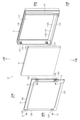
- FIG. 2 is an exploded perspective view showing the display panel housing structure according to the embodiment.
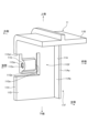
- FIG. 3 is a partially enlarged perspective view of the outer panel of the display panel storage structure according to the embodiment.
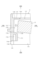
- FIG. 4 is a partially enlarged cross-sectional view of the display panel housing structure according to the embodiment.
- FIG. 5 is a partially enlarged cross-sectional view of the display panel housing structure according to the embodiment.
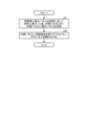
- FIG. 6 is a flowchart illustrating a display panel storage method according to an embodiment.
- the electronic device is, for example, an AV (Audio Visual) integrated car navigation device that is installed inside a vehicle.
- AV Audio Visual
- the front is the side seen by the operator, and corresponds to the front side of the electronic device shown in each figure.
- the side facing the rear of the vehicle is the front side (front).
- the top, bottom, right side, and left side are defined as viewed from the front, and the side opposite the front side is the rear side (rear side).
- the electronic device of the embodiment has a display unit 10.
- the electronic device has a device housing on the rear side of the display unit 10 that houses a control board that controls the display unit 10. Therefore, the display unit 10 is electrically connected to the device housing and attached to the device housing.
- the display unit 10 constitutes the display panel storage structure of the embodiment, and as shown in FIG. 2, includes an exterior panel 11, a display panel 12, and a rear metal plate 13 (rear plate).
- the display panel 12 includes, for example, a liquid crystal display (LCD) or an organic electroluminescence (EL) display.
- the display panel 12 is formed in the shape of a rectangular plate.
- the exterior panel 11 and rear metal plate 13 house the display panel 12 between them.
- the exterior panel 11 is made of synthetic resin material.
- the exterior panel 11 forms the exterior of the display panel 12, surrounding the front, upper, lower, right and left sides.
- the exterior panel 11 has an opening 11F that opens into a rectangular shape at the rear, a front panel 11A on the front side, and upper peripheral wall 11B, lower peripheral wall 11C, right peripheral wall 11D and left peripheral wall 11E that surround the front panel 11A.
- the upper peripheral wall 11B, lower peripheral wall 11C, right peripheral wall 11D and left peripheral wall 11E are also simply referred to as peripheral walls.
- the upper peripheral wall 11B and lower peripheral wall 11C are provided on the relatively long side of the overall rectangular shape of the exterior panel 11, and the right peripheral wall 11D and left peripheral wall 11E are provided on the relatively short short side.
- the front plate 11A has an opening 11Aa that exposes the front of the display panel 12, and a rectangular frame portion 11Ab is formed around the opening 11Aa.
- the front of the display panel 12 viewed from the opening 11Aa is called the display surface 12A.
- the peripheral walls 11B, 11C, 11D, and 11E are provided on the outer periphery of the frame portion 11Ab, protruding toward the rear side. Therefore, the appearance panel 11 covers the edge of the front of the display panel 12 with the frame portion 11Ab excluding the opening 11Aa of the front plate 11A, and surrounds the outer periphery of the display panel 12 with the peripheral walls 11B, 11C, 11D, and 11E.
- the rear sheet metal 13 is made of a metal material.
- the rear sheet metal 13 is formed in a rectangular plate shape so as to close the opening 11F of the exterior panel 11.
- the rear sheet metal 13 has an upper periphery 13B, a lower periphery 13C, a right periphery 13D, and a left periphery 13E that are bent forward from the edge to surround the periphery.
- the upper periphery 13B, the lower periphery 13C, the right periphery 13D, and the left periphery 13E are also simply referred to as peripheries.
- the upper periphery 13B and the lower periphery 13C are provided on the relatively long side of the overall rectangular shape of the rear sheet metal 13, and the right periphery 13D and the left periphery 13E are provided on the relatively short short side.
- the upper periphery 13B, the lower periphery 13C, the right periphery 13D, and the left periphery 13E function as strength parts of the rear sheet metal 13 by bending.
- the rear sheet metal 13 also has through holes 13G.
- the through holes 13G are formed in a total of four locations near the right peripheral edge 13D and the left peripheral edge 13E.
- the through holes 13G are portions through which the screws 14 pass, and the screws 14 are fastened to the bosses 11G of the appearance panel 11 to fix the rear sheet metal 13 to the appearance panel 11.
- the through holes 13G may be cut out.
- the display panel storage structure of this embodiment is characterized by the boss 11G of the exterior panel 11.
- the boss 11G is molded from a synthetic resin material together with the exterior panel 11, as shown in Figs. 3 to 5.
- the boss 11G is provided at the protruding rear end (end on the rear side) of the right side peripheral wall 11D of the exterior panel 11.
- the boss 11G is formed on the surface facing the inside (inside the opening 11F) of the right side peripheral wall 11D of the exterior panel 11.
- the boss 11G is provided to protrude integrally on the inside of the right side peripheral wall 11D of the exterior panel 11.
- the boss 11G has a rear end 11Ga toward the rear side, a front end 11Gb toward the front side, and a screw hole 11Gc formed from the rear end 11Ga toward the front side and opened to the rear side at the rear end 11Ga. Therefore, the screw 14 is inserted into the screw hole 11Gc from the rear side (rear side).
- the boss 11G has a gap 11Gf between itself and the frame 11Ab because its front end 11Gb does not reach the frame 11Ab of the front plate 11A of the appearance panel 11 and is separated from the frame 11Ab.
- the gap 11Gf is the portion into which the periphery of the display panel 12 is inserted.
- the boss 11G is formed by an inclined surface such that the front end 11Gb moves away from the frame 11Ab to the rear as it moves away from the right peripheral wall 11D to the left. In other words, the boss 11G is formed such that the gap 11Gf expands from the frame 11Ab to the rear as it moves away from the right peripheral wall 11D to the left due to the inclined surface of the front end 11Gb.
- the boss 11G is provided with a rear end 11Ga recessed forward from the rear end 11H (the end facing rearward) of the right peripheral wall 11D.
- the boss 11G has a notch 11Gd formed in the rear end 11H of the right peripheral wall 11D, extending from the rear end 11H to the front, and the rear end 11Ga is recessed forward from the rear end 11H via this notch 11Gd.
- the boss 11G has a slit portion 11Ge formed along its periphery in the right peripheral wall 11D.
- the slit portion 11Ge is opened at one end by the notch 11Gd, extends in the front-to-rear direction along the lower side (or upper side) of the boss 11G, and is bent upward (or downward) along the front end 11Gb of the boss 11G, forming an L-shape with the other end closed.
- This slit portion 11Ge allows the boss 11G to be provided on a rectangular plate portion with only one side continuous on the right peripheral wall 11D, and is provided so that it can move left and right by elastic deformation of the plate portion.
- the boss 11G is configured to form the gap 11Gf, and the relationship between the protruding dimension T1 of the front end 11Gb from the right peripheral wall 11D to the left and the protruding dimension T2 of the frame portion 11Ab from the right peripheral wall 11D to the left is in the range of T2/T1 ⁇ 2.0.
- the protruding dimension T2 of the frame portion 11Ab from the right peripheral wall 11D to the left is less than twice the protruding dimension T1 of the front end 11Gb from the right peripheral wall 11D to the left.
- the boss 11G is in the range of T2/T1 ⁇ 1.5. Therefore, the display panel storage structure of the embodiment forms a thin frame in which the protruding dimension T2 of the frame portion 11Ab is relatively small, making the display surface 12A of the display panel 12 appear as large as possible.
- the boss 11G configured in this manner may be provided somewhere other than the right peripheral wall 11D.
- the screw 14 tightened into the screw hole 11Gc of the boss 11G is formed to a length that does not penetrate the front end 11Gb as shown in FIG. 4.
- the screw 14 is formed to a length that does not reach the gap portion 11Gf.
- the display panel storage method for storing the display panel 12 using the display panel storage structure configured in this manner includes the steps of inserting the display panel 12 into the gap 11Gf at an angle relative to the frame 11Ab, and then accommodating the display panel 12 in the appearance panel 11 so that it fits along the frame 11Ab (step S1), as shown in Figures 2, 4 to 6, and tightening the screws 14 into the bosses 11G to attach the rear metal plate 13 to the appearance panel 11 (step S2).
- step S1 the display panel 12 is accommodated in the appearance panel 11 by inserting the periphery of the display panel 12 into the gap 11Gf.
- the gap 11Gf is provided in order to insert the display panel 12 between the boss 11G and the frame 11Ab.
- the front end 11Gb of the boss 11G is formed as an inclined surface, so that the display panel 12 is prevented from hitting the boss 11G, and the display panel 12 can be smoothly accommodated in the appearance panel 11.
- the display panel storage structure of the embodiment includes an appearance panel 11 that houses the display panel 12 and has a frame portion 11Ab on the front side that covers the front edge of the display panel 12 and a right side peripheral wall 11D that protrudes from the outer periphery of the frame portion 11Ab to the rear side so as to surround the outer periphery of the display panel 12, a back metal sheet 13 that is attached to the appearance panel 11 so as to cover the rear side of the display panel 12, a boss 11G that is a protruding rear end portion of the right side peripheral wall 11D of the appearance panel 11 and is provided on the inside surrounding the outer periphery of the display panel 12 and into which a screw 14 that fixes the back metal sheet 13 is fastened, and a gap portion 11Gf that is provided for inserting the display panel 12 between the boss 11G and the frame portion 11Ab.
- the display panel 12 is inserted into the gap 11Gf, making the protruding dimension T2 of the frame 11Ab as small as possible, and a space can be provided inside (rear side) of the frame 11Ab for the periphery of the display panel 12 to fit in. Furthermore, with this display panel storage structure, the display panel 12 is inserted into the gap 11Gf, preventing interference between the display panel 12 and the boss 11G for fixing the back metal plate 13 to the appearance panel 11. Therefore, this display panel storage structure prevents interference between the display panel 12 and the boss 11G, and allows the large-screen display panel 12 to be stored in the appearance panel 11 with a limited area.
- this display panel storage structure fixes the back metal plate 13 to the appearance panel 11 with the screw 14, it is possible to ensure assembly strength and prevent abnormal noise caused by mutual vibration, compared to a configuration in which the back metal plate 13 is attached to the appearance panel 11 by inserting or fitting.
- a notch 11Gd is formed from the rear end 11H of the right side peripheral wall 11D toward the front, and the boss 11G is recessed forward from the rear end 11H via the notch 11Gd.
- the display panel storage structure of the embodiment further includes a slit portion 11Ge that is arranged around the boss 11G in the right peripheral wall 11D and has one end open and the other end closed.
- the plate portion on which the boss 11G formed by the slit portion 11Ge is provided elastically deforms along with the boss 11G. Therefore, in this display panel storage structure, the boss 11G is provided so that its position can be moved by the elastic deformation of the plate portion, so that even if the display panel 12 comes into contact with the boss 11G when inserting the display panel 12 into the gap portion 11Gf, the insertion of the display panel 12 is not impeded. After the display panel 12 is inserted into the gap portion 11Gf, the boss 11G returns to its original position by the elastic deformation of the plate portion.
- the electronic device of the embodiment also employs the display panel storage structure described above.
- This electronic device prevents interference between the display panel 12 and the boss 11G, and allows the large-screen display panel 12 to be stored in the limited surface area of the exterior panel 11. Furthermore, this electronic device ensures the strength of the assembly between the rear metal plate 13 and the exterior panel 11, and prevents abnormal noise caused by vibration between them.
- the display panel storage method of the embodiment also includes the steps of applying the display panel storage structure described above, inserting the display panel 12 into the gap 11Gf at an angle relative to the frame 11Ab, and then storing the display panel 12 in the exterior panel 11 along the frame 11Ab, and tightening the screws 14 into the bosses 11G to attach the rear metal plate 13 to the exterior panel 11.
- This display panel storage method prevents interference between the display panel 12 and the boss 11G, and allows the large-screen display panel 12 to be stored in the limited surface area of the exterior panel 11. Furthermore, this display panel storage method ensures the strength of the assembly between the rear metal plate 13 and the exterior panel 11, and prevents abnormal noise caused by vibration between them.
- the back metal plate 13 is attached to the exterior panel 11 so as to cover the back surface of the display panel 12.
- a resin plate may be attached as the back plate instead of a metal plate.
- the present disclosure makes it possible to store a large-screen display panel within an exterior panel with a limited surface area by preventing interference between the display panel and the boss.
Landscapes
- Physics & Mathematics (AREA)
- Nonlinear Science (AREA)
- General Physics & Mathematics (AREA)
- Engineering & Computer Science (AREA)
- Mathematical Physics (AREA)
- Chemical & Material Sciences (AREA)
- Crystallography & Structural Chemistry (AREA)
- Optics & Photonics (AREA)
- Theoretical Computer Science (AREA)
- Multimedia (AREA)
- Signal Processing (AREA)
- Devices For Indicating Variable Information By Combining Individual Elements (AREA)
Abstract
表示パネルとボスとの干渉を防いで、限られた面積の外観パネルの中に大画面の表示パネルを格納すること。表示パネル格納構造は、表示パネル(12)を収容し、正面側に表示パネル(12)の正面の縁を覆う枠部(11Ab)を有し、枠部(11Ab)の外周に表示パネル(12)の外周を囲むように背面側に突出した右側周壁(11D)を有する外観パネル(11)と、表示パネル(12)の背面を覆うように外観パネル(11)に取り付けられる背面板金(13)と、外観パネル(11)の右側周壁(11D)の突出した後端部であって表示パネル(12)の外周を囲む内側に設けられて背面板金(13)を固定するネジ(14)が締め付けられるボス(11G)と、ボス(11G)と枠部(11Ab)との間に表示パネル(12)を挿入するために設けられた間隙部(11Gf)と、を含む。
Description
本発明は、表示パネル格納構造、電子機器、並びに表示パネル格納方法に関する。
例えば、特許文献1には、画像を表示するための表示装置が示されている。この表示装置は、前面に表示面を有する表示パネルと、表示パネルの背面を覆う背面筐体と、表示面の外周部を覆う前面部から背面筐体側に延びる周面部で表示パネルの外周面を覆う前面筐体と、背面筐体および前面筐体を相互に締結するネジと、を備える。この表示装置では、背面筐体は、前面筐体側に向けてネジが挿入される貫通孔を有し、前面筐体は、周面部の内面に設けられ、貫通孔に挿入されたネジが締結されるボスと、周面部の内面に設けられボスから前面部の内面に向けて延びるリブと、を有する。
ところで、例えば、電子機器は、表示部において、外観パネルに板金を固定して外観パネルと板金との間に液晶パネルのような表示パネルを格納する表示パネル格納構造が採用される。外観パネルは、表示パネルを収容するように背面が開放された枠状に形成される。板金は、表示パネルの背面側を覆うように形成され、外側からネジで外観パネルに固定される。しかし、このような表示パネル格納構造において、特に、限られた面積の外観パネルの中に大画面の表示パネルを格納するように、外観パネルの正面の枠部を薄くする薄型フレームでは、当該枠部の位置でネジを締め込む構造とした場合、ネジを締めるボスやリブが表示パネルに干渉する問題がある。
本開示は、表示パネルとボスとの干渉を防いで、限られた面積の外観パネルの中に大画面の表示パネルを格納することのできる表示パネル格納構造、電子機器、並びに表示パネル格納方法を提供することを目的とする。
上記の目的を達成するため、本開示の一態様の表示パネル格納構造は、表示パネルを収容し、正面側に前記表示パネルの正面の縁を覆う枠部を有し、当該枠部の外周に前記表示パネルの外周を囲むように背面側に突出した周壁を有する外観パネルと、前記表示パネルの背面を覆うように前記外観パネルに取り付けられる背面板と、前記外観パネルの周壁の突出した後端部であって前記表示パネルの外周を囲む内側に設けられて前記背面板を固定するネジが締め付けられるボスと、前記ボスと前記枠部との間に前記表示パネルを挿入するために設けられた間隙部と、を含む。
上記の目的を達成するため、本開示の一態様の電子機器は、上述した表示パネル格納構造が適用される。
上記の目的を達成するため、本開示の一態様の表示パネル格納方法は、上述した表示パネル格納構造を適用し、前記外観パネルに対して前記間隙部に前記表示パネルを前記枠部に対して斜めに挿入した後、前記枠部に沿うように収容する工程と、前記外観パネルに前記背面板を取り付けるように、前記ボスに前記ネジを締め付ける工程と、を含む。
本開示によれば、表示パネルとボスとの干渉を防いで、限られた面積の外観パネルの中に大画面の表示パネルを格納することができる。
以下、本開示を実施するための形態(以下、実施形態という)につき図面を参照しつつ詳細に説明する。なお、下記の実施形態により本開示が限定されるものではない。また、下記実施形態における構成要素には、当業者が容易に想定できるもの、実質的に同一のもの、いわゆる均等の範囲のものが含まれる。さらに、下記実施形態で開示した構成要素は適宜組み合わせることが可能である。
本実施形態に係る電子機器は、車両の内部に搭載される、例えば、AV(Audio Visual)一体型のカーナビゲーション装置である。
ここで、以下の説明において、正面とは、オペレータが視る面であって、各図で示す電子機器の前側に相当する。カーナビゲーション装置の場合は、車内前方に配置されるため、車内の後方に向く側が前側(正面)となる。また、本実施形態において、電子機器および表示パネル格納構造を説明するうえで、前側から視た状態を基準にして、上側、下側、右側、左側とし、前側の反対側を後側(背面)とする。
実施形態の電子機器は、図1に示すように、表示部10を有する。図には明示しないが、電子機器は、表示部10の後側に表示部10を制御する制御基板が収容される機器筐体を有する。従って、表示部10は、機器筐体に電気的に接続され、機器筐体に取り付けられる。
表示部10は、実施形態の表示パネル格納構造をなすものであり、図2に示すように、外観パネル11と、表示パネル12と、背面板金13(背面板)と、を含む。
表示パネル12は、例えば、液晶ディスプレイ(LCD:Liquid Crystal Display)または有機EL(Electro-Luminescence)ディスプレイが含まれる。表示パネル12は、矩形の板状に形成される。
外観パネル11および背面板金13は、その間に表示パネル12を格納する。
外観パネル11は、合成樹脂材からなる。外観パネル11は、表示パネル12において、前側、上側、下側、右側、左側を囲む外観を構成する。外観パネル11は、後側が矩形状に開放する開放部11Fと、前側の正面板11Aと、正面板11Aの周りを囲む上側周壁11B、下側周壁11C、右側周壁11D、および左側周壁11Eと、を有する。上側周壁11B、下側周壁11C、右側周壁11D、および左側周壁11Eは、単に周壁ともいう。上側周壁11Bおよび下側周壁11Cは、外観パネル11の矩形状の全体形状において比較的長い長辺部に設けられ、右側周壁11Dおよび左側周壁11Eは、比較的短い短辺部に設けられる。正面板11Aは、表示パネル12の正面を露わにする開口部11Aaが形成されることで開口部11Aaの周りに矩形状の枠部11Abを有する。当該開口部11Aaから視られる表示パネル12の正面を表示面12Aという。また、周壁11B,11C,11D,11Eは、この枠部11Abの外周において背面側に突出して設けられる。従って、外観パネル11は、その正面板11Aの開口部11Aaを除く枠部11Abで表示パネル12の正面の縁を覆い、周壁11B,11C,11D,11Eで表示パネル12の外周を囲む。
背面板金13は、金属材からなる。背面板金13は、外観パネル11の開放部11Fを塞ぐように矩形の板状に形成される。背面板金13は、その周りを囲むように縁から前側に折り曲げられた上側周縁13B、下側周縁13C、右側周縁13D、および左側周縁13Eを有する。上側周縁13B、下側周縁13C、右側周縁13D、および左側周縁13Eは、単に周縁ともいう。上側周縁13Bおよび下側周縁13Cは、背面板金13の矩形状の全体形状において比較的長い長辺部に設けられ、右側周縁13Dおよび左側周縁13Eは、比較的短い短辺部に設けられる。上側周縁13B、下側周縁13C、右側周縁13D、および左側周縁13Eは、折り曲げ加工によって背面板金13の強度部分として機能する。また、背面板金13は、貫通孔13Gを有する。貫通孔13Gは、右側周縁13Dおよび左側周縁13Eの近傍の計4箇所に形成される。貫通孔13Gは、ネジ14が貫通する部分であり、このネジ14が外観パネル11のボス11Gに締め付けられて背面板金13が外観パネル11に固定される。なお、貫通孔13Gは切欠形状であっても良い。
実施形態の表示パネル格納構造は、外観パネル11のボス11Gに特徴を有する。
ボス11Gは、図3から図5に示すように、外観パネル11と共に合成樹脂材によって成形される。ボス11Gは、実施形態では、外観パネル11の右側周壁11Dの突出した後端部(背面側の端部)に設けられる。ボス11Gは、実施形態では、外観パネル11の右側周壁11Dの内側(開放部11F内)に向く面に形成される。ボス11Gは、外観パネル11の右側周壁11Dの内側に一体に突出して設けられる。ボス11Gは、後側に向けて背面端11Gaを有し、前側に向けて正面端11Gbを有し、背面端11Gaから前側に向けて形成されて背面端11Gaにて後側に開放して開けられたネジ穴11Gcを有して形成される。従って、ネジ穴11Gcに対し、ネジ14は、背面側(後側)から挿入される。
ボス11Gは、正面端11Gbが、外観パネル11の正面板11Aの枠部11Abにまで至らずに枠部11Abとは切り離されることで、枠部11Abとの間に間隙部11Gfを有する。間隙部11Gfは、表示パネル12の周縁が挿入される部分である。ボス11Gは、正面端11Gbが、右側周壁11Dから左側に離れるに連れて、枠部11Abから後側に離れるように傾斜面によって形成される。即ち、ボス11Gは、間隙部11Gfが、正面端11Gbの傾斜面によって、右側周壁11Dから左側に離れるに連れて、枠部11Abから後側に広がるように形成される。
ボス11Gは、背面端11Gaが、右側周壁11Dの後端11H(後側に向く端)よりも前側に凹んだ位置に設けられる。具体的に、ボス11Gは、右側周壁11Dの後端11Hに、当該後端11Hから前側に向かって切欠部11Gdが形成され、この切欠部11Gdを介して後端11Hよりも前側に背面端11Gaが凹んで配置される。
ボス11Gは、右側周壁11Dに対し、自身の周りに沿ってスリット部11Geが形成される。スリット部11Geは、一端が切欠部11Gdにて開放し、前後方向に延びてボス11Gの下側(上側でもよい)に沿い、ボス11Gの正面端11Gbに沿うように上側(下側)に折れ曲がって他端が閉塞したL字形状に形成される。このスリット部11Geによって、ボス11Gは、右側周壁11Dにおいて一辺のみが連続する矩形状の板部に設けられ、当該板部の弾性変形によって左右方向に移動が可能に設けられる。
ボス11Gは、図4に示すように、間隙部11Gfを形成するための構成であって、右側周壁11Dから左側への正面端11Gbの突出寸法T1と、右側周壁11Dから左側への枠部11Abの突出寸法T2との関係が、T2/T1≦2.0の範囲とされる。即ち、右側周壁11Dから左側への枠部11Abの突出寸法T2は、右側周壁11Dから左側への正面端11Gbの突出寸法T1の2倍以下とされている。好ましくは、ボス11Gは、T2/T1≦1.5の範囲とされる。従って、実施形態の表示パネル格納構造は、枠部11Abの突出寸法T2が比較的小さく、表示パネル12の表示面12Aを極力大きく見せられるような薄型フレームを構成する。
このように構成されたボス11Gは、右側周壁11D以外に設けられていてもよい。
また、実施形態の表示パネル格納構造は、ボス11Gのネジ穴11Gcに締め付けられるネジ14が、図4に示すように正面端11Gbを貫通しない長さに形成される。即ち、ネジ14は、間隙部11Gfに至らない長さに形成される。
このように構成された表示パネル格納構造を用いて、表示パネル12を格納する表示パネル格納方法は、図2、図4から図6に示すように、間隙部11Gfに表示パネル12を枠部11Abに対して斜めに挿入した後、枠部11Abに沿うように外観パネル11に表示パネル12を収容する工程(ステップS1)と、外観パネル11に背面板金13を取り付けるように、ボス11Gにネジ14を締め付ける工程(ステップS2)と、を含む。
外観パネル11に表示パネル12を収容する工程(ステップS1)では、図5に示すように、間隙部11Gfに表示パネル12の周縁を挿入するようにして、表示パネル12を外観パネル11に収容する。このように、間隙部11Gfは、ボス11Gと枠部11Abとの間に表示パネル12を挿入するために設けられる。間隙部11Gfに表示パネル12を挿入する際、ボス11Gの正面端11Gbが傾斜面として形成されているため、表示パネル12がボス11Gに突き当たることを防ぎ、外観パネル11への表示パネル12の収容を円滑に行うことができる。
また、ネジ14によって外観パネル11に背面板金13を固定した際、図4に示すように、背面板金13においてネジ14を貫通させる貫通孔13Gの周囲の部分を切欠部11Gdに嵌り込ませ、ネジ14の頭部を右側周壁11Dの後端11Hから後側に突出させない。
このように、実施形態の表示パネル格納構造は、表示パネル12を収容し、正面側に表示パネル12の正面の縁を覆う枠部11Abを有し、当該枠部11Abの外周に表示パネル12の外周を囲むように背面側に突出する右側周壁11Dを有する外観パネル11と、表示パネル12の背面を覆うように外観パネル11に取り付けられる背面板金13と、外観パネル11の右側周壁11Dの突出した後端部であって表示パネル12の外周を囲む内側に設けられて背面板金13を固定するネジ14が締め付けられるボス11Gと、ボス11Gと枠部11Abとの間に表示パネル12を挿入するために設けられた間隙部11Gfと、を含む。
この表示パネル格納構造によれば、間隙部11Gfに表示パネル12が挿入されることで、枠部11Abの突出寸法T2を極力小さくした薄型フレームとし、当該枠部11Abの内側(後側)に表示パネル12の周縁を入り込ませるスペースを設けることができる。しかも、この表示パネル格納構造は、間隙部11Gfに表示パネル12が挿入されることで、背面板金13を外観パネル11に固定するためのボス11Gと表示パネル12との干渉を防ぐことができる。従って、この表示パネル格納構造は、表示パネル12とボス11Gとの干渉を防いで、限られた面積の外観パネル11の中に大画面の表示パネル12を格納することができる。しかも、この表示パネル格納構造は、ネジ14で背面板金13を外観パネル11に固定するため、差し込みや嵌め込みで背面板金13を外観パネル11に取り付ける構成と比較して、組み付け強度を確保し、かつ相互の振動による異音の発生を防ぐことができる。
また、実施形態の表示パネル格納構造では、右側周壁11Dの後端11Hから前側に向かって切欠部11Gdが形成され、ボス11Gは、切欠部11Gdを介して後端11Hよりも前側に凹んで配置される。
この表示パネル格納構造によれば、ボス11Gを介してネジ14によって背面板金13を外観パネル11に固定した際、背面板金13においてネジ14を貫通させる貫通孔13Gの周囲の部分、およびネジ14の頭部を、右側周壁11Dの後端11Hから後側に飛び出させない。従って、この表示パネル格納構造は、背面板金13やネジ14が突起とならずに、他部材(例えば、機器筐体)との干渉を防ぐことができる。
また、実施形態の表示パネル格納構造では、右側周壁11Dにおいてボス11Gの周りに沿って配置されて一端が開放し他端が閉塞されるスリット部11Geをさらに含む。
この表示パネル格納構造によれば、スリット部11Geによって形成されたボス11Gが設けられた板部がボス11Gを伴って弾性変形する。従って、この表示パネル格納構造は、ボス11Gが板部の弾性変形によって位置が移動可能に設けられるため、間隙部11Gfに表示パネル12を挿入する際に表示パネル12がボス11Gに接触しても表示パネル12の挿入を妨げない。間隙部11Gfに表示パネル12を挿入した後は、ボス11Gが板部の弾性変形によって元の位置に戻る。
また、実施形態の電子機器は、上述した表示パネル格納構造が適用される。
この電子機器によれば、表示パネル12とボス11Gとの干渉を防いで、限られた面積の外観パネル11の中に大画面の表示パネル12を格納することができる。しかも、この電子機器によれば、背面板金13と外観パネル11との組み付け強度を確保し、かつ相互の振動による異音の発生を防ぐことができる。
また、実施形態の表示パネル格納方法は、上述した表示パネル格納構造を適用し、間隙部11Gfに表示パネル12を枠部11Abに対して斜めに挿入した後、枠部11Abに沿うように外観パネル11に収容する工程と、外観パネル11に背面板金13を取り付けるように、ボス11Gにネジ14を締め付ける工程と、を含む。
この表示パネル格納方法によれば、表示パネル12とボス11Gとの干渉を防いで、限られた面積の外観パネル11の中に大画面の表示パネル12を格納することができる。しかも、この表示パネル格納方法によれば、背面板金13と外観パネル11との組み付け強度を確保し、かつ相互の振動による異音の発生を防ぐことができる。
なお、実施形態では、表示パネル12の背面を覆うように背面板金13を外観パネル11に取り付けると説明したが、背面板として取り付けるのは背面板金13の他に、板金に替えて樹脂製の板でもよい。
本開示は、表示パネルとボスとの干渉を防いで、限られた面積の外観パネルの中に大画面の表示パネルを格納することができる。
11 外観パネル
11D 右側周壁
11Ab 枠部
11G ボス
11Ga 背面端
11Gb 正面端
11Gd 切欠部
11Ge スリット部
11Gf 間隙部
11H 後端
12 表示パネル
13 背面板金(背面板)
14 ネジ
11D 右側周壁
11Ab 枠部
11G ボス
11Ga 背面端
11Gb 正面端
11Gd 切欠部
11Ge スリット部
11Gf 間隙部
11H 後端
12 表示パネル
13 背面板金(背面板)
14 ネジ
Claims (5)
- 表示パネルを収容し、正面側に前記表示パネルの正面の縁を覆う枠部を有し、当該枠部の外周に前記表示パネルの外周を囲むように背面側に突出した周壁を有する外観パネルと、
前記表示パネルの背面を覆うように前記外観パネルに取り付けられる背面板と、
前記外観パネルの周壁の突出した後端部であって前記表示パネルの外周を囲む内側に設けられて前記背面板を固定するネジが締め付けられるボスと、
前記ボスと前記枠部との間に前記表示パネルを挿入するために設けられた間隙部と、
を含む、表示パネル格納構造。 - 前記周壁の後端から正面に向かって切欠部が形成され、前記ボスは、前記切欠部を介して前記後端よりも正面側に凹んで配置される、請求項1に記載の表示パネル格納構造。
- 前記周壁において前記ボスの周りに沿って配置されて一端が開放し他端が閉塞されるスリット部をさらに含む、請求項1または2に記載の表示パネル格納構造。
- 表示パネルを収容し、正面側に前記表示パネルの正面の縁を囲む枠部を有し、当該枠部の外周に前記表示パネルの外周を囲むように背面側に突出した周壁を有する外観パネルと、
前記表示パネルの背面を覆うように前記外観パネルに取り付けられる背面板と、
前記外観パネルの周壁の突出した後端部であって前記表示パネルの外周を囲む内側に設けられて前記背面板を固定するネジが締め付けられるボスと、
前記ボスと前記枠部との間に前記表示パネルを挿入するために設けられた間隙部と、
を含む、表示パネル格納構造が適用される、電子機器。 - 表示パネルを収容し、正面側に前記表示パネルの正面の縁を囲む枠部を有し、当該枠部の外周に前記表示パネルの外周を囲むように背面側に突出した周壁を有する外観パネルと、
前記表示パネルの背面を覆うように前記外観パネルに取り付けられる背面板と、
前記外観パネルの周壁の突出した後端部であって前記表示パネルの外周を囲む内側に設けられて前記背面板を固定するネジが締め付けられるボスと、
前記ボスと前記枠部との間に前記表示パネルを挿入するために設けられた間隙部と、
を含む、表示パネル格納構造を適用し、
前記間隙部に前記表示パネルを前記枠部に対して斜めに挿入した後、前記枠部に沿うように前記外観パネルに収容する工程と、
前記外観パネルに前記背面板を取り付けるように、前記ボスに前記ネジを締め付ける工程と、
を含む、表示パネル格納方法。
Priority Applications (2)
| Application Number | Priority Date | Filing Date | Title |
|---|---|---|---|
| JP2025526006A JPWO2024252852A1 (ja) | 2023-06-06 | 2024-05-13 | |
| CN202480024128.3A CN121002838A (zh) | 2023-06-06 | 2024-05-13 | 显示面板收纳结构、电子设备以及显示面板收纳方法 |
Applications Claiming Priority (2)
| Application Number | Priority Date | Filing Date | Title |
|---|---|---|---|
| JP2023093156 | 2023-06-06 | ||
| JP2023-093156 | 2023-06-06 |
Publications (1)
| Publication Number | Publication Date |
|---|---|
| WO2024252852A1 true WO2024252852A1 (ja) | 2024-12-12 |
Family
ID=93795259
Family Applications (1)
| Application Number | Title | Priority Date | Filing Date |
|---|---|---|---|
| PCT/JP2024/017579 Ceased WO2024252852A1 (ja) | 2023-06-06 | 2024-05-13 | 表示パネル格納構造、電子機器、並びに表示パネル格納方法 |
Country Status (3)
| Country | Link |
|---|---|
| JP (1) | JPWO2024252852A1 (ja) |
| CN (1) | CN121002838A (ja) |
| WO (1) | WO2024252852A1 (ja) |
Citations (4)
| Publication number | Priority date | Publication date | Assignee | Title |
|---|---|---|---|---|
| JP2008164803A (ja) * | 2006-12-27 | 2008-07-17 | Toshiba Corp | 筐体およびディスプレイ用筐体 |
| WO2013069592A1 (ja) * | 2011-11-09 | 2013-05-16 | シャープ株式会社 | 照明装置、表示装置及びテレビ受信装置 |
| WO2015002017A1 (ja) * | 2013-07-01 | 2015-01-08 | シャープ株式会社 | 照明装置、表示装置、及びテレビ受信装置 |
| JP2015203707A (ja) * | 2014-04-10 | 2015-11-16 | 船井電機株式会社 | 表示装置 |
-
2024
- 2024-05-13 JP JP2025526006A patent/JPWO2024252852A1/ja active Pending
- 2024-05-13 CN CN202480024128.3A patent/CN121002838A/zh active Pending
- 2024-05-13 WO PCT/JP2024/017579 patent/WO2024252852A1/ja not_active Ceased
Patent Citations (4)
| Publication number | Priority date | Publication date | Assignee | Title |
|---|---|---|---|---|
| JP2008164803A (ja) * | 2006-12-27 | 2008-07-17 | Toshiba Corp | 筐体およびディスプレイ用筐体 |
| WO2013069592A1 (ja) * | 2011-11-09 | 2013-05-16 | シャープ株式会社 | 照明装置、表示装置及びテレビ受信装置 |
| WO2015002017A1 (ja) * | 2013-07-01 | 2015-01-08 | シャープ株式会社 | 照明装置、表示装置、及びテレビ受信装置 |
| JP2015203707A (ja) * | 2014-04-10 | 2015-11-16 | 船井電機株式会社 | 表示装置 |
Also Published As
| Publication number | Publication date |
|---|---|
| CN121002838A (zh) | 2025-11-21 |
| JPWO2024252852A1 (ja) | 2024-12-12 |
Similar Documents
| Publication | Publication Date | Title |
|---|---|---|
| JP2006019674A (ja) | 電子装置の筐体構造 | |
| JP2000168466A (ja) | グロメットおよびグロメットの固定構造 | |
| JPH08316664A (ja) | 小型電子機器のスイッチ部基板の保持構造 | |
| JP2005150545A (ja) | 電子装置の筐体構造 | |
| CN109979420B (zh) | 音响设备以及电子乐器 | |
| JP5058258B2 (ja) | 開閉型ディスプレイ装置 | |
| JP2018122658A (ja) | 車室内前部構造 | |
| CN121002838A (zh) | 显示面板收纳结构、电子设备以及显示面板收纳方法 | |
| JPWO2021005674A1 (ja) | 車載表示装置 | |
| JP2731511B2 (ja) | パチンコ機の電気制御装置 | |
| JP7578099B2 (ja) | ヒートインシュレータ | |
| JPH08240377A (ja) | 操作パネルの取付構造 | |
| KR101306126B1 (ko) | 힌지커버 | |
| JP2005100570A (ja) | 車両用電子機器 | |
| KR20060005807A (ko) | 수납물 이탈방지용 글로브박스 | |
| JP4674801B2 (ja) | 電子機器における操作釦取付け構造 | |
| JP2002285962A (ja) | 圧縮機の電装部品 | |
| JP7626010B2 (ja) | 車載装置 | |
| JP2024171749A (ja) | 表示パネル格納構造、電子機器、並びに表示パネル格納方法 | |
| JP3212247B2 (ja) | 筐体構造 | |
| JPS6023217Y2 (ja) | 自動車用パネルの取付構造 | |
| JP3373120B2 (ja) | グローブボックス | |
| JPH0516358Y2 (ja) | ||
| JP2521941Y2 (ja) | ボックス | |
| KR0124854Y1 (ko) | 음향발생장치를 갖는 전자제품의 스피커그릴 고정장치 |
Legal Events
| Date | Code | Title | Description |
|---|---|---|---|
| 121 | Ep: the epo has been informed by wipo that ep was designated in this application |
Ref document number: 24819089 Country of ref document: EP Kind code of ref document: A1 |
|
| WWE | Wipo information: entry into national phase |
Ref document number: 2025526006 Country of ref document: JP |
|
| NENP | Non-entry into the national phase |
Ref country code: DE |