WO2024252678A1 - ヒータ線保持基材 - Google Patents
ヒータ線保持基材 Download PDFInfo
- Publication number
- WO2024252678A1 WO2024252678A1 PCT/JP2023/021588 JP2023021588W WO2024252678A1 WO 2024252678 A1 WO2024252678 A1 WO 2024252678A1 JP 2023021588 W JP2023021588 W JP 2023021588W WO 2024252678 A1 WO2024252678 A1 WO 2024252678A1
- Authority
- WO
- WIPO (PCT)
- Prior art keywords
- heat
- nonwoven fabric
- layer
- heater wire
- holding substrate
- Prior art date
- Legal status (The legal status is an assumption and is not a legal conclusion. Google has not performed a legal analysis and makes no representation as to the accuracy of the status listed.)
- Ceased
Links
Images



Classifications
-
- H—ELECTRICITY
- H05—ELECTRIC TECHNIQUES NOT OTHERWISE PROVIDED FOR
- H05B—ELECTRIC HEATING; ELECTRIC LIGHT SOURCES NOT OTHERWISE PROVIDED FOR; CIRCUIT ARRANGEMENTS FOR ELECTRIC LIGHT SOURCES, IN GENERAL
- H05B3/00—Ohmic-resistance heating
- H05B3/20—Heating elements having extended surface area substantially in a two-dimensional [2D] plane, e.g. plate-heater
-
- B—PERFORMING OPERATIONS; TRANSPORTING
- B29—WORKING OF PLASTICS; WORKING OF SUBSTANCES IN A PLASTIC STATE IN GENERAL
- B29C—SHAPING OR JOINING OF PLASTICS; SHAPING OF MATERIAL IN A PLASTIC STATE, NOT OTHERWISE PROVIDED FOR; AFTER-TREATMENT OF THE SHAPED PRODUCTS, e.g. REPAIRING
- B29C65/00—Joining or sealing of preformed parts, e.g. welding of plastics materials; Apparatus therefor
- B29C65/02—Joining or sealing of preformed parts, e.g. welding of plastics materials; Apparatus therefor by heating, with or without pressure
-
- B—PERFORMING OPERATIONS; TRANSPORTING
- B29—WORKING OF PLASTICS; WORKING OF SUBSTANCES IN A PLASTIC STATE IN GENERAL
- B29C—SHAPING OR JOINING OF PLASTICS; SHAPING OF MATERIAL IN A PLASTIC STATE, NOT OTHERWISE PROVIDED FOR; AFTER-TREATMENT OF THE SHAPED PRODUCTS, e.g. REPAIRING
- B29C70/00—Shaping composites, i.e. plastics material comprising reinforcements, fillers or preformed parts, e.g. inserts
- B29C70/02—Shaping composites, i.e. plastics material comprising reinforcements, fillers or preformed parts, e.g. inserts comprising combinations of reinforcements, e.g. non-specified reinforcements, fibrous reinforcing inserts and fillers, e.g. particulate fillers, incorporated in matrix material, forming one or more layers and with or without non-reinforced or non-filled layers
- B29C70/021—Combinations of fibrous reinforcement and non-fibrous material
-
- B—PERFORMING OPERATIONS; TRANSPORTING
- B29—WORKING OF PLASTICS; WORKING OF SUBSTANCES IN A PLASTIC STATE IN GENERAL
- B29C—SHAPING OR JOINING OF PLASTICS; SHAPING OF MATERIAL IN A PLASTIC STATE, NOT OTHERWISE PROVIDED FOR; AFTER-TREATMENT OF THE SHAPED PRODUCTS, e.g. REPAIRING
- B29C70/00—Shaping composites, i.e. plastics material comprising reinforcements, fillers or preformed parts, e.g. inserts
- B29C70/04—Shaping composites, i.e. plastics material comprising reinforcements, fillers or preformed parts, e.g. inserts comprising reinforcements only, e.g. self-reinforcing plastics
- B29C70/06—Fibrous reinforcements only
- B29C70/10—Fibrous reinforcements only characterised by the structure of fibrous reinforcements, e.g. hollow fibres
- B29C70/12—Fibrous reinforcements only characterised by the structure of fibrous reinforcements, e.g. hollow fibres using fibres of short length, e.g. in the form of a mat
-
- B—PERFORMING OPERATIONS; TRANSPORTING
- B29—WORKING OF PLASTICS; WORKING OF SUBSTANCES IN A PLASTIC STATE IN GENERAL
- B29C—SHAPING OR JOINING OF PLASTICS; SHAPING OF MATERIAL IN A PLASTIC STATE, NOT OTHERWISE PROVIDED FOR; AFTER-TREATMENT OF THE SHAPED PRODUCTS, e.g. REPAIRING
- B29C70/00—Shaping composites, i.e. plastics material comprising reinforcements, fillers or preformed parts, e.g. inserts
- B29C70/04—Shaping composites, i.e. plastics material comprising reinforcements, fillers or preformed parts, e.g. inserts comprising reinforcements only, e.g. self-reinforcing plastics
- B29C70/28—Shaping operations therefor
- B29C70/30—Shaping by lay-up, i.e. applying fibres, tape or broadsheet on a mould, former or core; Shaping by spray-up, i.e. spraying of fibres on a mould, former or core
-
- D—TEXTILES; PAPER
- D04—BRAIDING; LACE-MAKING; KNITTING; TRIMMINGS; NON-WOVEN FABRICS
- D04H—MAKING TEXTILE FABRICS, e.g. FROM FIBRES OR FILAMENTARY MATERIAL; FABRICS MADE BY SUCH PROCESSES OR APPARATUS, e.g. FELTS, NON-WOVEN FABRICS; COTTON-WOOL; WADDING ; NON-WOVEN FABRICS FROM STAPLE FIBRES, FILAMENTS OR YARNS, BONDED WITH AT LEAST ONE WEB-LIKE MATERIAL DURING THEIR CONSOLIDATION
- D04H13/00—Other non-woven fabrics
-
- H—ELECTRICITY
- H05—ELECTRIC TECHNIQUES NOT OTHERWISE PROVIDED FOR
- H05B—ELECTRIC HEATING; ELECTRIC LIGHT SOURCES NOT OTHERWISE PROVIDED FOR; CIRCUIT ARRANGEMENTS FOR ELECTRIC LIGHT SOURCES, IN GENERAL
- H05B3/00—Ohmic-resistance heating
- H05B3/02—Details
- H05B3/06—Heater elements structurally combined with coupling elements or holders
-
- D—TEXTILES; PAPER
- D10—INDEXING SCHEME ASSOCIATED WITH SUBLASSES OF SECTION D, RELATING TO TEXTILES
- D10B—INDEXING SCHEME ASSOCIATED WITH SUBLASSES OF SECTION D, RELATING TO TEXTILES
- D10B2403/00—Details of fabric structure established in the fabric forming process
- D10B2403/03—Shape features
- D10B2403/033—Three dimensional fabric, e.g. forming or comprising cavities in or protrusions from the basic planar configuration, or deviations from the cylindrical shape as generally imposed by the fabric forming process
- D10B2403/0331—Three dimensional fabric, e.g. forming or comprising cavities in or protrusions from the basic planar configuration, or deviations from the cylindrical shape as generally imposed by the fabric forming process with one or more convex or concave portions of limited extension, e.g. domes or pouches
-
- H—ELECTRICITY
- H05—ELECTRIC TECHNIQUES NOT OTHERWISE PROVIDED FOR
- H05B—ELECTRIC HEATING; ELECTRIC LIGHT SOURCES NOT OTHERWISE PROVIDED FOR; CIRCUIT ARRANGEMENTS FOR ELECTRIC LIGHT SOURCES, IN GENERAL
- H05B2203/00—Aspects relating to Ohmic resistive heating covered by group H05B3/00
- H05B2203/017—Manufacturing methods or apparatus for heaters
Definitions
- the present invention relates to a heater wire holding substrate.
- planar heaters in which a cord-like heating element is fixed to various substrates are known.
- One form of such planar heater is widely known as an electric carpet, which has been in practical use for a long time.
- An electric carpet has a structure in which, for example, a heat-sealing layer is provided on the surface of a heat-insulating substrate such as a thick nonwoven fabric such as felt or polyurethane foam, on which a cord-like heating element with a heat-sealing layer on its surface is arranged in a serpentine manner, and on top of that a skin is further placed, and these laminates are fused and fixed by thermocompression.
- Stitched planar heaters in which a cord-like heating element is sewn and fixed to a nonwoven fabric or the like are also known.
- Patent Document 1 discloses a sheet heater used as a seat heater for an automobile.
- An automobile seat heater has a structure in which a sheet heater is fixed to, for example, an insulating seat cushion with double-sided adhesive tape, and a skin cover is placed on top of it without being fixed.
- Such sheet heaters are required to have various performance properties, such as quick heating, uniform heating, energy saving, bending durability, and contact sensation.
- electric vehicles which have become increasingly popular in recent years, require excellent energy saving performance to extend the driving distance per charge and maintain heating during snowy traffic jams.
- excellent performance is also required for the heater wire holding substrate that fixes the cord-shaped heating element.
- the objective of the present invention is to provide an excellent heater wire holding substrate.
- the heater wire holding substrate comprises a nonwoven fabric layer containing a nonwoven fabric, and a heat-sealable resin layer containing an extruded heat-sealable resin material and heat-sealed onto the nonwoven fabric layer, the heat-sealed nonwoven fabric layer and the heat-sealable resin layer have a plurality of recesses in which the heat-sealable resin layer penetrates in the depth direction of the nonwoven fabric layer, the recesses form a mixed adhesion layer in which the nonwoven fabric and the heat-sealable resin material are mixed, and the amount of sinking of the surface of the nonwoven fabric layer in the recesses is 10 ⁇ m or more and is equal to or less than the thickness dimension of the heat-sealable resin layer.
- the present invention provides an excellent heater wire holding substrate.
- FIG. 5 is a schematic cross-sectional view showing an outline of a configuration example in the vicinity of the surface of a heater wire holding substrate according to a fourth embodiment.
- FIG. 6 is a schematic cross-sectional view illustrating an example of the configuration of the vicinity of the surface of a heater wire holding substrate according to a fifth embodiment.
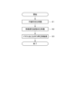
- FIG. 7 is a flow chart showing an outline of an example of a method for manufacturing a heater wire holding substrate according to an embodiment.
- This embodiment relates to a planar heater that can be used, for example, as a seat heater.
- the planar heater of this embodiment uses a cord-shaped heating element that has been reliable and cost-effective as a seat heater for many years.
- This cord-shaped heating element is provided on a heater wire holding substrate.
- the heater wire holding substrate of this embodiment is particularly configured to maximize energy saving effects and various other effects.
- nonwoven fabric is used for the heater wire holding substrate.
- Nonwoven fabric has various advantages, such as being suitable for sewing or gluing to hold the heater wire, having excellent bending resistance, being flame retardant, and being inexpensive.
- inexpensive, thin nonwoven fabric with a low basis weight has a low insulating effect, and a planar heater using such nonwoven fabric has a slow temperature rise rate and relatively low energy saving performance.
- the heater wire holding substrate of this embodiment uses nonwoven fabric, and its disadvantages are overcome while maintaining its advantages.
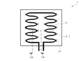
- FIG. 1A is a schematic plan view showing an outline of a configuration example of a sheet heater 1 according to this embodiment.
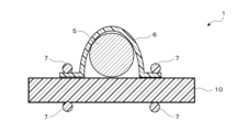
- Fig. 1B is a schematic cross-sectional view showing an outline of a cross section of the sheet heater 1 taken along line IB-IB shown in Fig. 1A.
- the sheet heater 1 has a structure in which a cord-shaped heating element 5 is fixed onto a heater wire holding substrate 10.
- the cord-shaped heating element 5 is fixed to the heater wire holding substrate 10 by sewing with an upper thread 6 and a lower thread 7.
- the cord-shaped heating element 5 is laid on the surface of the heater wire holding substrate 10 according to a pattern program of an automatic sewing machine, and is sewn and fixed to the heater wire holding substrate 10 by, for example, zigzag stitching with the upper thread 6 and the lower thread 7.
- the strength and slackness with which the cord-shaped heating element 5 is fixed can be adjusted by appropriately adjusting the sewing speed, stitch width, thread tension, etc.
- the method of fixing the cord-shaped heating element 5 to the heater wire holding substrate 10 is not limited to sewing, but may be, for example, fused using a heat-sealing resin or bonded using an adhesive.
- Fig. 2 is a schematic cross-sectional view showing an outline of a configuration example near the surface of the heater wire holding substrate 11 according to this embodiment.
- the heater wire holding substrate 11 has a structure in which a heat-fusible resin layer 32 is provided on a nonwoven fabric layer 31.
- the nonwoven fabric layer 31 is preferably formed of a nonwoven fabric material including a nonwoven fabric 21 having a basis weight of 80 g/m 2 or more and 350 g/m 2 or less.
- the nonwoven fabric layer 31 is more preferably formed of a nonwoven fabric material including a nonwoven fabric 21 having a basis weight of 100 g/m 2 or more and 200 g/m 2 or less.
- the material of the nonwoven fabric 21 is, for example, a polyolefin resin. If the basis weight of the nonwoven fabric 21 is less than 80 g/m 2 , the nonwoven fabric 21 is weak, and when the cord-shaped heating element 5 is fixed to the completed heater wire holding substrate 11, the heater wire holding substrate 11 may be distorted due to the rigidity of the cord-shaped heating element 5.
- the basis weight of the nonwoven fabric 21 is less than 80 g/m 2 , the breathability is good but the heat retention is poor, so that there is a possibility that the energy saving property is also poor.
- the basis weight of the nonwoven fabric 21 is more than 350 g/ m2 , when the completed heater wire holding substrate 11 is used, for example, in a seat heater, there is a risk that the fabric will feel undesirably stiff when seated.
- the price of the nonwoven fabric 21 increases in direct proportion to the basis weight, a nonwoven fabric 21 with too high a basis weight is also economically undesirable.
- a heat-sealable resin material 22 formed by extruding a heat-sealable resin is placed on the nonwoven fabric material, and the heat-sealable resin material 22 is pressed and heat-sealed to the nonwoven fabric material over the entire surface thereof to form a heat-sealable resin layer 32.
- This heat-sealable resin is, for example, a polyolefin-based resin.
- the reason for selecting a polyolefin-based heat-sealable resin is that the material of general nonwoven fabrics is polyolefin-based, and that even if it is flame-retardant, it is relatively inexpensive.
- polyolefin resins or olefin-based copolymers can be used alone or in combination of two or more types.
- polyethylene for example, polyethylene, polypropylene, polybutene, etc.
- Polyethylene includes high-density polyethylene, low-density polyethylene, linear low-density polyethylene, etc.
- olefin-based copolymer a copolymer of ethylene and any of propylene, vinyl acetate, acrylic acid, ethyl acrylate, vinyl chloride, etc., a copolymer of propylene and vinyl chloride, etc., or a modified product thereof can be used.
- polyolefin-based resins used in this embodiment are preferably polyolefin copolymers rather than polyethylene alone, as they are more likely to impart flame retardancy and take into consideration the melting point, heat fusion properties, and cost.
- the heat-sealable resin material 22 used in the heat-sealable resin layer 32 can be formed, for example, by molding a commercially available polyolefin copolymer compound into a film using a biaxial stretching device.
- the thickness of the heat-sealable resin layer 32 which is substantially equivalent to the thickness of the heat-sealable resin material 22, is preferably, for example, 0.03 mm to 0.5 mm.
- the thickness of the heat-sealable resin layer 32 is more preferably, for example, 0.03 mm to 0.35 mm, and even more preferably, for example, 0.05 mm to 0.15 mm.
- the above-mentioned pressure heat fusion is performed by a hot press or the like equipped with an upper die having multiple protrusions. Since the upper die has multiple protrusions, this process is called debossing. As a result, multiple recesses 33 are formed on the surface of the heater wire holding substrate 11, in which the heat-sealable resin layer 32 penetrates the nonwoven fabric layer 31 in the depth direction.
- the molten heat-sealable resin layer 32 penetrates not only the surface of the nonwoven fabric layer 31 but also in the depth direction of the recesses 33, and is fused to the nonwoven fabric layer 31 on the side of the recesses 33 and fixed to the nonwoven fabric layer 31. In this way, a mixed fixed layer 41 in which the nonwoven fabric layer 31 and the heat-sealable resin layer 32 are mixed is formed.
- Heat fusion may be performed using a continuous heating roll device or the like.
- the nonwoven fabric layer 31 and the heat-sealable resin layer 32 are preferably as follows in the depth direction. That is, the recess 33 is formed by the heat-sealable resin layer 32 sinking further than the portions other than the recess 33. As the heat-sealable resin layer 32 sinks, the nonwoven fabric layer 31 also sinks further than the portions other than the recess 33 in the recess 33.
- the amount of sinking of the surface of the nonwoven fabric layer 31 in the recess 33 that is, the step between the surface position of the nonwoven fabric layer 31 in the portions other than the recess 33 and the surface position of the nonwoven fabric layer 31 in the recess 33, is preferably within a predetermined range.
- the amount of sinking of the nonwoven fabric layer 31 in the recess 33 is preferably 10 ⁇ m or more and less than the thickness dimension of the heat-sealable resin layer 32. It is even more preferable that the amount of sinking of the nonwoven fabric layer 31 in the recess 33 is 30 ⁇ m or more and less than 1/2 the thickness dimension of the heat-sealable resin layer 32.
- the amount of sinking of the surface of the nonwoven fabric layer 31 is less than 10 ⁇ m, the formation of the mixed adhesive layer 41 will be insufficient, and the effect of suppressing the occurrence of pinholes and wrinkles described below may not be fully achieved. Furthermore, if the amount of sinking of the surface of the nonwoven fabric layer 31 is greater than the thickness dimension of the heat-sealable resin layer 32, cracks are likely to occur at the ends of the recesses 33 in the heat-sealable resin layer 32 when the recesses 33 are formed. If cracks occur, the mechanical strength of the heater wire holding substrate 11 may decrease, and the effect of suppressing the occurrence of pinholes and wrinkles described below may not be fully achieved.
- each recess 33 on the surface of the heat-sealable resin layer 32 is preferably, for example, 1 mm or more at its maximum part. It is even more preferable that the width of each recess 33 on the surface of the heat-sealable resin layer 32 is, for example, 3 mm to 5 mm at its maximum part.
- the diameter is 1 mm or more.
- the diameter is 3 mm to 5 mm.
- the shape of the protrusions provided on the upper die of the hot press is preferably, for example, a cylindrical shape or a truncated cone shape. If the shape of the protrusions is a rectangular column shape with corners, there is a risk that the heat-sealable resin layer 32 may crack when the protrusions are pressed in, so the shape of the protrusions is preferably a shape without corners. In addition, since the molten resin of the heat-sealable resin material 22 is pressed into the soft and shapeless nonwoven fabric 21, in order to make the die removal smooth, the shape of the protrusions is preferably a truncated cone shape with a slightly larger taper angle than a cylinder.
- the protrusions may be, for example, a truncated cone shape with a diameter of 5 mm at the lower base and a diameter of 3 mm at the upper base.
- the size of the protrusions is appropriately adjusted, for example, so that the size of the recess 33 formed in the heater wire holding substrate 11 is as described above.
- the recesses 33 are preferably provided at a density of, for example, one or more recesses per 5 cm square. It is even more preferable that the recesses 33 are provided at a density of, for example, one or more recesses per 2 cm to 3 cm square.
- the fusion density distribution with the heat-sealing film is also random, and the shrinkage distribution of the above-mentioned heat-sealing film is also random.
- shrinkage irregularities occur in the heat-sealing film, pinholes and wrinkles are likely to occur in the heat-sealing film, and the heater wire holding substrate as a whole is prone to distortion and deformation.
- the heater wire holding substrate 11 has a recess 33 formed by debossing.
- the contraction force of the heat-sealable resin material 22, which occurs when the nonwoven fabric 21 and the heat-sealable resin material 22, such as a heat-sealable film, are heat-sealed is alleviated by the recess 33, and the effect of heat shrinkage does not extend over a wide area.
- the heat-sealable resin material 22 melts and penetrates into the nonwoven fabric 21 not only on the surface of the nonwoven fabric 21 but also on the side of the recess 33, increasing the contact opportunity between the heat-sealable resin layer 32 and the nonwoven fabric layer 31, and the heat-sealable resin material 22 strongly embraces the nonwoven fabric 21 to form a mixed fixed layer 41. Therefore, the contraction force of the heat-sealable resin layer 32 is alleviated by the recess 33 and does not extend over a wide area. As a result, the number of pinholes and wrinkles that may occur in the heat-sealable resin layer 32 due to heat shrinkage is reduced. In addition, the heater wire holding substrate 11 as a whole is less likely to be distorted, and a heater wire holding substrate 11 with high flatness can be achieved.
- the heat-sealing resin layer 32 blocks air flow between the inside and outside of the nonwoven fabric layer 31, making it difficult for heat from the cord-shaped heating element 5 to diffuse into the nonwoven fabric layer 31, which has many voids.
- the heater wire holding substrate 11 of this embodiment functions like an insulating material.
- the heat from the cord-shaped heating element 5 is easily diffused in the planar direction by the heat-sealing resin layer 32, which is a continuous solid.
- these configurations realize a heater wire holding substrate 11 that is advantageous for energy saving, even though it uses a thin nonwoven fabric 21 with a low basis weight as the base material.
- the sheet heater 1 can achieve high energy saving performance.
- the thickness of the heat-sealable resin layer 32 is preferably 0.03 mm to 0.5 mm as described above is that if the thickness of the heat-sealable resin layer 32 is thinner than 0.03 mm, even if the recesses 33 are provided, there is a risk of numerous pinholes occurring due to the thermal contraction force during heat fusion. Also, if the thickness of the heat-sealable resin layer 32 is thicker than 0.5 mm, there is a risk of distortion in the nonwoven fabric layer 31, which may reduce the yield of seat heater production. Also, if the thickness of the heat-sealable resin layer 32 is thicker than 0.5 mm, the rise time when the seat heater heats up becomes longer and the overshoot becomes larger, which may increase power consumption and reduce energy-saving performance.
- FIG. 3 is a schematic cross-sectional view showing an outline of a configuration example near the surface of the heater wire holding substrate 12 according to this embodiment.
- the heater wire holding substrate 12 of this embodiment also has a structure in which a heat-sealable resin layer 32 is provided on a nonwoven fabric layer 31.
- the nonwoven fabric structure constituting the nonwoven fabric layer 31 is a nonwoven fabric 21 having aluminum fine particles 26 attached to the surface thereof.
- the aluminum particles 26 can be attached to the surface of the nonwoven fabric 21 by, for example, gas phase deposition, such as vacuum deposition, sputtering, plasma spraying, etc.
- gas phase deposition such as vacuum deposition, sputtering, plasma spraying, etc.
- vacuum deposition aluminum is deposited at the atomic level, so the aluminum deposition layer formed is dense, which is preferable in terms of thermal conduction.
- Sputtering and plasma spraying have a high deposition rate, but the aluminum deposition layer formed is a deposition of granular matter, albeit very small, and contains voids even though they are very small.
- the gas phase deposition method the amount of aluminum particles 26 decreases with the depth of the nonwoven fabric 21. Furthermore, the aluminum particles 26 are not attached to surfaces that are in the shadow of the aluminum evaporation source.
- the aluminum particles 26 may be attached to the surface of the nonwoven fabric 21 by, for example, mixing the aluminum particles 26 into a liquid adhesive, spraying it onto the surface of the nonwoven fabric 21, and allowing it to dry and adhere.
- a nonwoven fabric structure containing the aluminum particles 26 may be produced by collecting scraps of long fibers that have been previously coated with aluminum, and using them to form a nonwoven fabric.
- the thickness of the aluminum deposition layer is, for example, 3 ⁇ m to 50 ⁇ m, and preferably 5 ⁇ m to 15 ⁇ m. If the thickness of the aluminum deposition layer is 3 ⁇ m or less, the thermal conductivity of the aluminum decreases. If the thickness of the aluminum deposition layer is 50 ⁇ m or more, the aluminum deposition layer becomes more likely to peel off. Furthermore, if the thickness of the aluminum deposition layer is 50 ⁇ m or more, the production volume per hour decreases and the cost increases in the production of the nonwoven fabric structure.
- the heat fusion can be performed with debossing using a hot press or the like equipped with an upper die having multiple protrusions.
- the mixed fixing layer 42 formed by the recesses 33 is a mixture of the nonwoven fabric layer 31 containing the nonwoven fabric 21 and aluminum particles 26, and the heat fusion resin layer 32. That is, the mixed fixing layer 42 is a mixture of the nonwoven fabric 21, aluminum particles 26, and heat fusion resin material 22.
- the amount of sinking in the recesses 33 on the surface of the nonwoven fabric layer 31 containing the nonwoven fabric 21 and aluminum particles 26 is preferably 10 ⁇ m or more and less than the thickness dimension of the heat fusion resin layer 32.
- the heat from the cord-shaped heating element 5 is more easily diffused in the planar direction due to the aluminum particles 26 in the mixed adhesion layer 42 than in the heater wire holding substrate 11 of the first embodiment.
- the planar heater 1 manufactured using the heater wire holding substrate 12 has a short warm-up time and high energy-saving performance.
- the tip region of the nonwoven fabric to which the aluminum particles are attached is pulled into an indefinite shape, making it easy for the aluminum particles to become unevenly distributed.
- a planar heater there is a risk of uneven heating and localized heating.
- the recesses 33 are formed by debossing.
- the contraction force of the heat-fusible resin material 22 generated when the nonwoven fabric 21 and the nonwoven fabric material containing the aluminum fine particles 26 are thermally fused to the heat-fusible resin material 22 is mitigated by the recesses 33, and the effects of thermal contraction do not extend over a wide area.
- the number of pinholes and wrinkles that may occur in the heat-fusible resin layer 32 due to thermal contraction is reduced.
- the heater wire holding substrate 12 as a whole is less likely to be distorted, and a heater wire holding substrate 12 with high flatness is realized.
- a heater wire holding substrate 12 that is free from the risk of localized heating such as uneven heating is realized.
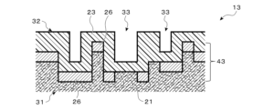
- Fig. 4 is a schematic cross-sectional view showing an outline of a configuration example near the surface of the heater wire holding substrate 13 according to this embodiment.
- the heater wire holding substrate 13 of this embodiment also has a structure in which a heat-sealable resin layer 32 is provided on a nonwoven fabric layer 31.
- the nonwoven fabric structure constituting the nonwoven fabric layer 31 is a structure in which aluminum particles 26 are attached to the surface of the nonwoven fabric 21.
- the heat-sealable resin structure constituting the heat-sealable resin layer 32 is a structure in which particles of a high thermal conductivity material are dispersed in a heat-sealable resin.
- the fine particles of the high thermal conductivity material may be, for example, fine metal particles of aluminum, copper, etc.
- the fine particles of the high thermal conductivity material may be, for example, fine ceramic particles of alumina, magnesia, etc.
- the fine particles of the high thermal conductivity material may be, for example, fine graphite particles.
- the fine particles of the high thermal conductivity material may be, for example, fine silicon carbide particles. That is, for example, the heat-sealable resin structure constituting the heat-sealable resin layer 32 may be a heat-sealable resin having at least one fine particle of aluminum, copper, alumina, magnesia, graphite, etc. dispersed therein.
- the heat-sealable resin layer 32 is formed by the heat-sealable resin material 23 containing a heat-sealable resin structure in which fine particles of a high thermal conductivity material are dispersed.
- the heat-sealable resin material 23 in this embodiment in which fine particles of a high thermal conductivity material are dispersed has superior thermal conductivity compared to the heat-sealable resin material 22 in the second embodiment which is made only of heat-sealable resin.
- the heat-sealable resin layer 32 of the heater wire holding substrate 13 of this embodiment which is formed by the heat-sealable resin material 23 in which fine particles of a high thermal conductivity material are dispersed, easily diffuses heat from the cord-shaped heating element 5 in the planar direction.
- Metal particles such as aluminum and copper have high thermal conductivity. On the other hand, adding a little too much of these hardens the heat-sealable resin material 23, and cracks are likely to occur in the heat-sealable resin layer 32 during debossing. For this reason, metal particles such as aluminum and copper cannot be added in large quantities, and it is not easy to significantly increase the thermal conductivity of the heat-sealable resin layer 32 with these particles. Also, ceramic particles such as alumina and magnesia can be added in slightly larger quantities than the above metal particles. On the other hand, these particles have a relatively low thermal conductivity, and it is not easy to significantly increase the thermal conductivity of the heat-sealable resin layer 32 with these particles.
- Graphite such as scaly graphite has a relatively high thermal conductivity, second only to metal materials. Furthermore, graphite has high lubricity. For this reason, even if a large amount of graphite is added, the heat-sealable resin material 23 does not become very hard. For these reasons, graphite is particularly suitable as a material to be added to the heat-sealable resin material 23.
- Increasing the thermal conductivity of the heat-sealable resin layer 32 in the planar direction using fine particles of a high thermal conductivity material can help with uneven thermal conduction of the aluminum fine particles 26 attached to the nonwoven fabric 21.
- forming a heat-sealable resin layer 32 to which fine particles of a high thermal conductivity material have been added can also eliminate the need for the aluminum fine particles 26 to adhere to the nonwoven fabric 21.
- the heat-sealable resin layer 32 can provide the sheet heater 1 with a far-infrared radiation function in addition to the above-mentioned advantages.
- This far-infrared radiation function allows the seat heater, for example, to heat the human body with heat rays called far-infrared rays in addition to heating the human body through contact thermal conduction.
- a heater wire holding substrate 13 in which graphite has been added to the heat-sealable resin layer 32 an energy-saving effect can be obtained in that the sensible temperature can be maintained even if the power applied to the seat heater is reduced.
- the heat fusion can be performed with debossing using a hot press or the like equipped with an upper die having multiple protrusions.
- the mixed fixing layer 43 formed by the recess 33 is a mixture of the nonwoven fabric layer 31 containing the nonwoven fabric 21 and aluminum particles 26, and the heat fusion resin layer 32 formed of a heat fusion resin structure in which particles of a high thermal conductivity material are dispersed in the heat fusion resin. That is, in the mixed fixing layer 43, the nonwoven fabric 21, aluminum particles 26, particles of a high thermal conductivity material, and heat fusion resin material are mixed.
- the recesses 33 are formed by debossing. This allows the recesses 33 to mitigate the contraction force of the heat-fusible resin material 23 that occurs when the nonwoven fabric material and the heat-fusible resin material 23 are heat-fused together. As a result, the number of pinholes and wrinkles that may occur in the heat-fusible resin layer 32 due to thermal shrinkage is reduced. Furthermore, the heater wire holding substrate 13 as a whole is less likely to be distorted, and a heater wire holding substrate 13 with high flatness is realized. Furthermore, a heater wire holding substrate 13 that is free from the risk of localized heating, such as uneven heating, is realized.
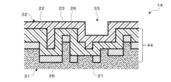
- FIG. 5 is a schematic cross-sectional view showing an outline of a configuration example near the surface of a heater wire holding substrate 14 according to this embodiment.
- the heater wire holding substrate 14 of this embodiment also has a structure in which a heat-sealable resin layer 32 is provided on a nonwoven fabric layer 31.
- the nonwoven fabric structure constituting the nonwoven fabric layer 31 is a structure in which aluminum particles 26 are attached to the surface of the nonwoven fabric 21.
- the heat-sealable resin layer 32 is a structure in which a heat-sealable resin material 23 formed of a heat-sealable resin structure in which particles of a high thermal conductivity material are dispersed in a heat-sealable resin, and a heat-sealable resin material 22 formed of a heat-sealable resin are laminated.
- the heat-sealable resin material 23 formed of a heat-sealable resin structure in which particles of a high thermal conductivity material are dispersed in a heat-sealable resin is similar to the heat-sealable resin material 23 constituting the heat-sealable resin layer 32 of the third embodiment.
- the heat-sealing resin material 22 formed from heat-sealing resin is similar to the heat-sealing resin material 22 that constitutes the heat-sealing resin layer 32 in the second embodiment.
- the heater wire holding substrate 14 is formed by heat fusing a nonwoven fabric material with a heat-fusible resin material 22 formed from a heat-fusible resin, and then heat fusing a heat-fusible resin material 23 formed from a heat-fusible resin structure in which fine particles of a high thermal conductivity material are dispersed in the heat-fusible resin.
- the pinhole can be repaired by further heat fusing the heat-fusible resin material 23 formed from a heat-fusible resin structure in which fine particles of a high thermal conductivity material are dispersed in the heat-fusible resin.
- the heat fusion may be performed with debossing using a hot press or the like equipped with an upper die having multiple protrusions.
- hot pressing or the like with debossing may be performed both in the heat fusion of the heat fusion resin material 22 formed from a heat fusion resin and in the heat fusion of the heat fusion resin material 23 formed from a heat fusion resin structure in which fine particles of a high thermal conductivity material are dispersed in the heat fusion resin.
- hot pressing or the like with debossing may be performed
- hot pressing or the like without debossing may be performed
- hot pressing or the like without debossing may be performed.
- the mixed adhesion layer 44 formed by the recess 33 is a mixture of a nonwoven fabric layer 31 containing nonwoven fabric 21 and aluminum particles 26, and a heat-sealable resin layer 32 formed of a heat-sealable resin structure in which heat-sealable resin 22 and fine particles of a high thermal conductivity material are dispersed in the heat-sealable resin.
- the mixed adhesion layer 43 is a mixture of nonwoven fabric 21, aluminum particles 26, fine particles of a high thermal conductivity material, and heat-sealable resin.
- the vertical positional relationship between the heat-sealing resin material 22 formed from heat-sealing resin and the heat-sealing resin material 23 formed from a heat-sealing resin structure in which fine particles of a high thermal conductivity material are dispersed in the heat-sealing resin may be changed as appropriate.
- the thermal conductivity in the planar direction differs depending on whether only nonwoven fabric 21 is used as the nonwoven fabric material or whether nonwoven fabric 21 with aluminum fine particles 26 attached is used.
- the vertical positional relationship between the heat-sealing resin material 22 formed from heat-sealing resin and the heat-sealing resin material 23 formed from a heat-sealing resin structure in which fine particles of a high thermal conductivity material are dispersed in the heat-sealing resin may be changed depending on the structure.
- the configuration of the planar heater 1 is not limited to a configuration in which the cord-shaped heating element 5 is disposed on a heat-fusible resin layer 32 in which a heat-fusible resin material 22 formed from a heat-fusible resin and a heat-fusible resin material 23 formed from a heat-fusible resin structure in which fine particles of a high thermal conductivity material are dispersed in the heat-fusible resin are laminated.
- the cord-shaped heating element 5 may be disposed between the heat-fusible resin material 22 formed from a heat-fusible resin and the heat-fusible resin material 23 formed from a heat-fusible resin structure in which fine particles of a high thermal conductivity material are dispersed in the heat-fusible resin.
- Fixation of the cord-shaped heating element 5 is not limited to sewing, and may be performed, for example, by heat fusion.
- the cord-shaped heating element 5 is placed between the heat-sealing resin material 22 formed from heat-sealing resin and the heat-sealing resin material 23 formed from a heat-sealing resin structure in which fine particles of a high thermal conductivity material are dispersed in the heat-sealing resin, high thermal conductivity in the planar direction is obtained, and the energy-saving performance of the planar heater 1 in particular is improved.
- Laminating the heat-sealable resin material 22 made of heat-sealable resin and the heat-sealable resin material 23 made of a heat-sealable resin structure in which fine particles of a high thermal conductivity material are dispersed in the heat-sealable resin may increase costs.
- Fig. 6 is a schematic cross-sectional view showing an outline of a configuration example near the surface of a heater wire holding substrate 15 according to this embodiment.
- the heater wire holding substrate 15 of this embodiment also has a structure in which a heat-sealable resin layer 32 is provided on a nonwoven fabric layer 31.
- a heat-sealable resin material that has been heat-treated in advance to shrink and have wrinkles is used as the heat-sealable resin material 24 that forms the heat-sealable resin layer 32.
- the heat-sealable resin material 24 is formed into a film shape at a high temperature of, for example, 220°C using a biaxial stretching device, and is heated to a lower temperature, for example, 180°C using a hot roller or hot air oven, and is wound up in a slow-cooling environment without applying much tension, causing it to shrink appropriately.
- the heat fusion can also be performed with debossing using a hot press or the like equipped with an upper die with multiple protrusions.
- the mixed fixing layer 45 formed by the recesses 33 is a mixture of the nonwoven fabric layer 31 and the heat-sealable resin layer 32, and is a mixture of the nonwoven fabric 21 and the heat-sealable resin material 24.
- the heat-sealable resin material 24 has been shrunk in advance, so that the occurrence of pinholes and wrinkles during heat fusion to the nonwoven fabric 21 can be suppressed, and distortion of the entire heater wire holding substrate 15 can be suppressed.
- ease of processing and high cost-effectiveness can be achieved.
- the pre-shrinking of the heat-sealable resin material may be used not only in combination with the first embodiment as in this embodiment, but also in combination with the second to fourth embodiments.
- [Method of manufacturing heater wire holding substrate] 7 shows an outline of an example of a method for manufacturing the heater wire holding substrate 10.
- a nonwoven fabric material is prepared (step S1), and a fusible resin material is also prepared (step S2).
- the fusible resin material is placed on the nonwoven fabric material, and a pressure heat fusion process accompanied by debossing is performed (step S3), thereby completing the heater wire holding substrate 10.
- Nonwoven fabric was one that met the flame retardant standard FMVSS302, had a basis weight of about 150 g/m 2 , a thickness of 1.5 mm, and a tensile strength of 80 N or more in both the longitudinal and transverse directions.
- the nonwoven fabric material was prepared as follows. That is, the aluminum particles were attached to the nonwoven fabric by vacuum deposition. The degree of vacuum in the vacuum deposition was about 10-6 Torr. The thickness of the aluminum layer on the surface of the nonwoven fabric was about 10 ⁇ m, and the thickness of the aluminum layer became about zero at about 50 ⁇ m in the depth direction of the nonwoven fabric.
- Heat-adhesive resin material As the heat-sealable resin, a commercially available flame-retardant polyolefin resin compound QU1548A1 (manufactured by Mitsubishi Chemical Corporation) was used. Using this resin, a heat-sealable resin material having a thickness of 0.1 mm was produced using a biaxially stretched film manufacturing device consisting of a single-screw extruder.
- the heat-sealable resin material in which fine particles of a high thermal conductivity material are dispersed was prepared as follows. That is, scaly graphite (graphite) MCP-10 (manufactured by Nippon Graphite Industries Co., Ltd.) was used as the fine particles of the high thermal conductivity material. 10 parts by weight of scaly graphite was added to 100 parts by weight of the above-mentioned flame-retardant polyolefin resin compound. The mixture was thoroughly stirred with a kneader.
- a biaxially stretched film manufacturing device having a short-axis extruder was used to prepare a heat-sealable resin material having a thickness of 0.1 mm in which fine particles of a high thermal conductivity material are dispersed, that is, a black heat-sealable resin material having high thermal conductivity.
- the average surface resistance of this black heat-sealable resin material having high thermal conductivity was approximately 10 8 ⁇ /cm 2 .
- the nonwoven fabric material and the heat-fusible resin material were thermally fused using a hot press equipped with an upper die having multiple protrusions.
- the protrusions were truncated cone-shaped protrusions with a diameter of 5 mm at the lower base, a diameter of 3 mm at the upper base, and a height of 50 ⁇ m.
- the density of the protrusions was one protrusion per 3 cm square.
- Example 1 As Example 1, the heater wire holding substrate 11 according to the first embodiment described with reference to Fig. 2 was produced. A heat-fusible resin material 22 not containing dispersed fine particles of a high thermal conductivity material was placed on a nonwoven fabric 21 on which fine aluminum particles were not vacuum-deposited, and these were heat-fused together by a hot press equipped with an upper die having multiple protrusions. The heating temperature by the hot press was 180°C, and the heating time was 10 seconds. This heat fusion formed a mixed fixed layer 41 in which the nonwoven fabric 21 and the heat-fusible resin material 22 were mixed together.
- Example 2 As Example 2, the heater wire holding substrate 12 according to the second embodiment described with reference to Fig. 3 was produced.
- a heat-fusible resin material 22 not containing dispersed fine particles of a high thermal conductivity material was placed on a nonwoven fabric material having aluminum fine particles 26 vacuum-deposited on a nonwoven fabric 21, and these were heat-fused together by a hot press equipped with an upper die having a plurality of protrusions.
- the heating temperature by the hot press was 180°C, and the heating time was 10 seconds.
- This heat fusion formed a mixed fixed layer 42 in which the nonwoven fabric 21, the aluminum fine particles 26, and the heat-fusible resin material 22 were mixed together.
- Example 3 As Example 3, the heater wire holding substrate 13 according to the third embodiment described with reference to FIG. 4 was produced.
- a heat-fusible resin material 23 having fine particles of a high thermal conductivity material dispersed therein was placed on a nonwoven fabric material having aluminum fine particles 26 vacuum-deposited on a nonwoven fabric 21, and these were heat-fused together by a hot press equipped with an upper die having a plurality of protrusions.
- the heating temperature by the hot press was 180° C., and the heating time was 20 seconds.
- This heat fusion formed a mixed fixed layer 43 in which the nonwoven fabric 21, the aluminum fine particles 26, and the heat-fusible resin material 23 having fine particles of a high thermal conductivity material dispersed therein were mixed together.
- Example 4 As Example 4, the heater wire holding substrate 14 according to the fourth embodiment described with reference to FIG. 5 was produced.
- a heat-sealable resin material 22 in which fine particles of a high thermal conductivity material are not dispersed was placed on a nonwoven fabric material in which fine aluminum particles 26 were vacuum-deposited on a nonwoven fabric 21, and these were heat-sealed by a hot press equipped with an upper die having a plurality of protrusions.
- the heating temperature by the hot press was 180° C., and the heating time was 10 seconds.
- a heat-sealable resin material 23 in which fine particles of a high thermal conductivity material are dispersed was placed on top of this, and these were heat-sealed by a hot press equipped with an upper die having a plurality of protrusions.
- the heating temperature by the hot press was 180° C., and the heating time was 20 seconds.
- a mixed fixed layer 44 was formed in which the nonwoven fabric 21, the fine aluminum particles 26, the heat-sealable resin material 22 in which fine particles of a high thermal conductivity material are not dispersed, and the heat-sealable resin material 23 in which fine particles of a high thermal conductivity material are dispersed were mixed.
- Example 5 As Example 5, the heater wire holding substrate 15 according to the fifth embodiment described with reference to Fig. 6 was produced.
- the heating temperature by the hot press was 180°C, and the heating time was 10 seconds. In this way, the heat-fusible resin material 24 in a state in which it had shrunk and small wrinkles were scattered was prepared.
- the heat-sealable resin material 24 which had small wrinkles scattered thereon due to the shrinkage described above, was placed on top of the nonwoven fabric 21 on which the fine aluminum particles had not been vacuum-deposited, and the two were heat-sealed using a hot press equipped with an upper die with multiple protrusions.
- the heating temperature for the hot press was 180°C, and the heating time was 10 seconds.
- This heat sealing formed a mixed adhesive layer 45 in which the nonwoven fabric 21 and the heat-sealable resin material 24 were mixed.
- Comparative Example 1 As Comparative Example 1, a sample was produced by placing a heat-fusible resin material 22 without dispersed fine particles of a high thermal conductivity material on a nonwoven fabric material in which aluminum fine particles 26 were vacuum-deposited on a nonwoven fabric 21, and heat-fusing them together using a hot press equipped with a flat upper die without protrusions. The heating temperature in the hot press was 180° C., and the heating time was 10 seconds. That is, a heater wire holding substrate having the same layer structure as in Example 2 but without a recess 33 was produced.
- Comparative Example 2 As a comparative example 2, a sample consisting of only the nonwoven fabric 21 on which no fine aluminum particles were vacuum-deposited was prepared as the heater wire holding substrate.
- a sheet heater was produced using the heater wire holding substrates according to the above-mentioned respective Examples and Comparative Examples. That is, as shown in FIG. 1 , a sheet heater 1 was produced in which a cord-shaped heating element 5 was fixed onto each heater wire holding substrate 10.
- the cord-like heating element 5 was as follows.
- the core was made of fully aromatic polyester fibers bundled together and had an outer diameter of 0.25 mm.
- the resistance wire was made of a copper-tin 3% alloy wire having a diameter of 0.075 mm. Three resistance wires were twisted together to make a twisted wire, and six of the twisted wires were aligned and wound transversely around the winding core at a pitch of 1.815 mm.
- An insulating coating layer of ETFE resin was extrusion-coated thereon to a thickness of 0.2 mm to produce a cord-like heating element 5 having an outer diameter of 0.9 mm.
- a cord-shaped heating element 5 was sewn and fixed to the surface of the heater wire holding substrate 12 of Example 2, and a heat-sealable resin material 23 in which fine particles of a high thermal conductivity material were dispersed was placed on top of that, and the planar heater 1 was fabricated by heat-sealing them using a hot press equipped with an upper mold without protrusions.
- the planar heater 1 used in the following experiments was
- thermocouples were used for the measurements.
- the thermocouples were placed in positions that did not contact the cord-shaped heating element, at the centre of the sheet heater and about 5 cm to the left and right.
- the tip of each thermocouple was fixed to the sheet heater with adhesive.
- the three thermocouples were connected to a general-purpose temperature logger and the temperature change every second was recorded, with the average of the three values being taken as the measured value.
- the seat heater was measured in this way under environmental conditions close to standalone conditions in order to clarify the essential performance differences between each sample.
- a temperature control thermocouple was also attached to the center of the sheet heater, adjacent to the measurement thermocouple.
- the temperature control thermocouple was positioned so that it did not come into contact with the cord-shaped heating element.
- the temperature control thermocouple was connected to a temperature controller. Since the resistance of the cord-shaped heating element is temperature dependent, the applied voltage (approximately 12.5 V) was fine-tuned for each sample while checking the power meter in advance so that the power consumption at 40°C was 82.1 W.
- the sheet heater was connected directly to a DC power supply without going through a temperature controller.
- the temperature measured using three thermocouples rose.
- the measurement value was the average of the three temperatures recorded by the temperature logger.
- the rise time was measured as the time from when the power supply was switched on until the surface temperature of the sheet heater reached 40°C.
- the surface heater was connected to a DC power source via an ON-OFF type temperature controller.
- the temperature controller was set to an OFF point temperature of 40°C, an ON point temperature of 39.5°C, and a hysteresis width of 0.5°C.
- the switch was turned ON to enter automatic temperature control mode, and power consumption was measured using an integrated wattmeter. The average integrated power consumption over a 30-minute period from the moment the power switch was turned ON was determined as the average power consumption.
- the sheet heater was hung in the air at 25°C in a windless environment and connected to a DC power source via a temperature controller.
- the temperature controller was set to 40°C and put into automatic temperature control mode.
- a black cloth large enough to hide the sheet heater was stretched in the air 15 cm away from the surface of the seat heater.
- the surface temperature of the black cloth, which corresponds to the center of the sheet heater was measured using a far-infrared thermograph. Measurements were taken at 1-minute intervals for 10 minutes, and the average temperature was determined as the far-infrared heating.
- a sheet heater was sandwiched between an insulating elastic sheet for automobiles and a skin cover.
- a DC power source was connected to the sheet heater, and 13.5 V DC was applied.
- Sitting stress was simulated using an anthropomorphic robot.
- One cycle consisted of rotating and sliding the seat to get in and sit on it, applying a load of 40 kg, and vibrating up and down 20 times, followed by the reverse motion to get out and get off. This cycle was repeated 10,000 times in a test.
- a sheet heater was sandwiched between an insulating elastic sheet for automobiles and a skin cover.
- a direct current power source was connected to the sheet heater, and the switch was turned off to de-energize the surface of the skin cover.
- the electrostatic charge was immediately measured at a distance of 25 mm using a static electricity tester.
- the heater wire holding substrates according to Examples 1 to 5 which were manufactured using a hot press equipped with an upper die having a protrusion 50 ⁇ m in height, had recesses 33 formed with a depth roughly corresponding to the protrusion of the upper die.
- the nonwoven fabric layer 31 sank 10 ⁇ m or more into the recesses 33.
- the heat-sealable resin layer 32 was sufficiently embedded in the nonwoven fabric layer 31 in the depth direction, and that a mixed fixed layer was formed that contained a mixture of nonwoven fabric, aluminum particles, high thermal conductivity material particles, heat-sealable resin material, etc.
- the distortion dimensions of the heater wire holding substrate were as follows. The distortion of the heater wire holding substrate was most pronounced at the four corners.
- the heater wire holding substrates of Examples 1 to 5, which had recesses 33 had small distortion. The distortion was so great that it was possible to sew the cord-shaped heating element 5 with an automatic sewing machine.
- the temperature was measured using a black cloth placed 15 cm away from the sheet heater.
- the sheet heater is used as a seat heater, the seat heater and the human body are in close contact.
- the sensation of warmth felt by the human body due to far infrared rays is greater than in this example.
- the heat energy contains fewer heat ray components that are unsuitable for heating the human body, and more far-infrared components that are effective for heating the human body. It has become clear that seat heaters using these materials can achieve energy-saving effects through far-infrared radiation.
- the heat-sealable resin layer 32 having the recesses 33 has sufficient durability against seating stress. It was also confirmed that the heat-sealable resin layer 32 having the recesses 33 can adequately protect the aluminum particles 26 adhering to the nonwoven fabric 21, providing a high level of safety.
- the heat-sealing resin material 23 in which the particles of a high thermal conductivity material are dispersed functions as an antistatic body. It was revealed that the seat heater using the heat-sealing resin material 23 in which the particles of a high thermal conductivity material are dispersed can reduce various noises caused by static electricity compared to the seat heater using the heat-sealing resin material 22 in which the particles of a high thermal conductivity material are not dispersed.
- a seat heater using the heater wire holding substrate 10 according to the embodiment can use a cord-shaped heating element, which has a proven reliability. Furthermore, a seat heater using the heater wire holding substrate 10 according to the embodiment can achieve a fast heating rate, low power consumption, and energy savings, even if the heater wire holding substrate is made of a thin nonwoven fabric with a low basis weight.
- the seat heater using the heater wire holding substrate 10 according to the embodiment is resistant to seating stress, has a high degree of freedom in design, and is also excellent in cost performance. Furthermore, the seat heater using the heater wire holding substrate 10 containing the heat-fusible resin material 23 in which fine particles of a highly thermally conductive material are dispersed has a function suitable for heating the human body by far-infrared radiation, and also has an antistatic function.
Landscapes
- Engineering & Computer Science (AREA)
- Mechanical Engineering (AREA)
- Chemical & Material Sciences (AREA)
- Composite Materials (AREA)
- Textile Engineering (AREA)
- Surface Heating Bodies (AREA)
Priority Applications (4)
| Application Number | Priority Date | Filing Date | Title |
|---|---|---|---|
| JP2023557671A JP7475756B1 (ja) | 2023-06-09 | 2023-06-09 | ヒータ線保持基材 |
| PCT/JP2023/021588 WO2024252678A1 (ja) | 2023-06-09 | 2023-06-09 | ヒータ線保持基材 |
| CN202380090963.2A CN120500905A (zh) | 2023-06-09 | 2023-06-09 | 加热丝保持基材 |
| KR1020257018559A KR102894350B1 (ko) | 2023-06-09 | 2023-06-09 | 히터선 보호지지 기재 |
Applications Claiming Priority (1)
| Application Number | Priority Date | Filing Date | Title |
|---|---|---|---|
| PCT/JP2023/021588 WO2024252678A1 (ja) | 2023-06-09 | 2023-06-09 | ヒータ線保持基材 |
Publications (1)
| Publication Number | Publication Date |
|---|---|
| WO2024252678A1 true WO2024252678A1 (ja) | 2024-12-12 |
Family
ID=90827073
Family Applications (1)
| Application Number | Title | Priority Date | Filing Date |
|---|---|---|---|
| PCT/JP2023/021588 Ceased WO2024252678A1 (ja) | 2023-06-09 | 2023-06-09 | ヒータ線保持基材 |
Country Status (4)
| Country | Link |
|---|---|
| JP (1) | JP7475756B1 (enExample) |
| KR (1) | KR102894350B1 (enExample) |
| CN (1) | CN120500905A (enExample) |
| WO (1) | WO2024252678A1 (enExample) |
Citations (8)
| Publication number | Priority date | Publication date | Assignee | Title |
|---|---|---|---|---|
| JPH02301405A (ja) * | 1989-05-16 | 1990-12-13 | Kobunshi Giken Kk | コンクリート型枠用板及びその製造方法 |
| JPH06260264A (ja) * | 1993-03-02 | 1994-09-16 | Dainippon Ink & Chem Inc | 面状発熱体の製造方法 |
| JPH11254609A (ja) * | 1998-03-16 | 1999-09-21 | Sekisui Chem Co Ltd | 積層シートの製造方法 |
| JP2003147605A (ja) * | 2001-11-13 | 2003-05-21 | Toray Ind Inc | 衣料製品 |
| JP3119185U (ja) * | 2005-12-02 | 2006-02-16 | 岸本産業株式会社 | 断熱容器 |
| JP2006278202A (ja) * | 2005-03-30 | 2006-10-12 | Matsushita Electric Ind Co Ltd | 高分子発熱体及びその製造方法 |
| JP2009190235A (ja) * | 2008-02-13 | 2009-08-27 | Kao Corp | 複合シートの製造方法 |
| WO2020149306A1 (ja) * | 2019-01-15 | 2020-07-23 | 積水化学工業株式会社 | 面状発熱体 |
Family Cites Families (5)
| Publication number | Priority date | Publication date | Assignee | Title |
|---|---|---|---|---|
| JP4202071B2 (ja) | 2001-09-20 | 2008-12-24 | 株式会社クラベ | シートヒータとシートヒータの製造方法 |
| KR20130002247U (ko) * | 2011-10-04 | 2013-04-12 | 이현숙 | 부분별 온도조절이 가능한 발열매트 |
| CN102555312B (zh) * | 2011-12-29 | 2016-07-13 | 福建恒安集团有限公司 | 一种复合材料及其制备工艺 |
| CN113966273A (zh) * | 2019-06-17 | 2022-01-21 | 东洋纺株式会社 | 成型用片和成型体 |
| CN111546822B (zh) * | 2020-05-12 | 2022-02-01 | 李季 | 一种布贴国画布料、布料处理工艺及布贴画制作方法 |
-
2023
- 2023-06-09 JP JP2023557671A patent/JP7475756B1/ja active Active
- 2023-06-09 WO PCT/JP2023/021588 patent/WO2024252678A1/ja not_active Ceased
- 2023-06-09 KR KR1020257018559A patent/KR102894350B1/ko active Active
- 2023-06-09 CN CN202380090963.2A patent/CN120500905A/zh active Pending
Patent Citations (8)
| Publication number | Priority date | Publication date | Assignee | Title |
|---|---|---|---|---|
| JPH02301405A (ja) * | 1989-05-16 | 1990-12-13 | Kobunshi Giken Kk | コンクリート型枠用板及びその製造方法 |
| JPH06260264A (ja) * | 1993-03-02 | 1994-09-16 | Dainippon Ink & Chem Inc | 面状発熱体の製造方法 |
| JPH11254609A (ja) * | 1998-03-16 | 1999-09-21 | Sekisui Chem Co Ltd | 積層シートの製造方法 |
| JP2003147605A (ja) * | 2001-11-13 | 2003-05-21 | Toray Ind Inc | 衣料製品 |
| JP2006278202A (ja) * | 2005-03-30 | 2006-10-12 | Matsushita Electric Ind Co Ltd | 高分子発熱体及びその製造方法 |
| JP3119185U (ja) * | 2005-12-02 | 2006-02-16 | 岸本産業株式会社 | 断熱容器 |
| JP2009190235A (ja) * | 2008-02-13 | 2009-08-27 | Kao Corp | 複合シートの製造方法 |
| WO2020149306A1 (ja) * | 2019-01-15 | 2020-07-23 | 積水化学工業株式会社 | 面状発熱体 |
Also Published As
| Publication number | Publication date |
|---|---|
| KR102894350B1 (ko) | 2025-12-03 |
| CN120500905A (zh) | 2025-08-15 |
| KR20250103746A (ko) | 2025-07-07 |
| JP7475756B1 (ja) | 2024-04-30 |
| JPWO2024252678A1 (enExample) | 2024-12-12 |
Similar Documents
| Publication | Publication Date | Title |
|---|---|---|
| JP5201137B2 (ja) | 高分子抵抗体 | |
| JP2010169303A (ja) | 電気採暖具 | |
| TW200925344A (en) | Electric heating fabric device | |
| JP2010052710A (ja) | 加熱装置およびそれを用いた車両用暖房装置 | |
| JP2006506784A (ja) | 被覆された導体と導体が形成されるヒータ | |
| KR101748757B1 (ko) | 발열시트 및 그의 제조방법 | |
| US11089658B2 (en) | Heating element | |
| TW201412178A (zh) | 電熱(地)毯之發熱裝置及其製造方法與發熱系統 | |
| JP7475756B1 (ja) | ヒータ線保持基材 | |
| JP2009199794A (ja) | 面状発熱体 | |
| US8592725B1 (en) | Taped sealed heating system for low voltage heated garments | |
| CN115361890A (zh) | 用于热管理的多层缓冲组件 | |
| KR102820569B1 (ko) | 면상 히터 | |
| JP7575223B2 (ja) | 加熱装置及び冷却装置 | |
| TWI461092B (zh) | 面狀加熱器 | |
| TW201134287A (en) | Manufacturing method of flexible flat bar heater by using carbon fiber filament as heating head | |
| JP2015232419A (ja) | 面状採暖具およびその製造方法 | |
| CN118591034A (zh) | 一种碳材料电热膜 | |
| CN220273890U (zh) | 一种使用安全的电热垫产品 | |
| CN101422075A (zh) | 可加热的织物 | |
| JP2002175870A (ja) | 面状ヒータ及びその製造方法 | |
| JP2531356Y2 (ja) | 電気カーペット | |
| JPH02215078A (ja) | 電気毛布本体とその製造方法 | |
| JPS6242463Y2 (enExample) | ||
| JPS631433Y2 (enExample) |
Legal Events
| Date | Code | Title | Description |
|---|---|---|---|
| WWE | Wipo information: entry into national phase |
Ref document number: 2023557671 Country of ref document: JP |
|
| 121 | Ep: the epo has been informed by wipo that ep was designated in this application |
Ref document number: 23940774 Country of ref document: EP Kind code of ref document: A1 |
|
| WWE | Wipo information: entry into national phase |
Ref document number: 1020257018559 Country of ref document: KR |
|
| WWP | Wipo information: published in national office |
Ref document number: 1020257018559 Country of ref document: KR |
|
| WWE | Wipo information: entry into national phase |
Ref document number: 202380090963.2 Country of ref document: CN |
|
| WWP | Wipo information: published in national office |
Ref document number: 202380090963.2 Country of ref document: CN |
|
| NENP | Non-entry into the national phase |
Ref country code: DE |